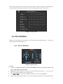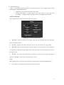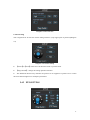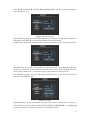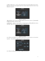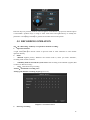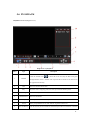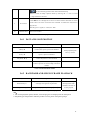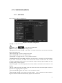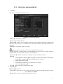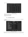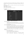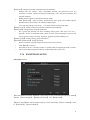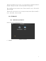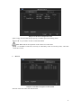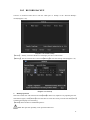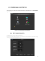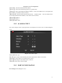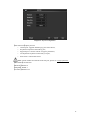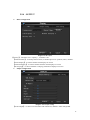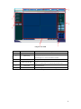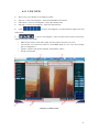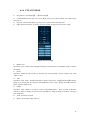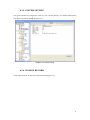
1
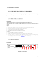
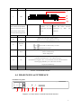
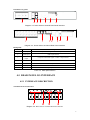
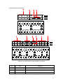
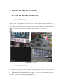
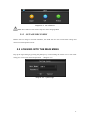
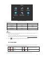
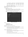
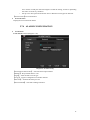
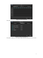
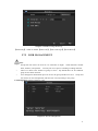
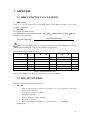
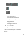
Embedded DVR User Manual Home Series Thank you for purchasing our Embedded DVR. This manual is applicable to Home Series. Please go through this User Manual before operating so as to use the DVR in the correct and safe way. The content of this manual is subject to change without notice. 1 1. PRECAUTIONS Please observe the following precautions, in order to avoid damage or loss of data caused by improper operation. Install DVR within the temperature and humidity requirements. Do not install DVR in humid, dusty or smoky environment. Require a solid mounting surface for installation. Do not block any ventilation openings. Install under the manufacturer's instructions. Do not spill liquid of any kind on device. Do not put any other equipment on device. Do not dismantle the device. Select specified HDD by manufacture. 2. NOTE This user manual is for reference only, subject to available products. This user manual may contain inaccurate data or printing error. Updates to the manual or products themselves will occur without further notification. Contact the customer service department when you are in doubt or documentations. 2 Table of Contents 1. PRECAUTIONS 2 2. NOTE 2 3. PRODUCT INTRODUCTION 5 3.1 SUMMARY 3.2 FEATURES 5 5 4. INSTALLATION 7 4.1 CHECK DVR AND ITS ACCESSORIES 4.2 HDD INSTALLATION 4.3 FRONT PANEL 4.4 REAR PANEL & INTERFACE 4.5 REAR PANEL I/O INTERFACE 4.5.1 INTERFACE DESCRIPTION 4.5.2 ALARM INPUT 4.5.3 ALARM OUTPUT 4.5.4 PTZ 7 7 7 8 9 9 11 11 11 5. LOCAL OPERATION GUIDE 12 5.1 POWER ON /OFF OPERATION 5.1.1 POWER ON 5.1.2 POWER OFF 5.1.3 OUTAGE RECOVERY 5.2 LOGGING INTO THE MAIN MENU 5.3 LIVE VIEW 5.4 PTZ CONTROL 5.4.1 PTZ CONTROL 5.4.2 PTZ SETTING 5.5 RECORDING OPERATION 5.6 PLAYBACK 5.6.1 FAST AND SLOW MOTION 5.6.2 BACKWARD AND SINGLE FRAME PLAYBACK 5.7 CONFIGURATION 5.7.1 SETTING 5.7.2 CHANNEL MANAGEMENT 5.7.3 NETWORK SETTING 5.7.4 ALARM CONFIGURATION 12 12 12 13 13 14 15 15 17 20 22 23 23 24 24 25 26 29 3 5.7.5 USER MANAGEMENT 5.7.6 EXCEPTIONS SETUP 5.8 STORAGE 5.8.1 HDD MANAGEMENT 5.8.2 RECORD BACKUP 5.9 PERIPHERAL EQUIPMENTS 5.9.1 PTZ CONFIGURATION 5.9.2 ALARM OUTPUT 5.9.3 PORT CONFIGURATION 5.9.4 OUTPUT 5.10 MAINTENANCE 5.11 SHUTDOWN 31 32 33 33 35 36 36 37 37 39 40 42 6. ON-LINE OPERATION 43 6.1 WEB OPERATION GUIDE 43 6.1.1 NETWORK CONNECTION 43 6.1.2 CONTROL SETUP & LOGIN / LOG OFF 6.1.3 LIVE VIEW 6.1.4 PTZ CONTROL 6.1.5 SYSTEM SETTING 6.1.6 SEARCH RECORD 6.2 CLIENT OPERATION GUIDE 43 45 46 47 47 48 7. APPENDIX 49 7.1 HDD CAPACITY CALCULATION 7.2 MOUSE CONTROL 7.3 TROUBLESHOOTING 49 49 50 4 3. PRODUCT INTRODUCTION 3.1 SUMMARY Our Embedded Digital Video Recorder is an excellent digital surveillance product which adopts H.264 video compression, hard disk recording, TCP/IP transmission, and a Linux based OS in addition to some of the more advanced technologies in the information technology industry. This enable a more stable, reliable and high picture quality. These products support synchronized video and audio recording, playback, and monitoring. This series also supports network based system control, as well as excellent network streaming capabilities. 3.2 FEATURES Features switched according to the soft/hardware edition. Live surveillance composite video signal (BNC) or VGA output Live video by monitor, TV or display devices Single screen / four-screen / nine-screen / sixteen-screen output Privacy masking, character overlay, unusual states message, Compression Apply H.264 video compression and G.711 audio compression. Recording Motion detection, alarm linkage recording mode, SATA HDD and SMART tech of local HDD. USB backup or network backup. Playback Video searching, playback, and backup via head end or web interface. Multiple playback modes: slow motion, fast forward, frame by frame and skip backward. Network backup or USB 2.0 ports for backup devices. Multi-channel playback synchronization Camera control & Alarm PTZ (using RS-485), camera control, preset, tour, pattern setting and call. Three-dimensional positioning ( in PTZ condition ) Alarm management Multi-channel alarm inputs could be connected with standard devices such as infrared, smoke detection, vibration alarm. Alarm detection for motion, video loss and masking. 5 Multi-channel alarm outputs which link alarm with light control. Interface USB2.0, Ethernet interface, RS485, etc. Network Support TCP/IP and TCP, UDP, RTP transmission. Support online real-time surveillance and record search, playback, manage. Support dynamic IP addressing, PPPOE, DDNS Access DVR by WEB Interface (Internet Explorer) NTP timing, alarm by Email, etc. Operation Support front panel, remote control and mouse control. Simple operation, menu driven with help tips. 6 4. INSTALLATION 4.1 CHECK DVR AND ITS ACCESSORIES Please carefully check the contents following the packing list. If any of the items are missing, please contact with your dealer. 4.2 HDD INSTALLATION Preparation: A Phillips head screwdriver is required to disassemble and reassemble the unit. This series DVR allows a maximum 2 HDDs. HDD capacity is tested up to 2TB at the time of writing Steps: Remove the metal top cover by removing two screws from the sides of the cover. Place the hard disks on a flat table and fasten it by screws. Connect the power and data cables to the HDD. Reinstall the metal top cover and fasten it by screws. Caution: Only use HDDs specified by the manufacturer. HDD will be formatted automatically during startup, it may cause data loss. Recording duration is decided by HDD capability and DVR parameters (recording setup, encoding setup). Please see the form in chapter 7.1(for reference only). 4.3 FRONT PANEL Front panel: Ⅰ Ⅱ Ⅲ Ⅳ Ⅴ Ⅵ Ⅶ Ⅷ Diagram 4-1: Front Panel 7 Index Name Ⅰ LCD Functions 3. HDD status and 4. Cycling display the recording Show external alarm channels; numbers. status Show error and error code: E××; flash label refer HDD (distinguish Show remote control address; error. “MOVE”) 1. IP, time; 2. Connection status “E” and and motion by detection “REC” and Show the internal temperature Ⅱ IR Ⅲ Esc Receive remote control signal Back to previous menu; operation cancel; Back to live view when playing back records Direction control Ⅳ Direction keys & : menu mode, use direction keys to select & : playback speed control Operation confirm; Ⅴ Enter Switch to default button; Menu configuration. Single screen view: PTZ control and image color; Setup motion detection area: “Fn” with direction keys; Ⅵ Fn Clear function: long press “Fn” (≥1.5 seconds) to clear all content in edit box; Switch typing methods by “Fn” when select a textbox; Cooperate with menu tips. Ⅶ USB Connect with mouse , HDD, etc. Ⅷ ON/OFF Power on/off operation Form 4-1: Front Panel Function 4.4 REAR PANEL & INTERFACE 4-channel rear panel Diagram 4-2: Home Series 4-channel Rear Panel Interface 8 8-channel rear panel 1 2 3 4 5 7 6 Diagram 4-3: Home Series 8-channel Rear Panel Interface Diagram 4-4: Home Series 16-channel Rear Panel Interface Back panel: Index Name 1 Video input Composite video signal (CVBS)input interface 2 Audio input Audio input interface 3 Video/Audio output Description Composite video/audio signal(CVBS)output interface 4 NI RJ45 5 VGA VGA output interface 6 Power input DC 12V 7 Ports Alarm input/output, RS-485 interface Form 4-2:Back panel function 4.5 REAR PANEL I/O INTERFACE 4.5.1 INTERFACE DESCRIPTION 4-channel device I/O interface Diagram 4-5: Home Series 4-channel DVR I/O Interface 9 8-channel device I/O interface Diagram 4-6: Home Series 8-channel DVR I/O Interface Diagram 4-7: Home Series 16-channel DVR I/O Interface Index Name Description 1 Alarm input Connection for external Alarm Peripherals (PIR Sensor, Alarm Panel) 2 GND Grounding 3 Alarm output Connection for external devices (Piezo, buzzer, siren) 4 RS485 Communication terminal for Pan/Tilt/Zoom cameras Form 4-3: DVR I/O Description 10 4.5.2 ALARM INPUT Normal open or close form of alarm input type. Com port of alarm detector connected with GND and connect with DVR’s GND. NC port(or NO port)of alarm detector connect with DVR input interface. Alarm detector adopts external power supply and the same ground with DVR. 4.5.3 ALARM OUTPUT Alarm output (relay output); please refer relay parameters bellow in order to avoid device damage. Relay parameters Contact Material Electric property Silver Maximum switching power 240VA,48W Maximum switching voltage 125VAC,60VDC Maximum switch current 2A Form 4-4: Relay Parameters 4.5.4 PTZ A, B ports of RS-485 linked with A, B ports of PTZ decoder. A is the RS-485 + terminal, B is the RS-485 – terminal. Parallel connect 120Ω resistances at A, B ports to reduce signal reflex if there are several PTZ decoders. 11 5. LOCAL OPERATION GUIDE 5.1 POWER ON /OFF OPERATION 5.1.1 POWER ON Connect power supply and press the power botton on the front panel to startup the DVR. The power light is on and “ ” displayed on the LCD during startup. Multiple live view is defaulted when turn on DVR unless it’s in the period which set for recording.(Diagram 5-1) Note:Power supply has to match with DVR, any other substitutes are not allowed. Diagram 5-1:live view 5.1.2 POWER OFF Hold down on-off key to turn off device(only operated by the user who has power off authority). 【Main Menu】→【Power off】→【Power off】 (tip: This is the recommended method to shut down, in order to avoid damaging the HDD/system). 12 Diagram 5-2:turn off device Note: turn off device and switch off power when changing HDD 5.1.3 OUTAGE RECOVERY Reboot after an outage or forceful shutdown, the DVR will save the record before outage and return to normal operation mode. 5.2 LOGGING INTO THE MAIN MENU Pop up the login dialog by pressing the [Enter] key or left clicking the mouse in live view mode and type in correct username and password. (Diagram 5-3) Diagram 5-3:system login 13 Diagram 5-4:System Menu Default users: User Type Name Default Password Administrator admin 123456 User user 123456 Hidden default default Form 5-1:default users Note: Password security: occur alarm after three times wrong input and system lockout in 30 minutes after 5 unsuccessful login. For security consideration, please modify the default password. For information on how to add groups, users and modify users information, please refer chapter 5.7.5 Uses Management Click to toggle the character input method in mouse mode. 5.3 LIVE VIEW Power on the DVR and entry the default live view mode. There are date, time, channel names and icons which indicate status display on screen. The icons represent: 1 2 Shows on scream when in recording Shows on scream when motion detection 3 4 Shows on scream when video loss Shows on scream when the channel is locked Switch display screens by either the front panel, remote control or mouse control. 14 If you have enable the screen message for external alarm, video loss, masking, motion detection, network and IP conflict alarm, the below interface would popup when those alarm occur. Diagram 5-5:alarm status 5.4 PTZ CONTROL Right click on the selected screen under live view mode and choose Pan/Tilt/Zoom. You will see the following interface(Diagram 5-6). 5.4.1 PTZ CONTROL Diagram 5-6:PTZ control General Control PTZ direction, step size, zoom, focus, IRIS, presets, tour, pattern, border scan, AUX switch, light switch, auto pan. Step size controls PTZ speed, e.g. step size 8 is moved faster than step size 1. (you can set 1-8 step size by soft keyboard or keys on front panel) Click and of zoom, focus and IRIS to modify zoom, focus and brightness. Support PTZ eight-direction rotation.(If you are using the front panel, it is only four-direction). 15 Quick positioning: 〈SIT〉: in the middle of direction keys is the quick position key. It only support mouse control and support by certain PTZ protocols. Single click to move this point to the screen center. Clicking and draging a specific region causes the camera to center and zoom accordingly. Dragging from left to right zooms in, and right to left zooms out. Advanced Functions Click “Page Switch” to enter the advanced function interface. Diagram 5-7:PTZ control-advanced 【Preset】: input the wanted preset number which has been recorded. Then click the preset button to call the function. 【Tour】: input the tour number and click “tour” to run it or stop tour by “stop” button. 【Patrol】: input the patrol number and click “patrol” to on the function. The camera will work under the created patrol path. Right click to hide the menu. Click the direction key in menu to stuo the patrol. 【Line】: click “line” and call the line scan function. As the line scan is applied the button will turn to【Stop】, if you want to stop the motion, click it. AUX Click “Page Switch” to enter the AUX interface. (corresponding with protocal)(Diagram 5-8) Aux number is accorded with the auxiliary switch on decoder. 16 Diagram 5-8:Aux function Camera Setting Click “Page Switch” to enter the camera setting interface. (only support part of protocal)(Diagram 5-9) Diagram 5-9:camera setting 【Enter】or【Exit】refers access to the menu items or quit the menu. 【Page Switch】: change the setting operation interface. The shadowed direction key indicates the protocal is not supported. Up/down use to switch the items and left/right use to modify the parameters. 5.4.2 PTZ SETTING 17 Click 【Set】to set【Preset】,【Tour】,【Pattern】,【Border】. Gray keys represent unsupported function(Diagram 5-10). Diagram 5-10:preset setting 【Preset】setting: Diagram 5-10click【Preset】and input a number to assign these coordinates as that number. Click【Save】to save these coordinates to that preset number Call【Preset】: input preset number and click “preset” on left side to call a specific preset location. 【Tour】setting: Select “Tour”; input numbers in “Path” and “preset”. Click【Add Preset】to add one preset in cruise path, repeat to add more than one presets. Click 【Clear Preset】to delete a preset, repeat to delete more.(Note: This feature is only available in certain protocols) Call【Tour】: Diagram 5-11input a path number and click “Tour” on the left side to start this function. Click【Stop】to quit.. Diagram 5-11:tour 【Pattern】setting: Assign a path number, and click start to begin recording. Once recording, go back to the PTZ controls in order to modify your【zoom】,【focus】and【IRIS】, etc. Click【Stop】 in “Pattern” settings once finished, in order to save that pattern number 18 Call【Pattern】:Diagram 5-12 input a pattern path number and click 【Pattern】to call the function. Right click to hide the menu in pattern mode; You can take manual control of the camera to stop the pattern at any time. Diagram 5-12:pattern 【Border】setting: move camera to left/right boundary by direction key and click 【Left Border】 and【Right Border】to confirm the setting. Call【Border】: Diagram 5-13click “Border” to start the function, the【Border】button will turn to【Stop】. Right click to hide menu and single click【Stop】to quit. Diagram 5-13:border Click 【Page Switch】again to set additional PTZ functions. These functions are also protocol dependent.(only DH-SD1 and DH-SD2 realize the function presently) Click 【Page Switch】again to set camera(support a few protocol) 19 Direction keys are primarily used for menu navigation. If the button is greyed out, then the option is unavailable. Up/down keys is using to select menu items and right/left keys to modify the parameters. Click【Page Switch】to go back the window shown in the picture. 5.5 RECORDING OPERATION Tip:the “Recording” authority is required for manual recording. Operation interface A right click【REC】on remote control in preview mode or click “Manual” to enter manual operation directly. Status Manual: highest priority. Whatever the current mode is, when you select “Manual”, recording mode switch to normal. Schedule:If this is selected, the system will record according to the schedule (regular, MD or alarm) in “Record Config”. Stop:all channels stop recording All start:all channels recording start All stop:all channels recording stop(Diagram 5-14) Diagram 5-14:manual record Start/stop recording 20 Please confirm the recording mode before change the channel status. Here you can check whether the status is on or off(blank refers the recording off; ticked is the recording on). To change the status, select a channel by using the 【】/【】key and then change the recording mode by using the【】/【】or numeric key. 21 5.6 PLAYBACK Playback interface(Diagram 5-15): Diagram 5-15:playback Index Type Description Click the calendar icon-1 Calendar to show the record list (only the dates with green background take records.)and then click a specific date to call the record. The list will be upgraded automatically. 2 Time Select record start and end time. 3 Play Playback control: stop/play, pause, fast, slow, previous/next frame in pause. 4 Record Type 5 Channel Select 6 Play Turn to previous/next record and previous/next channel. 7 Search Once your parameters are set, click “Search” to get the results in list 8 Record Backup Search record by external alarm, MD and all alarm record Select record channel Tick the records you want(enable to select backup records in two channels) and click 22 to call out backup operation menu and confirm the backup. Remove records in backup operation menu by removing the “” next to records (single channel list 32 items) Search results show in the results list. Click / to move through the records in list which contains maximum 128 search 9 results. Select one of the records and click “ENTER” or double-click left mouse to Record List play the file. Record type: R—regular; A—alarm; M—MD. 10 Window Select Select focus window Form 5-2:playback 5.6.1 FAST AND SLOW MOTION Keys Description Playback fast motion: For changing between fast motion in slow and The key: normal mode, speed 1, speed 2 are alterable. Playback slow motion: Switch to slow motion in fast and normal mode, the key: ► speed 1, speed 2 are alterable. Play/Pause: ►/ Control Play/Pause in slow/fast mode Previous/Next Valid in playback mode, click│ and │ to RMKS Actual playback speed varies by versions switch to previous or next recording in the same channel Form 5-3:fast and slow motion 5.6.2 BACKWARD AND SINGLE FRAME PLAYBACK Keys Description RMKS Backward: Single left click backward key to play backwards In backward and single Backward key and single click again to stop back run frame playback mode, Manual single frame playback single frame playback by clicking │ and │ click ►/ to return to normal playback Form 5-4:backward and single frame playback Tip: 1. The current playback speed, channel, time and progress are displayed on the front panel. 2. Playback type and speed are related to product version, please refer panel prompt. 23 5.7 CONFIGURATION 5.7.1 SETTING Enter “Setting” under “Configuration”: Diagram 5-16:system configuration 【Time】:set the current time Note:click to save the time modification. 【Date Format】:to modify the date display format 【Daylight Saving Time (DST)】:click “DST” to enable the function, and enter the local DST starting and ending time. 【Date Separator】:to select the separator for date 【Time Standard】:24 hr or 12 hr display mode 【Language】 :language selection(vary by different model)。 【Full HDD Solution】:when HDD is Full, there are two options: “Overwrite” or “Stop recording”. If you select “Overwrite”, the DVR will overwrite the earliest recorded files and continue recording as all HDD in DVR are full. If you select the “Stop recording” option the DVR will stop recording when it reaches capacity. 【Video Length】:to set time length for each record, default is 60 minutes, the maximum is 120 minutes. 【No.】:number more than one DVR, click “Ad” button on remote control and input a number to select the corresponding DVR to operate. 【Video Standard】standard: PAL/NTSC(alter for different model). 【Menu Standby Time】:This ranges from 0-60 minutes. This is the amount of time without a keypress before the DVR will automatically logout of the current user. 24 5.7.2 CHANNEL MANAGEMENT Standard The “Base Config” interface(Diagram 5-17): Diagram 5-17:record configuration 【Channel】:the channel selection 【Video Compression】:H.264 【Resolution】 :options are D1/CIF/QCIF, frame rate scope is different depending on channel and resolution. Extra stream of 1~16 channel is forced to QCIF while the main stream parameters are selectable. 【FPS】PAL: 1fps-25fps; NTSC: 1fps-30fps Note:resolution and frame rate are vary depending on DVR model. 【Stream Control】 :Constant Bitrate or Variable Bitrate. There are 6 levels of image quality in Variable Bitrate, 6 is the best but it is fixed in Constant Bitrate 【Audio/Video】:Enable or disable the recording of video and audio per channel. 【More】: Modify【Channel Name】,【Date Display】,【Channel Title】,【Time Title】setting Modify【View Tampering】setting, tampering area is alterable. Modify【Snapshot】setting. Modify【Prerecord】setting, the maximum is 30 seconds. Turn on/off【Redundancy】 【Copy】:copy one channel’s configuration to other Record plan Record Config interface: 【Channel】:to select channel. Green, yellow and red refer to the normal, MD and alarm recording type. Modify it in【Edit】. 【Duplicate】 :to copy one channel’s configuration to other 25 Plan interface(Diagram 5-18): Diagram 5-18:plan 【Week】:to set time period, you can set 6 periods for each day 【Normal】:continuous recording 【Motion Detection】:MD enable 【Alarm】:alarm event recording 5.7.3 NETWORK SETTING Set the DVR network parameters in “Network” interface. The default IP address is 192.168.1.88 Standard Base interface(Diagram 5-19): Diagram 5-19:network-base 【DHCP】:Enable the DVR to obtain an IP address automatically. If this is enabled, the DVR will reboot and search for a DHCP server, and then assign a dynamic IP address. The dynamic IP address 26 will be displayed in the menu. Enter a static IP address if there is no DHCP service available. If you are using the advanced feature PPPoE, then the IP/mask/gateway and DHCP are unable to be changed. 【IP Address】:use()or input numbers to modify IP, then set [subnet mask] and [default gateway] for this IP. 【Preferred DNS】: DNS server IP 【Reserve DNS】: DNS alternate IP 【Physical Address】:physical address of current net port Advanced Advance interface(Diagram 5-20): Diagram 5-20:network-advance 【PPPOE】enable PPPOE Input PPPoE username and password provided by ISP. Operation: Using this feature, the DVR will automatically obtain a public IP address from your ISP. You can then visit the web interface of the DVR by typing this IP into Internet Explorer. 【DDNS】enable the DVR to update a DDNS hostname Select DDNS type(supports various DDNS currently, include CN99 DDNS, NO-IP DDNS, Private DDNS and Dyndns DDNS, with many other compatible)and enable the function; input the update server IP, port, DNS, username and password. Once setup, you can then login via the Web client by using this DNS in Internet Explorer. Private DDNS is available for use with a specific DDNS server and client software. 【NTP】on/off NTP. Network Time Protocol – allows the DVR to sync with a time server automatically. Host IP: input IP of NTP server Port:this SNTP support TCP only, the default port is 123. Update cycle: time interval between 1 min and 65535 min. Time zone: London: GMT+0, Berlin: GMT +1, Cairo: GMT +2, Moscow: GMT +3, New Delhi: GMT +5, Bangkok: GMT +7, Hong Kong/Peking: GMT 27 +8, Tokyo: GMT +9, Sydney: GMT +10, Hawaii standard time(HST): GMT-10, Alaska standard time(AKST): GMT-9, Pacific standard time (PST): GMT-8, Mountain standard time(MST): GMT-7, Central standard time(CST): GMT-6, Eastern standard time(EST): GMT-5, Atlantic standard time(AST): GMT-4, Brazil: GMT-3, middle Atlantic: GMT-2. 【IP Authority】DVR authority management, if you enable the white list, only the DVR in IP list is allowed to connect. This system support a max of 64 IPs. 【Multicast, Port】 【Network Through Capacity】 【On-line User】range: 0-10, 0 indicates that no connections are allowed. 【Network Transmission QoS】fluency, resolution or automatic adjustment. The automatic setting adusts these settings based on available network resources. 【Speedy online download】if enabled, this allows higher priority for downloading a playback clip against viewing live cameras, at the same time. Diagram 5-21:manual record 【Port】: 【HTTP】default: 80 【TCP】default: 8000, variable 【UDP】default: 8001, variable 【Multicast】 :tick ‘Multicast’ and set a group in ‘Set’ 【Email】:set SMTP server IP, port, username, password and sending interval. The email subject is alphanumeric; the limitation is a maximum of 32 characters. Emails can be sent to up to 3 receivers. SSL is supported also. The email sending interval is between 0-3600 seconds. This interval is a threshold to prevent an abusive amount of emails from being sent. 【FTP】:tick “FTP” and click “Set” Set FTP server IP address, port and destination folder. System will create folders by IP, time and channel if there is no remote folder specified. FTP username and password Set a maximum file size, channel, time, type and etc. Set FTP file length. Upload the whole record if the file length is smaller than setting; 28 leave out the exceed part if the file length is exceed the setting; 0 refers to uploading the entire record in any condition. Set up to two time periods and choose from 3 different record types for channels. 【Alarm Center】reserved interface Network status Display the current network and IP. 5.7.4 ALARM CONFIGURATION Local alarm Local Alarm interface(Diagram 5-22): Diagram 5-22:alarmconfig 【Alarm Input Channel No.】: select the alarm input channel 【Enable】: the specified alarm in /out 【Type】: select the alarm circuit type. 【Copy】: copy the configuration to another channel 【Preview】: simulate the alarm preview 【Process Mode】: enter alarm linkage interface: 29 Diagram 5-23:alarmconfig-period 【Period】:sets the alarm active period Diagram 5-24:alarmconfig-linkage set 【Linkage】:on/off【Record Channel】,【PTZ】,【Tour】,【Snapshot】linkage and select channel. 30 Diagram 5-25:alarmconfig-abnormity 【Abnormity】:enable or disable【Alarm Out】,【Show Message】,【Send Email】 5.7.5 USER MANAGEMENT Note: Group and user names can be from 1-6 characters in length. Valid characters include letter, numbers, and symbols. You may not use a space as a leading or ending character. There is no limit to the number of groups or users. By default there are two different group levels: admin and user. User management determined upon two levels: the group and the user level. Group and user names can not be duplicated, and each user can only belong to one group. Use Management interface(Diagram 5-26): Diagram 5-26:use management 31 【Add uses】 :add group member information and set authorities. Default users are: “admin”, “user” and hidden “default”, the password of first two username is 123456. “admin” has advanced authorities; “user” only has surveillance and playback authority. Hidden default: operate in password-less login mode. Enter【Add uses】; input username, password and select group and reusable options. Reusable allows the account to be used by multiple logins. Users can only belong to one group. User rights cannot exceed group rights. 【Modify users】:modify existing roup member information and authority. :add group and set group authorities 【Add group】 Set a group and authorize 60 items including control panel, shut down, live view、 playback, record, record backup, PTZ control, account, system information, alarm in /out setting, system config, search log, log delete, upgrade, operation authority, etc. 【Modify group】:modify existing group information. 【Password modification】 :change password Select a username, input the old password and new password twice. Click【Save】to confirm Password can be in 1-6 numbers, letters or symbol; blank in beginning and end is invalid. The account with management authority could change others’ password. 5.7.6 EXCEPTIONS SETUP Abnormity interface: 【No Disk】alarm when the hard disk is not present or can not be detected.【Process Mode】 includes: 【Alarm Output】, 【Display On Screen】 and 【Send Email】. 【Disk No Space】alarm when hard disk capacity is lower than setting. 【Process Mode】 is same as 【No Disk】’s 【Process Mode】 32 【Network Failure】alarm when network is not connected.【Process Mode】includes【Alarm Output】, 【Display On Screen】 and 【Send Email】and recording linkage. 【IP Conflict】alarm when IP address conflict. 【Process Mode】 is same as 【No Disk】’s 【Process Mode】 【Disk Error】 alarm when there is error in reading and writing hard disk.【Process Mode】 is same as 【No Disk】’s 【Process Mode】 5.8 STORAGE 5.8.1 HDD MANAGEMENT Maintain and manage local HDD(Diagram 5-27) Diagram 5-27:storage Standard 33 Diagram 5-28:HDD management-base “Base Config” shows DVR storage capacity, available space and working status. 【Format】: it is possible to format an individual HDD. Note: Hard disk format operation result in the loss of video data 【Set】: to set HDD as read-write, read only or redundancy mode. In read only mode, video data cannot be covered. Record Diagram 5-29:HDD management-HDD record “Record” shows the video start and end time. 34 5.8.2 RECORD BACKUP Connect an External USB device with the USB port to backup in the “Record Backup” menu(Diagram 5-30). Diagram 5-30:record backup 【Detect】: identify external USB device and display the device information 【Backup】: tick the external device and click【Backup】to enter the backup menu(Diagram 5-31). Diagram 5-31:backup Backup operation Select the record start and end time and click【Add】to add in list; duplicate it by inputting the start and end time again; click【Delete】to clear the files list. Tick the record you want and click【Start】 to backup and display time remaining. 【Delete】delete all data in USB backup device Note: this operation probably cause permanent data loss 35 5.9 PERIPHERAL EQUIPMENTS The following picture shows the peripheral management: interfaceDiagram 5-32 PERIPHERRAL EQUIPMENTS. Diagram 5-32 PERIPHERRAL EQUIPMENTS 5.9.1 PTZ CONFIGURATION Set PTZ channel, protocol, address, baud rate, etc. Firstly, set the dome address and ensure the A, B lines of dome and DVR are connected correctly. The configuration interface(Diagram 5-33): 36 Diagram 5-33:PTZ configuration 【Channel】: select the channel for PTZ camera 【Protocol】: select associated dome protocol (e.g. PELCOD) 【Address】: select associated dome address, default: 1(Note: this address has to correspond with dome address, or the dome will not control.) 【Baud Rate】: select the dome baud rate and control., default is 9600. Note: the baud rate has to correspond with the dome address, or the dome will not control). 【Data Bits】default: 8 【Stop Bits】default: 1 【Parity】default: None 5.9.2 ALARM OUTPUT This menu manages alarm output parameters and displays the current state of alarms(Diagram 5-34). Diagram 5-34:alarm output 【Channel】alarm port 【Auto】alarm output is determined by the alarm output menu, while in auto mode. 【Manual】 alarm output is on and the status is active. 【Close】alarm output is off and the status is inactive. 【Status】current status of alarm output 5.9.3 PORT CONFIGURATION Port Config interface(Diagram 5-35): 37 Diagram 5-35:port configuration 【Port Function】adjust protocol General port: upgrade and debug by port and software; Keyboard: keyboard connected by port; Bypassed port: connect with PC to bypass parameters; Net keyboard: keyboard connected by net port; PTZ matrix: control PTZ matrix Note: Certain models are without an RS-232 port, please see 7.4 Specifications. 【Baud Rate】set baud rate. 【Data Bit】default: 8 【Stop Bit】default: 1 【Confirm】default is no 38 5.9.4 OUTPUT Menu configuration Diagram 5-36:output 【Opacity】: maximum: 255(opacity), minimum: 128. 【Channel Name】: to modify channel name, available options are symbols, letters, numbers. 【Time Display】: to choose whether time displays on screen 【Channel Display】: to choose whether channel name displays on screen 【Overlaying】: to choose whether overlaying information displays on screen Output configuration Diagram 5-37:output config 【VGA Output】: to select VGA resolution and refresh rate, default is 1024×768@60Hz. 39 【TV Adjust】: to adjust TV output area. Modify the image to the right size for monitor. Tour configuration Diagram 5-38:tour config Setting tour mode and interval between rotation , the time is within 5-120s,the mode include single screen, four-, eight-, nine-, sixteen-screen. 【Motion Tour Type】: to set the motion detection tour mode 【Alarm Tour Type】: to set the alarm tour mode Note: Shortcut: switch tour / by clicking the upper right button or pressing “Shift” key.( : enable : disable tour) 5.10 MAINTENANCE The following picture shows the maintenance interface(Diagram 5-39) 40 Diagram 5-39:maintenance 【Log】display system log information(Diagram 5-40). Diagram 5-40:log Log type: system operation; configuration; data management; alarm event; recording; user management; log delete; document operation. Select the type and time to filter the log list. Backup logs by clicking “backup” or clicking “delete” to delete all logs. 【Version】: shows features, software version etc. Software upgrade: connect a USB flash device which contains the upgrade firmware and click “Upgrade”. Note:improper upgrad may cause the startup failure. Please operate under professional direction. 【Default】: restore(items are selectable)(Diagram 5-41) 41 Diagram 5-41:default Note:menu transparency, language, time format, video format, IP, user ID, etc are not restored. 【BPS】shows data rate of each channel by wave form. Note:this is estimated value, foe reference only. 【Auto Maintain】set auto maintenance items. 【On-line Users】check the current online users status. 5.11 SHUTDOWN Diagram 5-42:off 【Menu Logout】log out of the current user account 【Shutdown】shutdown the DVR 【Restart System】reboot the DVR 42 6. ON-LINE OPERATION 6.1 WEB OPERATION GUIDE 6.1.1 NETWORK CONNECTION Check network connection by LCD on front panel, “ ” refers connection error. Set IP, subnet mask and gateway for computer and DVR. The detail of DVR network configuration please see【Settings】→【Network Setting】 Ensure the IP is correct and check whether the DVR is on the network by using the Windows command “ping”. 6.1.2 CONTROL SETUP & LOGIN / LOG OFF You are able to access the DVR by Internet Explorer, assuming you have a correct network configuration. You will see the following interface popup when you access the IP address in Internet Explorer. Diagram 6-1:login screen Install ActiveX. If installation is blocked by Windows, please add the IP as a trusted site or lower your Internet Explorer security settings to allow this. The following interface will popup when you input your username, password and click “Login”. Click “Exit” to quit. 43 Diagram 6-2:WEB Index Name 1 Channel 2 Function key 3 Surveillance window 4 Image color & other 5 PTZ control 6 Menu Description Channel selection Local playback: playback local record Open all: play live views in surveillance window Change window layout Image color: modify brightness, contrast and saturation Other: set capture path, record download path and reboot PTZ control menu System config, record search, alarm setting, exit, etc. Form 6-1:description 44 6.1.3 LIVE VIEW Select a live view channel in surveillance window Top left(1 area in next diagram)shows DVR IP address and stream. Left bottom(2 area in next diagram)shows the channel name. Top right(3 area in next diagram)shows the date and time. Click “ ”(4 area in next diagram)to switch between single screen and multi-screen. “ ”(5 area in next diagram)refers to multi-screen switch, local record, capture and mute/unmute audio. Multi-screen switch: switch from single screen to multi-screen and vice versa. Local record: save and record video to a local HDD while in a live view. Set recording path in configuration. Capture: capture of the present channel, set the path in “other”. Sound: on/off sound. Diagram 6-3:WEB screen 45 6.1.4 PTZ CONTROL Set protocol(see【Setting】→【PTZ Config】) Control PTZ direction, step size, zoom, IRIS, preset, tour, pattern, border scan, light, wiper, auto pan, etc. Step size controls PTZ speed, e.g. step size 8 is moved faster than step size 1. Eight direction rotations: up, down, right, left, upleft, upright, lower left, lower right. Diagram 6-4:PTZ config Border scan: Operation: move camera to the left/right boundary by direction key. Click border again to confirm the setting.. Preset: Operation: modify preset position by direction key and inputting a preset number, then click “Add” to save. Tour: Operation: select “Tour”; and input numbers in “Path” and “preset”. Click【Add Preset】to add one preset in the cruise path, and repeat to add additional presets. Click 【Clear Preset】to delete a preset, repeat to delete more. Pattern: Operation: Click “Pattern” in order to record a automated pattern. Then, go back to the PTZ controls in order to modify the zoom, focus and IRIS, etc. Stop recording in “Pattern” setting to save the pattern.. AUX: on/off one of AUX Wiper: on/off wiper under protocol 46 6.1.5 SYSTEM SETTING Call up the DVR local configuration menu by click “System Setting”, the further details please refer【Local operation guide】(Diagram 6-5). Diagram 6-5:system setting 6.1.6 SEARCH RECORD Click “Search record” to open the search interface(Diagram 6-6). 47 Diagram 6-6:search record Search record: parameters (start and end time, channel number). Then, click ‘Search’ in order to display the results.. Play: double click a search result to play in video window. Control the the playing video by the control keys on the bottom. Diagram 6-7:playback button Download: select a searched video to download to local. The download speed and percentage are displayed on the bottom of the screen. 6.2 CLIENT OPERATION GUIDE See 《IMS200 User Manual》 48 7. APPENDIX 7.1 HDD CAPACITY CALCULATION HDD capacity There is no capacity limitation for each HDD, please select HDD according to your actual recording requirement. Formulas Formula for total HDD capacity: Total HDD Capacity (MB) = Channel Number × Time(Hour)× HDD Occupation Per Hour(MB/hr) Formula for record period: Total HDD Capacity (MB) Record Period(Hour)= HDD Occupation Per Hour (MB/hr) × Channel Number note:1GiB=1024MiB is theoretical value, the actual value is 1GB=1000MB, so the data in 【HDD MANAGEMENT】is always larger than the actual number. Simulation for file size (CBR)(Form 7-1) Stream(top limit) File Stream(top limit) File Stream(top limit) File 96k 42M 320k 140M 896k 393M 128k 56M 384k 168M 1.00M 450M 160k 70M 448k 196M 1.25M 562M 192k 84M 512k 225M 1.50M 675M 224k 98M 640k 281M 1.75M 787M 256k 112M 768k 337M 2.00M 900M Form 7-1:simulation for file size The file size is different in VBR mode; the above data is only for reference. 7.2 MOUSE CONTROL Connect a mouse and DVR by the USB ports. Left Click Pops up the login box if you are not logged in. If you are logged in, a left click brings up the main menu. Click an icon to entry it’s submenu Execute an operation Select a check box, modify MD state Pop up drop-down list Select input method and input test. ← refers backspace, _ refers blank English input: 49 Number input: Symbol input: Double left-click mouse Select and play a record. In live view, switch channel to a full screen. Return back to a previous multi-view by double clicking again. Right Click mouse Pop up the context menu in live view mode Return to the previous menu / cancel the operation. Scroll wheel Change numeric fields up/down Select options from a pulldown menu. Scroll page up/down in a list box Left click and Drag mouse Left click and drag to select a motion detection area. Left click and drag to select a masked area 7.3 TROUBLESHOOTING DVR startup failure or continuously reboot Possible reasons: 1. The system has been damaged from a bad DVR update. 2. There is a problem with the DVR main board error, please contact the supplier. 3. There is an HDD error. Replace the faulty HDD. Remote control does not work Possible reasons: 1. Check for batteries in the remote control 2. The batteries are dead. 50 3. The IR receiver / transmitter is not aligned. 4. The DVR address and does not correspond to the remote control address. Please check your settings in the “General” menu, and press the RC key to pair the device. DVR cannot control PTZ Possible reasons: 1. RS-485 cable connection error, A, B ports are inversely connected. A is RS-485+, B is RS-485 2. PTZ decoder, protocol, baud rate, address are incorrect. 3. Parallel connect a 120Ω resistance to resolve signal reflex issues caused by too many PTZs on the line. 4. The RS-485 port on DVR is defective Blurred screen in preview mode Possible reasons: Please make sure your cameras match your video format selected in the General menu. E.g. camera is NTSC standard but the DVR is a PAL standard, the preview would be blurred. Blurred screen in playback mode or failure to playback records Possible reasons: 1. Procedure error, reboot the DVR 2. HDD error, test or change out the HDD 3. DVR hardware failure, contact your local supplier Client software cannot view DVR live image Possible reasons: 1. Network settings are incorrect 2. IP conflict Download recording can not be played Possible reasons: 1. No video player is installed. Please download the latest video player online. 2. The USB or HDD device itself has an error 3. Do not install graphic software later than DX8.1 51