1
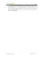
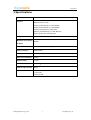
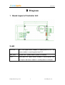
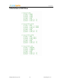
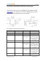
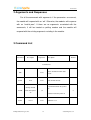
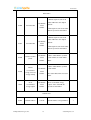
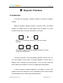
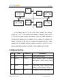
Smart Outlet
User Manual
.
LinkSprite Technologies, Inc
January, 2009
www.linksprite.com
Smart Outlet
Table of Content
Summary ..................................................................................................................3
1 Introduction............................................................................................................................3
2 Features ..................................................................................................................................5
3 Specifications .........................................................................................................................7
4 Applications ...........................................................................................................................8
Diagram....................................................................................................................9
1 Board Layout..........................................................................................................................9
2 LED........................................................................................................................................9
3 Definition of Pin...................................................................................................................10
4 Interface Card Socket Definition and Layout………………………………………………11
Command Interface................................................................................................13
1 Command Mode...................................................................................................................13
1.1 Enter command mode ...............................................................................................13
1.2 Exit command mode .................................................................................................13
2 Arguments and Responses ...................................................................................................14
2.1 Arguments and Responses………………………………………………………….14
2.2 Commands without Arguments.................................................................................14
2.3 Modified arguments ..................................................................................................14
3 Command List......................................................................................................................14
Repeater Function ..................................................................................................18
1 Introduction..........................................................................................................................18
2 Function Setting ...................................................................................................................19
2.1Start repeater function ................................................................................................19
2.2Turn off repeater function ..........................................................................................19
2.3 Setting Illustration.....................................................................................................20
3 Repeater Grade.....................................................................................................................20
Logic Address ........................................................................................................21
1 Logic Address ......................................................................................................................21
2 Address Setting ....................................................................................................................22
LinkSpriteTechnologies, Inc.
2
www.linksprite.com
Smart Outlet
Summary
1. Introduction
LinkSprite smart outlet system consists of one or more smart outlet
controller unit and one or more smart outlet. The smart outlet system can
be controlled by host (PC or MCU) through serial port using convent AT
commands. Smart outlet can be turned on/off, report real time power, and
report accumulated energy consumed remotely by LinkSprite powerline
communication technology.
A smart outlet controller unit works as gateway to communicate with
the remote smart outlets by powerline communication. On the smart outlet
controller motherboard, there is a 20-pin receptacle, users can choose
different daughter boards based on the interface needs. This 20-pin
receptacle is pin-compatible with Xbee module from Digi (www.digi.com).
So an Xbee module can also be used on smart outlet controller. Available
interface cards are UART-RS232 daughter board, UART-RS485 daughter
board, UART-USB daughter board, UART-Ethernet daughter board and
Zigbee.
The smart outlet controller can also be configured to transparently
move serial data over the powerline network, and achieves the target of
replacing cables by the ubiquitous powerline network.
All LinkSprite modules, including smart outlet controller and smart
outlet have the built-in packet-level repeater function. This feature can
greatly extend the coverage of the powerline communication.
LinkSpriteTechnologies, Inc.
3
www.linksprite.com
Smart Outlet
LinkSprite smart outlet controller and smart outlet have both physical
and logic addresses. In a network, both physical and logic addresses can
be used to address different nodes in the network, and can also broadcast
within the same domain.
LinkSpriteTechnologies, Inc.
4
www.linksprite.com
Smart Outlet
2 Features
A Smart Outlet Controller with a UART-RS232 daughter card
A Smart Outlet OEM board
•
Remote control and status (real time power consumption and
accumulated energy consumed) onitoring of outlets through powerline
and/or Zigbee communications
•
Built-in error correction codes.
•
Built-in repeater function to extend the coverage.
•
Physical and logic address
•
AT commands.
•
3.3V TTL UART, Optional RS232, RS485. USB, Ethernet, Zigbee
LinkSpriteTechnologies, Inc.
5
www.linksprite.com
Smart Outlet
interfaces
•
FSK
•
Low power (Peak Current During Transmission < 100mA, current
Frequency Shift Keying modulation used in physical layer
During Receiving < 50mA, Standby current < 30mA)
•
RoHS
•
Small module size (55mm X 85mm including the on-board power switch
regular keep out area), and easy to be implemented into existing
products.
LinkSpriteTechnologies, Inc.
6
www.linksprite.com
Smart Outlet
3 Specifications
Product name
Smart outlet, smart outlet controller
Interface
3.3V TTL UART
Optional interface cards:
RS232 (model/ordering no: UART-RS232)
RS485 (model/ordering no: UART-RS485)
USB (model/ordering no: UART-USB)
Ethernet (model/ordering no: UART-Ethernet)
Zigbee (model: Xbee from Digi.com)
Voltages
230VAC/50Hz, 110VAC/60Hz
Maximum Power Rating
2000W
of Outlet
Modulation
FSK
Frequency Shift Keying
Carrier frequency
262K/144KHz
Error Correction
FEC Forward Error Correction
Data rate on Powerline
30Kbps
Repeater Hops
3 Hops
Transmission distance
300 feets no repeater
Support nodes number
65535
LED
Power Line Activity LED
system LED
serial port LED
LinkSpriteTechnologies, Inc.
7
www.linksprite.com
4 Applications
Smart Outlet
•
AMR
•
Home automation
•
Industry manufacture and control
•
Safeguard, fire alarm, smoke alarm
•
Collect and transmit instrument data
•
Safeguard and monitor
•
Solar/Wind electricity generation system
LinkSpriteTechnologies, Inc.
8
www.linksprite.com
Smart Outlet
1
Diagram
Board Layout of Controller Unit
2 LED
PLC LED
PLC LED: green mans module is sending data to PLC; red
means module is receiving data from PLC
RDY_LED
System LED green means system is in normal
LED1
Serial port LED green means module is receiving data from
aerial port; red means module is sending data to serial port
LinkSpriteTechnologies, Inc.
9
www.linksprite.com
Smart Outlet
3 Definition of DIP Pins
LinkSpriteTechnologies, Inc.
10
www.linksprite.com
Smart Outlet
4 Interface Card Socket Definition and Layout
The pin layout of interface cards is compatible with Xbee module from Digi
(www.digi.com). The socket on the PLC-UART motherboard can be used to
receive any interface card with the pin out shown below:
Pin assignment of the interface card socket:
Pin #
Name
Direction
Description
1
VCC
-
3.3V Power supply
2
DOUT
Output
UART Data Out
3
DIN
Input
UART Data In
4
EX4
Depending on
Route daughtercard
model of daughter
final interface signal
card
back to mother board,
and to the DIP pins to
user’s board
5
RESET
Input
Module Reset
6
EX3
Depending on
Route daughtercard
model of daughter
final interface signal
card
back to mother board,
and to the DIP pins to
user’s board
7
EX2
Depending on
Route daughtercard
model of daughter
final interface signal
card
back to mother board,
and to the DIP pins to
user’s board
8
LinkSpriteTechnologies, Inc.
EX1
11
Depending on
Route daughtercard
model of daughter
final interface signal
www.linksprite.com
Smart Outlet
card
back to mother board,
and to the DIP pins to
user’s board
9
SLEEP
Input
Pin Sleep Control Line
10
GND
-
Ground
11
Unused
-
-
12
Unused
-
-
13
Unused
-
-
14
Unused
-
-
15
Associate
Output
Associated Indicator
16
Unused
-
-
17
Unused
-
-
18
Unused
-
-
19
Unused
-
-
20
Unused
-
-
LinkSpriteTechnologies, Inc.
12
www.linksprite.com
Smart Outlet
Command Interface
Smart Outlet controller can work as command center to the remote
smart outlet (command mode) and can also work as data modem to
transparent move user data between serial port and powerline network (data
mode). The default mode is command mode. The default mode after power
cycle can also be configured to be either command mode or data mode using
AT command.
1 Command Mode
1.1 Enter command mode
In data mode, the controller can be put into command mode by
sending “###” through serial port. The module will respond with an “ok”. In
order to prevent the situation where the user data” ###”mistakenly triggers
the command mode, there must be no serial port data input one second
before and after the receiving of "###". At the same time, the gap between
the three ”#” should not be more than one second, otherwise, it will be
considered as a data rather than a command.
1.2 Exit command mode
The only way is to input command “ATEX”. The controller will
response "exited".
LinkSpriteTechnologies, Inc.
13
www.linksprite.com
Smart Outlet
2 Arguments and Responses
For all the commands with arguments: if the parameters are correct,
the module will respond with an “ok”. Otherwise, the modules will response
with an “invalid para”. If there are no arguments associated with the
commands, it will be treated as polling modem and the module will
respond with the existing arguments residing in the module.
3 Command List
Command
Description
Arguments
Description
Default
Control Class
###
none
ATEX
Exit
none
mode after power
1,0
on
ATRS
Reset
LinkSpriteTechnologies, Inc.
mode
Exit command mode
1: Command mode after power
Change default
ATCM
Enter command mode in data
on
0
0: Data mode after power on
none
14
Software reset
www.linksprite.com
Smart Outlet
Outlet Class
If without argument, turn on all
Destination
ATON
Turn On Outlet
Serial
Number
outlets within the same logical
domain
If with argument, turn on the outlet
with the specified serial number
If without argument, turn off all
Destination
ATOF
Turn Off Outlet
Serial
Number
outlets within the same logical
domain
If with argument, turn off the outlet
with the specified serial number
ATPW
Poll the real time
power
Poll the
ATEG
accumulated
energy since last
energy clearing
ATEZ
Destination
Poll the outlet with the specified
Serial
serial number, the return will be
Number
Watts.
Poll the outlet with the specified
Destination
serial number
Serial
Number
The return will be W.h, instead of
kW.h.
Clear
Destination
accumulated
Serial
energy register
Number
Clear accumulated energy
register of the outlet with the
specified serial number
Network class
ATDA
Domain Address
LinkSpriteTechnologies, Inc.
1-32767
15
Domain Address of Logic Address
1
www.linksprite.com
Smart Outlet
ATNA
Node Address
1-65535
Node Address of logical address
1
Function class
ATRP
Repeater
Y,N
Relay function, Y is on, N for off
Y
A string with
ATNM
Name
length less
than 15
Set the name of the module
PU-R485A
Communication class
1200, 2400,
ATBD
Baud Rate
4800, 9600,
Baud Rate
9600
19200
ATDB
Data Bit
5,6,7,8
ATPA
Parity
N, O, E
ATST
Stop Bit
1,2
Data bit
Parity bit
8
N = no, O = odd, E =
even
Stop bit
N
1
Debug class
The raw data for debugging. The
module will output sent raw
ATRW
Raw
Y,N
packets from host to the module,
and not just the payload. Y means
N
turn on this function, N means
turning off.
LinkSpriteTechnologies, Inc.
16
www.linksprite.com
Smart Outlet
ATSR
Search
LinkSpriteTechnologies, Inc.
none
17
Search for peer module on the
power line network
www.linksprite.com
Smart Outlet
Repeater Function
1 Introduction
To extend the coverage, Linksprite modules have built-in repeater
function.
When the module'
s repeater function is turned on (off is the default
setting), the module echos the data packet from the power line, while
entertaining the data sent by host through the serial port.
A
C
Because of far distance, data transmission can not be
reached.
A
B
C
After adding repeater function to proper locations, the data
can be transmitted farther.
Transceiver function is not influenced by repeater function, that is to
say, each module can be used as a separate repeater or can be seen as
repeater when sending and receiving data. It can not only send and
receive data from the power line, but also repeat other data packets.
In order to prevent network congestion, the module is smart smart
enough to know the data were sent or repeated by itself and will discard
the data packets when receiving the duplicated ones.
LinkSpriteTechnologies, Inc.
18
www.linksprite.com
Smart Outlet
Note: Due to the fact that repeaters will resent the received data
packets, if the number of repeater is too large, a number of repeaters will
seize the channel, and lead to increased communication time. When
deploying the repeater, one should take full account of the balance of
reliability and real-time.
2 Function Setting
AT command ‘ATRP’ is designed to set up the repeater function.
2.1Turn on repeater function
Steps
input
response
description
1
+++
ok
Enter command mode
2
ATRP
Y or N
Poll current repeater status, Y is on,
N for off
3
ATRP Y
ok
Turn on repeater function
4
ATRP
Y
Check present repeat status, ON
5
ATEX
exit
Exit command mode
2.2Turn off repeater function
steps
input
response
description
1
+++
ok
Enter command mode
2
ATRP
Y or N
Check current repeater status, Y is
on, N for off
3
ATRP N
LinkSpriteTechnologies, Inc.
ok
Turn off repeater function
19
www.linksprite.com
Smart Outlet
4
ATRP
N
Check current repeater status, OFF
5
ATEX
exit
Exit command mode
2.3 Setting Illustration
Repeater function is available in the factory.
Once repeater function is modified; it will immediately take effect and be
preserved permanently, even if the module is restarted.
3 Repeater Hops
A data packet could at most pass through third repeater three times. It
is shown as follows
A
B
C
The
first
time
D
The
second
time
E
The
third
time
F
No
re-transition
Data packet is sent from module A to module B. From module B to
module C is the first time, to module D is the second time, and to module E
is the third time. Module F is the termination. Therefore, data packet won’t
be sent to module F.
LinkSpriteTechnologies, Inc.
20
www.linksprite.com
Smart Outlet
Logic Address
1 Logic Address
Module data packets are transmitted in the way of broadcasting in
power lines. All modules will receive the data packets issued by the
module and sent them, through the serial port under carrier signals area.
When multiple modules are installed on the same power line network,
however, one does not want them to communicate directly; thus, the
networks can be addressed by the logic address.
Logic address is composed of two parts: domain and nodes. For
example, the logic address (10:200) means that the domain value is 10,
node value is 200. Logic address is the default setting (1:1).
Module data packets can only be received and processed by the
module at the same domain. Other modules, even detecting the carrier
signal will not receive, nor to transmit to the serial port or repeater.
LinkSpriteTechnologies, Inc.
21
www.linksprite.com
Smart Outlet
A
1
1
B
10 8
H
10 8787
F
G
2002 65500
10
59
1
E
299
C
2002
1998
D
10 1000
On the above figure, A, E are at the same network, their domain
values are 1; B, D, F, H are at the same network, its domain values are10;
C, G are at the same network, their domain values are 2002. Although in
the physically speaking, all the modules are in a power line network, the
packet issued by A, will only be received and processed by E, other
modules will not respond. Similarly, packet issued by F, only B, D, H will
receive and process packet issued by F, other modules will not work.
2 Address Setting
step
input
response
description
1
+++
ok
Enter command mode
2
ATDA
1-32767
Check domain values of present
logic address. Default factory setting
is 1.
3
ATNA
1-65535
Check nodes values of present logic
address. Default factory setting is 1.
4
ATDA 2
ok
Set domain value of logic address as
2
LinkSpriteTechnologies, Inc.
22
www.linksprite.com
Smart Outlet
5
ATNA 45
ok
Set nodes of logic address as 45
6
ATDA
2
Check
domain
values
of
logic
address
7
ATNA
45
Check node values of logic address
8
ATEX
exited
Exit command mode
LinkSpriteTechnologies, Inc.
23
www.linksprite.com
Smart Outlet
LinkSprite Technolgies, Inc.
1410 Cannon Mountain Dr.
Longmont, CO 80503
(Voice) 720-9494-932
(Email) [email protected]
http://www.linksprite.com
LinkSpriteTechnologies, Inc.
24
www.linksprite.com