1
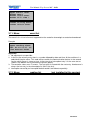
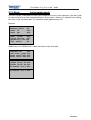
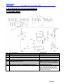
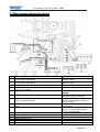
User Manual Top-Control MC - 04/08
______________________________________________________________________
Top-Control MC
Pool controller for free chlorine, pH, ORP
and Temperature for public pools
Part 2: Description of the controller TopControl MC
(Part 1:
- function of the GRANUDOS Top
- Installation and start up
- Trouble shooting and maintenance
Subject to any kind of alterations, errors exepted
User Manual Top-Control MC - 04/08
________________________________________________________________________________________________________________________________________________________________________
Table of contents
1.
2.
3.
3.1
3.1.1.
3.1.2.
3.1.3.
3.1.4.
3.1.5.
3.1.6.
3.2.
3.3.
3.4.
3.4.1.
3.5.
3.5.2.
3.6.
3.6.1.
3.7.
3.7.1.
3.8.
3.9.
3.10.
3.11.
3.12.
3.13.
3.14.
3.15.
3.16.
3.17.
3.18.
3.19.
3.20.
3.21.
3.22.
3.23.
3.24.
4.
5.
5.1
5.2
6.
7.
page
General description for user and safety notes
Description of function
The Main Menue
Menu: Justify
Menu: Justify Cl DPD (slope)
Menu: Justify Cl zero point
Menu: Justify pH Justify program
Menu: Justify pH Phenol red
Menu: Justify ORP justify program
Menu: Justieren Temperature adjustment
Menu: status progr.
Menu: dosing cycle
Menu: parameter chlorine
Menu: parameter chlorine DOS configuration
Menu: parameter pH
Menu: parameter pH DOS configuration
Menu: parameter ORP only alarm values
Menu: parameter ORP auto mode
Menu: parameter ORP DOS configuration
Menu: parameter flocculation
Menu: parameter flocculation DOS configuration
Menu: Filter disinfection
Menu: night values
Menu: Intrruption list
Menu: event list
Menu:reading list (not installed in this version)
Menu: test program inputs
Menu: test program outputs
Menu: dosing start delay (DOS blocked)
Menu: date
Menu: time
Menu: network (not installed in this version)
Menu: printer
Menu: system reset
Menu: adjust language
Menu: change passwort
Menu: MobilConnect (not installed in this version)
Menu: adjustment audible sound
Different indications on the display
Anschluss.- und Steckerbelegung
Processor board
Main measure and control board
Input connector description TopControl MC
Parameter list
3
4
5
6
6
6
7
8
9
9
10
10
11
13
14
15
16
17
18
18
19
20
21
23
24
24
25
26
26
27
27
27
27
28
28
28
28
29
29
31
31
32
34
36
2 von 37
User Manual Top-Control MC - 04/08
________________________________________________________________________________________________________________________________________________________________________
1. General description for user and safety notes
Please read the following safety notes before the installation and use of the dosing equipment. To
disregard the safety notes could lead to personnel injury or property damage as a result.
Attention!
-
l
Avoid personnel injury by electrical power, please ensure that only qualified personnel install
the equipment and takes the machine into service.
Please observe the national rules for the electrical installation.
-
Please observe the rules of working with chemicals. Observe the datasheets of the chemical
supplier. Don’t mix chemicals. Wear personal protective clothing.
-
Change of the dosing equipment and improper use is inadmissible.
-
The dosing equipment consists of some safety functions against overdosing. E.g. flow monitoring circulation water monitoring (option) dosing time limit, reading value alarms. Only if
these monitoring functions work properly and were not switched off, a proper and stable function is guaranteed.
Attention!
l
-
Please check periodically the parameters free chlorine, pH and ORP to ensure the national
health regulation.
-
Keep unauthorized people away from dosing equipment. Wrong adjustments can lead to
chemical overdosing.
-
To ensure extended life please check the dosing equipment periodically and perform all necessary maintenance work.
The TopControl MC can be used for different dosing equipments. The configuration for
Granudos10 Top-MC, Granudos45 Top-MC, Granudos100 Top-MC or TopControl 2S has
been factory adjusted. Don’t change these adjustments for a proper use.
3 von 37
User Manual Top-Control MC - 04/08
________________________________________________________________________________________________________________________________________________________________________
2. Description of the function
With the controller TopControl MC you can measure the parameters of hygiene free chlorine, pH,
ORP and temperature.
To use the controller we have provided a simple to use “adjuster wheel switch knob”. The adjustment
wheel has two functions. To turn the wheel changes the selected menu and changes the selected
parameters. To press the wheel enters the selected menu or confirm the changes.
Important!
In the description below we call the turning function of the adjustment wheel only WHEEL and the
press function to confirm only ENTER
2.1. Display shown in the automatic mode:
mg/l
pH Auto
0%
0% start
14:12 Mo 02.12.05
DOS blocked:
11:22
Cl - pH control, Status AUTO mode
0% = no dosing (dosing lock) start up mode
Time, weekday, date
Dosing lock 11 minutes and 22 seconds
Stop dosing lock by ENTER.
mg/l
80%
14:16
pH Auto
55%
Mon 02.12.05
Cl - pH control, status AUTO mode
80% = difference to set value (calculated dosing value)
Time, weekday, date
No interruption
Start main menu by ENTER. (main menu see next page)
2.2. Programming of parameters
There are three levels to change parameters. To change parameters you have to type in a password.
The password releases the change of parameters in different levels.
Attention:
You have to type in the password only once. Then it is valid until you leave the menu. To change the
level of access, you have to leave the menu and go in again.
Password input >
15
TOPCONTROL guestmode
The adjustments are
limited. Plese confirm by ENTER
Mit ENTER bestätigen
- Operator
normal access
- Password: 15 (factory, adjustable)
(Change of some parameters, e.g. calibration is released)
- Guest access minimum access
- No password for this level press ENTER with any value
(E.g. change of date, time und calibration is possible)
The service password is only for qualified authorised personnel and you will get it only on request. In
the service access mode you can change every parameter.
With the service password you can change the password for operator and service. See password
menu in the manual. For access authorisation see manual section.
You have to in type the password only once. Then it is valid until you leave the menu. To change the
level of access, you have to leave the menu and get in again.
4 von 37
User Manual Top-Control MC - 04/08
________________________________________________________________________________________________________________________________________________________________________
Important!
Until the dosing start delay is released there is no automatic change in the bottom line. After dosing
start delay every second the bottom line is scrolled automatically.
Additionally the bottom line is scrollable by WHEEL. The indication is switched to: dosing time delay
(if active), interruption message (if active), interruption messages (if active), buffer filling messages (if
active), start mode message (if active). If there is no mode listed above the bottom line is cleared.
If the dosing start delay is active and ENTER is pushed, first the counter for the dosing start delay is
shown in the bottom line. The second push de-activates the dosing start delay once (set to zero). The
next push starts the menu. If the dosing start delay is not running, the first push starts the menu.
3. The main menu
Detailed menu description on the following pages
>back to auto mode
>justify
>status progr.> Auto
>DOS cycle
> 30 s
>parameter
>parameter
>parameter
>parameter
chlorine
pH
ORP
flock
>filter disinfection
>night values
>interruption list
>event list
>reading list
>test inputs
>test outputs
>DOS blocked >10min
>date
Son 01.11.05
>time
>13:38
>network
>printer
>system reset
>lang.
>Deutsch
>change password
>MobilConnect
>audible sound>on
>audible sound>on
Reset counter:
5
Time meter:
1h
The time meter and start counter is only shown in the service access mode. The start counter stores (increments by one) every
power supply disconnection of the controller
5 von 37
User Manual Top-Control MC - 04/08
________________________________________________________________________________________________________________________________________________________________________
3.1 Menu:
justify
>back
(justify)
>Cl DPD1
>Cl zero point
>pH justify program
>pH Phenol Red
>ORP justify program
>temperature adj.
3.1.1. Menu:
justify
Cl DPD1 (slope)
>back
(01.11.05)
>input
DPD1> 0.63
Cl current
6.30µA
Flow on
Important!
The Cl current must be higher 3 µA and lower 100 µA.
The bottom line indicates the status and the error messages.
The flow must be on in the DPD1 justify mode.
Type of error
error message in the bottom line
flow is off
flow off is shown flashing
the justify function is blocked
Cl current < 3 µA
reading too small is shown
the justify function is blocked
Cl current > 100 µA
reading too large is shown
the justify function is blocked
(Changes in the flow status and reading values lead to an interruption of the justify function)
How to change:
1. Select the line input DPD1 and confirm with ENTER , adjust the Chlorine value into the DPD1
value by WHEEL and confirm with ENTER.
2. In the top line on the right side now the justification date is shown.
3.1.2. Menu:
justify
Cl zero point
>back
(01.11.05)
>input
Zero> 0.09
Cl current
0.92µA
Flow off
Important!
The flow must be off for min. 5 minutes!
The bottom line indicates the status and the error messages.
The Cl current must be below 3 µA.
The flow must be off in the zero point justify mode.
Type of error
error message in the bottom line
flow is on
flow on is shown flashing
the justify function is blocked
Cl current > 3 µA
reading too large is shown
the justify function is blocked
(Changes in the flow status and reading values lead to a interruption of the justify function)
How to change:
1. Select the line input zero and confirm with ENTER . Adjust the value to zero (don’t pay attention on the sign, could be negative when you start). Confirm with ENTER.
2. In the top line on the right side now the justification date is shown.
6 von 37
User Manual Top-Control MC - 04/08
________________________________________________________________________________________________________________________________________________________________________
3.1.3. Menu:
justify
Set zero and slope
To defaults before
You start to justify
Reset values >yes
pH justify program
Attention:
When you start the pH justify program, there is no automatic parameter
reset of slope and zero to defaults. (Standards: zero point pH7.0 = 0mV
& slope ca. –59mV/pH).
If you confirm yes by ENTER, zero point and slope would be reset to
defaults. If you change by WHEEL to no and confirm by ENTER no default reset is performed.
How to change:
1. Close inlet measuring valve
2. Select >pH justify program in the main menu and confirm with ENTER.
3. Press ENTER again to load the defaults (we recommend).
>back
(01.11.05)
>pH 7.00
>pH ---->pH x.xx
>pH ----stat: wait
94.7mV
4. In the top line the last justify date is shown on the right.
5. Remove the ph probe from the acrylic flow cell and wash it only with water. Start always with
the zero buffer solution (pH 7.00). The buffer is recognized automatically. As long as the
buffer is not recognized the status wait is shown in the bottom line. There is a voltage value
shown in the bottom line on the right. This is the direct reading of the pH probe. The reading
for zero (pH 7,0) must be between ±50 mV.
6. Wait until the counter behind stat: is zero (reading was stable over 30 seconds). If there is a
change of more than pH 0.10 the counter is reset to 59. When the counter is zero the indicated reading value is set to zero (pH 7.00) automatically and the zero value to correct the
reading is stored. After that the message ok is shown after pH 7.00 in the display. To speed
up this process press ENTER . Pay attention that the reading is stable for min. 30 seconds.
>back
(01.11.05)
>pH 7.00
>pH 7.15
>pH x.xx
>pH ----stat:
26 - 14.7mV
The buffer solution pH 7.00 is recognized (range: 6.15 – 7.85).
7. Wash the pH probe accurately again and put it into the second buffer solution pH 4.00
>back
(01.11.05)
>pH 7.00 ok>pH ---->pH 4.00
>pH 4.58
stat:
55
155.8mV
The buffer solution pH 4.0 is recognized (range: 3.15 – 4.85)
8. Wait until the counter behind stat: is zero (reading was stable over 30 seconds). If there is a
change of more than pH 0.10 the counter is reset to 59 again. When the counter is zero the
indicated reading value is set to recognized buffer value (pH 4.00) automatically and the slope
value to correct the reading is calculated and stored. To speed up this process press ENTER .
Pay attention that the reading is stable for min. 30 seconds.
If the counter is reset to 59 because of reading changes above pH 0.1 more than 50 times, you’ll get
an error message and the justification is interrupted. The values zero and slope will be not stored in
this case. You have to confirm this message by ENTER
Please check if the pH probe is worn out, the connectors (corroded) the cable (could be broken) or
the buffer solution (polluted)
7 von 37
User Manual Top-Control MC - 04/08
________________________________________________________________________________________________________________________________________________________________________
If you perform the zero calibration first (ok is indicated after the in the second line after pH 7.00) than
the justification is finished after the slope calibration automatically.
There is short message shown in the fourth line not necessary to confirm by ENTER.
menu pH Justify
val.:
- 14.7mV
slope val:mV/pH 52.8
accept
>yes
Important!
If the zero value is out of range (±50mV) and/or the slope value is out of range (55 – 65 mV/pH) the
confirmation procedure is interrupted by an error message and the original values before justification
will be maintained.
attention
pH electrode failure
too slow reaction
please exchange
Please check if the pH probe is worn out, the connectors (corroded) the cable (could be broken) or
the buffer solution (polluted)
3.1.4. Menu
Justify
pH Phenol Red
This menu is only for adjusting the pH reading to the reading you get with the Phenol Red test tablet
method.
Remark!
The two point calibration is the more accurate way for pH calibration. This method is preferred if possible instead of the Phenol Red method.
>back
(12.10.05)
>reading pH > 7.45
adjustment pH 0.00
(range
pH +/-0.20)
How to change:
1. Select the line reading pH and press ENTER , adjust the indicated reading to the readings
you’ve got by the Phenol Red method by WHEEL. Confirm with ENTER.
2. The justification date is shown in the top line on the right.
Important!
1. The adjustment range is limited to pH ±0.20 . The actual adjustment value is shown in the third
line on the right.
2. If there is a bigger difference between the reading and the Phenol Red value, please check
the reason before you start to adjust.
Please check if the pH probe is worn out, the connectors (corroded) the cable (could be broken) or
the buffer solution (polluted)
8 von 37
User Manual Top-Control MC - 04/08
________________________________________________________________________________________________________________________________________________________________________
3.1.5. Menu:
Justify
ORP justify program
>back
(02.08.05)
>reading
> 470mV
adjustment
0mV
debit:
475+/-30mV
How to change:
1. Shut the measure water valve. Remove the ORP electrode from the bottom of the acrylic flow
cell and screw it into the ORP check cylinder. Remove also the pH probe from the flow cell
and put it into the check cylinder from the top. Fill the ORP buffer solution (475mV) into the
check cylinder. Both electrodes (pH and ORP) must be connected to the controller!
2. Select the line reading and press ENTER , adjust the reading value to the value of the ORP
buffer solution (shown on the bottle) and confirm with ENTER .
3. The adjustment date is shown in the top line on the right.
Important!
1. Attention! The ORP buffer solution is irritating! Avoid skin contact.
2. The adjustment is limited in the range ± 30mV . The actual adjustment value is shown in the
third line on the right.
3. After a pH probe replacement, an ORP justification is necessary too.
3.1.6. Menu:
Temperature adjustment
>back
(05.04.05)
>Temperature > 29°C
How to change:
1. Select the line temperature and press ENTER, adjust the reading value to the temperature
value you’ve got by an external temperature measurement system and confirm with ENTER.
2. The adjustment date is shown in the top line on the right.
Important!
1. The adjustment is limited in the range of ± 10°C .
9 von 37
User Manual Top-Control MC - 04/08
________________________________________________________________________________________________________________________________________________________________________
3.2. Menu:
status progr.
>back to auto mode
>justify
>status progr. >AUTO
>DOS cycle
> 30 s
Program modes :
Default value:
AUTO AUTO
MANU OFF
AUTO: automatic mode including measurement, proportional dosing and monitoring of reading alarms
based on the adjustments in the menu.
MANU:Emergency program e.g. if the probes were out of order. The readings and proportional control adjustments in the menu are not taken into consideration for the dosing. The dosing is continuously, controlled only by the values dosing amount (pH and chlorine) and dosing cycle.
You have to select the dosing amounts for the pool dimensions manually.
All reading alarms are de-activated!
Please check the water parameters (free chlorine and pH) manual periodically and more often!
OFF: The complete controller is de-activated including dosing and reading alarms!
3.3. Menu:
dosing cycle
>back to auto mode
>justify
>status progr. >AUTO
>DOS cycle
> 30 s
Upper limit:
Lower limit:
Adjustment steps:
Default value:
600 seconds
30 s
30 s
30 s
(standard)
The dosing cycle is the adjustable time for the length of the periodical dosing. A dosing cycle of 30s is
divided into the following parts and dosing is always in the 1st 30 seconds of the set dosing cycle.
The maximum time for chlorine dosing is 15 seconds, the actual dosing time depends on the difference between set value and chlorine reading; the dosing time is shorter if the difference is smaller indicated by the indicated percentage value for Cl.
After the chlorine dosing cycle (15 sec) there is a fixed rest of 4s.
Next the dosing cycle for pH (acid) is active. The maximum time for acid dosing is 7.5 seconds, the
actual dosing time depends on the difference between set value and pH reading, the dosing time is
shorter if the difference is smaller indicated by the indicated percentage value for pH.
After the acid dosing cycle (7,5 sec.) there is another fixed rest of 3.5s.
The rest of the set cycle time (DOS cycle) is pause without dosing – dosing only in the 1st 30 seconds.
The
Important!
1. The maximum dosing amount you’ll get only with the shortest dosing cycle (30s)
An increase of the dosing cycle reduces the maximum amount of dosing.
2. If the dosing cycle is too large it is possible, that the dosing amount is not enough to supply
the required chemicals (e.g. chlorine) into the pool. In this case reduce the dosing cycle.
3. If the dosing cycle is too small, the dosing amount may be too high and overdosing is possible.
10 von 37
User Manual Top-Control MC - 04/08
________________________________________________________________________________________________________________________________________________________________________
3.4. Menu:
parameter chlorine
>back
(Cl params)
>set value
>0.60
>prop. range
>0.20
>DOS amount
> 500
Set value:
Upper limit:
Lower limit:
Adjustment steps:
Default value:
3.00 mg/l
0.10 mg/l
0.05 mg/l
0.60 mg/l
(1.5 ppm = U.K. standard)
Proportional range:
Upper limit:
1.00 mg/l
Lower limit:
0.05 mg/l
Adjustment steps:
0.05 mg/l
Default value:
0.20 mg/l
(standard)
Dosing amount:
Upper limit:
the max. dosing depends on the adjustments DOS configuration
Lower limit:
100 g/h
Adjustment steps:
10 g/h
Default value:
no value
Important!
If there is a change in the menu DOS configuration this parameter is set to the maximum dosing
amount.
>upper alarm
>0.80
>lower alarm
>0.40
>time monitoring >30
>cycle monitoring> 5
Upper alarm:
Upper limit:
Lower limit:
Adjustment steps:
Default value:
5.00 mg/l => off (Alarm de-activated)
set value + 0.10 mg/l
0.05 mg/l
0.80 mg/l
(1.0 ppm = U.K. standard)
Lower alarm:
Upper limit:
Lower limit:
Adjustment steps:
Default value:
set value - 0.10 mg/l
0.00 mg/l = off (Alarm de-activated)
0.05 mg/l
0.40 mg/l
(1.0 ppm = U.K. standard)
Important!
If you change the set values the input cursor jumps after you confirm the change directly to the alarm
value adjustment. In this case you have to select the alarm values.
Time monitoring:
Upper limit:
Lower limit:
Adjustment steps:
Default value:
60 min
1 min
1 min
30 min
(standard)
11 von 37
User Manual Top-Control MC - 04/08
________________________________________________________________________________________________________________________________________________________________________
Cycle monitoring:
Upper limit:
Lower limit:
Adjustment steps:
Default value:
20
1
1
5
(standard)
The TopControl MC consist of a dynamic dosing time monitoring. The readings are monitored periodically (time monitoring) and compared with the reading of the cycle before. If there is no change of
the reading triggered by the dosing of chlorine (in the right direction reading is higher than before)
a cycle counter is decreased by one (cycle monitoring). If the cycle counter is zero, an alarm is performed, the chlorine dosing stops and an alarm message (dyn. DOS alarm Cl) is shown in the bottom
line.
Important!
The only possibility to clear a dynamic dosing alarm is to start the menu interruption list or a restart of the controller.
>basic dosing
>off
>buffer filling >off
>DOS configuration
Basic dosing
Upper limit:
Lower limit:
Adjustment steps:
Default value:
25 %
0 % = off
1%
off
(standard)
The basic dosing is an additional possibility to solve problems with the pool circulation. In normal proportional dosing procedure, dosing is only if there is a difference between set value and reading. If
the pool circulation is well the readings always will be near the set value. But if the circulation is poor,
there is the high probability for ups and downs in the readings. To make dosings and readings more
continuous, in that case we add to the proportional dosing the “basic dosing” amount. This amount is
added to every dosing performed in the active dosing cycle of the controller.
Example: dosing amount 500g/h; basic dosing 5%
25g/h will be added in every dosing cycle to the calculated amount of the proportional controller.
If there is a difference calculated by the proportional controller of 12 %, this value is added and shown
in the display 17% until the set value is get.
Important!
Don’t adjust too much basic dosing. An overdosing is possible if there is no bathers load in the
pool.
Buffer filling:
Upper limit:
100 %
Lower limit:
50% - < 49 % = off
Adjustment steps:
1%
Default value:
off
For the buffer tank filling you need a high dosing power to get high concentration of chlorine in the
buffer tank. That is he reason for a min. dosing power of 50%.
Important!
1. If you change a parameter in the DOS configuration, this parameter is set to off .
2. To release the buffer filling (output Y8) this value must be above 50%.
12 von 37
User Manual Top-Control MC - 04/08
________________________________________________________________________________________________________________________________________________________________________
3.4.1. Menu:
parameter chlorine
DOS configuration
For the GRANUDOS Top-MC (type 10, 45 & 100) are changes of the dosing amount possible:
>back
(Cl config)
>D-motor 1/min >12
>D-worm
mm >19
DOS amount g/h: 500
D-motor 1/min:
Adjustments:
Default value:
12
12
35
D-worm mm :
Adjustments:
Default value:
19
19
26
60
(three speeds available)
(two worm screw sizes are available)
Theoretical comtankations = dosing amount (amount is rounded!)
12 1/min + 19 mm = 500 g/h
(standard configuration Granudos10 Top-MC)
12 1/min + 26 mm = 1000 g/h
35 1/min + 19 mm = 1000 g/h
35 1/min + 26 mm = 2000 g/h
(standard configuration Granudos45 Top-MC)
60 1/min + 19 mm = 2000 g/h
60 1/min + 26 mm = 5000 g/h
(standard configuration Granudos100 Top-MC)
For TopControl-MC 2S ( with peristaltic dosing pumps) are following adjustments possible:
>back
(Cl config)
>pump 1/min
>80
>tube set
>3.2
DOS amount ml/h:1250
Pump 1/min:
Adjustment:
Default value:
80
80
Tube set mm:
Adjustment:
Default value:
0.8
3.2
(only one transmission grade available)
1.6
3.2
4.8
(four tube diameters available)
Possible comtankations = dosing amount (amount is rounded!)
80 1/min + 0.8 mm = 200 ml/h
80 1/min + 1.6 mm = 700 ml/h
80 1/min + 3.2 mm = 2500 ml/h
80 1/min + 4.8 mm = 6000 ml/h
Important!
1. The dosing amount indicated in the controller is only correct, if the selected parts (motor,
worm, dosing tube) have been installed and typed in correctly!
2. A change of the selectable parts lead to a change of the dosing amount shown in the bottom
line of the menu.
3. If you leave the menu with a change of the dosing amount, the buffer filling is switched off, the
values for filter disinfection will be set to defaults and the adjustable dosing amount in the
menu (value for manual dosing) is set to the max. value. If these features are active, you have
to adjust these parameters.
13 von 37
User Manual Top-Control MC - 04/08
________________________________________________________________________________________________________________________________________________________________________
-dosing
-buffer
-filter
changed
amount
re-fill
disinfection
please ENTER
3.5. Menu:
A message is shown in the display. Confirm by
ENTER.
The corresponding dosing amounts have to be adjusted again.
parameter pH
>back
(pH params)
>set value
>7.20
>prop. range
>0.20
>DOS amount
>1250
Set value:
Upper limit:
Lower limit:
Adjustment steps:
Default value:
pH
pH
pH
pH
8.00
6.00
0.05
7.20
(7.40 UK standard)
Prop. range:
Upper limit:
pH 1.00
Lower limit:
pH 0.05
Adjustment steps:
pH 0.05
Default value:
pH 0.20
DOS amount:
Upper limit:
the max. dosing amount depends on the DOS configuration adjustments
Lower limit:
100 ml/h
Adjustment steps:
10 ml/h
Default value:
no value
Important!
If you change parameters in the DOS configuration the adjustable dosing amount is set to the max.
dosing amount.
>upper alarm
>0.80
>lower alarm
>0.40
>time monitoring >30
>cycle monitoring> 5
Lower alarm:
Upper limit:
Lower limit:
Adjustment steps:
Default value:
pH 9.00 = off (Alarm de-activated)
set value + 0.10
pH 0.05
pH 8.00
Upper alarm:
Upper limit:
set value – 0.10
Lower limit:
pH 5.00 = off (Alarm de-activated)
Adjustment steps:
pH 0.05
Default value:
pH 6.40
Important!
If you change the set value, the alarms are influenced. After you confirm by ENTER the cursor jumps
to the alarm values automatically. Change the values if needed.
14 von 37
User Manual Top-Control MC - 04/08
________________________________________________________________________________________________________________________________________________________________________
Time monitoring:
Upper limit:
Lower limit:
Adjustment steps:
Default value:
60 min
1 min
1 min
30 min
Cycle monitoring:
Upper limit:
Lower limit:
Adjustment steps:
Default value:
20
1
1
5
>basic dosing
>off
>buffer filling >off
>DOS configuration
Basic dosing:
Upper limit:
Lower limit:
Adjustment steps:
Default value:
25 %
0 % = off
1%
off
Buffer filling:
Upper limit:
Lower limit:
Adjustment steps:
Default value:
100 %
< 49 % = off
1%
off
See basic dosing chlorine page 12
(Don’t use in the UK)
At buffer tank filling the acid dosing is to neutralize the chlorine solution. At taking into service the
buffer filling, the needed acid amount must be adjusted to get a pH of 7,00 +/- 0,2.
The minimum amount of the buffer filling must be 50%.
Important!
1. If any parameter in the menu DOS configuration is changed, the buffer filling is set to off.
2. The release the buffer re-filling (output Y8) the value must be above 50%.
3.5.2. Menu:
parameter pH
DOS configuration
>back
(pH config)
>pump 1/min
>80
>tube set
>3.2
DOS amount ml/h:1250
Pump 1/min:
Adjustment:
Default value:
80
80
Tube set mm:
Adjustment:
Default value:
0.8
3.2
fixed value
(only one speed available)
1.6
3.2
(four tube sets available)
4.8
15 von 37
User Manual Top-Control MC - 04/08
________________________________________________________________________________________________________________________________________________________________________
Possible comtankations = dosing amount (dosing amounts are rounded!)
80 1/min + 0.8 mm = 100 ml/h
80 1/min + 1.6 mm = 350 ml/h
80 1/min + 3.2 mm = 1250 ml/h
80 1/min + 4.8 mm = 3000 ml/h
Important!
1. Ensure that the installed parts are typed in correctly.
-dosing amount
2. A change of the parameters in the menu DOS configuration
-buffer filling
changes the dosing amount. If you leave the DOS configuration
-filterdisinfection
menu with a change the buffer filling is set to off, the values for
filter disinfection are set to defaults and the adjustable dosing
Changed please ENTER
amount is set to the max. dosing amount.
A message is shown on the display and has to by confirmed by ENTER .
Re-adjust the changed parameters.
3.6. Menu:
parameter ORP
You can use the ORP readings for monitoring the chlorine dosing only or to control the chlorine dosing e.g. if free chlorine measuring cell fails. In the case that ORP is only used for
alarm, only these values may be set. If ORP is used for chorine dosing control, the dosing
parameters have to be set too.
Menu:
parameter ORP
(only alarm values)
>back
(ORP params)
>Status >AL values
>upper alarm
> 820
>lower alarm
> 600
Status:
Upper limit:
AL values
auto mode
Default value:
AL values
Important
If you change the status, the set value and the alarm values will be set to defaults.
Upper alarm:
Upper limit:
Lower limit:
Adjustment steps:
Default value:
= 1000 mV = off (Alarm de-activated)
lower alarm value
10 mV
820 mV
Lower alarm:
Upper limit:
Lower limit:
Adjustment steps:
Default value:
upper alarm value
= 400 mV = off (Alarm de-activated)
10 mV
600 mV
16 von 37
User Manual Top-Control MC - 04/08
________________________________________________________________________________________________________________________________________________________________________
Menu:
parameter ORP
auto mode
The status auto mode is only an emergency mode if the chlorine probe is out of order. The ORP value
is used to get the free chlorine value indirectly.
Please check the free chlorine value in this mode more often!
>back
(ORP params)
>status >auto mode
>upper alarm
> 820
>lower alarm
> 600
Upper alarm
Upper limit:
Lower limit:
Adjustment steps:
Default value:
> 1000 mV = off (Alarm de-activated)
set value + 20 mV (set value see next window)
10 mV
820 mV
Lower alarm:
Upper limit:
Lower limit:
Adjustment steps:
Default value:
set value – 20 mV (set value see next window)
400 mV = off (alarm de-activated)
10 mV
600 mV
Important!
If you change the set value, the alarms are influenced. After you confirm by ENTER the cursor jumps
to the alarm values automatically. Change the values.
>time monitoring >30
>cycle monitoring>10
>set value
> 750
>prop. range
> 100
Time monitoring:
Upper limit:
Lower limit:
Adjustment steps:
Default value:
Cycle monitoring:
Upper limit:
Lower limit:
Adjustment steps:
Default value:
Set value:
Upper limit:
Lower limit:
Adjustment steps:
Default value:
Prop. Range:
Upper limit:
Lower limit:
Adjustment steps:
Default value:
60 min
1 min
1 min
30 min
20
1
1
5
1000 mV
500 mV
5 mV
750 mV
100 mV
10 mV
10 mV
100 mV
17 von 37
User Manual Top-Control MC - 04/08
________________________________________________________________________________________________________________________________________________________________________
>dosing amount > 500
>basic dosing >aus
>buffer filling>aus
>DOS configuration
Dosing amount
see chlorine adjustments
Basic dosing:
Upper limit:
Lower limit:
Adjustment steps:
Default value:
25 %
0 % = off
1%
off
Buffer filling:
Upper limit:
Lower limit:
Adjustment steps:
Default value:
100 %
49 % = off
1%
off
Important!
1. If you change a parameter in the DOS configuration, this parameter is set to off .
2. To release the buffer filling (output Y8) this value must be above 50%.
3.6.1. Menu
parameter ORP
DOS configuration
See DOS configuration chlorine, details -> see DOS configuration chlorine
Important!
Changes in the ORP menu change the adjustments of chlorine dosing!
3.7. Menu:
parameter flocculation
>back
(Flock)
>Flock >off
>amount
ml/m3>0.30
>circulat. m3/h> 100
>back
(Flock)
>Flock >on
30ml/h
>amount
ml/m3>0.30
>circulat. m3/h> 100
Flock:
Adjustments:
Default value:
off
off
on
Important:
If flocculation is off, no dosing amount is indicated.
If flocculation is on, the actual dosing amount is shown in the second line on the right. After you have
confirmed this value by ENTER this dosing amount is valid for flocculation. The indicated dosing
amount is calculated depending on the value amount (ml/m³) and pool circulation (m³/h).
18 von 37
User Manual Top-Control MC - 04/08
________________________________________________________________________________________________________________________________________________________________________
Amount:
Upper limit:
1.50 ml/m³
Lower limit:
0.10 ml/m³
Adjustment steps:
0.01 ml/m³
Default value:
0.30 ml/m³
The amount necessary for your bathing load is given by the manufacturer of the flocculation liquid.
Adjust here the specific amount for your pool, each pool can be different. Any change to these parameters influences the dosing amount.
Circulation:
Upper limit:
Lower limit:
Adjustment steps:
Default value:
1000 m³/h
10 m³/h
5 m³/h
100 m³/h
Important!
If the max. amount given by the Flock configuration (pump and tube set) is higher than the displayed amount, the display flashes. If you confirm this value, the dosing amount is set to the maximum dosing amount automatically. This value is valid for the flocculation
>DOS configuration
3.7.1. Menu:
parameter flocculation
DOS configuration (service code !)
Important!
If the max. amount given by the Flock configuration (pump and tube set) is higher, than the amount
in the display flashes. If you confirm this value, the dosing amount is set to the maximum dosing
amount automatically.
>back
(FLOCK)
>pump 1/min
>80
>tube set
>0.8
DOS amount ml/h: 100
Pump 1/min:
Adjustment:
Default value:
80
80
fixed value
(only one transmission speed available)
Tube set mm:
Adjustment:
0.8
1.6
3.2
4.8
Default value:
3.2
(four tube sets available)
Possible combinations = dosing amount (dosing amounts are rounded!)
80 1/min + 0.8 mm = 100 ml/h
80 1/min + 1.6 mm = 350 ml/h
80 1/min + 3.2 mm = 1250 ml/h
80 1/min + 4.8 mm = 3000 ml/h
Important!
1. Ensure that the installed parts are selected and entered in correctly.
2. A change of the parameters in the menu DOS configuration changes the dosing amount. If
you leave the DOS configuration menu with a change, the value amount and circulation need
to be changed.
19 von 37
User Manual Top-Control MC - 04/08
________________________________________________________________________________________________________________________________________________________________________
3.8. Menu:
filter disinfection
>back (filterdisin)
>status >off
>start
>Di >20:30
>period
> 20min
Status:
Adjustments:
Default value:
off
off
external
unique
weekly
off:
The automatic filter disinfection is de-activated.
external:
The filter disinfection is in the external mode. There is an external input. If this input is
active, the filter disinfection is started as long as this input is active. The dosing (pH
and Cl) starts at once independent on the dosing start delay with the adjusted dosing
amounts in this menu.
unique:
top up chlorine TUC. The dosing is started at once at the adjusted time and date
with the adjusted dosing amounts
weekly:
top up chlorine TUC. Once a week the dosing is started at the adjusted time and
date with the adjusted dosing amounts
Important!
1. For a time based TUC it is important that time and date is typed in correctly. The dosing duration and the dosing amount have to be selected to the pool dimensions!
2. If there was a change in one of the Dos configuration menus (pH, Cl, ORP) the status is set
to off. The dosing amounts are set to defaults.
3. If the status is set to external the values start and period are set to auto after confirmation
by ENTER. In the top line TUC is replaced by filterdisinf. The output Y4 for the 3/2-way control valve is active as long as the external input is active. The 3/2-way control valve is used to
switch the direction of the dosing from tapping point after filter to before filter
4. If the status is set to unique or weekly , a TUC is performed. In the top line on the right TUC
is shown.
5. If the status is set to unique , after the TUC period the status is set to off automatically.
6. The TUC starts only if the controller is in the automatic mode in the beginning of the set start
time.
7. If you start the menu and the TUC is active, the TUC is interrupted.
Start:
Adjustments:
Default value:
Mon – Sun, 0:00 – 23:59
Tue, 20:30
Period:
Upper limit:
Lower limit:
Adjustment steps:
Default value:
240 min
1 min
1 min
20 min
20 von 37
User Manual Top-Control MC - 04/08
________________________________________________________________________________________________________________________________________________________________________
After the TUC normally the readings for free chlorine and for ORP too are above the set alarm values.
In the next window alarms may be switched off.
>VAL AL after >auto
>top up cl with
>
10g/h chlorine
>
10ml/h acid
Value alarm after
Upper limit:
99 h
Lower limit:
0 h = auto
Adjustment steps:
1h
Default value:
auto
Important!
1. In the mode auto after the filter disinfection or TUC the start mode is active, no reading value
alarms until the readings are in the proportional range once.
2. If you use the time depending TUC the reading value alarms are de-activated during the adjusted
period. The time left for the TUC is indicated in bottom line. After the period the reading value
alarms are active without delay.
Filter disinfection/top up Cl (TUC) dosing amount with:
Upper limit:
Cl
max. dosing amount (see DOS configuration Cl)
acid
max. dosing amount (see DOS configuration pH)
Lower limit:
Cl
10 g/h
acid
10 ml/h
Adjustment steps:
10 g/h / 10 ml/h
Default value:
10 g/h / 10 ml/h
Important!
1. If the filter disinfection/TUC is active with 10mg/h / 10ml/h 1% for the dosing is shown.
2. If there is a change of any parameter in the menus of DOS configuration (pH, Cl, or ORP) to
dosing amount values will be set to defaults.
3.9. Menu:
night values
In the menu night values it is possible to reduce the set values for free chlorine and floccuation to
reduce the need of chemicals in the unused periods of the pool. The night values are only active, if
the ORP reading values are in a valid range (adjustable) to keep the pool under valid and clean conditions.
>back (night values)
>status >off
>Cl set value > 0.30
>flock set on > 50%
Status:
Adjustments:
off
on
Default value:
off
Important:
1. After a default reset, the status is always off.
2. If the night value mode is on , the controller activate this mode at any time in the adjusted period even after you left the menu or a TUC e.g. has been performed in this period. Please pay
attention that the night value mode will be activated with a delay, depends on a counter in
background. It is possible that it takes one Minute after you left the menu e.g. before the night
value mode is active.
3. The night value mode is shown in the second line on the right on the display.
21 von 37
User Manual Top-Control MC - 04/08
________________________________________________________________________________________________________________________________________________________________________
4. If the controller status is off, the night mode is blocked
Cl set value:
Upper limit:
5.00 mg/l
Lower limit:
0.10 mg/l
Adjustment steps:
0.05 mg/l
Default value:
0.30 mg/l
Important!
1. The reading value alarms are not changed in this mode. The standard reading value alarm is
active over the night.
2. There is no adjustment limit for the set value. So it is theoretically possible to work with a
higher Cl set value over night. Pay attention on the ORP value.
Upper limit:
Lower limit:
Adjustment steps:
Default value:
99 h
0 h = auto
1h
auto
Flocculation on:
Upper limit:
100 %
Lower limit:
50 %
Adjustment steps:
1%
Default value:
50 %
Important!
The percentage value depends on the actual value not on the max. dosing amount of the flocculation pump!
>active if ORP>750mV
>starts
>20:30
>ends
> 6:30
Active if ORP is higher than:
Upper limit:
990 mV
Lower limit:
500 mV
Adjustment steps:
10 mV
Default value:
750 mV
Important!
If the current reading is below the adjusted value, the night mode is blocked.
If the current reading increases during the night mode above the adjusted mode, the night mode is
interrupted.
If the night mode was blocked (because of the OPR reading) to the start time and the ORP reading
decreases over the night the night mode will be activated when the ORP reading is below the adjusted value (only in the over night period).
Starts:
Adjustments:
Default value:
16:00 – 23:59
20:30
Ends:
Adjustments:
5:00 – 12:59
Default value:
6:30
Important!
The adjustment is daily valid. Hour and minutes are adjustable independent. If the adjustment of
hours gets to the limit the complete time is set to the adjustment limit.
22 von 37
User Manual Top-Control MC - 04/08
________________________________________________________________________________________________________________________________________________________________________
3.10. Menu:
interruption list
Important!
1. If there is an interruption a message is shown in the bottom line. When you start the menu by
ENTER, the menu works in the standard way.
2. There are two types of interruptions:
- hardware (level sensors e.g.): consists of an automatic reset function
- software (dosing time monitoring e.g.): have to be reset by a controller restart
3. If there is more than one interruption, only the total numbers of interruptions are indicated in the
bottom line. When you start the menu by ENTER , the cursor jumps to the menu line interruption
list automatically.
4. In the interruption list, all possible interruptions are listed. With the WHEEL you can scroll the list
page by page.
5. The numbers of current interruptions are shown in the top line of the first page. The lines of all
active interruptions are flashing. If the reason of the interruption is cleared (only hardware) the
lines stops to flash and the number of active interruptions is reduced by one.
6. You can leave this menu only with a restart of the controller. Select the first line and press
ENTER. All software and hardware interruptions will be cleared. After six seconds (if the reason
for a hardware interruption is not cleared) a new interruption is performed.
>RESTART
(act.: 2)
24V power supply ?
Level chlorine
Level pH
Level flock
Flow measure water
Upper value alarm Cl
Lower value alarm Cl
Upper
Lower
Upper
Lower
Dyn.
Dyn.
Dyn.
Flow
value alarm pH
value alarm pH
VAL alarm ORP
VAL alarm ORP
DOS time Cl
DOS time pH
DOS time ORP
circ. water
Tube is broken Cl 2S
Tube is broken pH
Tube is broken flock
Chlorine missed
Water level min.
Water level max.
No water pressure
Flow GR
23 von 37
User Manual Top-Control MC - 04/08
________________________________________________________________________________________________________________________________________________________________________
Upper buffer level
Buffer empty
Buffer start error
Buffer fill time ?
Buffer filling error
Buffer switch error
3.11. Menu
event list
The event list is a list of all events happened on the controller chronologic assorted and numbered.
Example
A01: 01.12 11:59 30
Upper reading alarm
A02: 01.12 11:17 23
Flow measure water
Important!
1. No adjustments are possible.
2. In the first line of every entry there is a number followed by date and time. At the end there is a
code identifying the alarm. This code will be used for the communication feature. In the second
line the alarm reason is shown as text. In the case of an interruption entry it is the same text as
shown in the bottom line or printed on the printer (option).
3. The controller stores max. 51 events. The last event is cleared with the next entry. Number one is
always the last entry in the chronologic list (No 51 the last).
4. Interruption caused by an interruption before wouldn’t considerate especially.
3.12. Menu:
reading list
(not installed in this version)
24 von 37
User Manual Top-Control MC - 04/08
________________________________________________________________________________________________________________________________________________________________________
3.13. Menu:
test program inputs
For a fast system screening of all inputs you are able to test every input separately. You don’t need
an external meter to test the connected switches. Every input is shown by a separate line including
the status at the end (on or off). The indication will be updated every 0.8s
Example
>back
(test input)
Measure water :on
Level Cl
:off
Level pH
:off
Level flock
:off
Filter disinf. :off
TopControl off:off
Circ. water
:on
Additionally in the GRANUDOS model (not shown in the 2S model)
Pressure GR
:off
Flow succ. pipe:off
Water level min:off
Water level max:off
Cl missed
:off
Buffer level UP:off
Buffer level LO:off
AL buffer lev U:off
AL buffer lev L:off
25 von 37
User Manual Top-Control MC - 04/08
________________________________________________________________________________________________________________________________________________________________________
3.14. Menu:
test program outputs
For a fast system screening of all outputs you are able to test every output separately. You don’t need
an external meter to test the connected actuators. Every output is shown by a separate line including
the status at the end (off or “an on time”).
Select the output with the WHEEL and press ENTER. The duration the actuator is active is shown
instead of the message off at the end of the selected line. With the WHEEL you can increase or decrease the time by 25s. To switch the actuator off faster, decrease the time at the end by WHEEL.
The menu is blocked as long as the current actuator is active.
If you start the Cl rotate dir. The Cl motor is started in the reverse direction.
The output 24V active is reverse. If you start, it is off during the indicated time.
>back (Test output)
>DOS alkal Y1/1 off
>DOS acid Y1/2 off
>DOS Cl
Y1/3 off
>DOS flock Y2/2
>beater
Y3
>SV filter Y4
>SV Hypotab Y5
off
off
off
off
>circ. pump
>interrupt.
>SV buffer
>output
off
off
off
off
Y6
Y7
Y8
Y9
>output
Y9
>output
Y10
>24V active Y11
>Cl rotate dir.
off
off
on
off
Independend on the model (GR, 2S or HYPOTAB) every output is shown and selectable.
3.15. Menu:
dosing start delay (DOS blocked)
>reading list
>test inputs
>test outputs
>DOS blocked >10min
Upper limit:
Lower limit:
Adjustment steps:
Default value:
15 min
off
1 min
10 min
The dosing start delay is active after every restart of the controller, menu escape and some special
situations like filter disinfection. The outstanding time is shown in the bottom line. The dosing is
blocked. This function is very important to get the reading values stable after a switch on and to ensure that the water inside of the measuring cell is fresh water from the pool, before the control mode
is active and the dosing starts to work.
26 von 37
User Manual Top-Control MC - 04/08
________________________________________________________________________________________________________________________________________________________________________
3.16. Menu:
date
>date Son 01.11.05
>time
>13:38
>network
>printer
3.17. Menu:
time
>date
Son 01.11.05
>time
>13:38
>network
>printer
How to change:
Select the line by WHEEL and ENTER. The cursor jumps to first adjustment value. Adjust the value
right of the cursor and press ENTER again to store the current value. To cursor jumps automatically
to the next value until every value in the line is selected.
3.18. Menu:
3.19. Menu:
network
(not installed in this version)
printer
The controller model TopControl MC is able to send readings and interruption information directly to
a printer (e.g. EPSON LX300+) or to a remote IDC via the integrated RS485 interface. The printing
frequency of the readings is adjustable. Interruption and some event are printed immediately as soon
as they occur. All data the current time added. Some alarm interruption prints are printed additionally.
>zurück (RS485-Konfig)
>status >printer
>output every > 30min
>No of lines >
50
Status
Adjustments:
Default value:
remote IDC
remote IDC
Output every:
Upper limit:
Lower limit:
Adjustment steps:
Default value:
240 min
2 min
1 min
10 min
No. of lines:
Upper limit:
Lower limit:
Adjustment steps:
Default value:
100
2
1
30
printer
27 von 37
User Manual Top-Control MC - 04/08
________________________________________________________________________________________________________________________________________________________________________
3.20. Menu:
system reset
The system reset is needed for a controlled reset of every parameter in the TopControl MC. The reset with factory values (standards) is only used if there is an abnormal situation and no other possibilities are left.
After every system reset we recommend: to check every parameter to ensure a safe control system.
>back
(default)
>parameter load
>parameter store
>load standards
1. Parameter load
Loads the optimized parameters which been stored with parameter store. If nothing is stored
an error message is shown
2. Parameter store
Stores optimized parameters for the pool bathing load. Pay attention: not all parameters are
stored. See list at the end of the menu.
3. Load standards
Standards will be loaded into the system. See default table at the end of the manual.
Pay attention: not all parameters will be reset.
3.21. Menu:
adjust language
>system reset
>lang. >Englisch
>change password
>MobilConnect
3.22. Menu:
Password input >
change password
1
Only in the service mode !
Change password
Operator > 15
Service > XX
Important!
1. You need to have the password level to change the passwords for operator and service.
2. Passwords in the range of 2 … 200 are possible.
3.23. Menu:
MobilConnect
(not installed in this version)
For the MobilConnect feature a separate manual is used after integrated.
28 von 37
User Manual Top-Control MC - 04/08
________________________________________________________________________________________________________________________________________________________________________
3.24. Menu:
adjustment
audible sound
>audible sound>on
Adjustments:
Default value:
on
on
off
4. Different indications on the display
Standard mode:
Cl- pH- controlled, status „AUTO“,
Dosing start delay on, start mode prepared
No reading value alarms active
mg/l
pH
0%
0%
14:12 Mon
DOS blocked
AUTO
start
02.12.05
: 11:22
Manual dosing:
Cl- pH- continuous dosing, status „MANU“
No reading value alarms possible
mg/l
pH MANU
100% 70%
14:15 Mon 02.12.05
TopControl MC de-activated:
No Cl- pH- control, status „OFF“
No reading value alarms possible
mg/l
0%
14:15
pH OFF
0%
Mon 02.12.05
Standard mode:
Cl- pH- control, status „AUTO“,
Start mode active
(Reading value alarms off = de-activated)
mg/l
pH AUTO
100% 55% start
14:16 Mon 02.12.05
VAL AL Cl-pH-Rx off
Standard mode:
Cl- pH- control, status „AUTO“
TopControl MC external de-activated OFF-CRC
(CRC = central remote control)
mg/l
pH OFF-CRC
0%
0%
14:18 Mon 02.12.05
DOS blocked : 12:00
Standard mode:
Cl- pH- control, status „AUTO“
One interruption detected (Level chlorine)
mg/l
pH AUTO
0% 55%
14:22 Mon 02.12.05
Level chlorine
Standard mode:
Cl- pH- control, status „AUTO“
Three interruptions are detected
Emergency mode (ORP-control):
ORP- pH- control, status „AUTO“,
ORP control active
mg/l
pH AUTO
0% 55%
14:25 Mon 02.12.05
No of interrupts
3
mg/l
44%
14:19
pH AUTO
2% ORP
Mon 02.12.05
29 von 37
User Manual Top-Control MC - 04/08
________________________________________________________________________________________________________________________________________________________________________
Special condition mode (filter disinfection):
Cl- pH- control, status „AUTO“,
Filter disinfection is active, external triggered
Output for 3/2-way control valve is active
Special condition mode (TUC):
Cl- pH- control, status „AUTO“,
TUC: unique or weekly is active
Left time for TUC: 19 min. 56 s
Output for selectable valve is not active
Special condition mode (night values):
Cl- pH- control, status „AUTO“,
Night values are active
ORP value is monitored
mg/l
pH filter
28% 28% external
14:30 Mon 02.12.05
VAL AL Cl-pH-Rx off
mg/l
pH filter
28% 28% 19:56
14:35 Mon 02.12.05
VAL AL Cl-pH-Rx off
mg/l
pH Auto
10% 28% night
21:22 Mon 02.12.05
Special condition mode buffer filling (only Granudos model)
Special condition mode (buffer filling):
Cl- pH-control, status „AUTO“
Buffer tank request detected
Time until start: 16.2s because of dosing cycle
Special condition mode (buffer filling):
Cl- pH-control, status „AUTO“
Buffer filling is running with the adjusted
dosing amount
mg/l
pH Auto
28% 28%
14:35 Mon 02.12.05
buffer start
16.2s
mg/l
pH buffer
55% 75%
14:35 Mon 02.12.05
Special condition mode (buffer filling):
Cl- pH-control, status „AUTO“
Buffer filling end request is detected
Time until end: 1,7s because of dosing cycle
mg/l
pH buffer
28% 28%
14:35 Mon 02.12.05
buffer end
1.7s
Special condition mode (buffer filling):
Cl- pH-control, status „AUTO“
Buffer filling end request is detected washing
Left washing time: 22.8s
mg/l
pH buffer
28% 28%
14:35 Mon 02.12.05
buffer washing 22.8s
Interruptions during the buffer filling mode:
buffer start error
If one of the buffer tank filling values is adjusted to less than 50% (=off)
buffer filling error
The buffer filling start switch must be off after 2 minutes because of the filling
procedure. If not, start switch is blocked (?) „buffer fill time“
The buffer must be filled after 10 minutes. If not, the buffer end switch is
blocked or no water has been filled – control valve blocked …
upper buffer level
The safety upper level switch is active. The buffer end switch could be
blocked (?) or the buffer filling valve is leaking or …
Safety feature to avoid buffer tank overflow.
buffer tank empty
The low level switch is active. The buffer tank is empty completely. The start
switch is blocked or the re-filling is slower than the usage out of the tank …
30 von 37
User Manual Top-Control MC - 04/08
________________________________________________________________________________________________________________________________________________________________________
5. Description of the connectors and boards
5.1 Processor board
No.
1
2
3
4
5
6
7
8
9
Part description
Set the decimal points of the reading indicator board (pH, Cl)
Processor of the reading indicator board
6 pin connector to the main measure and control board
LC display contrast adjustment
Connector for the MobilConnect
Battery to keep parameters
EEPROM to store parameters
Flat cable connector to the power supply board
Main processor for menu, calculation and store functions
Pay attention
P04 indicated on the top
Use only CR2032 type
Bridge X3 has to be set, if not no parameter can be stored in the EEPROM
P01 indicated on the top
Take care on the right version. Otherwise communication problem to the
processor of the measure and control
board can be caused.
31 von 37
User Manual Top-Control MC - 04/08
________________________________________________________________________________________________________________________________________________________________________
5.2 Main measure and control board
No.
1
5
Part description
Flat cable connector between measure and control board and
the and power supply board
Flat cable connector between measure and control board and
the and power supply board
Reserved
Flat cable connector between power supply board and the
main processor board
Flat cable connector to the WHEEL
6
24V power supply output for the measure and control board
7
230V AC power supply input of the complete controller (includes circulation pump too)
8
9
230V AC power supply output for the measure and control
board
230V AC circulation pump output
10
11
12
13
14
15
Alarm output
Buffer re-fill output
X9 + X10 = Reserve
230V DC Beater output
230V AC Solenoid output for filter disinfection
230V AC Solenoid output for HYPOTAB
2
3
4
Pay attention
Use only WDT standard cable (special
diameter cables)
Use only WDT standard cable (special
diameter cables)
Do not connect
Don’t remove the flat cable at the
WHEEL
The middle pin is the detection of the
24V power supply (monitored)
Fuse F12: T 1A (only controller)
All other 230V AC power outputs are
fused separately
Fuse F11: T 4A (includes circulation
pump output)
Attention: filtered output!
If there is no load connected you
measure the full voltage.
Potential free (max. load 230V/1A)
Potential free (max. load 230V/1A)
Potential free (max. load 230V/1A)
Output 26-5/6 synchronised
32 von 37
User Manual Top-Control MC - 04/08
________________________________________________________________________________________________________________________________________________________________________
16
17
18
19
Fuse for the beater
6 pin connector to the reading indicator board
Fuse for solenoid valves (filter disinfection, HYPOTAB)
Processor for reading and control of the complete board
21
22
Processor for flocculation
Connector for pH and ORP probes (pins from the left)
pH pH(GND ORP (GND) ORP
Connector for the chlorine probe (pins from the left)
Bottom-Electrode AU-measure electrode Reference
23
24
25
26
27
Connector of the temperature probe
Output for (from the left): RS485 (B, A); flocculation (GND,
24V max.); heater (GND, 24V)
Output for (from the left): alkaline output (GND, 24V); acid
output (GND, 24V); chlorine output (standard: GND, 24V)
Inputs for different type of switches (active or passive)
Explanations see below
Fuse F7: T315mA
Fuse F10: T315mA
P02 indicated on the top
Take care on the right version. Otherwise communication problem to the
processor of the main processor board
can be caused.
P03 indicated on the top
The middle pins are connected
Don’t mix up the pins. Could cause
problem in stability and can disturb the
reference
Type: KTY81
Pay attention on the polarity
Pay attention on the polarity
But chlorine output can be reversed
Chlorine output is limited by a temperature fuse (300mA). If the fuse is
active switch the controller of and wait
a minute to re-start.
The current of every connector is limited by a temperature fuse (30mA). If
the fuse is active switch the controller
of and wait a minute to re-start.
5.2.1 Input connectors
X1 – 1: flow suction tube
X1 – 2: flushing tank level switches
Pin 5 = water level maximum
Pin 7 = water level minimum
X1 – 3: pressure switch GRANUDOS
Only used in the model 2S
X2 – 4: level switch chlorine
X2 – 5: level switch pH
X2 – 6: level switch flocculation
33 von 37
User Manual Top-Control MC - 04/08
________________________________________________________________________________________________________________________________________________________________________
X3 – 7: flow measure water
X3 – 8: flow circulation external monitoring switch
X3 – 9: OFF – CRC (central remote control)
X3 – 10: filter disinfection start external
X5 – 11: puffer re-fill stop
X5 – 12: puffer re-fill start
X5 – 13: puffer re-fill upper alarm
X5 – 14: puffer re-fill lower alarm
Only used in the model GR
X2 – 15: level switch chlorine
X2 – 16: level switch pH
X2 – 17: level switch flocculation
X4 – 18: chlorine missing switch
(only used in the buffer tank filling mode)
- Active after the second dosing cycle
- Active only while the Cl dosing is started (+ 6 s later)
34 von 37
User Manual Top-Control MC - 04/08
________________________________________________________________________________________________________________________________________________________________________
6. Input connector description TOPCONTROL MC
The TopControl MC is designed for multifunction use in different applications. Below all inputs are described.
(Blue marked lines
only TopControl MC 2S)
(Green marked lines
only TopControl MC GR = Granudos)
(Violet marked lines
only OPTION buffer filling)
Name of input
connector Input
Used pins
Flow switch suction tube GRANUDOS
X1
DIF10
1, 2, 3, 4
Flushing tank level switch max.
X1
DIF11
1, 5
Flushing tank level switch min.
X1
DIF12
1, 7
Pressure switch GRANUDOS
X1
DIF13
9, 10
Empty chlorine
X2
DIF14
1, 2, 3 (3, 4 bei 2S)
Empty acid
X2
DIF15
5, 6
Empty flocculant
X2
DIF16
7, 8
Not used
X2
DIF17
9, 10
Flow switch flow cell
X3
DIF20
3, 4
Flow circulation - external monitoring switch X3
DIF21
5, 6
Switch off TopControl MC by CRC
X3
DIF22
7, 8
Start filter disinfection (external)
X3
DIF23
9, 10
Chlorine missing switch
X4
DIF24
1, 2, 3
Tube broken switch Cl
X4
DIF25
5, 6
Tube broken switch pH
X4
DIF26
7, 8
Tube broken switch flocculation
X4
DIF27
9, 10
Upper buffer tank stop filling switch
X5
DIF26
3, 4
Lower buffer tank start filling switch
X5
DIF27
5, 6
Upper buffer tank alarm switch
X5
DIF28
7, 8
Lower buffer tank alarm switch
X5
DIF29
9, 10
35 von 37
User Manual Top-Control MC - 04/08
________________________________________________________________________________________________________________________________________________________________________
7. Parameter list
Important!
A „System Reset“ with standards resets all parameters to the factory values. We recommend that you insert
the adjusted, optimized values into the list below.
standards
Status program
AUTO
Dosing cycle
30 seconds
Parameter chlorine
- set value
- proportional range
- dosing amount
- upper alarm
- lower alarm
- time monitoring
- cycle monitoring
- basic dosing
- buffer filling
- dosing configuration
0,60 mg/l
0,20
500 g/h
0,70 mg/l
0,20 mg/l
30 minutes
5 cycles
Off (must not be too large !)
Off (must be >50% !)
12 1/min & 19mm
Parameter pH
- set value
- proportional range
- dosing amount
- upper alarm
- lower alarm
- time monitoring
- cycle monitoring
- basic dosing
- buffer filling
- dosing configuration
7,20 pH
0,20
1250 ml/h
8,00 pH
6,40 pH
30 minutes
5 cycles
Off (must not be too large !)
Off (must be >50% !)
80 1/min & 3,2mm
Parameter ORP (Alarm values)
- status
- upper alarm
- lower alarm
Alarm values
820 mV
600 mV
Parameter ORP (auto mode)
- time monitoring
- cycle monitoring
- set value
- proportional range
- basic dosing
- buffer filling
- dosing configuration
30 minutes
5 cycles
750 mV
100
Off (must not be too large !)
Off (must be >50% !)
12 1/min & 19mm
Parameter flocculation
- status flocculation
- dosing amount
- circulation
- dosing configuration
Off
0,30 ml/m³
100 m³/h
80 1/min & 0,8mm
Adjusted parameters
after installation
Optimized parameters
(experience)
36 von 37
User Manual Top-Control MC - 04/08
________________________________________________________________________________________________________________________________________________________________________
standards
Filter disinfection
- Status
- Start
- period
- reading value alarm after
- Filter disinfection with
Aus
Di – 20:30 o’clock
20 minutes
auto
10g/h chlorine, 10ml/h acid
Night values
- Status
- set value chlorine
- flocculation on
- active if ORP >
- Starts
- Ends
Off
0,30 mg/l
50% (reduced dosing amount)
750mV
20:30 o’clock
6:30 o’clock
Dosing start delay
10 minutes
network
Not in this version
printer
-status
- output every
- no. of lines
Remote indicater
30 minutes
50
language
German
Change of password
Operator: 15
MobilConnect
Not in this version
Audible sound
On
Adjusted parameters
after installation
Optimized parameters
(experience)
Remarks:
.....................................................................................................................................................................................................
......................................................................................................................................................................................................
......................................................................................................................................................................................................
......................................................................................................................................................................................................
.....................................................................................................................................................................................................
....................
Date
...........................................................
town
......................................
installation staff
......................................
customer
37 von 37


![User Guide [ ] - American Industrial Systems, Inc.](http://vs1.manualzilla.com/store/data/005740554_1-2a4ebbae5daccebd80088e03c7d32b9b-150x150.png)