1
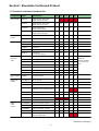
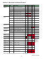
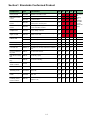
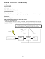
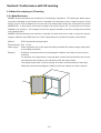
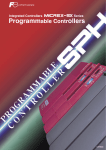
series
USER’S MANUAL
Conformance with Standards
FEH249
Preface
Thank you very much for purchasing the FUJI MICREX-SX Series SPH.
This users' manual describes operational instructions and restrictions on MICREX-SX Series products that conform to
various standards (CE marking, Lloyd's Register of Shipping, etc.)
Please read this manual carefully to correctly use your device.
If your MICREX-SX Series product does not need to conform to CE marking or Lloyd's Register of Shipping, there is no
need to execute the content of this manual. There will be no problem with performance and functionality.
If your MICREX-SX Series product is required to conform to those standards, you must execute the content of this manual.
Note that this manual deals with MICREX-SX Series products of "basic structure," and therefore additional measures
may be necessary depending on the configuration of your system, the structure of the control panel, or the product's work
environment.
<Notes>
1. This manual may not be reproduced in whole or part in any form without prior written approval by the manufacturer.
2. The contents of this manual (including specifications) are subject to change without prior notice.
3. If you find any ambiguous or incorrect descriptions in this manual, please write then down (along with the manual
No. Shown on the cover) and contact FUJI.
Revision
*Manual No. is shown on the cover.
Printed on
*Manual No.
Revision contents
May.2000
FEH249
First edition
Contents
Preface
Revision
Contents
Section1 Standards Conformed Product
1-1 Standards conformed products list ...................................................................................... 1-1
Section2 Conformance with CE marking
2-1 CE marking ............................................................................................................................. 2-1
2-2 Method for adapting to CE marking ..................................................................................... 2-2
2-2-1 Metal Enclosure .............................................................................................................................. 2-2
2-2-2 How to lay the SX bus cable ............................................................................................................ 2-3
2-2-3 Adaptation of individual module ...................................................................................................... 2-4
(1)T-link master / interface module (NP1L-TL1/RT1) ............................................................................. 2-4
(2)OPCN-1 master module ( NP1L-JP1) .................................................................................................. 2-5
(3)FL-net ( OPCN-2 ) module ( NP1L-FL1 ) ............................................................................................. 2-5
(4)Precautions for using the "AS-i" master module ( NP1L-AS1 ) ............................................................ 2-6
(5)DeviceNet master module ( NP1L-DN1 ) ............................................................................................ 2-6
(6)Measures for the positioning modules ................................................................................................. 2-7
Seciton3 Adaptation to UL standard / Lloyd's Resister of Shipping / NK
3-1 Adaptation to UL standard .................................................................................................... 3-1
3-2 Adaptation to Lloyd's Resister of Sipping / NK .................................................................... 3-1
Section4 Installing the PC & Wiring of power supply
4-1 Installing PC units .................................................................................................................. 4-1
4-2 Wiring of power supply ......................................................................................................... 4-2
Section1 Standards Conformed Product
1-1 Standards conformed products list
Component
Type
Specification
CE
UL
cUL
LR
NK
CPU module
NP1PS-74
High-performance CPU module
Program memory:74K steps
yes
no
no
no
no
NP1PS-32
High-performance CPU module
Program memory:32K steps
yes
yes
yes
yes
yes
NP1PH-08
Standard CPU module
Program memory:8K steps
yes
yes
yes
yes
yes
NP1PH-16
Standard CPU module
Program memory:16K steps
yes
yes
yes
yes
yes
Power supply
module
NP1PS-22
100/200V AC
yes
yes
yes
yes
yes
NP1PS-42
24V DC
yes
yes
yes
yes
yes
Base board
NP1BS-06
No.of slots:6
yes
yes
yes
yes
yes
NP1BS-08
No.of slots:8
yes
yes
yes
yes
yes
NP1BS-11
No.of slots:11
yes
yes
yes
yes
yes
NP1BS-13
No.of slots:13
yes
yes
yes
yes
yes
NP1BP-13
No.of slots:13
No.of processor buses:10
yes
yes
yes
yes
yes
NP1C-P3
Cable length:30cm
yes
yes
yes
yes
yes
NP1C-P6
Cable length:60cm
yes
yes
yes
yes
yes
NP1C-P8
Cable length:80cm
yes
yes
yes
yes
yes
NP1C-02
Cable length:2m
yes
yes
yes
yes
yes
NP1C-05
Cable length:5m
yes
yes
yes
yes
yes
NP1C-10
Cable length:10m
yes
yes
yes
yes
yes
NP1C-25
Cable length:25m
yes
yes
yes
yes
yes
SX bus T-branch
uint
NP8B-TB
For SX bus T-branch
yes
yes
yes
yes
yes
Digital input
module
NP1X1606-W
24V DC, 16 points
yes
yes
yes
yes
yes
NP1X3206-W
24V DC, 32 points
yes
yes
yes
yes
yes
NP1X3202-W
5/12V DC, 32 points
yes
yes
yes
yes
yes
NP1X3206-A
24V DC, 32 points
High-speed counter 4 channels 20kHz
yes
yes
yes
no
no
NP1AX6406-W
24V DC, 64 points
yes
yes
yes
yes
yes
NP1X0810
100 to 120V AC, 8 points
yes
yes
yes
yes
yes
NP1X1610
100 to 120V AC, 16 points
no
no
no
yes
yes
NP1X0811
200 to 240V AC, 8 points
yes
yes
yes
yes
yes
NP1Y08T0902
Tr sink 12 to 24V DC, 8 points
yes
yes
yes
yes
yes
NP1Y16T09P6
Tr sink 12 to 24V DC, 16 points
yes
yes
yes
yes
yes
NP1Y32T09P1
Tr sink 12 to 24V DC, 32 points
yes
yes
yes
yes
yes
NP1Y64T09P1
Tr sink 12 to 24V DC, 64 points
yes
yes
yes
yes
yes
NPY32T09P1-A
Tr sink 24V DC, 32 points
Pulse train output function
yes
yes
yes
no
no
SX bus
expansion
cable
Digital
output
module
To adapt to CE
marking, the
measures described
in 2-2-2 need to be
taken.
( Continued on next page )
1-1
Section1 Standards Conformed Product
Component
Type
Specification
CE UL cUL LR
NK
Digital output
module
NP1Y08U0902
Tr source 12 to 24V DC, 8 points
yes
yes
yes
yes
yes
NP1Y16U09P6
Tr source 12 to 24V DC, 16 points
yes
yes
yes
yes
yes
NP1Y32U09P1
Tr source 12 to 24V DC, 32 points
yes
yes
yes
yes
yes
NP1Y64U09P1
Tr source 12 to 24V DC, 64 points
yes
yes
yes
yes
yes
NP1Y06S
Triac 100 to 200V AC, 6 points
yes
yes
yes
yes
yes
NP1Y08S
Triac 100 to 200V AC, 8 points
no
no
no
yes
yes
NP1Y08R-04
Ry 110V DC,240V AC, 8 points
yes
yes
yes
yes
yes
NP1Y16R-08
Ry 110V DC,240V AC, 16 points
no
no
no
yes
yes
NP1W1606T
input : sourse type24V DC, 8 points
output : Tr sink12 to 24V DC, 8 points
yes
yes
yes
yes
yes
NP1W3206T
input : source type24V DC, 16 points
output : Tr sink12 to 24V DC, 16 points
yes
yes
yes
yes
yes
NP1W1606U
input : sink type24V DC, 8 points
output : Tr source12 to 24V DC, 8 points
yes
yes
yes
yes
yes
NP1W3206U
input : sink type24V DC, 16 points
output : Tr source12 to 24V DC, 16 points
yes
yes
yes
yes
yes
NP1AXH4-MR
4 channels, Resolution : 14bits
yes
yes
yes
yes
yes
NP1AX04-MR
4 channels, Resolution : 10bits
yes
yes
yes
yes
yes
NP1AX08-MR
8 channels, Resolution : 10bits
yes
yes
yes
no
no
Multi-range Analog
output module
NP1AYH2-MR
2 channels, Resolution : 10bits
yes
yes
yes
yes
yes
NP1AY02-MR
2 channels, Resolution : 10bits
yes
yes
yes
yes
yes
General purpose
communication
module
NP1L-RS1
RS-232C : 1 channel, RS-485 : 1 channel
yes
yes
yes
yes
yes
NP1L-RS2
RS-232C : 1 channel
yes
yes
yes
yes
yes
NP1L-RS4
RS-485 : 1 channel
yes
yes
yes
yes
yes
FL-net ( OPCN-2 )
module
NP1L-FL1
FL-net (OPCN-2 ) : 1 channel
yes
no
no
no
no
P-link module
NP1L-PL1
P-link : 1channel
no
yes
yes
no
no
PE-link module
NP1L-PE1
PE-link : 1 channel
no
yes
yes
no
no
OPCN-1 master
module
NP1L-JP1
OPCN-1 : 1 channel
yes
yes
yes
yes
yes
OPCN-1 interface
module
NP1L-RJ1
interface module to expansion OPCN-1
yes
yes
yes
yes
yes
DeviceNet master
module
NP1L-DN1
DeviceNet : 1 channel
yes
no
no
no
no
AS-i master module
NP1L-AS1
AS-i master : 1 channel
yes
no
no
no
no
T-link master
module
NP1L-TL1
T-link master : 1 channel
yes
yes
yes
yes
yes
T-link interface
module
NP1L-RT1
interface module to expansion T-link
yes
yes
yes
yes
yes
PC card interface
module
NP1F-PC2
General purpose PC card : 1 channel
memory card : 1 channel
yes
no
no
no
no
Memory card
interface module
NP1F-MM1
SRAM memory card : 1 channel
yes
no
no
no
no
Digital input/output
module
Multi-range Analog
input module
( Note )
To adapt to CE
marking, the
measures
described in 22-3 need to be
taken.
( Note )To adapt to CE marking, the measures described in 2-2-3 need to be taken.
( Continued on next page )
1-2
Section1 Standards Conformed Product
Component
Type
Specification
CE
UL
Dummy module
NP1F-DMY
substitute for the failed module
yes
no
no
no
no
High-speed counter
module
NP1F-HC2
2 channels 500kHz
yes
no
no
no
no
NP1F-HC8
8 channels 50kHz
yes
no
no
no
no
Pulse train output
module
NP1F-HP2
Pulse train command, 2 channels 250kHz
Forward pulse + reverse pulse
yes
no
no
no
no
Pulse train multiple
module
NP1F-MP2
Positioning control multiple module
2 axes, Pulse train command
yes
no
no
no
no
Analog
multiplemodule
NP1F-MA2
Positioning control multiple module
2 axes, Analog command
yes
no
no
no
no
Signal converter
NP2F-LEV
Convert signal level, From open collector signal to
RS-485 or vice versa
yes
no
no
no
no
NP4H-CNV
Personal computer cable for loader with converter
yes
yes
yes
yes
yes
NP4H-CA2
Personal computer cable for loader
yes
yes
yes
yes
yes
Simulative-input swich NP8X-SW
16 points
yes
yes
yes
yes
yes
Data backup battery
NP8P-BT
Lithium primary battery
yes
yes
yes
yes
yes
User ROM card
NP8PMF-16
User ROM card 16k steps Dedicated to standard
CPU
yes
yes
yes
yes
yes
CPU mode selection
key swich
NP8P-KY
For CPU mode selection
yes
yes
yes
yes
yes
Base board mounting
stud
NP8P-ST
For DIN rail (in pairs)
yes
yes
yes
yes
yes
SX bus terminating
plug
NP8P-BP
For SX bus terminating
yes
yes
yes
yes
yes
T-link connector,
JPCN-1 connector
FCT120T
yes
yes
yes
yes
yes
P/PE-link connector
FTC120P
yes
yes
yes
yes
yes
T-link/JPCN-1
terminating resistor
FRT120A100
100Ω/1W
yes
yes
yes
yes
yes
P/PE terminating
resister
FRT220A75
75Ω/1W
yes
yes
yes
yes
yes
I/O connector,
Positioning control
module connector
NP8V-CN
Soldered socket type,connector cover
(Fujitsu Co.,Ltd.)
yes
yes
yes
yes
yes
D300win cable
1-3
cUL LR NK
To adapt to
CE
marking,
the
measures
described
in 2-2-3
need to be
taken.
Section2 Conformance with CE marking
2-1 CE marking
<Product standard>
IEC 61131-2
EMI = CISPR11, Gr. 1, Class A
EMS = IEC 61000-4-2 to -6, -8 and -12
<Classification of product>
Enclosed type equipment, which is defined as follows:
"To prevent accidents due to a charged or operating part coming into contact with the human body, the
product should be installed in a metal enclosure when used."
<Safety level>
Overvoltage Category II
<EMC classification when installing PLC defined in IEC 61131-2>
Zone B, which is defined as follows:
"An environment where power from an external power supply, which supplies power to the factory (the building in which the device is installed), is used after doubly protecting against surge voltage with an insulating
transformer or the like.
An environment that is doubly protected against surge voltage, but in
which the superimposition of industrial environment noise may occur.
Factory
Lightning
Zone C
3-phase power supply
Primary
protection
2-1
Zone B
Secondary
protection
PLC
MICREX-SX
Section2 Conformance with CE marking
2-2 Method for adapting to CE marking
2-2-1 Metal Enclosure
MICREX-SX Series products are classified as "enclosed type" equipment. "Enclosed type" means equipment that is designed on the condition that it is installed in an enclosure such as a metal enclosure, so that
electric shock or other accidents do not occur due to the human body coming into contact with the product
(MICREX-SX). In other words, there may be danger of an electric shock, etc., if the product is not accommodated in an enclosure. (For example, a steel wire may be inserted in one of the cooling slots provided
on the product body.)
MICREX-SX Series products also need to be installed in a metal enclosure in order to control the electromagnetic radiation noise (EMI) they emit. Basic specifications for the metal enclosure are as follows.
Material
: SPCC (high-tensile-strength steel)
Plate thickness : Min. 1.6 mm
Power supply : Power supplied to the control panel should be protected from external surge voltage with
an insulating transformer.
Remarks
: Should be structured so that an electromagnetic radiation noise does not leak from the
enclosure.
For example, in the figure below, a box-type door is used, and the enclosure has an eavelike protrusion that overlaps on the side faces of the door when closed.
The important point here is that the overlap of the door and the enclosure's main body
effectively prevents electromagnetic radiation noise from leaking out of the enclosure.
Door
扉
Eave
ひさし
2-2
Section2 Conformance with CE marking
2-2-2 How to lay the SX bus cable
<Mounting the ferrite core>
A high-speed electric signal flows through the SX bus cable. Therefore, high-frequency noise is emitted
from the SX bus cable, making it impossible for the product to conform to the EMC directive concerning CE
marking.
To solve this problem, a ferrite core is mounted at the base of the SX bus cable.
Mount the ferrite core according to the figure below.
Commendable ferrite core
: ZCAT 3035-1330 from TDK
<How to affix the cable to the metal enclosure>
When affixing the SX bus cable to the metal enclosure, be sure to secure a 1-cm or wider gap so that the
SX bus cable does not come into contact with the metal plate.
On the one hand, the metal enclosure provides an effective shield fromelectromagnetic radiation noise; on
the other hand, it becomes an effective antenna that electromagnetic radiation noise if a cable as a noise
source is nearby or comes into actual contact with it. Not only the SX bus cable, but also other high-speed
signal transmission cables need to be kept away from the metal walls of the enclosure.
2-3
Section2 Conformance with CE marking
2-2-3 Adaptation of individual module
(1) T-link master/interface module (NP1L-TL1 / RT1)
When a T-link master module is used, it is necessary to mount the ferrite core at the base of the communication cable as well as affix insulating sheet. When the T-link interface module is used, it is necessary to
mount the ferrite core at the base of the communication cable.
1) Mount the ferrite core at the root of the communication cable.
* Ferrite core mounting may be unnecessary if all of
the communication cable is laid only inside the
metal enclosure, or even when it is laid outside the
metal enclosure, if it is laid in EMI shielding tube or
metal tube so that no noise leaks out.
Commendable ferrite core
: ZCAT 3035-1330 from TDK
Note:
If vibration or shock is applied to the product, a
strong force due to the weight of the ferrite core
may act on the cable to damage it. Be sure to affix the cable to a firm object such as a duct so
that the cable does not swing under vibration.
2) Affix the static electricity preventive insulating sheet to the station number-setting switch
When a station number needs to be changed while the module is operating, it is once necessary to remove
the insulating sheet for this work. For this operation, the operator must remove static electricity accumulated on his body by means of a static elimination band or the like before touching the station number-setting switch. This is necessary only for the T-link master module (NP1L-TL1), and not necessary for the Tlink interface module (NP1L-RT1).
Affix the insulating sheet supplied with the product on the station numbersetting switch.
Note:
For the purpose of explanation, a colored sheet is used in the
photo at left. The actual insulating sheet supplied with the product is transparent.
2-4
Section2 Conformance with CE marking
(2)OPCN-1 master module (NP1L-JP1)
When a OPCN-1 master module is used, it is necessary to the stick-insulating sheet.
1) Affix the static electricity preventive insulating sheet to the station number-setting switch
When a station number needs to be changed while the module is operating, it is once necessary to remove the insulating sheet for this work. For this operation, the operator must
remove static electricity accumulated on his body by means of a static elimination band or
the like before touching the station number-setting switch.
Affix the insulating sheet supplied with the product on the station numbersetting switch.
Note:
For the purpose of explanation, a colored sheet is used in the photo
at left. The actual insulating sheet supplied with the product is
transparent.
(3) FL-net ( OPCN-2 ) module (NP1L-FL1)
When the "FL-net ( OPCN-2 )" module is used, in order to control electromagnetic radiation noise emitted
from the communication cable, a ferrite core needs to be mounted at the base of the cable.
1) Mount the ferrite core at the base of the communication cable.
Commendable ferrite core
: ZCAT 3035-1330 from TDK
Note:
If vibration or shock is applied to the product, a
strong force due to the weight of the ferrite core
may act on the cable to damage it. Be sure to affix the cable to a firm object such as a duct so
that the cable does not swing under vibration.
* Ferrite core mounting may be unnecessary if all of the communication cable is laid only inside the metal
enclosure, or even when it is laid outside the metal enclosure, if it is laid in EMI shielding tube or metal
tube so that no noise leaks out.
2-5
Section2 Conformance with CE marking
(4) Precautions for using the "AS-i" master module (NP1L-AS1)
When the "AS-i" module is used, the operator who works on the terminal block for connecting the signal
cable must discharge static electricity accumulated on his body by means of a static elimination band or
the like before touching the terminal block so that static discharge to the terminal block does not occur.
Static discharge to the terminal block does not occur.
(5) DeviceNet master module (NP1L-DN1)
When the "DeviceNet" master module is used, be sure to take the following measure.
1) Mount the ferrite core at the base of the communication cable.
Commendable ferrite core
: ZCAT 3035-1330 from TDK
Note:
If vibration or shock is applied to the product, a
strong force due to the weight of the ferrite core
may act on the cable to damage it. Be sure to affix the cable to a firm object such as a duct so
that the cable does not swing under vibration.
* Ferrite core mounting may be unnecessary if all of the communication cable is laid only inside the metal
enclosure, or even when it is laid outside the metal enclosure, if it is laid in EMI shielding tube or metal
tube so that no noise leaks out.
2-6
Section2 Conformance with CE marking
2) Affix the static electricity-preventive insulating sheet on the station number-setting switch.
Take measures to prevent static discharge to the terminal block for the signal cable.
Affix the static electricity preventive insulating sheet to the station number-setting switch.
When a station number needs to be changed while the module is operating, it is once necessary to remove
the insulating sheet for this work. For this operation, the operator must remove static electricity accumulated on his body by means of a static elimination band or the like before touching the station number-setting switch.
Affix the insulating sheet supplied with the product on the station numbersetting switch.
Note:
For the purpose of explanation, a colored sheet is used in the photo
at left. The actual insulating sheet supplied with the product is
transparent.
Static discharge to the terminal block does not occur.
(6) Measures for the positioning modules
When one of the following modules is used, a ferrite core needs to be mounted at the base of all the cables
connected to the module as well as the power and FG cables leading to the power module mounted on the
baseboard on which the positioning module is also mounted.
NP1F-HC2/NP1F-HC8
NP1F-HP2/NP1F-MP2/NP1F-MA2
Commendable ferrite core
: ZCAT 3035-1330 from TDK
Note:
If vibration or shock is applied to the product, a
strong force due to the weight of the ferrite core
may act on the cable to damage it. Be sure to affix the cable to a firm object such as a duct so
that the cable does not swing under vibration.
Wire to a power supply and grounding wire
2-7
Section3
Adaptation to UL standard / Lloyd's Register of Shipping / NK
3-1 Adaptation to UL standard
No restriction
3-2 Adaptation to Lloyd's Register of Shipping / NK
Ship standards such as Lloyd's Register of Shipping and NK (Nippon Kaiji Kyokai) are almost the same as that for CE
marking, except that vibration- related rules are more severe in the former than in the latter.
Therefore, when a MICREX-SX Series product is used for marine equipment, tightly wind a strong nylon band around the
entire PLC so that the modules come in close contact with each other, as shown in the figure below.
A guideline for checking the propriety of the contact is whether or not a name card can be inserted in between the modules.
Fix by tightly winding a nylon band
around the SX.
After fixing with a nylon band, check to see that a
name card cannot be inserted in the gap between the modules.
3-1
Section4 Installing the PC & Wiring of power supply
4-1 Installing PC uints
80mm or more
Unite
Unite
MICREXSX
110mm or more
Other
device
Remote I/O
10mm or more
2)
2)
3) Heat generating
device
Incorrect
1)
110mm
or more
50mm or more
Duct
50mm or more
MICREX-
1)
50mm or more
50mm or more
1)
Remote I/O
Unite
Remote I/O
1) 110mm or more
10mm or more
SX
4)
Highvoltage
device
5)
50mm or more
Duct
Incorrect
Incorrect
Mounting angle
0°
Incorrect
90°
Keep an open space as follows:
1) Keep an open space of 110mm (vertical) or 10mm (horizontal) between the PC unites, between remote I/O modules the
PC unit and remote I/O module.
Note:When the base board is mounted on a DIN rail, keep an open space of 80mm in consideration of mounting bracket
dimensions and the workability.
2) Keep an open space of 50mm between the PC unit and other device and between the PC unit and the wall to obtain
sufficient ventilation.
3) Avoid installing heat generating devices (heaters, transformers, or resistors) underneath the PC unit.
4) Shield or separate the PC unit as far from high voltage device, high-voltage cables, or power equipment as possible.
Avoid installing PC I/O cables unit and high-voltage or power equipment cables in parallel.
5) Install the PC unit perpendicular to the panel floor.
6) The PC must be installed in a vertical position. Do not install the PC in other position.
4-1
Section4 Installing the PC & Wiring of power supply
4-2 Wiring of power supply
Keep the distance between the insulating transformer
(or the noise filter) and the power supply module as
AC power supply
Breaker
short as possible, and the cable must be twisted
densely.
M4 screw
AC power
supply
1)
Insulating transformer,
Noise filter
100V AC:85 to132V AC
200V AC:170V to 264V AC
Do not bundle up and di not close
(Note) Be sure to use crimp terminals.
( Tightening torque:1.2N·m)
DC power supply
Breaker
3)
2)
Grounding
ground resisstance of 100Ω
Votage selection
or less
Short:100V AC
Open:200V AC
Keep the distance between the DC power suplly
and the the power supply module as short as
possible, and the cable must be twisted densely.
1)
DC pwer
supply
M4 screw
24V DC:22.8-26.4V DC
3)
Grounding
1) Wiring of power supply
ground resisstance of 100Ω
or less
For AC power supply
Wire to a 100 to 120V AC or 200 to 240V AC power supply.
The thickness of the wire must be 2mm2, and the wire must ne twisted densely.
For DC power supply
Wire to a 24V DC power supply (22.8-26.4V DC).
The thickness of the wire must be 2mm2, and the wire must ne twisted densely.
[Tips]
The tolerance range of MICREX-SX AC power supply is 85 to 132V AC for 100V AC, and 170 to 264V AC for 200V AC. But
the voltage is recommended to be as near the rated voltage (100 to 110V AC, 200 to 220V AC) as possible.
In the case of the lower voltage, a small voltage drop will cause a power failure. In the case of the higher voltage, the heating value of the power supply module increases and it reduces the life of the module. If power supply voltage fluctuation
exceeds the specified range, connect a voltage stabilizer to the power supply.
For noise reduction of the power supply, an insulating transformer or a noise filter is effective between the breaker and the
power supply module. Take care of the following points:
• Do not bundle up or do not close the insulating transformer or the noise filter.
• Keep the distance between the insulating transformer (or the noise filter) and the power supply module as short as
possible, and the cable must be twisted densely.
4-2
Section4 Installing the PC & Wiring of power supply
2) Voltage selection (for only AC power supply)
100V AC : Short (using a jumper cable)
200V AC : Open
3) Grounding
• Connect the FG terminal to the integrated ground section of each control panel (FG bus, FG integrated terminal block, or
stud) in branch-type configuration. The thickness of the ground wire must be 2mm2. Allocate the grounding point as near
the module as possible, and keep the ground wire as short as possible.
• The integrated ground section of each control panel must be connected to the integrated ground board, which is installed
according to the distribution of devices in a branch-type configuration. The thickness of the ground wire must be 5.5mm2
or more.
• Separate the ground wire as far from the lines of high-voltage circuits and main circuit as possible. In addition, keep the
distance at which they run in parallel as short as possible.
• For grounding, use an exclusive ground pole and wire which are separated from the ground system of other power cir
cuits.
• The grounding should be exclusive. The grounding resistance is 100Ω or less. Separate the ground pole 10m or more
from that of other power circuit.
• When installing in a place affected by frequent lighting surges, all the CPU modules and input/output modules should be
electrically insulated from the control panel. Also, modules and units should be earthed to ground individually.
PC
Other
device
PC
Other
device
PC
Other
device
Grounding
resistance
Grounding
resistance
100Ωor less
100Ωor less
Exclusive grounding....Best
Common grounding....Good
Common grounding ....Not acceptable
Warning
Do not open the FG terminal with LG-FG short circuited. (It must be grounded, otherwise it might cause electric
shock.)
4-3
Section4 Installing the PC & Wiring of power supply
<Grounding example>
Power supply
SX bus
Power supply
Control panel
LG
FG
Operator panel
T-link master
LG
FG
Remote
I/O
FG
POD
2mm2
FG bus
Integrated ground section
FG bus
5.5mm2 or more
Integrated ground section
Integrated ground board
Grounding
4-4
Gate City Ohsaki, East Tower,
11-2, Osaki 1-chome, Shinagawa-ku, Tokyo 141-0032, Japan
E-mail: [email protected]
URL: http://www.fujielectric.com/
Materials covered in this document are subject to revision due to the modification of the product.
Issued as FE consolidated edition, June 2011