1
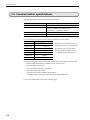
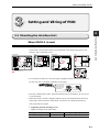
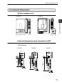
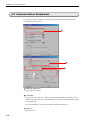
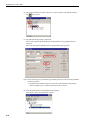
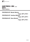
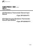
FUJI UG SERIES PROGRAMMABLE OPERATION DISPLAY
USER'S MANUAL
<UG SERIES SX-BUS Communications>
TYPES: UG03I-S
UG02I-S
FEH357a
Preface
Thank you very much for purchasing the Fuji UG Series Programmable Operation Display.
This manual describes how to use the SX-bus interface type.
This manual will help you understand the outline information and to master it efficiently by
giving examples in each chapter.
In addition to this manual, the following manuals on the UG Series are available. Please
ask your nearest dealer for the appropriate manuals and read them too.
Name
Manual No.
Contents
UG Series User’s Manual
<Operation>
FEH375
Describes how to operate the screen editor
(UG00S-CW) for the UG Series.
UG Series User’s Manual
<Function>
FEH376
Describes the functions of the UG Series.
UG30 Series User’s Manual
<Hardware>
FEH377
Describes the hardware of the 530/430/330
Series.
UG20 Series User’s Manual
<Hardware>
FEH352
Describes the hardware of the 520/420/320/
220/221 Series.
UG Series User’s Manual
FEH363
Describes the function to link variable
names between UG editor and D300win.
<Variable Name Cooperation Function>
Notes
(1) No part of this manual may be reproduced in any form without the prior permission of the
publisher.
(2) The contents of this manual, including the specifications, are subject to change without notice
for the purposes of improvement.
(3) This manual was prepared with the utmost care. However, if you find any ambiguity, errors,
etc., please contact any of our sales offices that are listed at the end of this manual. When you
do so, be sure to quote the manual number given on the cover of this manual.
Record of Revisions
The manual number is shown at the bottom right of the front cover.
Printing Date
Reference No.
Revised Contents
August, 2001
FEH357
1st Edition printed
January, 2003
FEH357a
2nd Edition printed
• Explanations on UG30 Series added
• Some explanations reviewed added
Contents
Preface
Record of Revisions
Contents
1. General ............................................................................. 1-1
2. Specifications ................................................................... 2-1
2.1 Applicable Models .............................................................................2-1
Applicable PLCs .............................................................................................. 2-1
Applicable PODs .............................................................................................. 2-1
2.2 Communication Specifications .......................................................... 2-2
2.3 Available Areas of PLC Internal Memory ............................................2-3
3. Setting & Wiring of POD .................................................... 3-1
3.1 Mounting the Interface Unit ..............................................................3-1
When UG03I-S is used ..................................................................................... 3-1
When UG02I-S is used ..................................................................................... 3-3
3.2 Cable Connection and Station Number Setting .................................. 3-4
3.3 External Dimensions........... ..............................................................3-5
SX bus interface unit ...................................................................................... 3-5
External dimensionswhen mounted on POD .................................................... 3-5
4. Screen Data Editing .......................................................... 4-1
4.1 Select PLC Type ................................................................................4-1
4.2 Communication Parameters ..............................................................4-2
5. Registration on PLC Side(Setting with D300win) ............... 5-1
5.1 Registration of POD ..........................................................................5-1
5.2 Registration of System Fall-Soft startup Operation ........................... 5-3
General
1
General
General
• This type of SX Bus I/F unit enables high-speed data transmission with MICREX-SX
Series PLCs.
• The POD updates the display when there is a change in the read data (POD
PLC).
The read data is the content of the PLC addresses assigned to the display elements,
such as the current status of the lamps and counters, which are created on the
individual screen the POD displays.
When a POD switch or counter setting element is operated, the POD sends a write
command to the PLC and writes the output data in the PLC internal memory which
corresponds to the operation data.
These operations are automatically performed by POD, and therefore it is unnecessary
to create a communications program on the PLC side.
Write command (example): Write the set value of timer 1
POD
Output processing
Input processing
• Data display
• Switch
• Data display
(object of input)
• Lamp
Read command (example): Monitor all the data displayed on the screen
1-1
General
1-2
Specifications
Specifications
2
Applicable Models
2.1 Applicable Models
Applicable PLCs
The following PLC models are applicable:
NP1PS-xx :SPH300 Series
NP1PH-xx :SPH200 Series
* No communication module is necessary on the PLC side.
Applicable PODs
Be sure to use the following type of communication unit according to the type of POD
you use.
POD type
UGx30H-x
Type of communication unit
UG520H-x
UG420H-x
UG03I-S
UG320H-x
UG221H-x
UG220H-x
UG02I-S
* UG420H-Ex (EL display type) and UG320HD (handy type) cannnot be used.
2-1
Specifications
2.2 Communication specifications
The table below shows the communication specifications:
Item
Transmission line
Specification
Dedicated cable *1 Total length 25 m
Connectable sets
Number of PODs connectable in same
configuration via SX bus: 8 sets *2
Transmission rate
PLC connecting range
25Mbps
CPU in same configuration *3
*1 For connection, be sure to use the following SX bus extension cable:
Type
NP1C-P3
Cable length (Unit: mm)
300
NP1C-P6
NP1C-P8
600
800
NP1C-02
NP1C-05
2,000
5,000
NP1C-10
NP1C-25
10,000
25,000
When you use UG03I-S, be sure to
mount the ferrite core included with
the product on the SX bus cable.
For the mounting method, refer to
“3.1 Mounting the Interface Unit”.
*2 Though maximum 8 sets of POD can be connected in one configuration, the total
when including the following modules must be 16 sets or less.
• P-link module (NP1L-PL1)
• PC card interface module (NP1F-PC2)
• PE-link module (NP1L-PE1)
• Memory card interface module (NP1F-MM1)
• General-purpose communication module (NP1L-RS1/RS2/RS4)
*3 For more information, refer to the following page.
2-2
Specifications
2.3 Available Areas of PLC Internal Memory
The table below shows the communication specifications:
2
Memory range
Input memory
(I)
Output memory
(Q)
Format Unit
TYPE
NP1PH-08
%IX■.0.0~
%IX■.511.15
%IX■.0.0~
%IX■.511.15
%IX■.0.0~
%IX■.511.15
bit
%IW
word
%IW■.0~
%IW■.511
%IW■.0~
%IW■.511
%IW■.0~
%IW■.511
%QX
bit
%QX■.0.0~
%QX■.511.15
%QX■.0.0~
%QX■.511.15
%QX■.0.0~
%QX■.511.15
%QW
word
%QW■.0~
%QW■.511
%QW■.0~
%QW■.511
%QW■.0~
%QW■.511
—
—
bit
2
%MW word
.1
System memory
(SM)
NP1PH-16
%IX
Standard memory %MX
(M)
.1
Retain memory
(RM)
NP1PS-32
%MX .1.0.0~
%MX .1.0.0~
%MX .1.0.0~
%MX 1.32767.15 %MX 1.31743.15 %MX 1.15359.15
%MW .1.0~
%MW 1.32767
%MW .1.0~
%MW 1.31743
%MW .1.0~
%MW 1.15359
%MX .3.0.0~
%MX 3.30719.15
%MX .3.0.0~
%MX 3.31743
%MX .3.0.0~
%MX 3.15359
%MW word
.3
%MW .3.0.0~
%MW .3.30719
%MW .3.0.0~
%MW .3.31743
%MW .3.0.0~
%MW .3.15359
%MX
.10
%MX .10.0.0~
%MX .10.511.15
%MX .10.0.0~
%MX .10.511.15
%MX .10.0.0~
%MX .10.511.15
%MW .10.0~
%MW 10.511
%MW .10.0~
%MW 10.511
%MW .10.0~
%MW 10.511
%MX
.3
bit
4
bit
8
%MW word
.10
Available Areas of PLC Internal Memory
Memory
• Memory area is specified basically by variable name linkage. For more information
about variable name linkage, refer to “UG Series Manual <Variable Name
Cooperation>” (FEH363).
• ■ in the above table is SX station No. (1 to 238).
•
in the above table is CPU No. (0 to 7).
• Figures for the memory range in the above table are when individual area is set to the
maximum. Actual range depends on “CPU memory size” defined on the PLC side.
• TYPE is used when memory is indirectly specified using macros from the POD
editor.
• When memory is indirectly specified using macros from the POD editor, be sure to
define CPU No. in the extension code.
• Input and output memories (%I, Q) cannot be indirectly specified using macros from
the POD editor.
2-3
Setting and Wiring of POD
Setting and Wiring of POD
3
Mounting the Interface Unit
3.1 Mounting the Interface Unit
When UG03I-S is used
• Remove the dust preventive seal from the I/F unit connector (UG30 Series : CN5,
UG20 Series : See the figure below) on the backside of the POD, mount the I/F unit
and fix it with 3 mounting screws.
UG330
UG530/UG430
UG320
UG520/UG420
CN6
LAN
CN6
(+)
DC 24V
(-)
L
CN5
100240VAC
N
MEMORY
MJ2
NC
MJ1
MEMORY
CN5
CN1
CF
CF
24VDC
- +
PRINTER
MJ1
CN1
MJ2
LAN
CN1
MJ1
MJ2
CN1
CN2
100-240VAC
L
N
PRINTER
MJ2
MJ1
UG221
CN2
+
24VDC
-
Connector for I/F unit
MJ1
CN2
CN1
• For UG30 and UG320/221 , insert the spacer (supplied with the unit) before mounting
the unit. Be sure to check the orientation of the spacer.
Insert a spacer with
the burr side upward
and with the round
side (R) inside.
Burr
R
Spacer
Rear side of POD
• Wire the communication cable. When the POD becomes a termination, be sure to use
a loop-back plug.
• Mount the ferrite core that is supplied with the unit on the communication cable to be
connected to the IN connector of the POD. The ferrite core should be mounted as
near to the POD as possible.
*
Tightening the unit mounting screws
Tighten according to the table below:
Type of screw
Screw size
Tightening torque (N.m)
Unit mounting screw
M3
0.3 to 0.5
3-1
Setting and Wiring of POD
• Notes on the CE specification
UG03I-S can be used as CE-approved IF unit ; however, note the following restrictions.
Available models
UGx30H-xx4
UG520H-xC4ZE
UG520H-xC4MZE
UG420H-xC4ZE
UG420H-xC4MZE UG320H-SC4ZE
UG221H-xx *
* UG221 of the following and later hardware versions are supported.
UG221H-TC4
UG221H-LC
-> Version 1
-> Version 1
UG221H-SC4
UG221H-TC4D
-> Version 2
-> Version 4
UG221H-SC4D -> Version 6
UG221H-LC4D -> Version 5
The hardware version of the unit is indicated in the third digit from the extreme left of
the serial number shown on the backside of the unit.
Mounting procedure
When mounting UG03I-S on UG221 for CE specification, connect the FG terminal of
UG221 to the FG terminal of UG03I-S using the FG cable supplied with the unit.
FG cable
MJ2
CN2
MJ1
CN1
FG of UG03I-S
Notes on peripheral equipment
If both UG03I-S and UG00P-MR ( memory card recorder ) are used at the same time,
it is not possible to make UG03I-S CE-approved.
3-2
Setting and Wiring of POD
When UG02I-S is used
• Route the insulated cable through the notch.
I/F unit
3
Mounting the Interface Unit
Notch
• After removing the dust preventive seal which is stuck on the rear of the POD, mount
the I/F unit at the position shown in the figure below and fix it with the 4 mounting
screws (M3 8) supplied with the unit.
I/F unit
Mounting screws*
(4 positions)
DC24V
(+)
(-)
CN1
CN2
MJ2
MJ1
POD
• Connect the insulated cable with the ground terminal on the POD.
• Wire the communication cable. When the POD becomes a termination, be sure to use
a loop-back plug.
*
Tightening the unit mounting screws
Tighten according to the table below:
Type of screw
Screw size
Tightening torque (N.m)
Unit mounting screw
M3
0.3 to 0.5
3-3
Setting and Wiring of POD
3.2 Cable Connection and Station Number Setting
• UG03I-S
• UG02I-S
Station No. setting switch
012
3456
3456
EF
BCD
F0 1 2
BCD
E
78 9A
2
78 9A
SW1 SW2
IN
SW1 SW2
IN
1
OUT
OUT
SX bus connector
1
SX bus connector
1
SX bus connector
• Be sure to connect the cable that comes from OUT connector to the IN connector
of the mating device.
Communication is impossible if this cable is connected between OUT connectors
or between IN connectors.
• For connection, be sure to use the dedicated SX bus extension cable.
(For more information about the SX bus extension cable, refer to “2-2
Communication Specifications”.)
2
Station number setting switch
• This switch is used to set local station number on the SX bus. SW1 sets the highorder digit of station number while SW2, the low-order digit.
Turn the rotary switches with a screwdriver to set a station number in the range
from 00 to FF (hexadecimal).
The station number that is set on the POD side (with the above
setting switches) must be the same as the station number that is set
on the PLC side (using the [System_Definition] function of
D300win). Communication is not normally performed if different
station number is set.
For more information about the registration with D300win, refer to
“5.1 Registration of POD”.
Precautions for setting station No
On the POD side, station number is set by “hexadecimal” number in
the range from 00 to FF using the setting switch; on the PLC side,
station number is set by “decimal” number in the range from 0 to
255 using D300win.
Example:
When station number is set to 10 (h) (by setting SW1 to “1” and
SW2 to “0”) on the POD side, “SX bus station number (N)” that is
set by D300win on the PLC side must be “16”.
3-4
Setting and Wiring of POD
3.3 External Dimensions
SX bus interface unit
. UG02I-S
. UG03I-S
102.5
28.5
3
167.4
150.5
IN
External Dimensions
SW1 SW2
IN
OUT
SW1 SW2
OUT
13.6
14.9
37.8
25
98
External dimensions when mounted on POD
.
UG30 Series
.UG330H
.UG430H
93
87.1
93
72
66.1
21
21
72
245.2
215.2
165
21
.UG530H
6.6
8
8
3-5
Setting and Wiring of POD
.
UG20 Series
UG520
UG420
288
312
8
126
110
240
270
245.2
114.5
334
310
UG320
UG221
25
I/F unit
UG220
28.5
173.6
130.8
138.8
5
50
I/F unit
130.8
165
182.5
230
182.5
138.8
85
175
85
6
6
53.3
66.1
I/F unit
25
173.6
220
3-6
215.2
11.5
141.5
16
16
92.3
I/F unit
95.8
I/F unit
Setting for Creating Screens
Screen Data Editing
This section describes the items to be set for SX Bus communications when creating
screens with the editor (personal computer).
For more information about the way to set or use UG00S-CW , refer to user’s manual
[Function] (FEH376) .
4
Setting PLC Type
To create screen data for SX bus interface, use UG00S-CW , or Ver.
2.10 or higher UG00S-3WE ( for Windows ) .
With UG00S-3WE of Ver. 2.10, UG00S-3N (for 98DOS) or UG00S3D (for DOS/V), no definition can be made for SX bus interface.
4.1 Select PLC Type
Click [System Setting ], then click [PLC Type] . Select [FUJI ; MICREX-SX ] on the
[Select PLC Type] dialog.
4-1
Setting for Creating Screens
4.2 Communication Parameters
For setting of [Comm. Parameter...] under [System Setting], differences from other
communication methods are:
1
2
3
1
Baud rate/signal level
These items are omitted.
2
Connection
Needs not be set in this case. When 1:n connection (multiple sets of POD) is used,
definition is made on the PLC side (D300win) as well as at individual SX bus station
on the POD side.
For more information, refer to user’s manual [Function] (FEH376).
3
Parity, etc.
Need not be set.
4-2
Registration on PLC Side
5
Registration on PLC Side
(Setting with D300win)
This section describes how to set the PLC side program loader (D300win) in order to
register the POD system that performs communication via SX bus interface. For other
information about D300win, including operation method, refer to user’s manual
[D300win <Reference> ] (FEH251).
Be sure to use Ver. 1.2.0.0 or newer D300win.
5
5.1 Registration of POD
Registration of POD
The procedure to register the system configuration in which one set of POD is
connected to SPH300 Series via SX bus interface is described below.
Power
supply
POD: SX bus station No. 1
(1) Double-click the [System_Definition] icon in the D300win project tree.
5-1
Registration on PLC Side
(2) The system definition window is opened. On this window, click [Base] and then
the
[Insert] icon.
(3) The [Module Insert] dialog is displayed.
Turn ON the optional [Individual type module] button in the [Module attribute
type] box.
Then, turn the optional [POD] button in the [Module group type] box.
Note: In the following case, [Individual type module] cannot be selected in the [Module
attribute type] box:
→ [Individual type module] cannot be selected on the [Module Insert] dialog
unless the [Base] icon is clicked (selected) in above step (2).
(4) Click the [OK] button on the [Module Insert] dialog.
You return to the system definition window.
5-2
Registration on PLC Side
The SX bus station number that is registered
using D300win must be the same as the SX
bus station number that is indicated on the
rear of the SX bus interface unit. If a
different number is set, communication
cannot normally be performed.
SX bus station number set by D300win
(Using the [Property] dialog of the module)
5.2 Registration of System Fail-Soft Startup Operation
POD is treated as a module with station number setting switch. Therefore, “System
Fail-Soft Startup Operation Definition” is useful.
5
(1) On the system definition window, click [System Property] and then the
Registration of System Fail-Soft Startup Operation
[Property] button.
(2) The [System Property] dialog is displayed.
Double-click [Fail-soft operations setting] and select a desired fail-soft startup
operation mode.
For more information about fail-soft startup operation mode, refer to user’s manual
<Instruction>, MICREX-SX Series SPH (FEH200).
5-3
Fuji Electric Co., Ltd.
ED & C.Drive Systems Company
Gate City Ohsaki, East Tower
11-2, Osaki 1-chome, Shinagawa-ku, Tokyo, 141-0032, Japan
Phone:
+81-3-5435-7135~8
Fax:
+81-3-5435-7456~9
URL
http://www.fujielectric.co.jp/kiki/
Information in this manual is subject to change without notice.
2003-1(PDF)