1
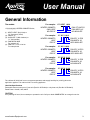
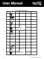
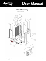
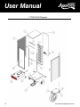
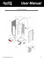
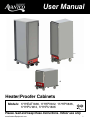
for Heated Cabinets Series
for Heated Cabinets Series
User Manual
177HEAT1836
177HPI1836
177HEAT1836
177HPI1836
177HPI1812
177HPI1812
Heater/Proofer Cabinets
100% Pre-Tested Electrical Assembly
1/20
100% Pre-Tested Electrical Assembly
Models: 177HEAT1836, 177HPI1812, 177HPI1836,
1/20
177HPU1812, 177HPU1836
08/2015
Please read and keep these instructions. Indoor use only.
www.AvantcoEquipment.com1
User Manual
Index
General Information .............................................................................4
Installation.............................................................................................4
Maintenance .........................................................................................4
Operating Instructions..........................................................................5
Service Specifications..........................................................................6
Recommended Temperature Guidelines-Food Holding Chart...........7
Drawer Assembly ............................................................................8-10
Cabinet Assembly ......................................................................... 11-16
Electric Schematic Power Supply ................................................ 17-18
Troubleshooting ................................................................................. 19
SAFETY INFORMATION:
WARNING: Follow all food safety guidelines. Pre-heat the cabinet to the desired temperature before placing cooked,
hot food into the cabinet. This is not a re-thermalizing cabinet. Food must be at the appropriate
temperature before being placed in to this cabinet. Use a food probe to check internal food
temperature—the cabinet temperature is not necessarily the internal food temperature.
WARNING: Only factory approved service agents should attempt to service, repair or replace electrical
components, wiring or power cord.
WARNING: Unplug the cabinet before cleaning or servicing. Do not wash the cabinet with a water jet or high
pressure water.
WARNING: This cabinet is for hot food holding applications only.
CAUTION: Do not spray or pour water into the module. To clean the cabinet, wipe with a damp cloth and dry with a
towel. Use only cleaning agents approved for aluminum.
CAUTION: Water dripping onto the floor from open doors can be a slip hazard.
2www.AvantcoEquipment.com
User Manual
General Information
The models:
177(1)(2)(3)(4)(5) HEATED CABINETS Series,
(1) - H
EAT “HEAT” (Only Heat) or
“H” (Commonly Used)
(2) - PROOF “P”
(3) - INSULATE “I”(With Insulate) or
“U” (No Insulate)
(4) - PAN WIDTH INCH
For example 18”
(5) - P
AN QTY - From: 12 to 36
For example: 36
For example:
177 HEAT 18 36
HEATED CABINETS
ONLY HEAT
NO PROOF
For example:
PAN QTY 36 PCS
PAN WIDTH 18"
NO INSULATE
177 H P I 18 12
HEATED CABINETS
HEAT
PROOF
For example:
PAN QTY 12 PCS
PAN WIDTH 18"
WITH INSULATE
177 H P I 18 36
HEATED CABINETS
HEAT
PROOF
For example:
PAN QTY 36 PCS
PAN WIDTH 18"
WITH INSULATE
177 H P U 18 12
HEATED CABINETS
HEAT
PROOF
For example:
HEATED CABINETS
HEAT
PROOF
PAN QTY 12 PCS
PAN WIDTH 18"
NO INSULATE
177 H P U 18 36
PAN QTY 36 PCS
PAN WIDTH 18"
NO INSULATE
The cabinet will hold food hot at a constant temperature and supply humidity for proofing when the
application applies. This cabinet is NOT a cooking appliance.
Heat Unit Specifications
Removable bottom mount proof / heat unit (Part No. HCD1500) or only heat unit (Part No. HCD1500H).
Rated Power: 1500 W, 120V, 60HZ
CAUTION
If any damage is found, do not attempt to operate the unit. Call your dealer IMMEDIATELY to arrange for service.
www.AvantcoEquipment.com3
User Manual
Installation
INSTALLATION
Position your unit on a stable, level surface and plug in the supplied cord into any grounded 120-volt
AC, 15
amps
supply
dedicated
braker.
highly
recommended
that
you use120-Volt
ONLY the
Position
your
unitpower
on a stable,
level
surface and
plugItinisthe
supplied
cord into any
grounded
AC,power
15 amps
power
dedicated
It is highly
recommended
that youoperational
use ONLY the
power cord
Usethe
of a
cordsupply
supplied.
Use ofbreaker.
a dedicated
circuit
will help to insure
efficiency.
Do supplied.
not operate
dedicated circuit will help to insure operational efficiency. Do not operate the unit with an extension cord.
unit with an extension cord.
15Amp Outlet
15Amp
For Cabinet
ratedOutlet
120V 1500Watt
For Cabinet rated 120V 1500Watt
Maintenance
MAINTENANCE
The equipment has been designed to require minimum maintenance and has been constructed to
meet
National
Foundation
and
U.S. Public
Health Service
standards.
Non-toxic
chemical
The
equipment
hasSanitation
been designed
to require
minimum
maintenance
and has been
constructed
to meet
National
cleanersFoundation
or mild detergents
are recommended
for cleaning
of fixtures.
DO NOT
useorsteel
wools of are
Sanitation
and U.S. Public
Health Service standards.
Non-toxic
chemical
cleaners
mild detergents
recommended
for cleaning
of fixtures.
NOTinto
usethe
steelgrains
wools of
of any
wool corrosion.
particles willAlso,
work these
into the
any kind. Steel
wool particles
willDO
work
the kind.
metalSteel
causing
grains of the metal causing corrosion. Also, these particles can cause a health hazard. If scouring is required, use a
particles can cause a health hazard. If scouring is required, use a non-abrasive type of cleaner. Do
non-abrasive type of cleaner. Do not use caustic solutions on your equipment. Hosing or steam cleaning should not be
not use to
caustic
solutions
on your
steam
cleaning
should
notinto
be necessary
necessary
keep these
fixtures
cleanequipment.
and sanitary.Hosing
Do notor
allow
water
or steam
to come
contact withkeep
electrical
components.
Never
power
wash
or steam
cabinet
electrical
cordinto
plugged
in. with electrical
these fixtures
clean
and
sanitary.
Doclean
not the
allow
waterwith
or the
steam
to come
contact
components. Never Power wash or steam clean the cabinet with the power drawer inserted.
CAUTION
BeCAUTION
sure to disconnect power source before cleaning and servicing the unit. Liability for improper or careless use is the
responsibility of the equipment owner or persons servicing the unit, including the authorized service agent.
Be sure to disconnect power source before cleaning and servicing the unit. Liability for improper or
careless use is the responsibility of the equipment owner or persons servicing the unit, including the
authorized service agent.
Attack tough grease, oil, and carbon with this ready to use cleaner and
degreaser. Its unique formula is designed to clean concrete, machinery,
engines, floors, walls, and more!
4www.AvantcoEquipment.com
User Manual
Operating
Instructions
Operating
Instructions
Operating
Instructions
A.
to
PLATE
for
electrical
requirements.
Cabinets
rated at
120V
1500
watts
must
A. Refer
Refer
totoDATA
DATA
PLATE
forelectrical
electrical
requirements.
Cabinets
at 1500
120Vwatts
1500
watts
must be
beinto a 125 VAC
A. R
efer
DATA
PLATE
for
requirements.
Cabinets
ratedrated
at 120V
must
be
plugged
plugged
into
a
125
VAC
15
amp
receptacle
and
must
be
used
on
an
individual
branch
circuit.
DO
plugged
into
a
125
VAC
15
amp
receptacle
and
must
be
used
on
an
individual
branch
circuit.
DO
15 amp
receptacle
and
must be used on an individual branch circuit. DO NOT MODIFY CORD PLUG.
NOT
MODIFY
CORD
PLUG.
NOT
MODIFY
CORD
PLUG.
B. With
POWERswitch
switchOFF,plug
OFF,
plug into
125
VAC
grounded receptacle.
B.
With
POWER
into
125
VAC
receptacle.
B. With
OFF,plug
intotap
125
VACforgrounded
grounded
receptacle.
C. Fwater
illPOWER
waterpan
panswitch
totop
top with
with clean
HOT
water
Proofing
or
if or
moisture
is desired
for Holding.
Check water level
C.
Fill
to
clean
HOT
tap
water
for
Proofing
if
is
for
C. Fillevery
water3 hours
pan to(2top
with
clean
HOT
tap
water
for
Proofing
ortap
if moisture
moisture
is desired
desired Water
for Holding.
Holding.
hours
when
Proofing)
and when
refill with
clean HOT
water
asclean
necessary.
pan as
does not have to
Check
water
level
every
3
hours
(2
hours
Proofing)
and
refill
with
HOT
tap
water
Check
water
level
every
3 hours
(2 hours
when
Proofing)
refill with clean HOT tap water as
be filled
for
Heating.
Proofing
requires
water
pan to
beHeating.
filled. and Proofing
necessary.
Water
pan
does
not
have
to
be
filled
for
requires
water
pan
to
be
necessary. Water pan does not have to be filled for Heating. Proofing requires water pan to be
filled.
filled.
HEATING INSTRUCTIONS
HEATING
HEATING INSTRUCTIONS
INSTRUCTIONS
②
③
①
②
③
①
(Only HEAT)
(Only HEAT)
②
②
③
③
Set
Combination
HEAT
1. Set
CombinationModule
Module switch
switch to
to HEAT
Set
Combination
Module
switch
to
HEAT
Set
POWER
switch
to
the
ON
position.
Power
indicator
light.
2. Set
POWERswitch
switch to
to the
the ON
light
will turn on.
Set
POWER
ON position.
position.Power
Powerindicator
indicator
light.
Set
TEMPERATURE
control
to
9..
3.
Set
TEMPERATURE
control
to
9.
Set TEMPERATURE control to 9..
Pre-heat
until
desired
temperature
is
from
77°(25
℃
))
4. P
re-heatcabinet
cabinet until
is reached
(typical(typical
heat-upheat-up
time fromtime
77°(25C)
is
Pre-heat
cabinet
untildesired
desiredtemperature
temperature
is reached
reached
(typical
heat-up
time
fromambient
77°(25to
℃160°(71C)
ambient
to
160°(71
℃
)
is
approximately
45
minutes).
Cabinet
with
insulate
temper
ature
is
reached
approximately
45
minutes).
Cabinet
temperature
reaches
185°(85C)
within
approximately
45
minutes
ambient to 160°(71℃) is approximately 45 minutes). Cabinet with insulate temperature is reached
185°(85°C)
approximately
45
5. Re-set TEMPERATURE
control
and adjust as necessary to reach desired temperature (setting
185°(85°C)
approximately
45 minutes.
minutes.
5. Re-set
TEMPERATURE
control
and adjust as necessary to reach desired temperature (setting
6-8
is
typical
for
150°(66C)
to
160°(71C).
5. Re-set TEMPERATURE control and adjust as necessary to reach desired temperature (setting
6-8
is
typical
for
150°(66
℃
)
to
160°(71
6-8 is typical for 150°(66℃) to 160°(71℃
℃)).
)).
PROOFING
INSTRUCTIONS
PROOFING
INSTRUCTIONS
PROOFING
INSTRUCTIONS
②
③
④
②
③ ①
① ④
1.
1.
2.
2.
3.
3.
4.
4.
1.
1.
2.
2.
3.
3.
4.
4.
5.
5.
6.
6.
1. Set Combination Module switch to PROOF
Set
Module
to
2.
SetCombination
POWER switch
to the switch
ON position.
Power indicator light will turn on.
Set
Combination
Module
switch
to PROOF
PROOF
Set
POWER
switch
to
the
ON
position.
3.
Set
TEMPERATURE
control
to
2.
Set POWER switch to the ON position. Power
Power indicator
indicator light.
light.
Set
TEMPERATURE
control
to
2.
4.
SetTEMPERATURE
HUMIDITY controlcontrol
to 9. to 2.
Set
Set
HUMIDITY
control
to
5.
P
re-heat
cabinet
until desired
Set
HUMIDITY
control
to 9.
9. temperature and humidity is reached (typical heat-up time from 77°(25C) ambient to
Pre-heat
cabinet
until
desired
temperature
and
is
95°(35C)
and
95%
relative
humidity
is approximately
30 minutes).
Pre-heat cabinet until desired
temperature
and humidity
humidity
is reached
reached (typical
(typical heat-up
heat-up time
time from
from
77°(25
℃
)
ambient
to
95°(35
℃
)
and
95%
relative
humidity
is
approximately
30
minutes).
6.
Adjust℃settings
as necessary
to) reach
desired
temperature
and
levels. 30 minutes).
77°(25
) ambient
to 95°(35℃
and 95%
relative
humidity
is humidity
approximately
Adjust
Adjust settings
settings as
as necessary
necessary to
to reach
reach desired
desired temperature
temperature and
and humidity
humidity levels.
levels.
NOTE: The internal air circulation blower and 1500W heater element (controlled with the Heat Thermostat) will operate
continuously when the power switch is turned ON.
www.AvantcoEquipment.com5
NOTE:
NOTE: The
The internal
internal air
air circulation
circulation blower
blower and
and 1500w
1500w heater
heater element
element (controlled
(controlled with
with the
the Heat
Heat
User Manual
HEAT THERMOSTAT
The controlling range is 80°F to 185°F. The dial numbers, 1 thru 9, do not relate to a specific calibrated temperature.
Temperature settings must be obtained through familiarization with the unit. The dial also has an OFF position to turn
heater unit off.
HUMIDITY THERMOSTAT
To control humidity range from 30% to 100%, humidity settings must be obtained through familiarization with the unit.
The dial numbers, 1 thru 9, do not relate to a specific calibrated humidity. The dial also has an OFF position to turn
humidity off. To maintain low heat range between 85°F to 100°F, switch to proof mode and adjust heat knob to desired
heat range. Allow 45 minutes to pre-heat in proof cycle.
Service Specifications
The Heater-Proofer is an aluminum transport cabinet with heaters to function as a hot food holding cabinet, and/or as a
proofing cabinet.
The heater, or heat drawer, is slid into place on the lower ledges of the cabinet. An electrical power cord is provided
and plugged into the drawer through an access hole in the back of the cabinet. The main power switch on the front of
the drawer, when switched ON, will turn on the light in the switch and turn on the air circulating fan in the drawer. The
circulating fan and 1500W heater element will operate continuously while the unit is ON.
The thermostat control knobs are mounted to the left and right of the HEAT/PROOF switch. The left thermostat knob
controls the heat in the cabinet from 1 (approx. 30% relative humidity) to 9 (100% relative humidity). Average setting is 6
(approx. 85% relative humidity).
6www.AvantcoEquipment.com
User Manual
Recommended Temperature
Guidelines Food Holding Chart
Food Product
Covered/Uncovered
Temperature Setting
Baked Fish
Uncovered
175°F (79°C)
Baked Potatoes
Uncovered
180°F (82°C)
Biscuit
Covered
180°F (82°C)
Broccoli
Uncovered
170-175°F (77-79°C)
Chicken Nuggets
Covered
175°F (79°C)
Corn on the Cob
Uncovered
170-175°F (77-79°C)
Croissants
Covered
175°F (79°C)
Egg Patties
Uncovered
180°F (82°C)
French Fries
Uncovered
185°F (85°C)
Fried Chicken
Uncovered
180-185°F (82-85°C)
Fried Fish
Uncovered
180°F (82°C)
Hamburgers
Covered
180°F (82°C)
Lasagna
Covered
185°F (85°C)
Mashed Potatoes
Covered
175°F (79°C)
Mixed Veggies
Covered
170-175°F (77-79°C)
Pancakes
Covered
175°F (79°C)
Pastas
Covered
180°F (82°C)
Peas
Covered
170-175°F (77-79°C)
Pizza
Uncovered
175-180°F (79-82°C)
Roast Beef
Uncovered
170-180°F (77-82°C)
Roast Pork
Uncovered
170-180°F (77-82°C)
Scalloped Potatoes
Covered
175°F (79°C)
Strip Steak
Uncovered
160-170°F (71-77°C)
Turkey
Uncovered
170-180°F (77-82°C)
Waffles
Covered
175°F (79°C)
Whole Chicken
Uncovered
170-180°F (77-82°C)
www.AvantcoEquipment.com7
User Manual
Drawer Assembly
HCD1500 Drawer Diagram
8www.AvantcoEquipment.com
User Manual
HCD1500H Drawer Diagram
HCD1500H Drawer Diagram
www.AvantcoEquipment.com9
User Manual
Drawer Replacement Parts
Item#
Photo
Part No.
Part Description
HCD1500 Qty HCD1500H Qty
03
HCD-030
Cable Bushing
1
1
04
HCD-031
Power Cable
1
1
05
HCD-026
Terminal Block
1
1
14
HCD-035
Knob
2
1
15
HCD-024
Thermometer
1
1
16
HCD-016
Main Switch
Switch
Main
with with
Red
lightLight
Red
1
1
18
HCD-019
Limit
1
1
Temp.
Thermostat
19
HCD-034
Temp. Thermostat
2
1
20
HCD-017
Transformer
1
1
27
HCD-011
Heating element
1
1
1
1
900W
26
HCD-010
Heating element
600W
29
HCD-008
SS Water Pan
1
N/A
32
HCD-009
Heating element
1
N/A
1
N/A
600W
36
HCD-036
Heat/Proof
Switch
Switch Heat/Proof
with
Red Red Light
11/20
10www.AvantcoEquipment.com
User Manual
Cabinet Assembly
177HPI1836 Diagram
12/20
www.AvantcoEquipment.com11
User Manual
177HPU1836 Diagram
12www.AvantcoEquipment.com
User Manual
177HEAT1836 Diagram
www.AvantcoEquipment.com13
User Manual
177HPU1812 Diagram
14www.AvantcoEquipment.com
User Manual
177HPI1812 Diagram
www.AvantcoEquipment.com15
User Manual
Cabinets Replacement Parts
Item#
Replacement Part No.
Description
07
HC1812HP-04
Hang Panel
Quantity
1
07
HC1836HP-04
Hang Panel
1
Magnetic Strip for door
Magnetic Strip
strip
((Include
Includetop
top1pc,
1pc,
Right/Left
side
2pcs)
Right/Left side 2pcs).
1
Magnetic Strip
(Include
top 1pc,
strip(
Include
top
Right/Left side 2pcs)
1pc, Right/Left side
1
08/09
1812
08/09
Magnetic Strip for door
1836
2pcs).
Use for Cabinets
177HPU1812
177HPI1812
177HEAT1812
177HEATI1812
177HPU1836
177HPI1836
177HEAT1836
177HEATI1836
177HPU1812
177HPI1812
177HEAT1812
177HEATI1812
177HPU1836
177HPI1836
177HEAT1836
177HEATI1836
177HPU1812
177HPI1812
177HEAT1812
177HEATI1812
177HPU1836
177HPI1836
177HEAT1836
177HEATI1836
All
10
HC1812HP-06
Door Assembly
1
10
HC1836HP-06
Door Assembly
1
11
HC1836HP-07
Hinge
2
12
HCD1500
Heat/proof drawer
1
12
HCD1500H
Only Heat drawer
1
13
Plastic Pan
Plastic Pan Black
14
Caster
5” Caster with Brake
1
4
177HPU1836
177HPI1836
177HPU1812
177HPI1812
177HEAT1836
177HEATI1836
177HEAT1812
177HEATI1812
All
All
4
All
(Include Hardware)
15
HC1836HP-029
Bumper
16www.AvantcoEquipment.com
User Manual
Electric Schematic Power Supply
HEAT/PROOF Models (HCD1500 Drawer)
www.AvantcoEquipment.com17
User Manual
Only HEAT Models (HCD1500H Drawer)
18www.AvantcoEquipment.com
User Manual
Troubleshooting
CAUTION
Before disassembling unit, electrical power must be disconnected by unplugging the unit. Failure to unplug the unit
prior to servicing may result in electrical shock.
Each unit is shipped with this instruction manual and should be used as a reference guide for all service areas. The
manual provides a picture of the drawer, showing the location of electrical components and a description of each. If the
unit does not operate correctly, or malfunctions for any reason, the following check list should provide a solution.
1) Check to make sure power cord is firmly plugged into the wall outlet.
2) Check circuit breaker of wall outlet and reset if necessary.
IF unit fails to start, please do the following:
3) Remove heat drawer from cabinet. Remove bottom cover of drawer. Visually inspect to observe for:
a. Loose or disconnected wires
b. Black or burnt marks on any components
c. Loose heating elements
4) If any burn marks or discoloration of wires is noted on any component, the component along with all wires attached
to the damaged component must be replaced.
5) If a heater element is loose, or if it has broken loose from mounting tabs, the wires will short out on the metal,
causing permanent damage. Both the element and main power switch (with wires on switch) must be replaced.
6) If the temperature on the LED Thermometer is not reading a constant temperature, it must be replaced along with its
power supply transformer.
Limited Warranty
All equipment which is sold under Avantco trademark and used for commercial purpose is warranted against defects
in materials and workmanship. The warranty runs for one year from the date of original installation and is for the benefit
of the original purchaser only. All other Warranties, Expressed or Implied, Statutory or Otherwise, including Without
Limitation any implied Warranty of Merchantability or Fitness for Purposes, are excluded. The Seller shall in no event be
liable for direct, indirect or consequential damages in connection with Avantco commercial products.
This warranty is not effective if damage occurs because of accident, carelessness, improper installation, lack of
proper set – up, supervision when required or if the equipment is installed or operated in any manner contrary to the
installation and operating instructions. In these cases, repairs will be made at a reasonable cost. Work performed by
unauthorized personnel or unauthorized service agencies voids this Warranty.
1 year warranty applies to electrical components. Defects in any non-electrical components will be covered within 90
days of the purchase date.
This warranty does not apply to, and Avantco is not responsible for, any warranty claims made on products sold or used
outside of the United States.
www.AvantcoEquipment.com19