1
PlateLoc™ User Manual
version 2.1
435 Acacia Avenue
Palo Alto, CA 94306
(650) 846-6500
www.velocity11.com
Information in this document is subject to change without notice
copyright © 2001 by Velocity11
Reproduction in any manner whatsoever without the written permission
of Velocity11 is strictly forbidden.
Microsoft and Windows are registered trademarks of Microsoft
Corporation.
Other trademarks and trade names may be used in this document to refer
to either the entities claiming the marks and names or their products.
Velocity11 disclaims any proprietary interest in trademarks and trade
names other than its own.
Rev. 2.1
October 2001
PlateLoc User Manual
Table of Contents
Chapter 1: General Information .................................................................................................................... 5
Introduction ......................................................................................................................................... 5
System Requirements ......................................................................................................................... 5
Warranty Information and Service Contracts ..................................................................................... 6
Warnings and Advisories .................................................................................................................... 6
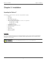
Chapter 2: Installation .................................................................................................................................... 7
Unpacking the PlateLoc™ .................................................................................................................. 7
Installation .......................................................................................................................................... 8
Setting up the PlateLoc™ ................................................................................................................... 11
Cold Running the PlateLoc ................................................................................................................. 14
Chapter 3: Plate Sealing ................................................................................................................................. 17
Selecting a Plate Locator Insert .......................................................................................................... 17
Using the LCD Touch Screen ............................................................................................................. 18
Setting Seal Time and Temperature .................................................................................................... 19
Manually Sealing a Microplate ........................................................................................................... 20
Chapter 4: Active X Documentation ............................................................................................................. 23
Installing PlateLoc Software ............................................................................................................... 23
Properties ............................................................................................................................................ 24
State Codes ......................................................................................................................................... 27
Methods .............................................................................................................................................. 31
Events .................................................................................................................................................. 34
Chapter 5: Maintenance ................................................................................................................................. 37
General Maintenance Schedule .......................................................................................................... 37
Cleaning the Hot Plate ........................................................................................................................ 38
Changing the Seal Roll ....................................................................................................................... 38
Reloading Seal Material into a Hot Machine ...................................................................................... 39
Overall Machine Cleaning .................................................................................................................. 41
Changing the NAFD2000 Filter ......................................................................................................... 41
Inspecting the Cutter ........................................................................................................................... 43
Lubricating the Door Hinges .............................................................................................................. 43
Table of Contents
PlateLoc User Manual
Chapter 6: Troubleshooting ...........................................................................................................................45
Power and LCD Touch Screen Problems ...........................................................................................45
Air Problems .......................................................................................................................................46
Sealing Problems .................................................................................................................................46
Seal Material Feeding Problems .........................................................................................................47
PlateLoc Error Messages ....................................................................................................................48
Appendix A .......................................................................................................................................................51
Velocity11’s Product Warranty ..........................................................................................................51
Table of Contents
PlateLoc User Manual
Chapter 1: General Information
Chapter 1: General Information
Introduction
Thank you for purchasing a Velocity11 PlateLoc thermal plate sealer. The PlateLoc is a self-contained module for applying
thermal seals to microplates. These seals prevent contamination and evaporation of valuable samples during transport or storage.
The PlateLoc consistently achieves a high quality seal with its sophisticated thermal control system. The PlateLoc needs no
adjustment to seal plates of various heights. The PlateLoc’s small footprint allows easy robotic integration, and its touch screen
display enhances usability in manual applications. Above all, the PlateLoc's processing time and operating costs are significantly
less than competing products, making it the optimal solution for both manual and automated sealing applications.
The purpose of this guide is to provide the basic information necessary to achieve the optimal performance from your PlateLoc.
Whether your application is manual plate sealing, or integration into a larger automation platform, this user’s manual will walk you
through the required steps to get your unit working to its fullest capacity.
Velocity11 strives to produce the highest throughput and highest quality products available for the laboratory automation market.
Technical information on the PlateLoc and other exciting Velocity11 products are available from Velocity11. With questions or
comments, please contact our Service Center at (650) 846-6500 or visit our website at: http://www.velocity11.com.
System Requirements
Stand Alone Unit
• 8.5” x 13.5” benchspace
• 1/4” compressed air line capable of supplying 2.5 cfm at 90 psi with 0.05 µm filtration
• 120 VAC, 50-60 Hz, 5 amps (factory installed 220 VAC models are also available)
Automated Platform
• Same as the stand alone unit above
• Pentium 166 or better PC
• Windows NT4, Service Pack 6 or Windows 2000
• 32 MB RAM
• Serial I/O RS-232 9 pin connector
5
PlateLoc User Manual
Chapter 1: General Information
Warranty Information and Service Contracts
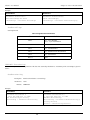
All Velocity11 products are covered under warranty for parts and labor for the first year of service (see table 1).
Table 1: Velocity11 Standard Service Warranty
Standard Service
Shippable Items
Non-Shippable
Items
The damaged unit will be shipped to Velocity11 for
repair. Upon repair, the unit will be shipped back to you.
A technician will be dispatched to your site the next
business day, not including holidays.
For the product warranty for this PlateLoc, please refer to “Velocity11’s Product Warranty” on page 51”.
Warnings and Advisories
Your safety while utilizing the PlateLoc is of paramount importance to Velocity11. Carefully read and follow all warnings and
cautions that are outlined in this manual. The PlateLoc must only be used in the manner in which it was intended by Velocity11.
Any other use of the PlateLoc may cause damage to the product, samples, or harm to the user. Take note of the following signs.
They call attention to a procedure that if not correctly performed, could result in a hazardous condition or damage all or part of the
product. Do not proceed beyond a warning label until the indicated conditions are fully understood and met.
WARNING
CAUTION
NOTE
Warning signs signal procedures that will potentially cause bodily harm or death
if not performed correctly.
Caution signs signal procedures that will potentially cause damage to the
instrument if not performed correctly.
Note signs indicate points that are important in order to correctly setup or use the PlateLoc. No
danger is involved.
This unit is currently being evaluated and tested for full CE and UL certification.
Any modifications or changes to the PlateLoc not expressly approved in this manual could void your warranty and authority to
operate this equipment.
6
PlateLoc User Manual
Chapter 2: Installation
Chapter 2: Installation
Unpacking the PlateLoc™
The following is a complete list of the contents of the Velocity11 PlateLoc packages.
•
•
•
•
•
•
•
•
•
•
•
•
•
PlateLoc
Seal material
Power cable
Serial communications cable
15 feet of 1/4” polyurethane tubing
Three hose fittings (optional depending on your house air configuration)
- 1/4” quick connect - 1/4” NPT
- 1/4” quick connect - 1/8” NPT
- 1/4” quick connect T
NAFD2000 0.01 µm air filter
NAFD2000 Filter Installation Instructions
Seal roll axle & hubs
Plate locator
Support inserts
PlateLoc User Manual
PlateLoc ActiveX CD
Inspection
Check that all items from the list above have been included in the PlateLoc packages. Inspect all items for possible shipping
damage before continuing the installation process. If anything is missing or appears damaged, contact a Velocity11 service
representative as soon as possible.
NOTE
Save the carton and packing materials in case you ever need to ship the unit.
7
PlateLoc User Manual
Chapter 2: Installation
Installation
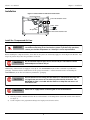
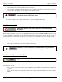
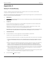
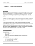
Figure 1: Control Panel Air and Power Connections
Pneumatic Gauge
Pneumatic ON/OFF Switch
ON
OFF
Power Switch
(ON
OFF)
Power Port
Serial Communications Port
Air Input Port
Install the Compressed Air Line
WARNING
Working with open, charged air lines can result in injury. Proper procedure
should be used to bring an air line into the system. If you have any questions,
contact your facilities department or a Velocity11 service representative.
Before installing the compressed air line, ensure that the air system can consistently supply 2.5 cfm at 90 psi to the PlateLoc. Any
drop in air pressure may reduce the performance of the unit.
CAUTION
Do not allow the input air pressure to exceed 145 psi. The PlateLoc cannot
withstand pressure above 145 psi.
Additionally, confirm that the air supply is clean, dry air. The NAFD2000 0.01 µm air filter is included in your PlateLoc
packaging. This filter must be installed in the air line going to the PlateLoc. A detailed instruction sheet on installing the
NAFD2000 0.01 µm air filter is included in your PlateLoc packaging.
CAUTION
CAUTION
Ensure that the air line coming into the PlateLoc is filtered from moisture and
oil. Significant moisture or oil can adversely affect the life of the unit. The
NAFD2000 air filter is included with the PlateLoc to help filter out excess oil
from the air flow.
Switch off air supply before connecting the air line to the PlateLoc.
1) Turn the pneumatic ON/OFF switch on the rear of the PlateLoc to the OFF position (toward the outside of the machine.
See figure 1).
2) Cut two lengths of 1/4” polyurethane tubing to the length you need for the air line.
8
PlateLoc User Manual
Chapter 2: Installation
3) If your air supply uses a threaded fitting, attach the 1/4” NPT fitting to the nozzle. Attach the 1/4” one touch hose fitting
into the 1/4” tubing. If your lab already uses 1/4” tubing, use the T fitting to connect to the existing tubing as close to the
source as possible.
CAUTION
For more detailed instructions on installing the NAFD2000 air filter with your air
supply line, refer to the sheet “Installing Your NAFD2000 Air Filter” included
with your PlateLoc.
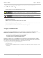
4) Attach the other end of the 1/4” tubing to the quick relesase input of the included NAFD2000 air filter (see figure 2). Tug
gently on the line. If you feel resistance, the line has been properly installed.
5) Attach one end of a second length of 1/4” tubing to the quick release output of the NAFD2000 air filter. Tug gently on the
line to ensure it has been properly installed.
CAUTION
The ARROW on the top side of the NAFD2000 filter indicates the direction in
which air should flow through the filter. Attaching the filter incorrectly will
cause damage to the filter.
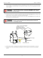
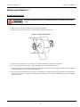
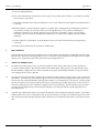
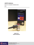
Figure 2: Air Line Layout Diagram
The ARROW on the top of
the filter indicates the direction
in which air should flow through
the filter.
1/4” Polyurethane Tubing
From Air Supply
NAFD2000 Filter
PlateLoc
Automatic Bleed Valve
Air Input Port
6) Insert the other end of the 1/4” tubing into the quick release air input port on the back of the PlateLoc (see figure 1).
7) Tug gently on the air line after installing it into the PlateLoc. If you feel resistance, then the line has been properly
installed.
9
PlateLoc User Manual
Chapter 2: Installation
8) Turn on the air supply. Listen for leaks in the air line connections.
9) Turn the pneumatic ON/OFF switch for the PlateLoc to the ON position (toward the inside of the machine, see figure 1).
When you turn the air supply on, the door will open and the stage will extend.
When you turn the air supply on, the door will open and the stage will extend.
Keep the area in front of the PlateLoc clear.
WARNING
10) Check the pneumatic gauge on the rear of the PlateLoc to ensure it reads approximately 90 psi.
Install the Power Cable
CAUTION
Operating the PlateLoc at the wrong voltage could seriously damage the
instrument.
Before turning on the system, ensure that the voltage supplied to the PlateLoc system is 120 VAC, 50-60 Hz, and the line is rated
to supply a minimum of 5 amps. Also ensure that the red box directly above the power switch reads 120V. If it does not, contact
your Velocity11 service representative. 220 VAC models of the PlateLoc are available but must be factory installed. Contact
Velocity11 for more details.
1) Turn the power switch on the back of the PlateLoc to OFF position (see figure 1).
2) Plug one end of the power cable into the 120 VAC power port on the rear of the PlateLoc (see figure 1).
3) Plug the other end of the power cable into a grounded electrical socket.
WARNING
The PlateLoc is an automated piece of equipment with moving parts. Ensure
that hair, clothing, and jewelry do not become caught in the machine.
Install the Serial Communications Cable
NOTE
For automated control users only. If you are only using the PlateLoc manually, skip this
section.
The serial communications cable is only necessary if you wish to command the PlateLoc remotely or if the PlateLoc is part of an
integrated robotic system.
1) Plug one end of the serial communications cable into the RS-232 serial communications port on the rear of the PlateLoc
(see figure 1).
2) Plug the other end of the serial communications cable into the available serial port on the PC you will use to control the
PlateLoc.
10
PlateLoc User Manual
Chapter 2: Installation
Setting up the PlateLoc™
Mounting the Seal Roll
CAUTION
Before mounting the seal roll, ensure that the power is off and the air pressure
is on.
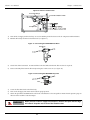
1) Remove the seal roll, seal roll hubs, and axle from their packaging.
2) Take one of the seal roll hubs and screw it 15 to 20 turns onto the seal roll axle.
Figure 3: Seal Roll Axle and Hubs
Seal Roll Hubs
Seal Roll
Seal Roll Axle
3) Place the seal roll onto the axle (see figure 3). The roll should fit snugly against the seal roll hub.
4) Screw the second hub onto the axle. Tighten until the hubs are securely holding the roll.
5) Using scissors, make a clean straight cut across the end of the seal material, cutting off any part of the seal that is wrinkled
or torn. The PlateLoc will not work with wrinkled seal.
6) Place the seal roll with hubs and axle onto the seal roll supports. The roll should be placed so that the seal feeds from the
underside of the seal roll, as opposed to feeding from the top of the roll. The roll fits tightly between the two seal roll supports (see figure 4).
11
PlateLoc User Manual
Chapter 2: Installation
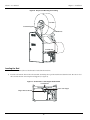
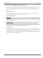
Figure 4: Proper Seal Mounting and Loading
Seal Roll
Seal Roll Supports
Seal Roll Hub
Seal Roll Slot
Loading the Seal
After the seal roll is mounted, the seal itself must be loaded into the machine.
1) Feed the seal from the front of the roll toward the back along the top of the machine and down the back. Be sure to feed
the seal under the bar connecting the roll supports (see figure 4).
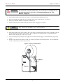
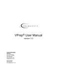
Figure 5: Control Panel - Seal Gripper Detailed View
Seal Roll Slot
Lower Seal Gripper
Gripper Release Button
12
PlateLoc User Manual
WARNING
Chapter 2: Installation
The following procedure for loading the seal roll should ONLY be followed when
the machine is cold (room temperature). For instructions on reloading the seal
roll while the machine is hot, refer to “Reloading Seal Material into a Hot
Machine” on page 39.
2) Press the silver gripper release button (see figure 5). You should hear the gripper snap closed.
3) Open the seal gripper by pushing the lower seal gripper down until it clicks into place (see figure 5).
4) Using a pen or marker, mark the seal material 7” from the end.
5) Feed the material into the seal roll slot directly above the lower seal gripper (see figure 5).
NOTE
If you have problems loading the seal, ensure that the edge entering the machine has not curled
down. Curl the edge up by hand to remove any downward curl.
6) Look into the front opening of the machine. After a few inches of seal material have been fed in, you should see the seal
material emerging into the main sealing chamber. Keep feeding the seal material until the 7” mark just disappears.
Ensure that the emerging edge of the seal is centered.
7) Close the seal gripper by pressing the silver gripper release button under the gripper. You should hear the gripper snap
closed.
8) Gently roll any slack back up into the seal roll. Be careful not to pull the seal out of the machine. The seal should look
like the example in figure 6 when loaded correctly.
Figure 6: Properly Loaded Seal Roll
Loaded
Seal Material
PlateLoc
13
PlateLoc User Manual
Chapter 2: Installation
Cold Running the PlateLoc
After installing the PlateLoc, the machine should be cycled five times at a cold temperature and without a plate. This ensures that
the PlateLoc is functioning properly and the seal material is feeding correctly.
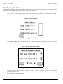
1) Turn on power to the PlateLoc by switching the power switch at the rear of the machine to the ON position. The LCD
touch screen will turn on and display the Main Menu as shown in figure 7.
Figure 7: PlateLoc Main Menu
0.5 S
30 C
2) Press Setup on the Main Menu. This will take you to the Set Parameters Menu (see figure 8). To adjust the contrast of the
LCD screen, press the up or down arrow next to the symbol of the sun.
Figure 8: PlateLoc Set Parameters Menu
0.5 S
30 C
3) Ensure that the temperature is set to 30 °C and time is set to 0.5 s. Use the up or down arrows next to the corresponding
paramter to adjust the value.
4) Press Done to return to the Main Menu.
14
PlateLoc User Manual
Chapter 2: Installation
5) The PlateLoc may take a few minutes to reach the temperature setting. The Status display in the Main Menu will indicate
whether the Machine is “Warming Up”, “Cooling Down”, or “Ready”.
.
NOTE
The RUN button remains blank until the temperature reaches the required level.
6) When the RUN button appears, press RUN to execute a cold cycle test of the PlateLoc.
NOTE
Do not hold your finger on the RUN button. This button is also used to stop a cycle.
7) The door will automatically close and you will hear air being released within the machine. The door will automatically
open and shuttle the tray outward when the cycle is complete.
8) The“No Plate in Holder” error message will appear on the LCD indicating that no plate was found in the machine. Press
Clear to return to the Main Menu.
9) Remove the cut piece of seal material from inside the machine.
10) Repeat the cycle four more times.
15
PlateLoc User Manual
Chapter 2: Installation
16
PlateLoc User Manual
Chapter 3: Plate Sealing
Chapter 3: Plate Sealing
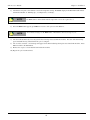
Selecting a Plate Locator Insert
Figure 9: Loading the Plate Locator and Insert
Plate
Support Insert
Plate Locator
Stage
1) Place the plate locator onto the three pins of the stage.
2) Place the support insert that best fits your plate type into the plate locator.
•
•
If the underside of the wells are flush with the bottom rim of the plate, use the 180 insert.
If the underside of the wells are not flush with the bottom rim of the pate, use an insert which will support the
underside of the wells and lift the bottom rim of the plate slightly above the plate locator surface (see figure 10).
Figure 10: Cross Section of Plate and Support Insert
Chimneys
Wells
PlateLoc Support Insert
NOTE
Plate
Always use the thinnest insert that will sufficiently support the wells.
17
PlateLoc User Manual
Chapter 3: Plate Sealing
Using the LCD Touch Screen
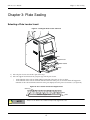
Use the LCD touch screen to control the PlateLoc manually.
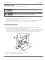
1) Tilt the LCD screen for easier viewing.
•
•
•
Press down on the screen release on the right side of the machine (see figure 11).
Pull the bottom of the screen out. Allow the screen release to click into place when the screen reaches its open
position.
To close, press down on the screen release and push the bottom of the screen. Allow the screen release to click into
place when the screen reaches its closed position.
Figure 11: Manual Sealing Preparation
LCD Screen (open)
Screen Release
Plate Locator
Door
2) Turn on power to the machine by switching the power switch to ON. The Main Menu will automatically appear on the
LCD touch screen (see figure 12).
3) Press the Setup buttton in the Main Menu to enter the Set Parameters menu (see figure 12).
4) The Set Parameters menu is used to set the sealing parameters as well as to adjust the screen contrast.
•
•
To adjust the contrast of the LCD screen, press the up or down arrow next to the symbol of the sun (see figure 12).
To adjust sealing parameters (seal time and seal temperature), press the up or down arrow on the screen next to the
parameter you wish to adjust (see figure 12).
5) Press the Done button in the Set Parameters menu to return to the Main Menu (see figure 12).
18
PlateLoc User Manual
Chapter 3: Plate Sealing
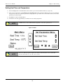
Setting Seal Time and Temperature
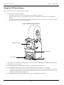
1) Press the Setup button on the Main Menu. This will take you to the Set Parameters Menu (see figure 12).
2) There are two parameters to set: Seal Time and Seal Temperature. These parameters differ for the type of seal and plate
being used (see table 2). To adjust the parameters, simply press the up or down arrow on the LCD touch screen next to the
parameter you wish to adjust.
3) Press Done to return to the Main Menu.
4) The PlateLoc will take approximately 2.5 minutes to reach sealing temperature.
NOTE
The RUN button remains blank until the temperature reaches the required level.
Figure 12: Menus
R
U
N
NOTE
The Service button is a password protected entrance into Velocity11’s service system. The
operator will not have access to the service system.
19
PlateLoc User Manual
Chapter 3: Plate Sealing
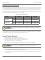
Standard Seal Times and Temperatures
The PlateLoc is designed to be used with as many different plates and seal materials as possible. Each type of plate and each type
of seal will require slightly different seal times and seal temperatures. The best way to determine settings for your PlateLoc setup
is to experiment with various times and temperatures until you find settings that provide a consistently good seal for your plates.
Locate your plate material and seal material in table 2. Use the standard seal time and seal temperature provided as a starting point
from which to determine the ideal temperature and time for your machine.
Table 2: Seal Times and Temperatures
Plate Type
Peelable Seal
Piercable Seal
Clear Seal
temp
180 °C
180 °C
150 °C
time
1.2 s
1.2 s
2.0 s
temp
170 °C
170 °C
150 °C
time
1.2 s
1.2 s
2.0 s
Polystyrene
Polypropylene
NOTE
When testing times and temperatures, it is recommended to hold the temperature constant and
cycle through a few different seal times since the PlateLoc takes some time to warm up and cool
down.
Check the Velocity11 web page for updates and further details on seal materials, seal temperatures, and seal times. To determine if
your settings have produced a good seal, refer to“Checking Seal Quality” on page 21.
Manually Sealing a Microplate
1) Ensure that all of the setup procedures have been followed.
2) Ensure that the temperature and sealing time have been set satisfactorily.
3) Ensure that the seal you have chosen is applicable for your kind of microplate.
4) Place a microplate in the plate locator. It should fit easily.
5) When the Status reads Ready on the Main Menu of the LCD touch screen (see figure 12), press RUN.
NOTE
Do not hold your finger on the RUN button. This button is also used to stop a cycle.
6) The plate will be shuttled into the machine. The shuttle door will close automatically. You will hear compressed air being
released and the pneumatic cylinders moving as the plate is processed.
7) The shuttle door will open, and the sealed plate will be shuttled out of the machine. Note that the seal on the plate will be
warm to the touch.
20
PlateLoc User Manual
WARNING
Chapter 3: Plate Sealing
The inside of the PlateLoc remains hot for approximately one hour after
being powered down.
Checking Seal Quality
To determine if the plate has been properly sealed:
1) Manually seal a plate.
2) After the plate has been sealed, wait five seconds for the plate and seal to cool down.
3) Remove the plate from the locator and carefully peel off the seal material from the plate.
4) Inspect the underside of the removed seal material. A plate that has been properly sealed will leave unbroken impressions
of each “chimney” on the underside of the seal material. If there are faint or broken impressions on the seal material, the
plate may need to be sealed for a longer time or at a higher temperature.
Visually inspect the plate. If the top of the plate looks overly melted, the plate may need to be sealed for a shorter time or at a
lower temperature.
21
PlateLoc User Manual
Chapter 3: Plate Sealing
22
PlateLoc User Manual
Chapter 4: Active X Documentation
Chapter 4: Active X Documentation
The PlateLoc is designed to allow easy integration into an automated system. An ActiveX control is provided that installs on your
computer, simplifying the programming needed to control the PlateLoc from your system. This document provides information on
how to use Velocity11’s ActiveX control within your Visual Basic or Visual C++ application. Please note that this documentation
is for ActiveX version 3.1, and that all example code assumes that the PlateLoc control is instantiated as PlateLoc1.
NOTE
For manual operation of the PlateLoc, please see “Manually Sealing a Microplate” on page 20.
Installing PlateLoc Software
1) Take the compact disc marked “PlateLoc ActiveX” from its case and insert it into the CD drive on your PC.
NOTE
For the highest performance from your PlateLoc, we recommend a Pentium 166 or better based
PC running Windows NT 4.0, Service Pack 6 or Windows 2000
2) Double-click Setup.exe. The InstallShield Wizard will appear.
3) Click Next. The Customer Information screen will appear.
4) Enter your name, company name, and PlateLoc serial number in the appropriate fields.
5) Click Next. The Choose Destination Location screen will appear.
6) The installation program will install the program on your C: drive unless you otherwise specify a location. To specify a
location, click Browse and choose the desired destination folder. Otherwise, click Next and skip to step 9.
7) When the folder has been specified, click Next. The Select Program Folder screen will appear.
8) Click Next if you want the specified folder. If not, select a new folder and then click Next.
9) The Setup Status Screen will appear. When InstallShield Wizard Complete appears, click Finish.
10) Follow the directions for your particular development environment for adding an ActiveX to your application.
The PlateLoc ActiveX has been installed in the folder you specified. You are now ready to run the PlateLoc ActiveX from your
computer.
23
PlateLoc User Manual
Chapter 4: Active X Documentation
Properties
short DesiredTemperature
DesiredTemperature is the temperature (in Celsius) needed to seal a plate.
GetDesiredTemperature
Description:
Retrieves the current temperature set point (in Celsius) saved in the PlateLoc. If an error
occurs, GetDesiredTemperature() will return -1 and an error event will be fired.
Parameters:
None
Returns:
short
Example:
Visual Basic
Visual C++
PlateLoc1.Initialize 2
’ sets the COM port to COM2
Dim desiredtemp As Short
desiredtemp =
PlateLoc1.DesiredTemperature
PlateLoc1.Initialize(2);
// sets the COM port to COM2
short iDesiredTemp;
iDesiredTemp =
PlateLoc1.GetDesiredTemperature();
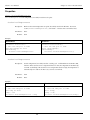
SetDesiredTemperature
Description:
Sets the temperature (in Celsius) used for a sealing cycle. Valid numbers are from 20 to 230,
inclusive. If the user tries to set a temperature that is too low, the temperature is automatically
set to 20 °C. Similarly, if the user tries to set a temperature that is too high, the temperature is
automatically set to 230 °C. In either case, an error event is fired.
Parameters:
short
Returns:
None
Example:
Visual Basic
Visual C++
PlateLoc1.Initialize 2
’ sets the COM port to COM2
Dim temp As Short
temp = 196
PlateLoc1.DesiredTemperature = temp
PlateLoc1.Initialize(2);
// sets the COM port to COM2
short itemp;
itemp = 196;
PlateLoc1.SetDesiredTemperature(itemp);
24
PlateLoc User Manual
Chapter 4: Active X Documentation
short CurrentTemperature
CurrentTemperature is the present temperature (in Celsius) of the hot plate.
GetCurrentTemperature
Description:
Retrieves the current temperature (in Celsius) of the PlateLoc’s hot plate. If an error occurs,
GetCurrentTemperature() will return -1 and an error event will be fired.
Parameters:
None
Returns:
short
Example:
Visual Basic
Visual C++
PlateLoc1.Initialize 2
’ sets the COM port to COM2
Dim temp As Short
temp = PlateLoc1.CurrentTemperature
PlateLoc1.Initialize(2);
// sets the COM port to COM2
short iTemp;
iTemp = PlateLoc1.GetCurrentTemperature();
SetCurrentTemperature
Not implemented.
double SealingTime
SealingTime refers to the length of time needed to seal a microplate in seconds.
GetSealingTime
Description:
Retrieves the current sealing time set in the PlateLoc’s memory. If an error occurs,
GetSealingTime() will return -1 and an error event will be fired.
Parameters:
None
Returns:
double
Example:
Visual Basic
Visual C++
PlateLoc1.Initialize 2
’ sets the COM port to COM2
Dim sealingtime As Double
sealingtime = PlateLoc1.SealingTime
PlateLoc1.Initialize(2);
// sets the COM port to COM2
double fSealingTime;
fSealingTime = PlateLoc1.GetSealingTime();
25
PlateLoc User Manual
Chapter 4: Active X Documentation
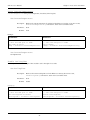
SetSealingTime
Description:
Sets the amount of time that the hot plate contacts the sealing foil. Valid numbers are from
0.5 to 12.0 seconds, inclusive. If a sealing time less than 0.5 seconds is specified, the sealing
time will automatically be set to 0.5 seconds and an error event will be fired. Similarly, if a
sealing time greater than 12.0 seconds is specified, the sealing time will automatically be set
to 12.0 seconds and an error event will be fired.
Parameters:
double
Returns:
None
Example:
Visual Basic
Visual C++
PlateLoc1.Initialize 2
’ sets the COM port to COM2
Dim sealingtime As Double
sealingtime = 2.3
PlateLoc1.SealingTime = sealingtime
PlateLoc1.Initialize(2);
// sets the COM port to COM2
double fSealingTime = 2.3;
PlateLoc1.SetSealingTime(fSealingTime);
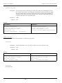
short State
State contains information about the PlateLoc’s current state of operation.
GetState
Description:
Retrieves the PlateLoc state code. Refer to table 3 for a list of valid state codes.
Parameters:
None
Returns:
short
Example:
Visual Basic
Visual C++
PlateLoc1.Initialize 2
’ sets the COM port to COM2
Dim state As Short
state = PlateLoc1.State
PlateLoc1.Initialize(2);
// sets the COM port to COM2
short iState;
iState = PlateLoc1.GetState();
SetState
Not implemented
26
PlateLoc User Manual
Chapter 4: Active X Documentation
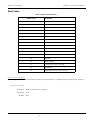
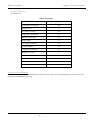
State Codes
Table 3: State Protocol Definitions
Definition
Status Code
0
Ready
1
Running
2
OutOfTemp
3
Error
4
Setup Screen
5
Password Screen
6
Service Screen (service use only)
7
AD Values Screen (service use only)
8
Actuation Screen (service use only)
10
Threshold Screen (service use only)
11
Timing Screen (service use only)
12
Return Actuators
13
Debounce
14
Waiting to Run
15
Config Screen (service use only)
16
Fatal Error
17
Temperature Screen (service use only)
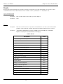
short ErrorFlags
ErrorFlags contain information about the last error asserted by the PlateLoc. A summary of the error flags is given in table 4.
GetErrorFlags
Description:
Retrieves the PlateLoc’s error flags.
Parameters:
None
Returns:
short
27
PlateLoc User Manual
Chapter 4: Active X Documentation
Example:
Visual Basic
Visual C++
PlateLoc1.Initialize 2
Dim iErrorFlags As Short
iErrorFlags = PlateLoc1.ErrorFlags
PlateLoc1.Initialize(2);
short iErrorFlags;
iErrorFlags = PlateLoc1.GetErrorFlags();
SetErrorFlags
Not implemented
Table 4: Flag Bit Protocol Definitions
Bit
Definition
Bit 0
Set— Cycle Finished
Clear— Cycle Not Finished
Bit 1
Set—Fatal Error
Bit 2
Set— Non-Fatal Error
Bit 3
Set— Insufficient Air/Vacuum Error
Bit 4
Set— Sensor Error
Bit 5-8
Spare
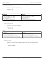
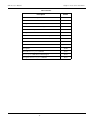
VARIANT ErrorString
ErrorString contains a text explanation of the last error asserted by the PlateLoc. A summary of the error strings is given in
table 5.
GetErrorString
Description:
Retrieves the PlateLoc’s error strings.
Parameters:
None
Returns:
VARIANT
Example:
Visual Basic
Visual C++
PlateLoc1.Initialize 2
’ sets the COM port to COM2
Dim ErrorString As String
ErrorString = PlateLoc1.ErrorString
PlateLoc1.Initialize(2);
// sets the COM port to COM2
VARIANT vErrorString;
vErrorString = PlateLoc1.GetErrorString();
CString sStatus;
sStatus = vErrorString.bstrVal;
28
PlateLoc User Manual
Chapter 4: Active X Documentation
SetErrorString
Not implemented
Table 5: Error Strings
Error String
Flag Bits Set
Transfer Plate Vacuum Error
2,3
Keystone Error
2
Low Air Pressure Error
2,3
Gripper Plate Vacuum Error
2,3
Hot Plate Vacuum Error
2,3
Overheat Error
2
Cycle Stopped Manually
2
No Plate in Holder
2,4
Temperature Sensor Error
2,4
Memory Access Error
1
Actuator Timeout Error
2
Serial Communications Error
2
Door Open During Cycle
2,4
Insufficient Vacuum Pressure
2,3
long ProcessTimeout
ProcessTimeout represents the allowable length of a sealing cycle in mS. If the cycle exceeds this length, an error is asserted. The
default timeout is 10000 ms (10 seconds).
29
PlateLoc User Manual
Chapter 4: Active X Documentation
GetProcessTimeout
Description:
Returns the current timeout in ms.
Parameters:
None
Returns:
long
Example:
Visual Basic
Visual C++
PlateLoc1.Initialize 2
’ sets the COM port to COM2
Dim iProcessTimeout As Long
iProcessTimeout =
PlateLoc1.ProcessTimeout
PlateLoc1.Initialize(2);
// sets the COM port to COM2
long iProcessTimeout;
iProcessTimeout =
PlateLoc1.GetProcessTimeout();
SetProcessTimeout
Description:
Sets a new process length in ms.
Parameters:
long
Returns:
None
Example:
Visual Basic
Visual C++
PlateLoc1.Initialize 2
’ sets the COM port to COM2
PlateLoc1.ProcessTimeout = 10000
’Set the process timeout to 10 seconds
PlateLoc1.Initialize(2);
// sets the COM port to COM2
PlateLoc1.SetProcessTimeout(10000);
//Set the process timeout to 10 seconds
ControlPicture
Description:
Retrieves a picture of the PlateLoc bitmap that can be used in the container’s application.
Parameters:
None
Returns:
IPictureDisp
30
PlateLoc User Manual
Chapter 4: Active X Documentation
Example: In this example, we will paint the PlateLoc bitmap over a button.
Visual Basic
Visual C++
’ Assume that there is a button named
’ Command1 on the current form. You
’ must set the Style property of
’ Command1 to “Graphical”
Command1.Picture =
PlateLoc1.ControlPicture
/* The CPicture class will be imported into
your project when the ActiveX is
installed */
CButton button; // Create a button
CPicture PlateLocPic;
PlateLocPic = PlateLoc.GetControlPicture();
// Retrieve the picture
button.SetBitmap((HBITMAP)
PlateLocPic.GetHandle());
// Paint the bitmap onto the button
Methods
Initialize
Description:
Initializes the COM port that the PlateLoc is attached to. This method must be called before any
other commands can be issued to the PlateLoc.
Parameters:
short
Returns:
None
Example:
Visual Basic
Visual C++
PlateLoc1.Initialize 2
’ sets the COM port to COM2
PlateLoc1.Initialize(2);
// sets the COM port to COM2
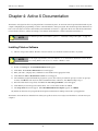
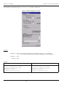
ShowDiagsDialog
Description:
Opens a dialog box that allows you to easily test the PlateLoc. From this dialog, you may set the
sealing time, sealing temperature, read the PlateLoc status codes, and start a sealing cycle.
Parameters:
None
Returns:
None
Example:
Visual Basic
Visual C++
PlateLoc1.Initialize 2
’ sets the COM port to COM2
PlateLoc1.ShowDiagsDialog
PlateLoc1.Initialize(2);
‘ sets the COM port to COM2
PlateLoc1.ShowDiagsDialog();
31
PlateLoc User Manual
Chapter 4: Active X Documentation
The following screen will appear when ShowDiagsDialog is called (see figure 13).
Figure 13: PlateLoc Diagnostics Screen
Close
Description:
Closes serial port used by the PlateLoc ActiveX. After calling Close, the method
Initialize must be called again before resuming communications with the PlateLoc.
Parameters:
None
Returns:
None
Example:
Visual Basic
Visual C++
PlateLoc1.Initialize 2
’ sets the COM port to COM2
PlateLoc1.SealingTime = 2.3
PlateLoc1.Close
’ Free up the serial port
PlateLoc1.Initialize(2);
// sets the COM port to COM2
PlateLoc1.SetSealingTime(2.3);
PlateLoc1.Close();
// Free up the serial port
32
PlateLoc User Manual
Chapter 4: Active X Documentation
StartCycle
Description:
Starts the PlateLoc sealing cycle.
Parameters:
None
Returns:
None
Example:
Visual Basic
Visual C++
PlateLoc1.Initialize 2
’ sets the COM port to COM2
PlateLoc1.StartCycle
PlateLoc1.Initialize(2);
// sets the COM port to COM2
PlateLoc1.StartCycle();
StopCycle
Description:
Aborts the current cycle.
Parameters:
None
Returns:
None
Example:
Visual Basic
Visual C++
Public Declare Sub Sleep Lib "kernel32"
Alias "Sleep" (ByVal dwMilliseconds As
Long)
PlateLoc1.Initialize(2);//Set up on COM 2
PlateLoc1.StartCycle();
// Start up a seal cycle
Sleep (1000); // Wait 1 second
PlateLoc1.StopCycle(); //Kill cycle
PlateLoc1.Initialize 2
’Set up on COM 2
PlateLoc1.StartCycle
’Start up a seal cycle
Sleep 1000
’Wait 1 second
PlateLoc1.StopCycle
’Kill cycle
33
PlateLoc User Manual
Chapter 4: Active X Documentation
Events
Events are fired asynchronously by the ActiveX to notify the container that a procedure has finished or an error has occurred.
Consult Microsoft’s ActiveX documentation on how to handle events in your Visual C++ or Visual Basic code.
CycleCompleted
Description:
This event fires whenever the sealing cycle has completed.
Parameters:
None
Description:
This stock event fires whenever any fatal or non-fatal PlateLoc error has occurred. The SCODE
parameter can be used by the container application to determine what kind of error occurred.
Parameters:
(short Number, BSTR FAR* Description, SCODE Scode, LPCTSTR Source, LPCTSTR
HelpFile, long HelpContext, BOOL FAR* CancelDisplay)
Error
Table 6: SCodes
Description
SCode
Communication port failed to open
32767
Time is invalid
32766
Temperature is invalid
32765
Could not create status thread
32764
Could not create temperature thread
32763
Communication port is not open
32762
Waiting for status
32761
Waiting for temperature
32760
Could not create cycle thread
32759
Cycle error
32758
No dialog thread
32757
Waiting for current sealing time
32756
Waiting for desired temperature
32755
Cycle never started
32754
No response to cycle start command
32753
Cycle start command not acknowledged
32752
No response to Settime command
32751
34
PlateLoc User Manual
Chapter 4: Active X Documentation
Table 6: SCodes
Description
SCode
Settime not acknowledged
32750
Error with Settime command
32749
No response to Settime command
32748
Settemp command not acknowledged
32747
Error with Settemp command
32746
No response to Clearerror command
32745
Clearerror command was not acknowledged
32744
Error with Clearerror command
32743
Cycle did not finish
32742
Non runtime error
32741
No response
32740
Error with Abortcycle command
32739
Abortcycle command not acknowledged
32738
No response to Abortcycle command
32737
35
PlateLoc User Manual
Chapter 4: Active X Documentation
36
PlateLoc User Manual
Chapter 5: Maintenance
Chapter 5: Maintenance
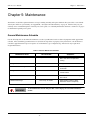
The PlateLoc needs little regular maintenance to keep it running smoothly. All repairs within the first year will be covered under
Velocity11’s initial one-year warranty. See Appendix B, “Velocity11’s Product Warranty” on page 51. After the first year, your
warranty can be extended through one of Velocity11’s service plans. See “Warranty Information and Service Contracts” on page 6
for information regarding service plans.
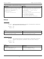
General Maintenance Schedule
Use the following table to determine the maintenance needs of your PlateLoc based on observed symptoms and the approximate
schedule. After determining your maintenance need, follow the steps below to properly clean your machine. The maintenance
schedule is approximated for expected “regular” use of the PlateLoc (up to 150 plates/day). Heavier use may require more
frequent maintenance.
Table 7: PlateLoc Maintenance Schedule
Maintenance Need
Clean the Hot Plate
Time Schedule
Inspect once a week.
Change the Seal Roll
--
Overall Machine Cleaning
Once a month
Change the NAFD2000 Filter
Varies
Inspect the Cutter
Lubricate Door Hinges
WARNING
Once a month
Once every six months
Symptoms
• Hot Plate Vacuum Error
• Plate sticks to the hot plate after
sealing
• Empty seal roll
• Dust and grime on machine exterior
and interior
• Insufficient Air Pressure Error
• Saturated Filter
• The seal material lacks a clean edge or
does not cut
• Door squeaks or moves slowly
• Door does not close completely
To avoid electrical shock and possible severe injury, do not remove PlateLoc
covers.
37
PlateLoc User Manual
Chapter 5: Maintenance
Cleaning the Hot Plate
WARNING
The hot plate remains EXTREMELY HOT during cleaning. Use a THICK rag
when cleaning to keep exposed skin safely away from the hot plate.
1) Remove the plate from the stage. Do not turn off the machine. The hot plate is easier to clean when kept hot.
2) The hot plate is located on the roof of the main sealing chamber. Using a thick, clean, dry rag, reach into the front opening
of the PlateLoc and carefully wipe off built up residue from the hot plate.
CAUTION
DO NOT use any type of metal object to clean the hot plate. Doing so will
damage the hot plate and adversely affect the seal quality.
Changing the Seal Roll
The seal roll only needs to be replaced when a roll empties. To replace a seal roll, follow the steps for removing the seal roll listed
below. After removing the empty seal roll, it is recommended to let the machine cool down to 30º C before following the
procedures outlined in “Mounting the Seal Roll” on page 11 and “Loading the Seal” on page 12.
Sometimes it is necessary to reload seal material without cooling down the machine. This may occurr if the PlateLoc displays an
error and instructs you to reload the seal material. The need also arises if the seal roll empties in the middle of an automated
process. To reload seal material without cooling down the machine, refer to “Reloading Seal Material into a Hot Machine” on
page 39.
38
PlateLoc User Manual
Chapter 5: Maintenance
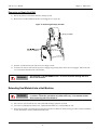
Removing an Empty Seal Roll
1) Detach any leftover seal material from the existing seal roll.
2) Remove the seal roll and hubs from the seal roll supports (see figure 14).
Figure 14: Removing the Empty Seal Roll
Empty Seal Roll
3) Unscrew one hub from the axle and remove the empty seal roll.
4) To remove the leftover seal material, open the seal gripper by pressing down on the lower seal gripper. Pull out the leftover seal material from the back of the machine.
WARNING
The Hot Plate is still EXTREMELY HOT! Do not insert hands through the front
door of the machine.
Reloading Seal Material into a Hot Machine
WARNING
The following procedure describes how to change the seal roll while the Hot Plate
is still hot. Follow this procedure only when necessary. Use extreme caution
when interacting with a hot PlateLoc.
1) Place the new seal roll onto the axle. The roll should fit snugly against the seal hub.
2) Screw the second hub back onto the axle. Tighten until the hubs are securely holding the roll.
3) Using scissors, make a clean straight cut across the end of the seal material, cutting off any part of the seal that is wrinkled
or torn. The PlateLoc will not work with wrinkled seal.
39
PlateLoc User Manual
Chapter 5: Maintenance
4) Place the seal roll with hubs and axle onto the seal roll supports. The roll should be placed so that the seal feeds from the
underside of the seal roll, as opposed to feeding from the top of the roll. The roll should fit easily into the two seal roll supports.
5) Feed the seal from the front of the roll toward the back along the top of the machine and down the back. Be sure to feed
the seal under the bar connecting the roll supports.
6) Feed the material into the seal roll slot directly above the lower seal gripper.
NOTE
If you have problems loading the seal, ensure that the edge entering the machine has not curled
down. Curl the edge up by hand to remove any downward curl.
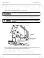
7) Figure 15 shows the path that the seal material takes through the machine. Look into the front opening of the machine.
You should see the seal material emerging from on top of the seal transfer plates (see figure 15).
WARNING
The surface above the main chamber is extremely hot. Do not insert hand into the
door of the machine. Adjust the position of the seal by moving it at the back of
the machine.
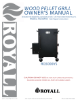
Figure 15: Feeding Seal Material into a Hot PlateLoc
Seal Material
Hot Plate
Lower Seal Gripper
Feed seal material into the
PlateLoc until the seal material
is flush with the edge of the
transfer plate.
Transfer Plate
8) Feed the seal until you see the front edge of the seal material is flush with the front edge of the seal transfer plate. Do not
insert the seal too far or it will stick to the hot plate. Ensure that the seal is centered.
9) Close the seal gripper by pushing the silver gripper release button under the gripper.
10) Roll any slack back up into the seal roll. Be careful not to move the seal from the correct position.
40
PlateLoc User Manual
Chapter 5: Maintenance
11) Run at least two manual cycles using an empty plate to ensure that the seal material is feeding correctly.
Overall Machine Cleaning
1) Set the temperature to 30 °C and wait for the machine to cool down.
NOTE
WARNING
The PlateLoc takes approximately one hour to cool down from its sealing temperature.
Ensure that the machine is cool before reaching inside to clean it. Reaching
inside the PlateLoc while it is still warm is extremely dangerous.
2) Turn off power to the machine.
3) Remove any scraps of seal material lying in the main sealing chamber.
4) Using a clean, dry cloth, remove any dirt or residue from the inside of the machine.
5) Using a clean, dry cloth, wipe down the machine exterior and the area surrounding the machine. It is also safe to use alcohol or standard glass/tile cleaner to clean the machine.
6) Turn power back on to the machine and reset the machine to its sealing temperature.
Changing the NAFD2000 Filter
The frequency with which the NAFD2000 filter needs to be changed depends on the particular air supply setup and overall
PlateLoc usage. An Insufficient Air Pressure Error is the initial signal that the filter may need to be changed. Upon receiving an
Insufficient Air Pressure Error, check the following conditions to determine if your filter needs to be changed:
•The PlateLoc gives an Insufficient Air Pressure Error when trying to run.
•The pressure gauge on the rear of the PlateLoc reads less than 90 psi.
•The pressure gauge at the air compressor reads 90 psi or greater.
If all the above conditions are met, the NAFD2000 filter may need to be changed. To verify that the problem is a dirty filter,
remove the filter from the air line running to the PlateLoc. If the pressure on the back of the PlateLoc reads correctly, the filter
needs to be replaced. If the pressure still reads incorrectly, call the Velocity11 Service Center.
The following steps describe how to change the NAFD2000 filter:
1) Turn off the PlateLoc.
2) Switch the pneumatic ON/OFF switch on the rear of the PlateLoc to the OFF position (toward the outside of the machine,
see figure 16).
41
PlateLoc User Manual
Chapter 5: Maintenance
Figure 16: PlateLoc Control Panel
Pneumatic Gauge
Pneumatic ON/OFF Switch
ON
OFF
(ON
OFF)
Air Input Port
3) Turn off the air supply and bleed off any excess air remaining in the line between the air compressor and the PlateLoc.
4) Hold the filter body and unscrew the filter bowl (see figure 17).
Figure 17: Unscrewing the NAFD2000 Filter Bowl
Filter Body
5) Check if the filter is saturated. A saturated filter is the final indication that the filter needs to be replaced.
6) Unscrew the dirty filter from the filter body and replace it with a new one (see figure 18).
Figure 18: Unscrewing the NAFD2000 Dirty Filter
Filter
7) Screw the filter bowl back on the filter body.
8) Turn on the air supply and ensure that it reads the proper pressure.
9) Switch the pneumatic ON/OFF swtich on the back of the PlateLoc to the ON position. Ensure that the pressure gauge on
the back of the machine reads about 90 psi.
WARNING
When you turn on the air supply to the PlateLoc, the door will open and the stage
will extend. Keep the area in front of the PlateLoc clear.
42
PlateLoc User Manual
Chapter 5: Maintenance
Inspecting the Cutter
1) Set the temperature to 30 °C and wait for the machine to cool down.
NOTE
WARNING
The PlateLoc takes approximately one hour to cool down from its sealing temperature.
Ensure that the machine is cool before reaching inside to clean it. Reaching
inside the PlateLoc while it is still warm is extremely dangerous.
2) Run the machine without a plate and with the temperature set to 30 °C.
3) Remove the piece of seal material and ensure that it has a nice, clean edge.
4) Repeat the process three or four times.
5) If you repeatedly notice the seal material has a frayed or poorly cut edge, the cutter on your PlateLoc may have dulled or
may have shifted to an incorrect position. Please contact Velocity 11’s Service Center at (650) 846-6500.
Lubricating the Door Hinges
1) Turn off power to the machine.
2) Switch the pneumatic ON/OFF switch on the back of the machine to OFF (toward the outside of the machine).
3) Remove the plate, plate support insert, and plate locator from the stage.
4) With the stage extended, carefully apply one drop of a standard lubricant (Tri-Flow, 3-in-1) to the side of the door hinges
located just on the inside of the main chamber (see figure 19). Be sure to apply the lubricant to the side of the door hinge
and allow the lubricant to run down into the door hinge axle (the rod and spring connecting the two door hinges).
Figure 19: Lubricating the Door Hinges
Door Hinges
Stage
Door
5) Open and close the door repeatedly by hand to help spread the lubricant.
6) Wipe off excess lubricant from the machine interior.
43
PlateLoc User Manual
Chapter 5: Maintenance
44
PlateLoc User Manual
Chapter 6: Troubleshooting
Chapter 6: Troubleshooting
The following troubleshooting guide offers a series of steps to follow to correct problems with your PlateLoc as quickly as
possible. If problems persist or if you have any questions regarding the troubleshooting procedure, please contact the Velocity11
Service Center.
WARNING
To avoid electrical shock and possible severe injury, do not remove PlateLoc
covers. Refer servicing to qualified Velocity11 personnel only.
The Velocity11 Service Center is always available to assist you with any of your PlateLoc needs. Please feel free to contact the
Velocity11 Service Center at any point in the troubleshooting process. For information regarding your PlateLoc service plans,
consult “Velocity11’s Product Warranty” on page 51.
NOTE
Velocity11’s Service Center can be reached at (650) 846-6500.
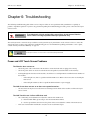
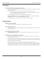
Power and LCD Touch Screen Problems
The PlateLoc does not turn on.
• Check the power cable on the back of the machine to ensure that both ends are plugged in correctly.
•
Check the power switch to ensure it is switched to the ON position (toward the inside of the machine).
•
Looking through the front door of the machine, check if there is a red light turned on within the main chamber of
the machine.
-
If the red light is on, there is a problem with the LCD screen. Refer to the next section on checking the
LCD screen.
-
If the red light is NOT on, there is a problem with the PlateLoc’s power supply.
The LCD Screen does not turn on or does not respond to touches.
• The Touch Screen may have been disconnected or damaged on the inside of the machine. Call the Velocity11
Service Center.
The LCD Touch Screen is dim or difficult to read.
• The contrast may need adjustment. To adjust the contrast of the LCD screen:
1) From the Main Menu, press Setup to enter the Set Parameters Menu.
2) Use the up and down arrows next to the picture of the sun to adjust the contrast of the LCD Screen.
•
If the screen remains dim or difficult to read, the screen needs internal repair.
45
PlateLoc User Manual
Chapter 6: Troubleshooting
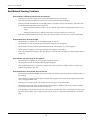
Air Problems
“Insufficient Air Pressure” Error Message on LCD screen.
• Check the pneumatic ON/OFF switch on the rear of the PlateLoc. Ensure that it is in the ON position (towards
the inside of the machine).
•
Check the air pressure gauge on the rear of the PlateLoc. It should read approximately 90 psi.
-
If it reads above 80 psi and the error message persists, there is a problem with the PlateLoc’s air pressure sensor. Contact the Velocity11 Service Center.
•
Check the air supply. Ensure that it is turned on and supplying enough pressure.
•
Inspect the NAFD2000 air filter to see if it needs replacement. For instructions on removing and changing the
NAFD2000 air filter refer to “Changing the NAFD2000 Filter” on page 41.
•
If the problem persists, the pressure regulator within the PlateLoc may have a problem.
Sealing Problems
The plate sticks to the hot plate.
• There may be residue on the hot plate. Refer to “Cleaning the Hot Plate” on page 38.
The seal material does not cut.
• The cutter blade may need to be sharpened or adjusted. Refer to “Inspecting the Cutter” on page 43 to determine
the problem with the cutter.
The seal edge is tattered or cut unevenly.
• The cutter blade may need to be sharpened or readjusted. Refer to “Inspecting the Cutter” on page 47 to determine the problem with the cutter.
The plate does not seal completely or seals unevenly.
• Check that you are using the correct support insert. See “Selecting a Plate Locator Insert” on page 17 to determine the proper insert for your plate.
•
Refer to the standard seal times and temperatures listed in Table 2 and ensure your setup corresponds to the table.
•
In the Set Parameters menu, increase the seal time. Different plates demand different seal times and temperatures
than those suggested by the seal manufacturer.
•
Inspect the top surface of the plate to ensure it is flat. Warped or crooked plates may seal poorly.
•
If the plate continues to seal poorly, examine the plate carefully. Velocity11’s PlateLoc is specifically designed
to seal microplates whose well edges, “chimneys”, are raised above the surface of the plate. Plates with chimneys
lower than the surface of the plate may not seal well or may require a longer seal time and higher temperature.
46
PlateLoc User Manual
Chapter 6: Troubleshooting
Seal Material Feeding Problems
Seal material is difficult to remove from the machine.
• Turn the power off. The transfer plates will automatically release the seal material.
•
If the seal material is still difficult to remove, the seal may be stuck inside the PlateLoc.
•
Turn the pneumatic ON/OFF switch to the OFF position (towards the outside of the machine). This will release
the internal mechanisms from their fixed positions.
•
-
If the seal material is NOT piercable seal, try to pull the seal material out using significant force if necessary.
-
If using piercable seal, try to pull the seal material out being careful not to tear the seal.
If the seal material remains stuck or tears, contact the Velocity11 Service Center to have it removed internally.
Seal material does not feed straight.
• Check that the seal roll hubs are screwed tightly against the seal roll.
•
Check that the seal roll sits straight and is seated fully within the seal roll supports.
•
Check that the seal material is being fed underneath the bar connecting the two seal roll supports.
•
Check that the seal gripper is closed by pressing the silver gripper release button.
•
If the seal feeding does not improve after 10 to 20 cycles, check the cutter blade. Refer to “Inspecting the Cutter”
on page 43.
Seal roll does not spin easily in roll supports.
• Check that the seal roll hubs are screwed tightly against the seal roll.
•
Check that the seal roll sits straight within the seal roll supports.
•
If the problem persists, the seal roll may be damaged. If a spare seal roll is available, check to see if the same
problem exists with the spare roll.
Seal material does not feed into the seal roll slot.
• Check that the pneumatic ON/OFF switch on the PlateLoc is switched to the ON position (towards the inside of
the machine).
•
Check that the seal gripper is lowered by pressing the silver gripper release button and then pushing down on the
lower seal gripper until it clicks.
•
Turn the power off and on again. The machine powers on ready to accept seal material.
•
Check that the front edge of the seal material has not curled down or wrinkled. Cut off any curled or wrinkled
seal and try to reinsert the material into the seal roll slot.
•
Look through the seal roll slot from the rear of the machine. You should be able to see through to the front opening of the machine. If the view is obstructed, there may be scraps of seal material obstructing the seal material
path.
47
PlateLoc User Manual
Chapter 6: Troubleshooting
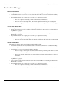
PlateLoc Error Messages
Hot Plate Vacuum Error
The hot plate did not detect that a full piece of seal material was ready to be applied to the plate.
•
Look inside the machine to see if there is a scrap of seal material. If there is a scrap of material in the machine,
remove it.
•
Try running the PlateLoc with a spare plate to see if the cycle completes successfully.
-
If the cycle completes successfully, continue with normal use of the PlateLoc.
-
If the same error repeats multiple times, there may be a problem with the hot plate vacuum system.
-
If a new error appears, find the error in the list of PlateLoc error messages listed on the following pages.
Transfer Plate Vacuum Error
The transfer plate did not detect the seal material in a correct position for feeding.
•
Remove the seal from the rear of the machine. If the material is difficult to remove, refer to “Seal Material Feeding Problems” on page 47.
•
Cut off any tattered edges and reload the seal material into the machine. Refer to “Reloading Seal Material into a
Hot Machine” on page 39.
•
Try running the PlateLoc with a spare plate to see if the cycle completes successfully.
-
If the cycle completes successfully, continue with normal use of the PlateLoc.
-
If the same error repeats multiple times, there may be a problem with the transfer plate vacuum system.
Actuator Timeout Error
The transfer plate did not complete one of its movements in the allotted time.
•
Check if the seal roll spins with only moderate resistance in the roll supports. Refer to “Seal Material Feeding
Problems” on page 47.
•
Check if there is a cut piece of seal material inside the machine.
-
If there is a scrap, the transfer plate was obstructed from returning to its home position in the rear of the
machine. Remove the scrap piece of seal material.
-
If there is no scrap, the transfer plate was obstructed from reaching its transfer position at the front of
the machine.
•
Remove the seal from the rear of the machine. If the material is difficult to remove, refer to “Seal Material Feeding Problems” on page 47.
•
Cut off any tattered edges and reload the seal material into the machine. Refer to “Reloading Seal Material into a
Hot Machine” on page 39.
•
Try running the PlateLoc with a spare plate to see if the cycle completes successfully.
-
If the cycle completes successfully, continue with normal use of the PlateLoc.
-
If the same error repeats multiple times, there may be a problem with the seal material feed mechanism.
48
PlateLoc User Manual
Chapter 6: Troubleshooting
Cycle Stopped Manually Warning
The user aborted the sealing cycle by pressing the Stop button.
•
Try running the PlateLoc with a spare plate to see if the cycle completes successfully.
-
If the cycle completes successfully, continue with normal use of the PlateLoc.
-
If a new error appears, find the error in the list of PlateLoc error messages.
Door Close Error
The door was not closed for the entire seal cycle.
•
Turn the pneumatic ON/OFF switch on the back of the machine to the OFF position (towards the outside of the
machine).
•
Push the stage into the machine while holding the door open.
•
Gently open and close the door to ensure nothing is blocking the door or the door hinges.
-
If there is nothing obstructing the door but it will not close fully, call the Velocity11 Service Center.
-
If the door closes fully and the error message persists, the door sensor may be malfunctioning.
NOTE
If the door closes fully, turn the pneumatic ON/OFF switch to the ON position and the PlateLoc
stage will push the door open.
No Plate in Holder Error
• Check that the plate was positioned properly in the plate locator.
•
Run the PlateLoc again. If the error repeats, there may be a problem with the plate sensor.
Temperature Sensor Deviation Error
The PlateLoc encountered a problem reading the temperature of the hot plate. The heaters automatically turned off
and the machine will start to cool down.
•
Restart the PlateLoc.
•
If the error persists, call the Velocity11 Service Center.
Overheat Error
The PlateLoc’s temperature control system has malfunctioned.
•
Monitor the temperature of the machine displayed on the LCD screen. If the temperature continues to rise, power
down the machine and unplug the machine from the outlet.
•
Contact the Velocity11 Service Center.
Keystone Error or Memory Access Error
PlateLoc encountered problems accessing system memory.
•
The PlateLoc memory may have been corrupted. Call the Velocity11 Service Center to verify that the PlateLoc
settings are still correct.
49
PlateLoc User Manual
Chapter 6: Troubleshooting
Serial Communications Error
The serial communications input buffer has been overloaded.
•
Ensure that the serial command input is correct.
•
If the error persists, contact the Velocity11 Service Center.
50
PlateLoc User Manual
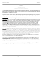
Appendix A
Appendix A
Velocity11’s Product Warranty
Velocity11, a California corporation with its principal place of business at 435 Acacia St., Palo Alto, California 94306
("Velocity11") is the obligor of this service contract (“Contract”).
This Contract sets forth the terms and conditions under which Velocity11 will provide Support Services (as defined below) for its
Products covered under the Product Warranty guidelines.
1.
DEFINITIONS
1.1
Support Services" means the support and/or services that are available from Velocity11, as further described in Exhibit A,
may be amended from time to time.
2.
COVERAGE
Velocity11 will provide the Support Services set forth in Exhibit A and pursuant to the terms and conditions of this
Contract for one year after the purchase date of the product.
Additionally, the Customer has the option to purchase an enhanced “Platinum” Support Services contract. Terms,
conditions and rates of enhanced coverage are set forth in Exhibit B of this Contract.
Within 30 days prior to the expiration date of the Product Warranty or Support Services contract, Velocity11 will offer the
Customer the option of purchasing additional coverage based on the current Support Services rates at that time.
3.
SUPPORT SERVICES
3.1
In order for Customer to receive the Support Services described in Exhibit A, Customer must:
(a) Initiate a service request by contacting Velocity 11 at (650) 846-6500.
(b) Provide the serial number of the Product, a description of the problem and the current version of the control software.
(c) Provide a detailed description of the type of error, a description the specific error message and when it occurs, the
activity or use of the Product when the error occurred and remedial measures taken by the Customer to correct the
error.
(d) Follow procedures and recommendations provided by the Velocity11 technician in an effort to correct problems via
telephone. (VELOCITY11 WILL NOT DISPATCH A SERVICE TECHNICIAN TO PERFORM ON-SITE
REPAIRS UNTIL THE TELEPHONE-BASED TROUBLESHOOTING PROCESS HAS BEEN EXHAUSTED)
(e) Subject to Customer's applicable security requirements, provide Velocity11 with access to and use of all information
and Product facilities, including working space, electricity and a local telephone line, necessary for Velocity11 to
provide timely Support Services pursuant to this Contract.
(f) To the best of its abilities, read, comprehend and follow operating instructions and procedures as specified in, but not
limited to, Velocity11 documentation and other correspondence related to the products.
3.2
Velocity11 shall have no obligation to support:
51
PlateLoc User Manual
Appendix A
(a) altered or damaged Products;
(b) any version of the Products other than the current version of the product, unless otherwise covered under an existing
service contract or agreement;
(c) any Product with software that has been modified or is out-of -date, without the written approval and authorization of
Velocity11;
(d) Product problems caused by Customer's negligence; Customer abuse or misapplication, including but not limited to
use of incorrect voltages, use of incorrect fuses, use of incompatible devices or accessories and improper or
insufficient ventilation; use of Product other than as specified in the user manual; or other causes beyond the
reasonable control of Velocity11, including but not limited to an act of God such as lightning, floods, tornado or
earthquake;
(e) Products installed on any hardware, operating Product version or network environment that is not supported by
Velocity11;
(f) Products sold or transferred by the Customer to another entity.
4.
FEE SCHEDULE
Customer shall pay the annual fees for Support Services for the initial term of this Contract within thirty (30) days of the
Effective Date. Thereafter, (unless Support Services are not renewed) Customer shall pay annual Support Services within
30 days of the commencement of the then-current term for such Support Services.
5.
TERM AND TERMINATION
5.1
The initial term of this Contract is one (1) year from the Effective Date of this Contract unless earlier terminated in
accordance with this Contract. The Customer will be notified within thirty (30) days prior to the expiration date of the
Product Warranty or Support Services contract and will have the option of purchasing additional coverage based on the
current Support Services rates at that time.
5.2
Velocity11 may suspend or terminate Support Services if Customer fails to timely pay Support Service fees as provided in
this Contract. Velocity11 may also terminate Support Services if Customer breaches any provision of this Contract and
such breach is not remedied within thirty (30) days after Customer receives written notice of the breach. Velocity11 shall
also have the right not to renew this Contract with respect to any Product by providing written notice of such election at
least ninety (90) days prior to the termination of Support Services for such Product, provided that Velocity11 no longer
generally provides Support Services for such Licensed Product, or no longer provides the specific Support Services
previously offered.
5.3
Customer may terminate this Contract if Velocity11 materially breaches its obligations under this Contract. If Customer
terminates this Contract due to a material breach on the part of Velocity11, Velocity11 will refund the support fees for the
then current term paid by Customer under the Contract, from the date of termination prorated to the end of the then current
term.
52
PlateLoc User Manual
6.
Appendix A
REINSTATEMENT OR RENEWAL OF SUPPORT SERVICES
In the event Customer fails to timely renew Support Services under this Contract, Support Services shall be discontinued
at the end of the then-current term. If Support Services are terminated for any reason, at Velocity11’s sole option,
Customer may be permitted to reinstate or renew Support Services by paying Velocity11 applicable Support Services
fees.
7.
LIMITED WARRANTY
Velocity11 warrants that Support Services will be performed with the same degree of skill and professionalism as is
demonstrated by like professionals performing services of a similar nature.
8.
LIMITATION OF LIABILITY
8.1
Direct Damages. VELOCITY11’S SOLE LIABILITY AND CUSTOMER'S EXCLUSIVE REMEDY FOR DAMAGES
WITH RESPECT TO THE SUPPORT SERVICES UNDER ANY CONTRACT, TORT (INCLUDING NEGLIGENCE),
STRICT LIABILITY OR OTHER THEORY, SHALL BE LIMITED TO THE AMOUNT PAID BY CUSTOMER FOR
THE SUPPORT SERVICES.
8.2
Consequential Damages. UNDER NO CIRCUMSTANCES, INCLUDING NEGLIGENCE, SHALL VELOCITY11 BE
LIABLE FOR ANY SPECIAL, INCIDENTAL OR CONSEQUENTIAL DAMAGES INCLUDING, WITHOUT
LIMITATION, DAMAGES FOR LOST PROFITS, LOSS OF DATA, OR COSTS OF PROCUREMENT OF
SUBSTITUTE GOODS OR SERVICES, ARISING IN ANY WAY OUT OF THIS CONTRACT OR THE USE OF THE
LICENSED PRODUCT, DESIGN TECHNIQUES AND DOCUMENTATION.
9.
ENTIRE CONTRACT
This Contract and the attached Exhibit constitute the entire Contract between the parties regarding Support Services and
supersede all previous Contracts or representations, oral or written, regarding the subject matter. This Contract may not
be modified or amended except in a writing signed by a duly authorized representative of each party. Both parties
acknowledge having read the terms and conditions set forth in this Contract and Exhibits attached hereto, understand all
terms and conditions, and agree to be bound thereby.
53
PlateLoc User Manual
Appendix A
EXHIBIT A
SUPPORT SERVICES
VELOCITY11’S STANDARD WARRANTY
The Standard Warranty, effective for one full year upon purchase date, covers all parts and labor costs necessary to repair your
covered product due to all functional part failures as reasonably considered under this contract. If the technician cannot correct the
Product problem over the telephone at the initiation of a service request, then the technician will follow the procedures outlined for
the Support Services, described in this Agreement.
Non-shippable Products: a service technician will be dispatched the next business day, excluding holidays, to repair the Product(s).
Regular holidays shall include New Year's Day, Memorial Day, Independence Day, Labor Day, Thanksgiving Day, the day after
Thanksgiving, and Christmas Day, unless Velocity11 determines otherwise and notifies Customer with 30-day advance notice.
Shippable Products: Product(s) must be shipped directly to Velocity11 to be repaired.
On-Site Service. On-site service is available for Customer Products within the United States. The technician will need to have the
full address of Customer Products’ location. A service technician will be dispatched to Customer’s location to service Customer’s
Product. The Services provided under this Agreement are repair services that are necessary because of any defect that exists or
occurs in materials or workmanship in the Products or in any Product component covered by this Agreement. The Standard
Warranty does not include preventive maintenance, installation, deinstallation, relocation services or operating supplies. If
Customer or Customer’s authorized representative are not at the location when the service technician arrives, Velocity11 will no
longer be obligated to provide services under this Agreement for the Product that requires service on such visit. The service
technician will leave a notice with the time of arrival as proof of arrival. Consequently, you may be charged an additional fee for a
second service call to repair your instruments.
Service Area. This Agreement applies only to Products located in the United States. In addition, Velocity11 may invoice Customer
an additional charge for service in certain remote areas of the United States. Velocity11 will notify Customer if Customer Products
are in an area where Velocity11 cannot offer on-site service. If Customer relocates its Product(s) to a geographic location in which
the Standard Warranty service is not available, Customer may incur an additional charge to maintain the same categories of service
coverage at the new location. If Customer chooses not to pay such additional charge, Customer service may be automatically
changed to categories of service that are available in such new location with no refund available.
For purposes of the Gold Service, all references to time will mean the Customer’s local time. References to the United States
include the continental United States, Alaska, Hawaii and Puerto Rico.
Whole Unit Replacement. If the telephone technician determines that the defective unit is one that is easily disconnected and
reconnected, or if the technician determines that Customer Product is one that should be replaced as a whole unit, Velocity11
reserves the right to request that the defective unit be shipped to Velocity11 for repairs. Under the Standard Warranty, Velocity11
will repair the unit, and ship it back to Customer.
Parts Ownership. All service parts removed from Customer Product(s) become Velocity11 property. Customer must pay the
current retail price(s) for any service parts removed from Customer Product(s) and retained by Customer.
54
PlateLoc User Manual
Appendix A
EXHIBIT B
OPTIONAL SUPPORT SERVICES
Platinum Service Plan
The Platinum Service Plan is available to each customer at an additional cost.
Under the Platinum Service Plan the Customer is guaranteed a four-hour response time for all repair service calls. When required,
a Service Technician will be dispatched the same day the request was initiated, 365 days of the years.
For shippable items, Velocity11 will ship out a replacement product within twenty-four hours. The Customer will be responsible
for shipping the damaged product back to Velocity11 in three working days after receiving the replacement product from
Velocity11.
The Customer may upgrade to this plan during the first year of service. Please contact your Velocity11 representative for more
details.
55
PlateLoc User Manual
Appendix A
56
PlateLoc User Manual
Index
Index
A
I
ActiveX 23
Diagnostics Screen 32
Error Strings 29
Events 34
Install 23
Methods 31
Properties 24
SCodes 34
advisories 6
air 8
filter 8
input port 9
pneumatic ON/OFF switch 10
problems 46
quick connect 7, 9
requirements 5
installation 8
C
P
U
plate locator 17
pneumatic gauge 10
polyurethane tubing 9
power
120VAC 10
cable 10
problems 45
switch 10
UL 6
unpacking 7
CE 6
certification 6
chimney 17, 21
cleaning 41
cold cycle 15
control panel
air connections 8
covers 45
cutter
inspecting the 43
D
door
close error 49
door hinges 37, 43
E
error messages 48
F
filter 8
arrow 9
changing the 41
G
gripper release button 13
H
hot plate 39
cleaning 38
plate sticks to 46
safety 38
vacuum error 48
L
LCD touch screen 14, 18
problems 45
lower 13
lubricate 37, 43
M
main chamber 40, 43
Main Menu 14
maintenance 37
schedule 37
manual sealing 20
memory
errors 49
R
regular use 37
S
seal gripper 12
seal material 11
feeding problems 47
loading 12
seal quality 21
seal roll
axle 11
changing 38
hubs 11
mounting 11
slot 13
supports 11
Seal Temp 19
seal transfer plate 40
vacuum error 48
seal transfer plates 13
sealing
problems 46
serial communications 10
error 50
port 10
57
service 6
phone number 45
Service Center 5
Support Services 51
Service button 19
Set Parameters Menu 14
Setup button 19
State Codes 27
Status 15
support insert 17
system requirements 5
T
temperature
errors 49
troubleshooting 45
tubing 9
V
vacuum error 48
W
warranty 51
website 5
wells 17