1
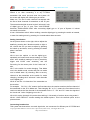
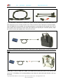
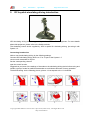
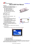
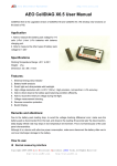
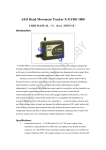
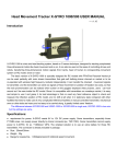
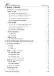
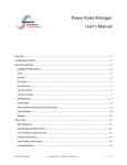
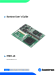
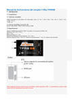
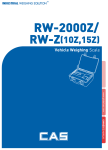
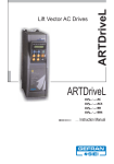
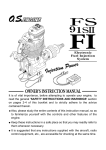
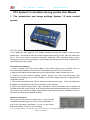
Aero
Electronics
Operations
http://www.aeorc.com
FPV System1.5 simulation driving system User Manual
1. The introduction and usage settings System 1.5 main control
system
AEO FPV System 1.5 is the most powerful FPV RC core processing system.
It has digital port and graphical LCD display. Breaking through the tradition, using the high
performance processors to reach the channel mapping and mixing function. Also can achieve the
aim of FPV control without advanced transmitter. Meantime, AEO simulating driving system
component can give user a real feeling of Joystick flight and steering wheel driving. Following is the
user introduction of this system.
The function introduction:
1. Using it together with AEO special digital version head tracking gyro: X-GYRO 1500. It’s
convenient to set parameters and control the head tracking movement by X-GYRO1500.
2. Support AEO special control peripheral such as flying joystick, steering wheel and so on.
3. Powerful and free channel mapping function. Support four input devices(including main
transmitter and digital gyro) at a time, available to cross the mapped channels to experience the
cooperation control.
4. Two control combination ways. Able to switch the control device quickly. Be free to experience
the different control device or hand the control right to other instantly.
5. PPM coach signal mixing function, high performance, without time delay. Able to support all
FUTABA device with coach function. Even though without advanced transmitter, able to experience
FPV driving. This system can support all device with PPM signal output port. Available to use it on
JR device with AEO special adapter modules.
Interface introduction:
This system has four ports, from right to left: “A” port is special
for digital head tracking gyro; “B” port for main transmitter; “C”
port for the first deputy transmitter; “D” port for the second
deputy transmitter. “C” and “D” can exchange.
Copyright 2005-2009 Aero Electronics Operations(AEO Tech) , All Rights Reserved
http://www.aeoRC.cn
Aero
Electronics
Operations
http://www.aeorc.com
System 1.5 uses FUTABA coach port to supply power.
Switch it on after connecting it to any FUTABA
transmitter with coach port and enter into system. On
the screen will display the following as per shown.
Mode one, The first to sixth channels correspond with
the first to sixth channels of transmitter on the “B” port.
The seventh and eighth channel to the X-axis and Y-axis
of digital gyro on the “A” port. That “LINK ERROR”
becomes “WWW.AEORC.COM” after connecting digital gyro to “A” port of System 1.5 shows
successful connection.
It has a 5 directions switch. When working, reset the digital gyro by pressing the switch to inwards,
or enter into setting menu by pressing it to inwards about three seconds.
Setting introduction:
As the picture shown on the right, able to adjust the
details by pressing the 5 directions switch to right or
left, choose the one you want to adjust by pressing
the switch up and down, save by pressing it inwards
about 3 seconds.
Details:
NO.1-6 are the options to set the digital gyro,
separately as forward and reverse setting of X axis
and Y axis, sensitivity setting of X and Y (sensitivity
bigger and GYRO more sensitive), and the
fine-tuning for the center point of the X axis and Y
axis.
NO.7 is the switch for mode changing. That Mode
one is the default mode, means that just use mode
one in default state. By choosing, able to set any
channel on the transmitter as the switch for mode
changing, including the X axis and Y axis channels
on the digital gyro.
NO.8-15 are the 1-8 channels of the transmitter on
the receiver.
For example, ”M1 CH1 = B1” means, the first channel on the receiver matches the first channel of
the transmitter on the “B” in Mode one. That changing “B1” to “C1”, means, the first channel on the
receiver matches the first channel of the transmitter on the “C”. “AX” and “AY” mean the signals of
the X axis and Y axis of digital gyro on the “A”
NO.16-23 are the channels of input device matching 1-8 channels of receiver when using mode 2.
NO.24 “LOAD DEFAVLT” means reading the default options. This is the default option as the
picture shown.
Connecting introduction:
This system has three wires: one main signal wire, two connectors for different port of FUTABA and
Copyright 2005-2009 Aero Electronics Operations(AEO Tech) , All Rights Reserved
http://www.aeoRC.cn
Aero
Electronics
Operations
http://www.aeorc.com
one connectors for supplying power.
If you transmitter is lower than FUTABA 12FG, please use the square port with black tube (Such as
FF9, 6EX and so on) or round port (T9Z, FF7, FF8) to connect to the coach port on the transmitter.
Take FUTABA 6EX as a example. As the following picture, connecting the main signal wire to “B” of
main system and connecting it to the coach port of 6EX by the square port connector (black). Open
the coach function and supply power, then you can use it.
If using FUTABA advanced device such as T12MZ and T14MZ, please use the connector with blue
tube.
U
Additionally, If using T12MZ and T14MZ, you should add a power port (refer to the picture) and
connect a 7-12V battery (7.4V recommended) on the other port. Open the coach function, then you
can use it.
Copyright 2005-2009 Aero Electronics Operations(AEO Tech) , All Rights Reserved
http://www.aeoRC.cn
Aero
2.
Electronics
Operations
http://www.aeorc.com
RC Joystick simulating driving introduction
AEO simulating driving device is upgraded by us based on the Saitek equipment. For more details
about this equipment, please refer to the Saitek web site.
The simulating control device supplied by AEO is special for simulating driving, just using it with
System 1.5.
Connecting introduction:
Able to use the simulating driving by the following settings:
Connect AEO simulating driving device to “C”or “D”port of the System 1.5
connect main transmitter to “B”port
Set the corresponding channel
open the coach function
Suggest that you know of the settings of channels on the simulating driving device before using and
remain a group of mode for traditional transmitter to avoid losses because of wrong operation.
The default setting: As the following picture, picture 1-8 correspond to the 1-8 channels.
Copyright 2005-2009 Aero Electronics Operations(AEO Tech) , All Rights Reserved
http://www.aeoRC.cn
Aero
Electronics
Operations
http://www.aeorc.com
The channel setting introduction:
If you need to change the default setting, please refer to the following steps:
1. Please connect main transmitter, System 1.5 and simulating driving device correctly. Ensure that
those can work.
2.Choose a mode randomly in the setting menu of System 1.5, such as mode one.
3.Set channel mapping. The mapping function of System 1.5: Connect the device output channel
on the “A”, “B”,“C”and“D” input port to CH1-CH8 signal output channel, the signal will be sent by the
transmitter to control the servo on the CH1-CH8 of receiver.
4.Don’t map one input channel to more than one channel to avoid wrong operation.
5.If the mapped channel is the port without device, there will be interfering signal. Please ensure
that the mapped channel connect the device correctly after setting completed.
Note: Some FUTABA also can supply power to System 1.5 when OFF, so please pull out the port
from coach port when not using to avoid battery damage.
instance introduction:
The default throttle of RC Joystick is the third channel. Need to modify it to the second channel. To
avoid transmitters mixing, need to change the second channel function to the third. Please refer to
the following steps:
1. Connect all devices and ensure it work well. For introducing, connect simulating control device to
“C” port.
2. Set the seventh option ”MODE SW” to “MOD 1” in the System 1.5 menu. By default, MODE 1
turned on, Mode 2unavailable. (If you need to set it to mode 2, please set a switch for mode
changing and switch to mode 2 when using)
3. Modify the value of “M1 CH2” to “C3” and “M1 CH3” to “C2”. The second channel of receiver is
controlled by the third channel of simulating device on the “C” port, and The third channel of
receiver controlled by the second channel of simulating device.
4 Channel separation: Connect another device to “C” or “D” and set M1 CH1=C1(D1)and M1 CH3
= B3. Then the mani transmitter on the “B” port controls throttle, and the device on the “C” port
controls aileron.
Copyright 2005-2009 Aero Electronics Operations(AEO Tech) , All Rights Reserved
http://www.aeoRC.cn