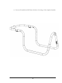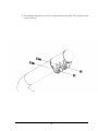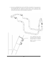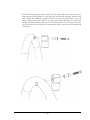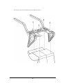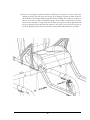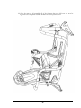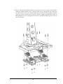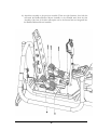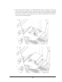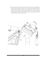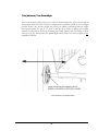
1
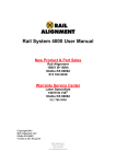
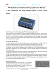
FLIGHT MOTION SIMULATORS INC. Dreamflyer FMS df X-2 Model No. FMS df X-2 Serial No. __________________ Serial number location Questions? If you have questions, or if there are missing parts, we will guarantee complete satisfaction through direct assistance from our factory. The trained staff on our customer hot line will provide immediate assistance free of charge to you. Customer Hot Line: 1-877-435-9746 Mon. – Fri. 9:00 a.m. – 4:00 p.m. PST [email protected] CAUTION Read all precautions and instructions in this manual before assembling or using this equipment. Keep this manual for future reference. User Manual REL-E-03 FLIGHT MOTION SIMULATORS FMS df X-2 User’s Manual FMS Flight Motion Simulators Inc. Unit 4-230 Loughheed Road, Kelowna, BC, Canada V1V2M1 Phone 250 765-8359 • Toll Free 1 877 435-9746 [email protected] Saitek is a separate legal entity and does not Endorse or recommend Dreamflyer Flight Motion Simulator In any way shape or form. 1 Table of Contents Important Precautions............................................. 3 Before You Begin ................................................... 4 Assembly ................................................................ 5 Initial Set Up ......................................................... 25 Software Notes ................................................................... 25 Trim (balance) Your Dreamflyer.......................................... 27 Maintenance and Troubleshooting ........................ 28 How to Order Replacement Parts ......................... 28 Limited Warranty .................................................. 28 Statement of Warranty ........................................................ 28 Warranty ............................................................................. 28 Warranty Service ................................................................ 29 Extent of the Warranty ........................................................ 29 Limitations of the Liability .................................................... 30 Additional Rights ................................................................. 30 Thank You ............................................................ 30 2 Important Precautions To reduce the risk of serious injury or damage to the flight motion simulator, please read the following important precautions before using your Dreamflyer motion simulator. Read all instructions in this manual before using the flight motion simulator. Great care must be taken when climbing on to or off of the flight motion simulator. The machine can and may move at any time in any direction causing a fall or possible injury. Do not stand on rudder pedals when mounting the flight motion simulator. Remove feet from rudder pedals before trying to shift your weight or stand up. It is the responsibility of the original owner to ensure that all users of the flight motion simulator are adequately informed of all precautions. Place the flight motion simulator on a level surface. Keep the simulator indoors and away from moisture and dust. Inspect and properly tighten all parts on a regular basis. Replace any worn parts immediately. Keep children under 4 and pets away from the flight motion simulator at ALL times. Ensure children under 18 are supervised at ALL times when using or around the flight motion simulator. The flight motion simulator should not be used by persons weighing more than 250 Lbs, by pregnant women or people using medications... If you feel dizziness or illness while using the flight motion simulator, stop immediately and contact your physician. Do not lean on the flight motion simulator at any time as it may move causing a fall or injury. Ensure that the main monitor is attached using ONLY the screws provided by Flight Motion Simulators Inc. These screws are slightly longer and will ensure a safe mounting of the monitor. Please ensure that any person using your flight motion simulator is aware of all the precautions on this page. 3 Before You Begin Congratulations for selecting the Dreamflyer Flight Motion Simulator. The simulator has been designed to ensure that you have many years of enjoyment from your flight motion simulator. If you have questions after reading this manual, call our customer service department toll-free at 1-877-435-9746 Monday thru Friday 9:00 AM to 4:00 PM Pacific time (excluding holidays). To help us assist you please note the serial # before calling. We can also be reached by email at [email protected] Before reading further, please familiarize yourself with the parts and terms shown in the diagram below. 4 Assembly Assembly requires two healthy and capable persons to complete successfully. Place all parts of the flight motion simulator in a cleared area and remove all packing materials. All tools for assembly are included within the packaging. Before proceeding, read through all the assembly steps and identify the fasteners that will be used at each step. It may help to lay these out in groups in the order of the assembly steps to ensure you have correctly identified the fasteners before you begin assembly. Not all fasteners and tools shown here. 5 1) Assemble both Frame End Supports as shown below. Adjust Screw Feet to middle of their adjustment. Slide both Frame End Supports onto Main Frame. Slide Frame End Supports to the ground ensuring to be careful so as not to scratch the finish on the Main Frame. Align both Frame End Supports perpendicular to Main Frame and tighten two clamp screws on each end securely. Adjust feet to ensure frame does not rock on ground. 6 2) Attach Joystick Mounting Plate and Joystick Controller to Main Frame as shown below. Ensure arrow on Joystick Mounting Plate is pointing forward as shown below. 7 3) Attach Joystick Assembly to Main Frame as shown below. 8 Main Frame Assembly should look like picture below when completed. 9 4) Next we will assemble the Roll Frame. See below for an image of the completed assembly. 10 5) Install clamp bolts and nuts at all four clamp locations on assembly. Do not tighten at this point. See below. 11 6) Insert the two Mid Roll Tubes into Front Roll Tube Assembly first. Leave screws loose. Next slide Rear Roll Tube Assembly onto exposed ends of the two Mid Roll Tubes. Ensure Mid Roll Tubes are completely inserted into clamp sections of mating tubes, both front and rear tubes, before securely fastening the clamp screws. Top of Mid Roll Tube should be visible beyond second clamp through clamp slot as indicated below by arrow at all four clamp locations. 12 7) Roll Frame Pivot Bearings will be installed next. The procedure is the same for both the front and rear Pivot Bearings. Use the large bolts and the brass bushings. Ensure notch end of black Pivot Bearing is against the hole in the tube as shown below in second picture. Tighten these bolts until they no longer turn. Ensure Bearing Pivot spins freely around the installed bushing and bolt. If Pivot Bearing does not move freely, un-screw the bolt and ensure that there is no foreign matter in any of the holes. Re-assemble and check again. 13 8) Now we will hang the completed Roll Frame within the Main Frame Assembly. This step requires two people as both Pivot Bearings must be inserted at the same time. Ensure Pivot bearings are fully inserted into the Main Frame tubes. 14 9) Next we will assemble the Pitch Frame Assembly like shown below. 15 10) Assemble the right half of the assembly as shown below. The left half is assembled in the same manner. Leave fasteners loose so as slight adjustments can be made while installing the seat and the assembly into the Roll Frame. 16 11) Once the left and right assemblies are together they can be joined together by the Hanger Brace. See below. Once again leave the fasteners loose so that the holes on the seat can be aligned with the holes on the mating assembly. Thread four nuts onto the four eyehooks and screw into the assembly as shown. Tighten the four nuts against the assembly to lock the eyehooks in position. 17 12) Now the seat can be attached to the assembly. See below. 18 13) Now we can hang this assembly within the Roll Frame. See below. Use the same brass bushing and large bolt that were used on the Pivot Bearings. Ensure the brass washer is placed between seat hanger bushing and Roll Frame bushing. This washer is nesecary to prevent wear and to ensure smooth fluid motion. One washer is required for each side. Once the seat assembly is hung within the roll frame the large bolts can be tightened until they stop turning. Ensure the same free motion is felt at these two pivots like was felt on the Pivot Bearings earlier. If there is any friction disassemble and clean and re-assemble. 19 14) Once the parts are all assembled all of the fasteners that were left loose can now be tightened. The completed assembly should look like the picture below. 20 15) Step 15 will install the Rudder Pedals into the Monitor Mount. See below. Insert Rudder Pedals into Monitor Mount. Top of Rudder Pedals must go through the large opening in the Monitor Mount first. They will then slide forward and up into the opening. Using the eight long screws, matching nuts and large diameter washers attach Rudder Pedals to Monitor Mount. Do not over tighten these screws as the Rudder Pedals are plastic and can be easily damaged. 21 16) Attach this assembly to the previous assembly. There are eight fasteners, four/side that will attach the Rudder/Monitor Mount Assembly to the extended arms from the Seat Assembly. Only four of the bolts will require nuts as the forward nuts are integrated into the Rudder/Monitor Mount Assembly. 22 17) Attach the Joystick Assembly to the Rudder/Monitor Mount Assembly with the four screws and the nuts. Position in the center of the slots. Once the assembly is completed these slots can be utilized to center the stick for level flight. Once this adjustment has been made and the stick is centered, tighten the four screws and install the Cover/Stop as shown in the second image below. 23 18) The final steps are listed here. Attach the throttle and Throttle Mount to the Roll Frame. See below. Customer supplied monitor can now be attached to the assembly using the enclosed monitor mount screws. These screws are slightly longer than the stock screws that came with your monitor. Carefully route all cables so as not to interfere with full motion of the flight simulator. Also ensure that the cables will not rub or be pinched causing damage to the cables. Joystick control bands may now be attached under the seat between the four eyehooks ant the joystick post. 24 Initial Set Up Once your Dreamflyer is assembled carefully double check all fasteners to ensure they are installed and tightened correctly. Carefully re-read all the safety precautions located at the beginning of this manual. Great care must be taken while getting into the cockpit on your new Dreamflyer. It is best to step onto the floor in front of the seat, behind the joystick. You must then sit down carefully leaving your feet on the floor. Adjust your position in the seat and then grasp the joystick in your hands. Then and only then, lift your feet up on to the rudder pedals. If you need to shift your weight in the seat, be sure to remove your feet from the rudder pedals as you adjust your seating position. Once you are in a comfortable position, place your feet back up onto the rudder pedals. If these instructions are not followed carefully your rudder pedals can be permanently damaged. These pedals are made from high quality plastic but are not designed to bear the weight of a person. Software Notes 1. Start computer and load Saitek software. 2. Start flight simulator. Press (P) and pause game. 3. Press (ALT) – find (OPTIONS) menu, Enter, then scroll down to (SETTINGS). Then right and down to (CONTROLS). Click on (CONTROLS). 4. SETTING AND CONTROL screen will appear. 5. Go to (Control Axes) and ENTER 6. Find CONTROLLER TYPE and select (SAITEK PRO FLIGHT RUDDER PEDAL). 7. Event- Ailerons axis.—Left toe - Highlight then down and (DELETE JOYSTICK ASSIGNMENT). 8. Event- Elevator axis – Right toe – Highlight, then down and (DELETE JOYSTICK ASSIGNMENT). 9. Event- Throttle axis – Axis 04- Highlight then down and (DELETE JOYSTICK ASSIGNMENT) 25 10. Find CONTROLLER TYPE and select (SAITEK PRO FLIGHT CONTROLLER) 11. Scroll down and find (RUDDER AXIS)- Z Rotation – Highlight, then down and (DELETE JOYSTICK ASSIGNMENT). 12. You can change any of the preprogrammed buttons by going in to the SST program and assigning them to your preference. 13. To check buttons and switches on the controller and rudder pedals Select (OPTIONS) - (SETTINGS) - (CONTROLS) 14. On the CALIBRATION page select the (CALIBRATE) tab on the right side of the box. Another box will appear. GAME CONTROLLER- select which controller you wish to check and then press properties. This will bring up the properties screen. You can now check the function on the buttons and switches. When done select OK. You will return to the GAME CONTROLLER screen. You can check other controllers that are connected. When done select (OK) to exit. 26 Trim (balance) Your Dreamflyer Take a hold of the joystick in front of you. Move it around and get the feel for the motion of the machine. When the stick is released your flight motion simulator should sit in a level flight position. If this is not the case weights may need to be added or subtracted from the weight bars located behind the seat. If it is close it may just be a matter of sliding your weights forward or backward on the bar by loosening the clamps. Ensure that the weights on both sides are set to the same position for optimal flight control. Please note these weights are not supplied by FMS Inc. Counter weights are not supplied by FMS Inc. 27 Maintenance and Troubleshooting Your Dreamflyer’s motion joints are virtually maintenance free. All moving joints utilize self lubricating or anti-friction materials. Check and re-tighten any fasteners that may have become loose periodically. Ensure all fasteners stay tight. If they become loose and the machine is utilized it may cause damage to the holes in the tubes allowing for too loose a fit. In this case new parts will be required for repair. How to Order Replacement Parts If any parts are broken worn out or lost please call our 1-800 number or email us at the contacts listed on the front of this manual and we will be happy to supply you with the replacement parts you require. Limited Warranty Statement of Warranty This Statement of Warranty applies to Dreamflyer or the product if it was originally purchased for your use, and not for resale, from FMS Flight Motion Simulators Inc. or an authorized dealer. Warranty FMS Flight Motion Simulators Inc. warrants that this product is, during normal use, free form defects in material and workmanship. If this product does not function as warranted during the warranty period, contact FMS Flight Motion Simulators Inc for repair or replacement (at FMS Flight Motion Simulators Inc's option). The warranty service is available to original purchaser only and is not transferable. It is the sole responsibility of the original purchaser to communicate, supervise and direct the safe use of the Dreamflyer to users other than the original purchaser. The original purchaser is required to supply the user’s manual, and specifically the Important Precautions, to the users prior to using the Dreamflyer. The original purchaser is responsible for all the risk and safe usage of the Dreamflyer. 28 Warranty Service The warranty period is: ● 12 Months for the main body of the product ● 6 months for all the electronic components (the joystick, pedals, accelerator/throttle) and starts on the date of purchase as shown on the shipping receipt. To obtain warranty service you will be required to present proof of original purchase and the shipping document. You will be required to deliver the product, suitably packaged to a FMS Flight Motion Simulators Inc designated location. You will be responsible for the shipping charges and for loss of, or damage to, a product in transit to the designated location. When warranty service involves the exchange of a product or part, the item replaced becomes the property of FMS Flight Motion Simulators Inc. The replacement may be new or a repaired item. The replacement item assumes the remaining warranty period of the original product. For further explanation of the warranty alternatives please contact us at mydreamflyer.com Remote technical support is provided at no charge throughout its warranty period. Extent of the Warranty We do not warrant uninterrupted or error-free operation of the product. Replacement is not available to you if the product you present for exchange is defaced, altered, or damaged or in need of repair not included in warranty service (as listed below). Also, such product must be free of any legal obligations and restrictions. Warranty Service does not include repair of failures caused by: ● modifications or attachments ● accidents or misuse ● unsuitable physical or operating environment ● maintenance by anyone other than FMS Flight Motion Simulators Inc or a FMS Flight Motion Simulators Inc authorized servicer ● operation of a product beyond the limit of its restrictions ● failure to have installed the product as per the installation booklet and directions ● use of supplier other than the one recommended by FMS Flight Motion Simulators Inc ALL EXPRESS, IMPLIED AND STATUTORY WARRANTIES AND CONDITIONS, INCLUDING THE IMPLIED WARRANTIES AND CONDITIONS OF MERCHANTABILITY AND FITNESS FOR A 29 PARTICULAR PURPOSE, ARE LIMITED IN DURATION TO THE WARRANTY PERIOD. NO WARRANTIES AND CONDITIONS, EXPRESS OR IMPLED, WILL APPLY AFTER THIS PERIOD. Limitations of the Liability Your sole remedy under this Statement of Warranty is set forth in this section. For any claims against FMS Flight Motion Simulators Inc concerning performance or nonperformance of this product, you may only recover direct damages up to the limit set forth as follows: To the maximum extent permitted by the applicable law, FMS Flight Motion Simulators Inc's liability for the direct damage from any cause whatsoever will be limited to the lesser of 1) C$5000 or 2) the amount you paid for the product that caused the damages, including claims by you for bodily injury or damage to real property or tangible personal property. In no event will FMS Flight Motion Simulators Inc be liable for any special or indirect damages, lost profits, lost savings, incidental or other economic consequential damages, or other economic damages or losses. This is true even if you advise FMS Flight Motion Simulators Inc of such damages or losses. FMS Flight Motion Simulators Inc is not liable for any claim by you based on a third party claim. Additional Rights The laws of British Columbia, Canada will govern. Thank You Thank you again for your purchase of a Dreamflyer Flight Motion Simulator. We sincerely hope you enjoy the years of service our product has been designed to give. Please do not hesitate to contact us through the communication channel of your choice if you have any questions requirements or comments for our organization. We look forward to hearing from you. 30