1
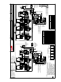
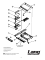
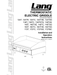
SELECTRONIC
ELECTRIC GRIDDLE
Commercial & Marine
124S, 124SHE, 124SCHE
136S, 136S-SC, 136SHE
148S, 148SHE, 148SR
160S, 160SHE, 160SR, 160S-SC
172S, 172SR, 172SC
Installation and
Operation
Instructions
2M-W353 Rev. I 1/07/2015
IL1381
148S
1
SAFETY SYMBOL
These symbols are intended to alert the user to the presence of
important operating and maintenance instructions in the manual
accompanying the appliance.
FOR YOUR SAFTEY
DO NOT STORE OR USE GASOLINE OR OTHER FLAMMABLE VAPORS AND LIQUIDS IN
THE VICINTIY OF THIS OR ANY OTHER APPLIANCE.
POST IN PROMINENT LOCATION
INSTRUCTIONS TO BE FOLLOWED IN THE EVENT USER SMELLS GAS. THIS
INFORMATION SHALL BE OBTAINED BY CONSULTING YOUR LOCAL GAS SUPPLIER.
AS A MINIMUM, TURN OFF THE GAS AND CALL YOUR GAS COMPANY AND YOUR
AUTHORIZED SERVICE AGENT. EVACUATE ALL PERSONNEL FROM THE AREA.
WARNING
IMPROPER INSTALLATION, ADJUSTMENT, ALTERATION, SERVICE OR MAINTENANCE
CAN CAUSE PROPERTY DAMAGE, INJURY OR DEATH. READ THE INSTALLATION,
OPERATION & MAINTENANCE INSTRUCTIONS THOROUGHLY BEFORE INSTALLING OR
SERVICING THIS EQUIPMENT.
WARNING
RISK OF FIRE OR ELECTRIC SHOCK
DO NOT OPEN
WARNING, TO REDUCE THE RISK OF ELECTRICAL SHOCK, DO NOT REMOVE
CONTROL PANEL. NO USER-SERVICABLE PARTS INSIDE.
REPAIRS SHOULD BE DONE BY AUTHORIZED SERVICE PERSONNEL ONLY.
NOTICE
Using any part other than genuine Lang factory supplied parts relieves the manufacturer of all
liability.
Lang reserves the right to change specifications and product design without notice. Such
revisions do not entitle the buyer to corresponding changes, improvements, additions or
replacements for previously purchased equipment.
Due to periodic changes in designs, methods, procedures, policies and regulations,
the specifications contained in this sheet are subject to change without notice. While
Lang exercises good faith efforts to provide information that is accurate, we are not
responsible for errors or omissions in information provided or conclusions reached as a
result of using the specifications. By using the information provided, the user assumes all risks
in connection with such use.
MAINTENANCE AND REPAIRS
Contact your local dealer for service or required maintenance. Please record the model number, serial
number, voltage and purchase & Installation Information in the area below and have it ready when you
call to ensure a faster service.
Model No.:
Purchased From:
Serial No.:
Location:
Voltage:
Purchase Date:
1-Phase or 3 Phase:
Installed Date:
2
PROBLEMS, QUESTIONS or CONCERNS
Before you proceed consult you authorized Lang service agent directory
or
Call the Lang Technical Service & Parts Department at 314-678-6315.
TABLE OF CONTENTS
Specifications . . . . . . . . . . . . . . . . . . . . . . . . . . . . . 4 - 5
Equipment Description . . . . . . . . . . . . . . . . . . . . . . . . . 6
Unpacking. . . . . . . . . . . . . . . . . . . . . . . . . . . . . . . .7
Installation
Leg Installation . . . . . . . . . . . . . . . . . . . . . . . . . . . 8
Ventilation & Clearence . . . . . . . . . . . . . . . . . . . . . . .9
Electrical Connection. . . . . . . . . . . . . . . . . . . . . . . . 9
Technical Data. . . . . . . . . . . . . . . . . . . . . . . . . . . .9
Phasing . . . . . . . . . . . . . . . . . . . . . . . . . . . . . . .9
Initial Start-Up
Pre-Power On. . . . . . . . . . . . . . . . . . . . . . . . . . . 10
Power On . . . . . . . . . . . . . . . . . . . . . . . . . . . . . 10
Seasoning Cooking Surface. . . . . . . . . . . . . . . . . . . . 10
Operation
General. . . . . . . . . . . . . . . . . . . . . . . . . . . . . . . 11
Operations. . . . . . . . . . . . . . . . . . . . . . . . . . . . . 11
Suggested Times and Temperatures. . . . . . . . . . . . . . . . 11
Maintenance
Cleaning. . . . . . . . . . . . . . . . . . . . . . . . . . . . . . 12
Troubleshooting
Symptoms / Possible Causes. . . . . . . . . . . . . . . . . . . 13
Possible Causes / Test . . . . . . . . . . . . . . . . . . . . . . . 14
Wiring Diagram
208/240VAC. . . . . . . . . . . . . . . . . . . . . . . . . . . . 480VAC . . . . . . . . . . . . . . . . . . . . . . . . . . . . . . 380VM. . . . . . . . . . . . . . . . . . . . . . . . . . . . . . . 5’ 480V, w/CSE12 Hoods . . . . . . . . . . . . . . . . . . . . . 15
16
17
18
Exploded View & Parts List . . . . . . . . . . . . . . . . . . . . . 19-27
NOTICE Service on this or any other Lang appliance must be performed by qualified
personnel only. Consult your Lang Authorized Service Agent Directory.
You can call our tech service number 314-678-6315 or visit our website
www.langworld.com for the service agent nearest you.
3
EQUIPMENT SPECIFICATIONS
Model
124
136
148
160
172
6.8”
Elec. Connect.
Height x Width x Depth
Clearance from
(Not including legs)
combustible surface
Weight
Actual
Shipping
15.0" x 24.0" x 28.2"
243 lbs.
280 lbs.
381mm x 610mm x 717mm
110 kg
127 kg
15.0" x 36.0" x 28.2"
368 lbs.
410 lbs.
381mm x 914mm x 717mm
167 kg
186 kg
15.0" x 48.0" x 28.2"
Sides: 2"
483 lbs.
515 lbs.
381mm x 1219mm x 717mm
Back: 2"
220 kg
234 kg
15.0" x 60.0" x 28.2"
621 lbs.
665 lbs.
381mm x 1524mm x 717mm
282 kg
302 kg
15.0" x 72.0" x 28.2"
724 lbs.
800 lbs.
381mm x 1830mm x 717mm
329 kg
364 kg
Freight
Class
85
36”
Elec. Connect.
(160 & 172 only)
D
W
H
IL1547
4” (101.6mm)
4
2.5”
Elec. Connect.
EQUIPMENT SPECIFICATIONS
Current Model
Volts AC
Hz.
PHASE
Kw
TOT.
Amp
1PH.
124S
124SC
124S-480V
124SHE
124SHE-480F
124SCHE
136S
136S-380V
136S-480V
136SHE-480V
136SB-WB
136SHE
136SCHE
136SC
136S-SC
136SC
148S
148S-380V
148S-480V
148SHE-480V
148S-SC
160S
160S-480V
160SC
160SHE
160SHE-480V
160SCHE-480V
160SR
160S-SC
160S-WB
172S
172S-480V
172SR
172S-SC
208/240
208/240
480
208/240
480
208/240
208/240
380
480
480
208/240
208/240
208/240
208/240
208/240
480V
208/240
380
480
480
208/240
208/240
480
208/240
208/240
480
480
208/240
208/240
208/240
208/240
480
208/240
208/240
60
60
60
60
60
60
60
50/60
60
60
60
60
60
60
60
60
60
50/60
60
60
60
60
60
60
60
60
60
60
60
60
60
60
60
60
1/3
1/3
3
1/3
3
1/3
1/3
3
3
3
1/3
1/3
1/3
1/3
1/3
3
1/3
3
3
3
1/3
1/3
3
1/3
1/3
3
3
1/3
1/3
1/3
1/3
3
1/3
1/3
12
12
12
12
12
12
18
18
18
18
18
18
18
18
18
18
24
24
24
24
24
1
12
12
12
12
12
12
12
12
18
18
18
18
58
58
Supply
Wire
1 PH
4
4
58
4
58
87
4
2
87
87
87
87
87
2
2
2
2
2
116
1
116
58
1
2
58
58
4
2
58
58
58
87
2
2
2
2
87
87
2
2
Current Model
124S-208VM
124S-440VM
Volts AC
208/240
440V
Hz.
Ph.
Kw Amp
TOT. 1PH
60
1/3 12
50/60 3 10.1
Supply
Wire
1 PH
58
4
87
2
Amp 3 Ph
L1
L2
L3
50
29
29
50
29
29
22
13
13
50
29
29
22
13
13
50
29
29
50
50
50
27.3 27.3 27.3
22
22
22
22
22
22
50
50
50
50
50
50
50
50
50
50
50
50
50
50
50
21.6 21.6 21.6
75
75
50
41
41
27
33
33
22
33
33
22
75
75
50
50
29
29
22
13
13
50
29
29
50
29
29
22
13
13
22
13
13
50
29
29
50
29
29
50
29
29
50
50
50
22
22
22
50
50
50
50
50
50
Amp 3 Ph
Supply
Kw Amp
Wire 3
TOT. 1PH.
PH
6
6
12
6
12
6
6
10
12
10
6
6
6
6
6
10
3
6
8
8
3
6
18
87
12
18
6
18
87
6
18
87
12
18
12
18
6
18
87
6
18
87
6
18
87
6
18
87
12
18
6
18
87
6
18
87
L1
L2
L3
Supply
Wire
3 PH
50
20
29
12
29
12
6
12
22
13
13
12
50
50
50
6
2
60
3
12
60
1/3
18
136S-380VM
380V
60
3
18
27.3
27.3
27.3
10
440V
60
3
18
23.6
23.6
23.6
12
136S-480VM
480V
60
3
18
22
22
22
12
148S-480VM
480V
60
3
24
33
33
22
8
208/240V
60
1/3
12
50
29
29
6
18
440V
60
3
18
23.6
23.6
23.6
12
18
208/240V
60
1/3
18
50
50
50
6
18
480V
60
3
18
22
22
22
12
18
160S-M
172S-440VM
172SM
172S-480VM
58
87
2
2
2
2
87
480V
136SC-440VM
2
2
2
2
Supply
Wire
1 PH
208/240V
50
22
50
50
22
22
50
50
50
50
22
50
50
2
2
Amp
1PH
136SC-208VM
Supply
Wire
L1 L2 L3 3 PH
Amp 3 Ph
2
Kw
TOT.
124S-480VM
136S-440VM
Supply
Wire
1 PH
50
22
50
50
22
22
50
50
50
50
22
50
50
Amp 3 Ph
L1
L2
L3
50
50
50
23.6 23.6 23.6
87
2
50
22
50
50
22
22
50
50
50
50
22
50
50
6
12
6
6
12
12
6
6
6
6
12
6
6
Supply
Wire
3 PH
6
12
50
50
50
6
22
22
22
12
SPECIFICATIONS MARINE
MARINE EQUIPMENT IS APPROVED FOR INSTALLATION ONLY ON VESSELS GREATER THAN
65 FEET IN LENGTH, IN ACCORDANCE WITH USCG REGULATIONS IN TITLE 46 CFR 110-113.
ANY WIRING USED IN THE INSTALLATION 5OF THIS APPLIANCE MUST BE STRANDED COPPER.
EQUIPMENT DESCRIPTION
1” Griddle Surface
Rear Gutter
(certian models)
Gutter
Grease Pan
Legs
IL1548
Main Section
Power Switch
Section
Power Switch
Section
Temp. Dial
Exterior Construction
The griddle dimensions are 17” (43.18cm) High, 30” (76.20cm) Deep, and width is dependent on the
actual model number.
The Sides, Bottom, and Rear wall are constructed of double wall stainless steel, which allows closer
installation to combustible surfaces.
The griddle surface is made of 1” thick, highly polished steel to reduce hot and cold spots, recovery
problems, warping, and ensure even heat to the edges of the griddle.
Controls
Each twelve-inch section has its own temperature selector switch that snaps into place to lock in any
temperature from 175°F to 450°F (79°C to 232°C) in 25° increments.
Each twelve-inch section of the griddle is controlled by an area sensitive RTD probe, which can sense
and react to a temperature change of +/- 4°F.
Each twelve-inch section has a set of 6 K.W. elements for high efficiency, quick recovery and outstanding
performance
Technical
The 100 Series Selectronic griddle operates on either 208/240V or 480V, at either single or three phase.
This must be specified when ordering.
Minimum clearances: 2” from side and back
NOTICE
The data plate is on the right side of the griddle. The oven voltage,
wattage, serial number, wire size, and clearance specifications are
on the data plate. This information should be carefully read and
understood before proceeding with the installation.
6
UNPACKING
Receiving the Griddle
Upon receipt, check for freight damage, both visible and concealed.
Visible damage should be noted on the freight bill at the time of delivery and
signed by the carrier’s agent. Concealed loss or damage means it does not
become apparent until the merchandise has been unpacked. If concealed
loss or damage is discovered upon unpacking, make a written request for
inspection by the carrier’s agent within 15 days of delivery. All packing
material should be kept for inspection. Do not return damaged
merchandise to Star Manufacturing Company. File your claim with the
carrier.
Location
Prior to un-crating, move the oven as near to its intended location as practical. The crating will help
protect the unit from the physical damage normally associated with moving it through hallways and
doorways.
Un-crating
The griddle will arrive completely assembled inside a wood frame and strapped to a skid. Cut the
straps and remove the wood frame.
The oven can now be removed from the skid.
THE UNIT IS EXTREMELY HEAVY. FOR SAFE HANDLING, INSTALLER
SHOULD OBTAIN HELP AS NEEDED, OR EMPLOY APPROPRIATE MATERIALS
CAUTION HANDLING EQUIPMENT (SUCH AS A FORKLIFT, DOLLY, OR PALLET JACK)
TO REMOVE THE UNIT FROM THE SKID AND MOVE IT TO THE PLACE OF
INSTALLATION.
ANY STAND, COUNTER OR OTHER DEVICE ON WHICH OVEN WILL BE
LOCATED MUST BE DESIGNED TO SUPPORT THE WEIGHT OF THE GRIDDLE.
SHIPPING STRAPS ARE UNDER TENSION AND CAN SNAP BACK WHEN CUT.
7
INSTALLATION
IL1549
Std Leg
Marine Bolt Down Leg
Above: typical leg installation.
Leg Installation
There are four, 4” legs provided for 2, 3 and
4 foot griddles.
2.5”
There are eight 4” legs provided for 5 and 6
foot griddles.
The legs are shipped in the grease drawers
of the griddle. Install them into the threaded
holes on the underside of the griddle body.
IL1550
For bolt down legs see above illustration for dimensions.
Leveling adjustment may be done by screwing the bottom portion of the leg in and out.
DANGER:
THIS APPLIANCE MUST BE GROUNDED AT THE TERMINAL PROVIDED.
FAILURE TO GROUND THE APPLIANCE COULD RESULT IN ELECTROCUTION
AND DEATH.
INSTALLATION OF THE UNIT MUST BE DONE BY PERSONNEL QUALIFIED TO
WORK WITH ELECTRICITY AND PLUMBING. IMPROPER INSTALLATION CAN
WARNING CAUSE INJURY TO PERSONNEL AND/OR DAMAGE TO EQUIPMENT. UNIT
MUST BE INSTALLED IN ACCORDANCE WITH ALL APPLICABLE CODES.
NOTICE:
The data plate is located behind access panel between controls and grease
drawer. The grill voltage, wattage, serial number, wire size, and clearance
specifications are on the data plate. This information should be carefully
read and understood before proceeding with the installation.
NOTICE:
The installation of any components such as a vent hood, grease extractors,
fire extinguisher systems, must conform to their applicable National, State
and locally recognized installation standards.
ALWAYS KEEP THE AREA NEAR THE APPLIANCE FREE FROM
COMBUSTIBLE MATERIALS.
CAUTION
KEEP FLOOR IN FRONT OF EQUIPMENT CLEAN AND DRY. IF SPILLS
OCCUR, CLEAN IMMEDIATELY, TO AVOID THE DANGER OF SLIPS OR FALLS.
8
INSTALLATION cont.
Ventilation and Clearances
Standard minimum clearance from combustible construction is as follows.
2” from side
2” from back
These griddles may be set directly, without legs, on a curbed base or non-combustible surface.
If the griddle is set without legs on a non-combustible floor or a curbed base, maintain a 4-inch
back clearance.
Do not install the griddle directly against a non-combustible back wall or surface.
Do not install the griddle closer than 12 inches from an uncontrolled heat source (char broiler etc.).
Keep the appliance area free and clear of combustible material and do not obstruct the flow of
combustion or ventilation air.
Electrical Connection
There is one power supply connection on the 2, 3, and 4-foot griddles. There are two power
supply connections on 5 and 6-foot griddles. Refer to the power supply chart in the Technical
Data portion of this manual, for proper power supply size.
There is (1) one 1 1/4-inch conduit knockout on 2, 3 and 4-foot griddles located at the rear of the
griddle, through the back and the bottom of the griddle body. There are (2) two 1 1/4-inch conduit
knockouts provided on the 5 and 6-foot griddles. Use a supply wire suitable for at least 90 degree
centigrade.
This Selectronic griddle is shipped from the factory, wired for 208/240 or 480 volts, the 208/240
griddle is a dual voltage design. Jumper wires on terminal strip next to the main power supply
connection determine the griddle voltage. For a 208-volt power supply, leave the jumpers in place.
For a 240-volt power supply disconnect the jumpers as indicated on the tag on the terminal strip.
The 480-volt griddle can be operated on 480 volts only and must be specified when ordering.
Technical Data
NOMINAL AMPS PER LINE
THREE PHASE
MODEL
NUMBER
TOTAL
K.W.
208 Volt
SINGLE PHASE
240 Volt
L1
L2
L3
L1
480 Volt
L2
L3
L1
L2
L3
208V
240V
24”
12
50
28.8
28.8
43.3
25
25
21.7
12.5
12.5
57.7
50
36”
18
50
50
50
43.3
43.3
43.3
21.7
21.7
21.7
86.5
75
24
75
75
50
65
65
43.3
32.5
32.5
21.7
115.5
100
18
50
50
50
43.3
43.3
43.3
21.7
21.7
21.7
86.5
75
48”
#1
60”
72”
#2
12
50
28.8
28.8
43.3
25
25
21.7
12.5
12.5
57.7
50
#1
18
50
50
50
43.3
43.3
43.3
21.7
21.7
21.7
86.5
75
#2
18
50
50
50
43.3
43.3
43.3
21.7
21.7
21.7
86.5
75
PHASING BY WIRE NUMBER
Phasing
All griddles are shipped from the
factory set up for a three-phase
service. Rearrange the wires in
the power supply terminal block to
convert the griddle to single phase.
Re-phasing the griddle is not
chargeable to Lang Manufacturing
Company as warranty. To convert
to single-phase have a Lang
Authorized Service Agent, follow
this chart.
MODEL
NUMBER
124S
9
THREE PHASE
SINGLE PHASE
LINE 1
LINE 2
LINE 3
LINE 1
LINE 2
1,4
2
3
1,3
2,6
136S
1,4
2,5
3,6
1,3,5
2,4,6
148S
1,4,7
2,5,8
3,6,9
1,3,5,7
2,4,6,8
160S #1
1,4
2,5
3,6
1,3,5
2,4,6
160S #2
1,4
2
3
1,3
2,6
172S #1
1,4
2,5
3,6
1,3,5
2,4,6
172S #2
1,4
2,5
3,6
1,3,5
2,4,6
INITIAL START UP
Pre-Power On
Before starting the griddle for the first time, clean the griddle body and cooking surface.
Use a mild soap and water solution, then rinse with clear water and dry.
Power On
Set the main power switch, located at the far left of the control panel, to the “ON” (up) position
(there are two “ON” switches on 5 and 6 foot griddles).
Set each cooking section’s power switch, located next to each temperature dial, to the “ON” (up)
position.
Set the temperature dials to 200°F.
Heat the griddle at 200°F (93°C) for 2 hours to evaporate any moisture that may be in the elements.
After 2 hours at 200°F (93°C), turn the temperature up to 350°F (176°C) for ½ hour.
After the griddle reaches 350°F (176°C) for ½ hour, turn the griddle up another 50°F (10°C) for another
½ hour and repeat this until it is at 450°F (232°C) for ½ hour.
The unit may emit a small amount of smoke as the cooking surface passes the 300°F (148°C) point.
Do not be alarmed as the smoke is caused by oils associated with the manufacturing process and will
stop when the griddle reaches 350°F (176°C).
Seasoning Cooking Surface (Non-Chrome Only)
The cooking surface must be “seasoned” in order to eliminate product sticking during cooking.
To season, heat the griddle to 250°F (121°C).
Once at 250°F (121°C), coat the cooking surface with non-salted vegetable oil.
Allow the griddle to stand at 250°F (121°C) until the cooking surface looks dry then coat it again.
Heat the griddle to 350°F (176°C) and repeat the procedure.
NOTICE:
During the first few hours of operation you may notice a small
amount of smoke coming off the griddle, and a faint odor from the
smoke. This is normal for a new griddle and will disappear after the
first few hours of use.
10
OPERATION
General
The suggested time and temperature chart (below) is provided as a guide for the products listed only.
If different temperature settings are to be used, select one side of the griddle and operate at the lowest
temperature. Adjoining sections should be set at progressively higher temperatures. Do not try to
operate the end sections hot and the center sections cool.
ALWAYS KEEP THE AREA NEAR THE APPLIANCE FREE FROM
COMBUSTIBLE MATERIALS.
CAUTION KEEP FLOOR IN FRONT OF EQUIPMENT CLEAN AND DRY. IF
SPILLS OCCUR, CLEAN IMMEDIATELY, TO AVOID THE DANGER OF
SLIPS OR FALLS.
Operations
An understanding of how the griddle sections are controlled will be a valuable aid in loading product on
your unit.
Each 12-inch section of your griddle is independently controlled by a temperature controller. The
temperature control sensor is mounted in the center of each cooking section under the griddle plate.
If the product is loaded directly over the temperature sensor, that section will turn on and the burner will
heat the entire cooking section. If the product is loaded to the side, front or back of the temperature
sensor, the thermostat will react to the temperature change much slower.
During slow periods with minimal loads, do not load directly over the thermostat sensors as this will
unnecessarily turn the burners on and overheat the remainder of the section not being utilized.
SUGGESTED TIMES AND TEMPERATURES
PRODUCTS
TEMPERATURE
F/C
TIME (MIN)
HAMBURGER
2 patties per LB
4 patties per LB
350°F / 176°C
6 patties per LB
6 to 8
4 to 6
3 to 4
STEAKS
1/2 to 3/4 inch thick, cooked medium
3/4 to 1 inch thick, cooked medium
Lamb Chops
Pork Chops
Salmon
Halibut
Snapper
Hash Brown Potatoes
Bacon
Sausage Links or Patties
375°F / 190°C
350°F / 176°C
350°F / 176°C
325°F / 162°C
375°F / 190°C
350°F / 176°C
5 to 7
8 to 10
6 to 8
6 to 8
6 to 8
6 to 8
6 to 8
3 to 4
3 to 4
3 to 4
Ham (Pre-cooked)
375°F / 190°C
2
Eggs
275°F / 135°C
2 to 4
Note: The times and temperatures in this chart are intended as a general guide and starting
point. Your actual times and temperatures may vary from this chart.
11
Turn the product and continue cooking
until it has reached its desired degree
of doneness.
Remove the product from the griddle.
When reloading the griddle, first
use the griddle surface on which a
previous load was not placed. This
will help insure the proper griddle
temperature.
MAINTENANCE & CLEANING
Cleaning
•
•
•
•
Always start with a cold griddle.
The stainless exterior can easily be cleaned using a good non-abrasive cleaner.
Always follow the cleaner manufacturer’s instructions when using any cleaner.
Always apply these cleaners when the griddle is cold and rub in the direction of the metal’s grain.
Griddle Surface Care (non-chromium surfaces)
It takes very little time and effort to keep the griddle attractive and performing at top efficiency. If grease
is permitted to accumulate, it will form a gummy cake and then carbonize into a hard substance which is
extremely difficult to remove. To prevent this condition, the following suggestions for cleanliness should be
followed:
•
After each use, scrape the griddle with a scraper or flexible spatula to remove excess grease and
food. A waste drawer is provided for the scrapings. If there is an accumulation of burned on grease
and food, the griddle should be thoroughly scoured and re-seasoned. Use pumice or griddle stone
while the griddle is warm.
Do not use steel wool because of the danger of steel slivers getting into the food.
Griddle Care (Chromium Surfaces)
It takes very little time and effort to keep this Industrial Chromium griddle surface sparkling clean and
performing at top efficiency. DO NOT allow grease to accumulate as it will carbonize and become difficult to
remove. To prevent this condition the following cleaning suggestions should be followed:
1.
Remove excess grease and food regularly with a 4” (100mm) wide Razor Sharp type scraper and
wipe surface with a damp cloth if desired.
2.
Following the scraping, for end of the day cleaning, a damp cloth and a non-silicated, nonabrasive,
non-chlorinated cleaner such as Bon-Ami may be used to wipe surface clean, followed by wiping with
a clean wet cloth.
3.
Follow steps 2 and 3 from Griddle Care (Non-Chromium Surfaces) above.
CAUTION
1. Never use pumice, griddle stones, or abrasives on a chromium surface.
2. Never strike a chromium griddle surface with a sharp instrument or spatula edge.
3. Never use steel wool.
4. Never use commercial liquid grill cleaner on the griddle surface.
5. Abusing surface voids the warranty.
KEEP WATER AND SOLUTIONS OUT OF CONTROLS. NEVER SPRAY
OR HOSE CONTROL CONSOLE.
WARNING
CAUTION
NOTICE:
MOST CLEANERS ARE HARMFUL TO THE SKIN, EYES, MUCOUS
MEMBRANES AND CLOTHING. PRECAUTIONS SHOULD BE TAKEN
TO WEAR RUBBER GLOVES, GOGGLES OR FACE SHIELD AND
PROTECTIVE CLOTHING. CAREFULLY READ THE WARNING AND
FOLLOW THE DIRECTIONS ON THE LABEL OF THE CLEANER TO BE
USED.
Never leave a chlorine sanitizer in contact with stainless steel surfaces
longer than 10 minutes. Longer contact can cause corrosion.
12
TROUBLESHOOTING
Symptoms
What follows is a chart of symptoms and possible causes to aid in diagnosing faults with the griddle.
Refer to the Symptoms column to locate the type of failure then to the possible cause for the items
to be checked.
To test for a possible causes refer to the TEST section and locate the possible cause then refer
to test to identify test procedures.
SYMPTOM
POSSIBLE CAUSE
•         No Power to Griddle
Whole Griddle will not heat
•         Failed Power switch
•         Failed Transformer.
•         Failed Power switch (for that section)
•         Failed Probe
•         Failed Circuit board
One Section will not heat
•         Failed 12-position switch
•         Failed contactor
•         Failed Element.
•         Product left on griddle too long
•         Failed Probe
Product Burning
•         Failed Circuit board
•         Failed 12-position switch
•         Product removed too soon
•         Failed Probe
Product Under cooked
•         Failed Circuit board
•         Failed 12-position switch
13
TROUBLESHOOTING continued
NOTICE:
Service on this, or any other, LANG appliance must be performed by qualified
personnel only. Consult your Lang Authorized Service Agent Directory or call
the factory at 314-678-6315, or WWW.LANGWORLD.COM
For the service agent nearest you.
BOTH HIGH AND LOW VOLTAGES ARE PRESENT INSIDE THIS APPLIANCE
WHEN THE UNIT IS PLUGGED/WIRED INTO A LIVE RECEPTACLE. BEFORE
WARNING REPLACING ANY PARTS, DISCONNECT THE UNIT FROM THE ELECTRIC
POWER SUPPLY.
If an item on the list is followed by an asterisk (*), the work should be done by a factory authorized service
representative.
POSSIBLE
CAUSE
Product is cooked too long
• No test available, operational condition
Failed Probe
• Check probe for proper resistance*
Failed Circuit board
• Confirm that Circuit board is getting correct
voltage and putting out correct voltage*
Failed Transformer
• Check both Primary and Secondary coils for
correct voltage*
Failed Contactor
Failed Element
CAUTION
TEST
• Remove the wires from the contactor coil and
check for continuity across the contactor coil
connection*
• Ensure the contactor moveable points move
freely up and down*
• Confirm that Elements are getting correct
voltage and have continuity*
USE OF ANY REPLACEMENT PARTS OTHER THAN THOSE SUPPLIED BY
LANG OR THEIR AUTHORIZED DISTRIBUTORS CAN CAUSE BODILY INJURY
TO THE OPERATOR AND DAMAGE TO THE EQUIPMENT AND WILL VOID ALL
WARRANTIES.
14
48”
36”
“24
1
1
1
1
ELEMENT HOOKUP
208V
240V
INSTALL
JUMPER
REMOVE
JUMPER
4
4
10
10
21
23
24
10
17
19
20
24
13
15
20
16
4
12
12
25
25
4
18
9
11
16
25
25
22
10
4
14
4
12
2
29
29
28
28
27
27
26
32
26
1 GRIDDLE ELEMENTS
30
32
30
2 GRIDDLE PILOT LAMP
8
3 CONTACTOR
4 JUMPER
5 TERMINAL BLOCK
3
6 TEMP. CONTROL BOARD
3
3
3
7 12 POSITION SWITCH
31
8 TOGGLE SWITCH
9 TRANSFORMER
8
10 PROBE
8
8
31
8
1
2
3
4
5
6
7
8
9
10
2
3
4
5
6
7
8
9
10
2
3
1
4
2
5
4
3
2
1
3
1
5
4
3
2
1
5
7
12
POSITION
SWITCH
7
12
POSITION
SWITCH
7
12
POSITION
SWITCH
5
L3
4
6
5
4
3
2
1
L2
5
7
6
5
4
3
2
1
8
L1
6
9
7
6
6
7
12
POSITION
SWITCH
6
8
10
1
2
3
4
5
6
7
8
9
10
9
NOTE: 60” & 72” HAVE TWO POWER SUPPLY CONNECTIONS
60”: CONN # 1 USE LG36
CONN # 2 USE LG24
72”: CONN # 1 USE LG36
CONN # 2 USE LG36
SERVICE CONNECTIONS
MODEL
DWN. BY :
DLG
DESCRIPTION:
CAD FILE :
DWN. DATE :
K.W.
61114-14
DWG. NO:
FROM ACAD
SHEET
1
OF
1
B
REV:
SINGLE PHASE
L2-L3
L3-L1
TOTAL
L1
L2
L3
L1
L2
24
6.0
0.0
6.0
12.0
1,4
2
3
1,3
2,4
36
6.0
6.0
6.0
18.0
1,4
2,5
3,6
1,3,5
2,4,6
48
12.0
6.0
6.0
24.0
1,4,7
2,5,8
3,6
1,3,5,7
2,4,6,8
12-10-03
W/D GRIDDLE 208/240VAC
THREE PHASE
L1-L2
LG36
Note:
LG24
1. Add one more section for a single
connection “48
2. Add two more sections for a 60”
3. This wiring diagram shows 1/2 section
for a 72” model
4. Do not use more than 4 contactors to
one transformer
1
1
10
1
10
10
17
9
13
20
16
12
1 GRIDDLE ELEMENTS
2 GRIDDLE PILOT LAMP
28
28
27
26
27
26
3 CONTACTOR
4 JUMPER
5 TERMINAL BLOCK
6 TEMP. CONTROL BOARD
7 12 POSITION SWITCH
3
3
3
8 TOGGLE SWITCH
31
9 TRANSFORMER
10 PROBE
8
8
31
480V
8
9
6
6
1
2
3
4
5
6
7
8
9
10
2
6
60”: CONN # 1 USE LG36
CONN # 2 USE LG24
6
5
4
24V
30
2
3
1
7
SRC
5
4
3
2
1
7
L1
L2
DWN. DATE : 10-28-96
DESCRIPTION:
LANG-GRIDDLE
CAD FILE : FROM ACAD
480VAC SELECTRONIC
61114-17
DWG. NO:
15
SHEET1 OF
1
12
POSITION
SWITCH
12
POSITION
SWITCH
12
POSITION
SWITCH
5
4
3
2
1
5
4
3
2
1
8
72”: CONN # 1 USE LG36
CONN # 1 USE LG36
DWN. BY :
3
4
5
6
7
8
9
10
1
2
3
4
5
6
7
8
48”: CONN # 1 USE LG24
CONN # 2 USE LG24
9
10
NOTE: SOME 48” AND ALL 60” & 72” GRIDDLES HAVE
TWO POWER SUPPLY CONNECTIONS
C
REV:
L3
5
7
30
32
32
2
8
6
7
4
5
3
RE V
D E S C R IP TIO N
- E C O 5956, IN ITIA L R E LE A S E , R E P LA C E D 61114-17
C
D JS
D JS
E C O 10647. R em oved O vertem p S tats
Note:
LG36
or 136S
1. Add one more section for a single
connection LG-48 (148S)
2. Add two more sections for a LG-60 (160S)
3. This wiring diagram shows 1/2 section
for a LG-72 (172S) model
4. Do not use more than 4 contactors to
one transformer
R E V B Y R E V D A TE C H K B Y C H K D A TE
D JS
7/25/2007
E C O 6254 R evis e w ire num bers to m atc h produc tion,
add w ire nuts to m atc h produc tion
A
B
D
1
5
D
1
10
6
10/26/2007
5/10/2011
LG24
or 124S
1
10
1
2
R E V IS IO N S
10
4
3
2
1
C
1 GRIDDLE ELEMENTS
2 GRIDDLE PILOT LAMP
3 CONTACTOR
28
4 JUMPER
5 TERMINAL BLOCK
27
28
27
26
26
6 TEMP. CONTROL BOARD
31
7 12 POSITION SWITCH
8 TOGGLE SWITCH
31
9 TRANSFORMER, CLASS 2
10 PROBE
3
3
3
480V
8
NOTE: SOME LG48 (148S) AND ALL LG60 (160S) & LG72 (172S) HAVE
TWO POWER SUPPLY CONNECTIONS
L1
22
22
33
43
43
L2
13
22
33
33
43
M odel
24
36
48
UNLESS OTHERWISE SPECIFIED
DIMENSIONS ARE IN INCHES.
TOLERANCES ARE:
8
.X = ± .05
.XX = ± .03
.XXX = ± .015
7
1
2
3
4
5
6
ANGLES
± .5°
L1
1,4
1,4
1,4,7
Three P has e
L2
2
2,5
2,5,8
7
32
L1
L2
DESCRIPTION:
6
REV. BY :
REV. DATE :
CHK. BY :
LANG-GRIDDLE 480VAC SELECTRONIC
5
5
L3
A
BLANK
DIMS. :
MATERIAL
TYPE :
DWN. DATE : 7/25/07
32
2
30
L3
3
3,6
3,6
MATERIAL
PART # :
DWN. BY : DJS
8
30
5
4
3
2
1
12
POSITION
SWITCH
7
BLU
7
8
9
10
2
3
4
5
6
7
5
4
3
2
1
7
SERVICE CONNECTIONS
L3
13
22
22
33
43
DECIMALS
2 1
4 3
12
POSITION
SWITCH
12
POSITION
SWITCH
M odel
24
36
48
60
72
6
6 5
5
4
3
2
1
AMP TOTAL
8
6
LG72 (172S): CONN # 1 USE LG36 (136S)
CONN # 1 USE LG36 (136S)
16
4
B
24V
YEL
6
9
10
1
2
3
4
5
6
7
10
8
9
LG60 (160S): CONN # 1 USE LG36 (136S)
CONN # 2 USE LG24 (124S)
A
8
LG48 (148S): CONN # 1 USE LG24 (124S)
CONN # 2 USE LG24 (124S)
9
B
8
CHK. DATE :
sq
in
BLANK
AREA:
X
SHEET 1 OF 1
CAD FILE :
DWG. NO: 2M-61114-W50 REV:
3
2
1
B
10
9
8
5
7
6
3
27
5
4
1
2
3
3
4
11
12
7
TO CONNECTION POINT C
ON 2ND HOOD CONTACTOR BOX
9
5
3
15
6
4
B
GRIDDLE RIGHT
1
TO CONNECTION POINT A
ON 2ND HOOD CONTACTOR BOX
6
10
2
27
13
10
16
8
15
9
7
C
5
7
6
9
3
26
DOWN
UP
3
10
9
2
1
30
17
17
10
16
HOOD
POSITION
#1
14
26
7
22
1
24V
480V
2
32
31
11
30
TRANSFORMER
3
8
5
4
HOOD
POSITION
#3
HOOD
POSITION
#4
FRONT OF GRIDDLE
HOOD
POSITION
#2
OVERTEMP STAT
ITEM #19
TOP VIEW OF GRIDDLE
14
27
32
31
GRIDDLE WIRES
ONLY TO TERMINAL
BLOCK 4
1
OVERTEMP STAT
ITEM #13
18
16
A
6
10
2
26
2
9
1
2
3
4
GRIDDLE FIELD
WIRING NOTE:
THREE PHASE
L1 - 1,4
L2 - 2
L3 - 3
HOOD
POSITION
#5
OVERTEMP STAT
ITEM #20
9
7
3
28
TABLE 1
5
8
HOOD POSITION #
1
2
3
4
5
1,2
1,3
1,4
1,5
2,3
2,4
2,5
3,4
3,5
4,5
1,2,3
1,2,4
1,2,5
1,4,5
CLAMSHELL FIELD
WIRING NOTE
1 OR 3 PHASE
L1 - 26
L2 - 27
7
21
20
9
1
TO 2ND HOOD TILT SWITCH
20
10
1
7
ANGLES
1
3
28
5
7
3
27
6
10
2
27
1
2
3
3
4
5
13
13
19
20
20
13
13,19
13,20
13,20
19
13,20
13,20
19,20
19,20
20
13,19
13,20
13,20
13,20
TO CONNECTION POINT C
ON 2ND HOOD CONTACTOR BOX
6
12
3
7
MODEL NO.
2M-61114-W65
PART NO.
26
REV.
18
1
31
31
32
30
17
17
10
16
13,19 & 20
26
12
14
7
32
2
22
8
1
24V
480V
30
3
4
2
3
WIRING NOTE
SINGLE PHASE
L1 - 27,29
L2 - 26,28
1
4
GRIDDLE FIELD
WIRING NOTE:
THREE PHASE
L1 - 1,4
L2 - 2,5
L3 - 3,6
21
DR
TO CONNECTION POINT C
ON 3RD HOOD CONTACTOR BOX
14
28
14
THREE PHASE
L1 - 26
L2 - 27,28
L3 - 29
29
5 CLAMSHELL FIELD
11
7
DESCRIPTION OF CHANGE
TO CONNECTION POINT B
ON 3RD HOOD CONTACTOR BOX
14
27
GRIDDLE WIRES
ONLY TO TERMINAL
BLOCK 4
2
19,20
19,20
13,20
19,20
13,20
19,20
10
9
USE OVERTEMP
STAT ITEM #
DOWN
UP
16
A
6
10
2
26
1
DATE/ECO
TITLE
W/D 5' SELECTRONIC ELECT GRID W/ CSE12 HOODS - 480V
3
TABLE 1
6
4
9
C
9
5
15
HOOD POSITION #
2,3,4
2,3,5
2,4,5
3,4,5
1,2,4,5
2,3,4,5
ALL OTHER
COMBINATIONS
5
15
B
GRIDDLE LEFT
4
11
13
13
REVISIONS
TO CONNECTION POINT A
ON 2ND & 3RD HOOD CONTACTOR BOX
5
16
9
1
TO CONNECTION POINT B
ON 2ND HOOD CONTACTOR BOX
6
17
19
USE OVERTEMP
STAT ITEM #
6
10
2
1
DATE: 10/12/2009
SEE NOTES 2 & 3
TOLERANCE: UNLESS NOTED: .xxx ± .015
6
THIS DRAWING CONTAINS INFORMATION CONFIDENTIAL TO STAR MFG. INT'L
INC. NO REPRODUCTION OR DISCLOSURE OF ITS CONTENTS IS PERMITTED
5
SEE NOTES 2 & 3
1
22 GRIDDLE PILOT LAMP-28V
2
21 CLAMSHELL PILOT LAMP-250V
9
16 TIMER PLUGS
8
15 CONTACTOR - HOOD
10
14 FUSES
7
CK.
6
DR: DJS
5
R
1
20 HOOD OVERTEMP STAT #3
4
12 HOOD PILOT LAMP
3
13 HOOD OVERTEMP STAT #1
2
FINISH
8
MATERIAL
9
STAR MANUFACTURING INTERNATIONAL INC.
# 10 SUNNEN DRIVE
ST. LOUIS, MO. 63143, USA
7
19 HOOD OVERTEMP STAT #2
10
18 HOOD TILT SWITCH
1
17 HOOD ELEMENTS
3
11 TERMINAL BLOCK
2
10 OVERTEMP STAT - GRID
3
TO CONNECTION POINT B
ON 2ND HOOD CONTACTOR BOX
GRIDDLE ELEMENTS
GRIDDLE PILOT LAMP-480V
CONTACTOR - GRIDDLE
PWR CONNECT TERM BLK
TEMP CONTROL BOARD
12 POSITION SWITCH
TOGGLE SWITCH
TRANSFORMER, CL2
PROBE
2
NOTES:
1.
FUSE BLOCK PAIR REQUIED FOR EVERY 1
OR 2 CLAMSHELL COMBINATION ON EACH
POWER CONNECTION.
2.
OVERTEMP STATS ARE LOCATED ON THE
UNDERSIDE OF THE GRIDDLE PLATE.
3.
SEE TABLE 1 FOR ITEM 13,19 & 20 USAGE.
------ DASHED COMPONENTS ARE
4.
REQURED ONLY WHEN 3 HOODS ARE
USED ON ONE POWER CONNECTION.
5.
CLAMSHELL VOLTAGE MAY BE
DIFFERENT THAN GRIDDLE VOLTAGE.
SEE CLAMSHELL NAMEPLATE FOR
PROPER VOLTAGE FOR CLAMSHELL.
1
2
3
4
5
6
7
8
9
4
5
4
3
2
1
12
POSITION
SWITCH
5
1
R/W
2 3
CONTACTOR
BOX
CLAMSHELL
HOOD
4
5
4
3
2
1
12
POSITION
SWITCH
BLU/W
4
5
4
3
2
1
12
POSITION
SWITCH
6
BLU/W
5
4
3
2
1
12
POSITION
SWITCH
5
5
4
3
2
1
12
POSITION
SWITCH
R/W
1
CONTACTOR
BOX
CLAMSHELL
HOOD
4
2 3
TRANSFORMER
TO 3RD HOOD TILT SWITCH
TO 2ND HOOD TILT SWITCH
17
1
15
14
2
13
12
11
3
10
9
8
4
16
7
5
6
For individual parts
SEE DETAIL A
SOME ITEMS ARE INCLUDED FOR
ILLUSTRATIVE PURPOSES AND IN
CERTAIN INSTANCES MAY NOT BE AVAILABLE
This drawing contains information confidential
to Star Manufacturing International, Inc.
No reproduction or disclosure of it's
contents is permitted.
Model:
124S - 172S Selectronic Control Electric Griddle
LG Electric Griddle Accu-Temp Control
SK2263
18
Rev. C
1/17/12
PARTS LISTJuly 24, 2012, Rev H
FIG NO.
1
2
3
4
5
6
8
9
10
11
12
13
14
NI
NI
NI
NI
NI
NI
NI
NI
NI
NI
NI
Model: 124S, 124S-480V, 124SHE, 124SCHE, Selectronic Electric Griddle
PART NO.
K9-XL-722-15
K9-XL-722-154
K9-XL-722-C154
K9-XL-722-W152
2E-41100-17
K9-XL-228
K9-LG-BODY-2
2A-Z0314
2A-72500-05
K9-LGPS2-C
K9-LGPS2-C-W1
K9-LGPS2-U
K9-50302-07
K9-XL-441
K9-XL-434
2H-XL-424
K9-XL-439
2N-11030-29
2N-11030-31
2N-11030-48
2N-11030-30
K9-50302-14
2E-30500-02
2E-30500-07
2E-30501-03
2P-50100-05
2P-50100-051
2P-50100-052
2P-50100-15
2P-50100-15-1
2P-50100-16
2P-50100-17
QTY
1
2
1
1
4
1
1
2
2
2
2
2
2
1
1
1
1
1
1
1
DESCRIPTION
PLATE ASY 2’ SEL .5 GRV
PLTEASY 2’ SEL.5GRVW/XLH12
PLT ASSY 2’ SEL .5” GRV CHR
PLATE ASSY 2’ SEL. .5 GRV
TEMP PROBE SEL LG GRIDDLE
BUCKET SLIDE ASSY
BLANK BODY LG & XL 2FT
FOOT, 4” DIE CAST
LEG 4 W/BOLT DOWN ADJ
PNEL XL-LG SEL 2’ 208/240V
PNEL SEL 2’ 208/240V W/CSE
PNEL XL-LG SEL 2’ 480V
GREASE DRAWER LG/XL
PROBE HOLDER SELECTRONIC
ELEMENT PAN ASSEMLBY
ELEMENT PAN INSULATION
ELEMENT PAN Z ASSEMBLY
ELE GRD 208/240V4.5KW/6KW
ELMNT GRID 480V 5991W
ELE GRD 440V 5991W XL/LG
ELMNT GRID 208V 1257W
2’ GRAB BARASSY XL-LG
TRM STRP 4 POLE 30A 600V
TRM BLOCK 3PLELRGE 125AMP
TERM STRP 4 POLE W/PUSH
GROOVED GRIDDLE CLEANING
GRVED GRDLE BRUSH REPL
GRVED GRDLE BRUSH REPL
GRIDDLE SCRAPER 12”
RE-FILL REPLACEMENTS
BOM AMI CLEANER
20” PALMYRA BRUSH
APPLICATION
124S, 124S-480V
124SHE
124SCHE
124SC
124S, 124S-480V, 124SHE
ALL
ALL
124S, 124S-480V, 124SHE
MARINE
124S
124SHE
124S-480V
ALL
ALL
ALL
ALL
ALL
124S, 124S-480V & VM, 124SHE, 124SCHE
124S-480V, 124SHE-480V
124S-440VM
124S, 124S-208VM, 124S-480V, 124SHE, 124SCHE
MARINE
124S, 124S-480V, 124SHE
124S, 124S-480V, 124SHE
124S, 124S-480V, 124SHE
ALL
ALL
ALL
CROME UNITS
CROME UNITS
CROME UNITS
CROME UNITS
IMPORTANT: WHEN ORDERING, SPECIFY VOLTAGE OR TYPE GAS DESIRED
INCLUDE MODEL AND SERIAL NUMBER
Some items are included for illustrative purposes only and in certain instances may not be available.
19
PAGE 1
OF 1
PARTS LISTJuly 24, 2012, Rev H
Model No: 136S, 136S-SC, 136SHE, 136SCHE, 136S-380VM, 136S-480V
Selectronic Electric Griddle
FIG NO
1
2
3
4
5
6
7
8
9
10
11
12
13
14
15
NI
NI
NI
NI
NI
NI
NI
NI
NI
PART NO.
K9-XL-722-16
K9-XL-722-W162
K9-XL-722-164
K9-XL-722-C164
K9-XL-719-3
2E-41100-17
K9-XL-228
K9-XL-288-30
K9-LG-BODY-3
K9-LG-BODY-3WB
2A-Z0314
2A-72500-05
2A-200716
K9-LGPS3-C
K9-LGPS3-CWB
K9-LGPS3-K
K9-LGPS3-U
K9-60102-13531
K9-XL-235-1
K9-XL-235-30
K9-XL-441
K9-XL-434
2H-XL-424
K9-XL-439
2N-11030-29
2N-11030-04
2N-11030-31
2N-11030-48
2N-11030-30
K9-50302-15
2E-30500-03
2E-30500-05
2P-50100-05
2P-50100-051
2P-50100-052
2P-50100-15
2P-50100-15-1
2P-50100-16
2P-50100-17
QTY
1
3
1
1
4
1
1
1
3
3
3
3
3
3
1
1
1
1
1
1
DESCRIPTION
PLATE ASY 3’ SEL .5 GRV
PLATE ASY 3’ SEL.5 GRV CHR
PLATE ASY 3’SEL .5 GRV
PLATE ASY 3’ SEL.5 GRV CHR
PLATE ASY 3’ SEL REAR
TEMP PROBE SEL LG GRIDDLE
BUCKET SLIDE ASSY
BKT SLIDE ASSY REAR GUTER
BLANK BODY LG & XL 3FT
BLANK BODY 3’ REAR GUTTER
FOOT, 4” DIE CAST
LEG 4 W/BOLT DOWN ADJ
LEG, 2.5” METAL
PANEL XL-LG SEL 3’ 208/240V
PNELXL-LG SEL 2’ 208/240V
PANEL CL-LG SEL 3’ 380V
PANEL XL-LG SEL 3’ 480V
ACCESS PANEL ASSY 2’
GREASE BUCKET ASSY S/S
GREASE BKT ASY REAR GUTER
PROBE HOLDER SELECTRONIC
ELEMENT PAN ASSEMLBY
ELEMENT PAN INSULATION
ELEMENT PAN Z ASSEMBLY
ELE GRD 208/240V4.5KW/6KW
ELMNT GRID 380V 5991W
ELMNT GRID 480V 5991W
ELE GRD 440V 5991W XL/LG
ELMNT GRID 208V 1257W
3’ GRAB BARASSY XL-LG
TRM STRP 6 POLE 30A 300V
TRM STRP 8 POLE 30A 300V
GROOVED GRIDDLE CLEANING
GRVED GRDLE BRUSH REPL
GRVED GRDLE BRUSH REPL
GRIDDLE SCRAPER 12”
RE-FILL REPLACEMENTS
BOM AMI CLEANER
20” PALMYRA BRUSH
IMPORTANT: WHEN ORDERING, SPECIFY VOLTAGE OR TYPE GAS DESIRED
INCLUDE MODEL AND SERIAL NUMBER
APPLICATION
136S
136SC
136SHE
136SCHE
136SR
ALL
ALL
136SR
ALL
136SR
136S, 480V
MARINE
136S-SC
136S
136SR
136S-380VM
136S-480V
136S, 136SB, 136SC
ALL
136SR
ALL
ALL
ALL
ALL
136S
136S-380V, 380VM
136S-480V, 136SHE-480V
136S-440VM
136S
136SR, MARINE
136S, 480V
136S, 480V
ALL
ALL
ALL
CROME UNITS
CROME UNITS
CROME UNITS
CROME UNITS
Some items are included for illustrative purposes only and in certain instances may not be available.
20
PAGE 1
OF 1
PARTS LISTJuly 24, 2012, Rev H
Model No: 148S, 148S-480V, 148S-SC, 148S-WB
Selectronic Electric Griddle
FIG NO
1
2
3
4
5
PART NO.
K9-XL-719-4
K9-XL-722-17
K9-XL-722-174
2E-41100-17
K9-XL-228
K9-XL-228-30
K9-XL-219-6
2A-Z0314
2A-72500-05
2A-200716
QTY
1
4
1
1
4
K9-LGPS2-CWB-4
6
8
9
10
11
12
13
14
NI
NI
NI
NI
NI
NI
NI
NI
NI
NI
NI
NI
NI
NI
K9-LGPS4-C
K9-LGPS4-U
K9-LGPS4-U-W1
K9-XL-235-1
K9-XL-235-30
K9-XL-441
K9-XL-434
2H-XL-424
K9-XL-439
2N-11030-29
2N-11030-48
2N-11030-31
2N-11030-30
K9-50302-16
2E-30500-02
2E-30500-05
2E-30500-07
2E-30500-07
2E-30501-03
2E-30501-03
2P-50100-05
2P-50100-051
2P-50100-052
2P-50100-15
2P-50100-15-1
2P-50100-16
2P-50100-17
1
1
4
4
4
4
4
4
1
2
1
1
2
1
2
1
1
1
DESCRIPTION
APPLICATION
PLATE ASY 4’SEL REAR GUTR
PLATE ASY 4’ SEL .5 GRV
PLTEASY 4’ SEL.5GRVW/XLH12
TEMP PROBE SEL LG GRIDDLE
BUCKET SLIDE SUPPORT
BUCKET WRAP REAR GUTTER
BODY ASSEMBLY 4’ XL
FOOT, 4” DIE CAST
LEG 4 W/BOLT DOWN ADJ
LEG, 2.5” METAL
148S-WB, 148SR
148S
148SHE-480V
ALL
148S, 148S-SC
148S-WB, 148SR
ALL
148S, 148S-SC
MARINE
148S-SC
PNL LG-S 2’ 208/240V WB 4’ BDY
148S-WB, 148SR
PANEL XL-LG SEL 4’ 208/240V
PANEL XL-LG SEL 4’ 480V
PANEL XL ASSY-LG SEL 4’
GREASE BUCKET ASSY S/S
GREASE BKT ASY REAR GUTER
PROBE HOLDER SELECTRONIC
ELEMENT PAN ASSEMLBY
ELEMENT PAN INSULATION
ELEMENT PAN Z ASSEMBLY
ELE GRD 208/240V4.5KW/6KW
ELEM GRID 440V 5991W
ELMNT GRID 480V 5991W
ELMNT GRID 208V 1257W
4’ GRAB BAR ASSY XL-LG
TRM STRP 4 POLE 30A 600V
TRM STRP 8 POLE 30A 300V
TRM BLOCK 3PLELRGE 125AMP
TRM BLOCK 3PLELRGE 125AMP
TERM STRP 4 POLE W/PUSH
TERM STRP 4 POLE W/PUSH
GROOVED GRIDDLE CLEANING
GRVED GRDLE BRUSH REPL
GRVED GRDLE BRUSH REPL
GRIDDLE SCRAPER 12”
RE-FILL REPLACEMENTS
BOM AMI CLEANER
20” PALMYRA BRUSH
148S
148S-480V, 148S-SC
148SHE-480V
148S
148S-WB, 148SR
ALL
ALL
ALL
ALL
148S
148S-440V
148S-480V
148S
148S-WB, 148SR, MARINE
148S-WB, 148SR
148S
148S
148S-WB, 148SR
148S, 148S-SC
148S-WB, 148SR
ALL
ALL
ALL
CROME UNITS
CROME UNITS
CROME UNITS
CROME UNITS
IMPORTANT: WHEN ORDERING, SPECIFY VOLTAGE OR TYPE GAS DESIRED
INCLUDE MODEL AND SERIAL NUMBER
Some items are included for illustrative purposes only and in certain instances may not be available.
21
PAGE 1
OF 1
PARTS LISTJanuary 07, 2015, Rev I
Model No: 160S, 160S-480V, 160S-SC, 160S-WB, 160SHE Selectronic Electric Griddle
FIG NO
1
2
3
4
5
6
7
8
9
10
11
12
13
14
15
NI
NI
NI
NI
NI
NI
NI
NI
NI
NI
NI
NI
NI
PART NO.
K9-XL-719-5
K9-XL-722-18
K9-XL-722-184
K9-XL-722-184-1
2E-41100-17
K9-XL-228
K9-XL-228-30
K9-LG-BODY-2
K9-LG-BODY-3
2A-Z0314
2A-72500-05
2A-200716
K9-LGPS2-C
K9-LGPS2-CWB
K9-LGPS2-U
K9-LGPS3-C
K9-LGPS3-U
K9-60102-13531
K9-XL-235-1
K9-XL-235-30
K9-XL-441
K9-XL-434
2H-XL-424
K9-XL-439
2N-11030-29
2N-11030-31
2N-11030-30
K9-50302-17
2E-30500-02
2E-30500-03
2E-30500-07
2E-30501-03
2E-30501-05
2P-50100-05
2P-50100-051
2P-50100-052
K9-50302-17
2P-50100-15
2P-50100-15-1
2P-50100-16
2P-50100-17
QTY
1
5
2
1
1
8
1
1
2
5
5
5
5
5
5
1
1
1
2
1
2
1
1
1
1
DESCRIPTION
PLATE ASY 5’SEL REAR GUTR
PLATE ASY 5’ SEL .5 GRV
PLATE ASY 5 GRV W/ XLH12
PLATE ASY 5’ SEL. .5GRV
TEMP PROBE SEL LG GRIDDLE
BUCKET SLIDE SUPPORT
BUCKET WRAP REAR GUTTER
BLANK BODY LG & XL 2FT
BLANK BODY LG & XL 3FT
FOOT, 4” DIE CAST
LEG 4 W/BOLT DOWN ADJ
LEG, 2.5” METAL
PANEL XL-LG SEL 2’ 208/240V
PANEL XL-LG SEL 2’ 208/240V WB
PANEL XL-LG SEL 2’ 480V
PANEL XL-LG SEL 3’ 208/240V
PANEL XL-LG SEL 3’ 480V
ACCESS PANEL ASSY 2’
GREASE BUCKET ASSY S/S
GREASE BKT ASY REAR GUTER
PROBE HOLDER SELECTRONIC
ELEMENT PAN ASSEMLBY
ELEMENT PAN INSULATION
ELEMENT PAN Z ASSEMBLY
ELE GRD 208/240V4.5KW/6KW
ELMNT GRID 480V 5991W
ELMNT GRID 208V 1257W
5’ GRAB BARASSY XL-LG
TRM STRP 4 POLE 30A 600V
TRM STRP 6 POLE 30A 300V
TRM BLOCK 3PLELRGE 125AMP
TERM STRP 4 POLE W/PUSH
TRM STRP 6 POLE W/2PUSH
GROOVED GRIDDLE CLEANING
GRVED GRDLE BRUSH REPL
GRVED GRDLE BRUSH REPL
5’ GRAB BAR ASSY XL-LG
GRIDDLE SCRAPER 12”
RE-FILL REPLACEMENTS
BOM AMI CLEANER
20” PALMYRA BRUSH
APPLICATION
160S-WB, 160SR
160S
160SHE
160SCHE
160S,160S-SC, 160SHE
160S
160S-WB, 160SR
ALL
160S,160S-SC, 160SHE
MARINE
160S-SC
160S, 160S-SC, 160SHE
160S-WB, 160SR
160S-480V
160S, 160S-SC
160S-480V
160S, 160S-M, 160S-SC, 160SHE, 160SB
160S, 160SHE
160S-WB, 160SR
ALL
ALL
ALL
ALL
160S, 160SHE
160S-480V, 160SHE-480V
160S, 160SHE
MARINE
160S, 160SHE
160S, 160SHE
160S, 160SHE
160S, 160SHE
160S, 160SHE
160S-WB, 160SR
CROME UNITS
CROME UNITS
CROME UNITS
CROME UNITS
IMPORTANT: WHEN ORDERING, SPECIFY VOLTAGE OR TYPE GAS DESIRED
INCLUDE MODEL AND SERIAL NUMBER
Some items are included for illustrative purposes only and in certain instances may not be available.
22
PAGE 1
OF 1
PARTS LISTJanuary 07, 2015, Rev I
Model No: 172S, 172S-480V, 172S-SC, 172S-480VM Selectronic Electric Griddle
FIG NO
PART NO.
QTY
DESCRIPTION
APPLICATION
1
K9-XL-722-19
1
PLATE ASY 6’ SEL .5 GRV
ALL
2
2E-41100-17
6
TEMP PROBE SEL LG GRIDDLE
ALL
3
K9-XL-228
2
BUCKET SLIDE SUPPORT
ALL
4
K9-XL-219-4
2
BODY ASSEMBLY 3’ XL
ALL
FOOT, 4” DIE CAST
172S
LEG 4 W/BOLT DOWN ADJ
MARINE
LEG, 2.5” METAL
172S-SC
2A-Z0314
5
2A-72500-05
8
2A-200716
6
K9-LGPS3-C
K9-LGPS3-U
2
PANEL XL-LG SEL 3’ 208/240V
172S, 172S-SC
PANEL XL-LG SEL 3’ 480V
172S-480V
7
K9-60102-13531
1
ACCESS PANEL ASSY 2’
172S, 172S-CP, 172SB, 172SM
8
K9-XL-235-1
2
GREASE BUCKET ASSY S/S
ALL
9
K9-XL-441
6
PROBE HOLDER SELECTRONIC
ALL
10
K9-XL-434
6
ELEMENT PAN ASSEMLBY
ALL
11
2H-XL-424
6
ELEMENT PAN INSULATION
ALL
12
K9-XL-439
6
ELEMENT PAN Z ASSEMBLY
ALL
ELE GRD 208/240V4.5KW/6KW
172S
ELMNT GRID 480V 5991W
172S-480V, 172S-480VM
ELE GRD 440V 5991W XL/LG
172S-440VM
2N-11030-29
13
2N-11030-31
6
2N-11030-48
14
2N-11030-30
6
ELMNT GRID 208V 1257W
172S
15
K9-50302-18
1
6’ GRAB BARASSY XL-LG
MARINE
16
K9-XL-759-3
1
PANEL COVER ASSY 3’ - CP
172S-CP
NI
2E-30500-03
2
TRM STRP 6 POLE 30A 300V
172S
NI
2E-30500-07
2
TRM BLOCK 3PLELRGE 125AMP
172S
NI
2E-30501-05
2
TRM STRP 6 POLE W/2PUSH
172S
NI
2P-50100-05
GROOVED GRIDDLE CLEANING
NI
2P-50100-051
GRVED GRDLE BRUSH REPL
NI
2P-50100-15
1
GRIDDLE SCRAPER 12”
CROME UNITS
NI
2P-50100-15-1
-
RE-FILL REPLACEMENTS
CROME UNITS
NI
2P-50100-16
1
BOM AMI CLEANER
CROME UNITS
NI
2P-50100-17
1
20” PALMYRA BRUSH
CROME UNITS
IMPORTANT: WHEN ORDERING, SPECIFY VOLTAGE OR TYPE GAS DESIRED
INCLUDE MODEL AND SERIAL NUMBER
Some items are included for illustrative purposes only and in certain instances may not be available.
23
PAGE 1
OF 1
1
2
3
4
8
5
6
7
9
2
20
10
11
2
12
19
1
18
16
13
14
15
16
17
DETAIL A
Control Panel Assembly (LPGS4-C shown)
SK2307 Rev. B
7/7/08
24
PARTS LISTJanuary 07, 2015, Rev I
Detail A: Control Panel Assembly, Selectronic Electric Griddle
Fig No
1
Model Number
124S, 124S-208VM
124S-480V, 124S-480VM
124SHE, 148SCHE
136S
136S-SC
136S-380VM
136S-480V, 136SC-480V
136SHE
148S, 148S-SC
148S-380V
148S-480V,
148S-440/480VM
148SHE-480V
148S-WB, 148SR
160S, 160S-SC, 160SHE
160S, 160S-SC, 160SHE
160S-480V, 160SHE-480V
160S-480V, 160SHE-480V
160S-WB, 160SR
172S, 172S-SC
172S-480V
Qty
1
1
1
1
1
1
1
1
1
1
Part Number
K9-XL-725-03
K9-XL-725-030
K9-XL-725-030
K9-XL-725-032
K9-XL-725-03-W1
K9-XL-725-07
K9-XL-725-071
K9-XL-725-11
K9-XL-725-13
Qty
2
2C-20103-02
3
2K-70801-02
4
2E-30303-05
5
2E-30303-06
6
2R-70701-28
7
2M-60301-29
Description
PNEL XL-LG SEL 2’ 208/240V
PNEL XL-LG SEL 2’ 480V
PNEL SEL 2’ 208/240V W/CSE
PANEL XL-LG SEL 3’ 208/240V
PANEL XL-LG SEL 3’ 208/240V
PANEL CL-LG SEL 3’ 380V
PANEL XL-LG SEL 3’ 480V
PNEL SEL 3’208/240V W/CSE
PANEL XL-LG SEL 4’ 208/240V
PANEL XL-LG SEL 4’
Control Panel Assembly
LGPS2-C-W1, LGPSE-C (marine)
LGPS2-U-W1, LPGS2-U (marine)
LGPS2-C-W1
LGPS3-C-W1
LGPS3-C-W1
LGPS3-K
LGPS3-U
LGPS3-C-W1
LGPS4-C
LGPS4-K
1
PANEL XL-LG SEL 4’ 480V
LGPS4-U
1
2
1
1
1
1
1
2
2
PANEL SL ASSY-LG SEL 4’
PNL LG-S 2’ 208/240V WB 4’ BDY
PANEL XL-LG SEL 3’ 208/240V
PANEL XL-LG SEL 2’ 208/240V
PANEL XL-LG SEL 2’ 480V
PANEL XL-LG SEL 3’ 480V
PANEL XL-LG SEL 2’ 208/240V WB
PANEL XL-LG SEL 3’ 208/240V
PANEL XL-LG SEL 3’ 480V
LGPS4-U-W1
LGPS2-CWB-4
LGPS3-C-W1
LGPS2-C-W1
LGPS2-U-W1
LGPS3-U-W1
LGPS2-CWB
LGPS3-C-W1
LGPS3-U-W1
1
14
22
26
2
3
4
5
3
4
5
2
3
4
2
3
4
Control Panel Parts Listing
Description
ELECT BOX ASY 2’ LG SEL
ELECT BOX ASY 4’ LG SEL
ELECT BOX ASY 4’ LG SEL
ELECT BOX ASY 2’ LG SEL
ELE BOX ASSY 2’ SEL W/CSE
ELECT BOX ASY 3’ LG SEL
ELECT BOX ASY 3’ SEL W/CSE
ELECT BOX ASY 4’ LG SELECT
ELEC BOX ASSY 4’ SEL
SCRW SM PLT 10 X .5 PHLSL
SNAP BUSH 1 3/8 SB1375-16
SWT PLATE ON/OFF
SWT TOG ON-ON DPDT BLK
KNB BLK 1/4BUSH2SETSCW@90
PNLLBL SELCT SWTDIAL 450o
25
Control Panel Assembly
LGPS2-C, LGPS2-U
LGPS2-CWB-4
LGPS2-CWB-4
LGPS2-CWB
LGPS2-C-W1
LGPS3-C, LGPS3-U, LGPS3-K
LGPS3-C-W1
LGPS4-C, LGPS4-U
LGPS4-U-W1
LGPS2-C, LGPS2-U
LGPS3-C, LGPS3-U, LGPS3-C-W1, LGPS3-K
LGPS4-C, LGPS4-U, LGPS4-U-W1, LGPS4-K
LGPS4-C, LGPS4-U, LGPS3-K
LGPS2-C, LGPS2-U
LGPS3-C, LGPS3-U, LGPS3-C-W1, LGPS3-K
LGPS4-C, LGPS4-U, LGPS4-U-W1, LGPS4-K
LGPS2-C, LGPS2-U
LGPS3-C, LGPS3-U, LGPS3-K
LGPS4-C, LGPS4-U, LGPS4-U-W1, LGPS4-K
LGPS2-C, LGPS2-U
LGPS3-C, LGPS3-U, LGPS3-K
LGPS4-C, LGPS4-U, LGPS4-K
LGPS2-C, LGPS2-U
LGPS3-C, LGPS3-U
LGPS4-C, LGPS4-U, LGPS4-K
PARTS LISTJanuary 07, 2015, Rev I
Fig No
8
Part Number
2E-30304-22
2J-31601-01
9
2J-31601-02
Y9-31601-07-1
Qty
2
3
4
3
4
5
2
3
4
1
2
3
4
Description
SWTCB175-450oFW/41100-13
PILOT LT 250V 6LEAD BLK
PILOT LT 480V 6LEAD BLK
PILOT LT 28V W/TIN CLIP
10
2E-30701-04
11
K9-XL-522-11
K9-XL-522-12
K9-XL-522-13
12
2K-70801-04
13
2E-40101-W19
14
2K-70801-07
15
K9-XL-522-10
K9-XL-522-8
K9-XL-522-9
1
CIRC BRD MNT 4’
CIRCUIT BOARD MOUNT
CIRC BOARD MOUNT 3’
16
2C-20102-04
3
4
SCRW PHD ST 8-32X.5 PLTD
17
18
K9-XL-502-31
K9-XL-524-3
K9-XL-524-4
K9-XL-524-5
2E-31400-07
2E-31400-18
1
4
5
6
2
3
4
6
9
12
1
1
2E-31400-W36
19
20
CONTC 2POLE 30A 24VAC
CPMTACT. MNT PLT 2’ SEL
CNTR MT PLT 3’ SLCTRNC LG
CONT. MNT PLT 4’ SELEC LG
SNAP BUSH 3/4 SB750-10
CIRBD SI TEMP CNTRL NO
SPACER SUPPORT 1/2LG
ELECT BOX CVER 4’ SEL
ELECT BOX CVER SPT 3’ SEL
ELECT BOX CVER SPT 4’ SEL
ELECT BOX CVER SPT 2’ SEL
XFORMR120-208-240/24V40VA
XFORMR 380/24VAC 40VA U/L
XFRNR 480V/24V CL2 40VA
Control Panel Assembly
LGPS2-C, LGPS2-U
LGPS3-C, LGPS3-U, LGPS3-K
LGPS4-C, LGPS4-U, LGPS4-U-W1, LGPS4-K
LGPS2-C
LGPS3-C, LGPS3-U
LGPS4-C
LGPS2-U
LGPS3-U, LGPS3-K
LGPS4-U, LGPS4-U-W1, LGPS4-K
LGPS2-U, LGPS4-U, LGPS4-U-W1, LGPS3-K
LGPS2-C, LGPS2-U
LGPS3-C, LGPS3-U, LGPS3-K
LGPS4-C, LGPS4-U, LGPS4-U-W1, LGPS4-K
LGPS2-C, LGPS2-U
LGPS3-C, LGPS3-U, LGPS3-K
LGPS4-C, LGPS4-U, LGPS4-K
LGPS2-U
LGPS3-C, LGPS3-U, LGPS3-K
LGPS4-C, LGPS4-U, LGPS4-K
LGPS2-C, LGPS2-U
LGPS3-C, LGPS3-U, LGPS3-K
LGPS4-C, LGPS4-U, LGPS4-U-W1, LGPS4-K
LGPS3-C, LGPS2-U
LGPS3-C, LGPS3-U, LGPS3-K
LGPS4-C, LGPS4-U, LGPS4-K
LGPS4-C, LGPS4-U, LGPS4-K
LGPS2-C, LGPS2-U
LGPS3-C, LGPS3-U
LGPS2-C, LGPS2-U, LGPS3-C, LGPS3-C-W1, LGPS3-U
LGPS4-C, LGPS4-U, LGPS4-U-W1
LGPS4-U-W1
LGPS3-C, LGPS3-U, LGPS3-K
LGPS4-C, LGPS4-U, LGPS4-K
LGPS2-C, LGPS2-U
LGPS2-C, LGPS3-C, LGPS4-C
LGPS3-K
LGPS2-U, LGPS2-U-W1, LGPS3-U, LGPS3-U-W1, LGPS4-U,
LGPS4-U-W1
ALL
ALL
LGPS3-K
LGPS4-K
2C-20101-24
2C-20301-15
2E-30501-05
2E-30501-03
2
2
1
2
SCRW MS PLT 10-32 X .375
NUT HEX 10-32 PLTD
TRM STRP 6 POLE W/2PUSH
TRM STRP 4 POLE W/PUSH
NI
2T-30401-32
2
STAT FXD 400°F DEG OPEN
LGPS2-C, LGPS2-C-1, LGPS2-C-W1, LGPS2-CWB, LGPS2CWB-4, LGPS2-U
NI
NI
2T-30401-32
2T-30401-32
3
4
STAT FXD 400°F DEG OPEN
STAT FXD 400°F DEG OPEN
LGPS3-C, LGPS3-C-W1, LGPS3-CWB, LGPS3-U, LGPS3-K
LGPS4-C, LGPSA-C-W1, LGPS4-U, LGPS4-U-W1
NI
26
27
STAR INTERNATIONAL HOLDINGS INC. COMPANY
Star - Holman - Lang - Wells - Bloomfield - Toastmaster
10 Sunnen Drive, St. Louis, MO 63143 U.S.A.
(314) 678-6303
28
www.star-mfg.com