1
On-Net Surveillance Systems Inc.
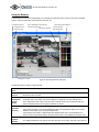
ProSight-SOHO
IP-Surveillance Platform for
Small Office-to-Home Office Businesses
Installation and User Manual
222 Route 59 suite 303 y Suffern, NY 10901 y U.S.A
Phone: (845) 369-6400 y Fax: (845) 369-8711
www.onssi.com
On-Net Surveillance Systems Inc.
On-Net Surveillance Systems ProSight-SOHO Rev 4.0
Installation Guide & Manual
Dear Customer,
With the purchase of On-Net Surveillance Systems Inc (ONSSI) ProSight SOHO you have chosen an extremely
powerful and flexible surveillance solution. ONSSI ProSight SOHO will turn your TCP/IP-based video cameras and
video servers into a sophisticated digital video surveillance system fully controlled from your PC.
ONSSI ProSight SOHO (version 4.0) provides you with these main features:
•
•
•
•
•
•
•
•
•
•
•
•
•
Record and view cameras with up to 30 frames per second (25 for PAL)
Control up to 16 cameras per server
Secure image database with recovery options
Advanced low disk space database handling
Scheduled recording based on time
Flexible screen setup with the Recordings Browser located in a floating window
Advanced motion detection with Exclude Filter for image areas of no interest
Find specific recordings by date/time or event.
Control of PTZ cameras
Time stamped event documentation on print, as AVI or single JPEGs
Receive motion alerts via E-mail
All system messages on screen, in log-file and optionally via E-mail
Remote access to the system through the included Web Server with live images in single view, pan/tilt/zoom,
database playback and database browsing
Page 2 of 26
On-Net Surveillance Systems Inc.
Contents
INSTALLATION GUIDE.............................................................................................................................................4
Introduction ................................................................................................................................................ 4
Before You Install....................................................................................................................................... 5
Step 1: Obtain Device License Keys ......................................................................................................... 5
Step 2: Connect the Devices ..................................................................................................................... 5
Step 3: Install the Software........................................................................................................................ 6
Step 4: Configure for First Time Use ......................................................................................................... 6
PROGRAM HELP ........................................................................................................................................................6
Obtaining Support ...................................................................................................................................... 6
ADMINISTRATOR MANUAL....................................................................................................................................7
Configuring Video Cameras and Video Server Devices............................................................................ 8
Changing Device Settings ......................................................................................................................... 9
Configuring Video Servers.................................................................................................................... 10
Configuring Monitors and User interface Layout ..................................................................................... 10
Setting Image Quality and Recording Conditions.................................................................................... 11
Calibration of Motion Detection................................................................................................................ 13
Defining Motion Detection Exclude Areas ............................................................................................... 15
Setting Up and Using PTZ Preset Positions..............................................Error! Bookmark not defined.
General Settings ...................................................................................................................................... 16
Configuring E-mail Alerting................................................................................................................... 17
Daily Database Archiving...........................................................................Error! Bookmark not defined.
SCHEDULING CAMERA ACTIVITY AND ALERT PERIODS.............................................................................18
MONITOR MANUAL................................................................................................................................................20
The Pan/Tilt/Zoom Panel........................................................................Error! Bookmark not defined.
Using the Browser ................................................................................................................................... 22
Configuration Options........................................................................................................................... 23
APPENDIX A: ADVANCED CAMERA CONTROL WITH SENSORS ..................ERROR! BOOKMARK NOT
DEFINED.
APPENDIX B: USING THE PROSIGHT SOHO WEB SERVER ............................................................................25
Page 3 of 26
On-Net Surveillance Systems Inc.
Installation Guide
Introduction
ONSSI ProSight SOHO consists of five software applications: Administrator, Monitor, Browser, Web Server and
Realtimefeed Server. Each of these applications is described briefly below.
The Administrator application: The administrator of the surveillance installation uses this tool when setting up the
system for the first time use, when adding new cameras and whenever the system configuration needs to be
changed. This tool is also used to configure the screen layout of the Monitor, recording conditions, etc.
The Monitor application: This application is the core of the surveillance system, as well as the main user interface.
The Monitor records and displays live images from the connected cameras.
The Viewer application: This application is used to play back recordings (up to 4 cameras simultaneously), create AVI
files, export and print images.
The Web Server and Realtimefeed Server applications: These two applications make up a powerful Web server that
will enable users to access the surveillance system from a remote site using a Web Browser. Using a Microsoft™
Internet Explorer Web Browser on a remote computer you can view live images from the cameras, control PTZ
cameras, and review recordings. An alarm overview is available to locate the desired event quickly.
Please note
•
Certain features in the Administrator are disabled from editing if the Monitor is running at the same time.
•
In order to achieve the best performance and most reliable operation, it is recommended that you do not use
the surveillance PC for other purposes.
•
The Monitor application and cameras must run to record images. The video surveillance is therefore not
working if the Monitor application is closed!
Page 4 of 26
On-Net Surveillance Systems Inc.
Before You Install
Please be aware of the minimum system requirements.
Minimum Hardware Requirements *)
Up to 50 images/second total
CPU
Up to 400 images/second total
Pentium III, 2.8GHz
SATA disk(s)
Dual Pentium Xeon, 3.6GHz
SATA disk(s)
Size depends on storage needs
Size depends on storage needs
RAM
512 MByte
1 GByte
Video
True color (24 bit)
min. 1024 x 768 pixels
AGP video card
128MB PCIe x16, such as ATI FireGL V3100,
DualVGA or
DVI+VGA
Ethernet 100 Mbit
Ethernet 100 Mbit
HDD
Network
*) Based on 320x240 JPEG images, medium compression.
Software Requirements
OS
Recommended for dual and single processor systems:
- Microsoft Windows 2000 PRO / 2000 Server / XP PRO
Note: It is highly recommended that all available Service Packs are installed for the Operating
System being used!
Protocols, APIs
and Software
- TCP/IP support is required
- Microsoft Internet Explorer 5.5 or newer is required
- DirectX 8.1 or higher required for audio recording
In-compatible
Software
FTP Server: Included in the software (default port 21).
HTTP Server: Included in the software (default port 80).
Realtimefeed Server: Included in the software (default port 9513).
To run other servers on these port numbers it is required to change the port number used by
the ProSight SOHO server.
Step 1: Obtain Device License Keys
Please refer to the ONSSI ProSight SOHO Quick Start Guide for details on how to obtain and import Device License
Keys (DLKs).
Device License Keys are not required to run the Demo version.
Step 2: Connect the Devices
Connect all the devices to your LAN/Ethernet as described in the manuals for the camera devices. Consult these
manuals for more information.
For devices having an integrated Web interface, you can verify that the device is successfully installed on your
network by connecting to it using a standard Web Browser. If you cannot connect using a Web Browser, then
you will not be able connect in ONSSI ProSight SOHO either.
Page 5 of 26
On-Net Surveillance Systems Inc.
Step 3: Install the Software
To make sure you install the most recent version of our software, please check our website www.onssi.com for
updates. Here you can also download the ONSSI ProSight SOHO Quick Start Guide and the latest version of this
User Manual.
Please refer to the ONSSI ProSight SOHO Quick Start Guide for details on how to uninstall any previous version of
the software and how to install the most current version of the ONSSI ProSight SOHO.
The ONSSI ProSight SOHO by default starts up automatically when the PC is started. This functionality can be
disabled in the General Setings window in the Administrator application.
If a demo version of ProSight SOHO was already installed it is necessary to remove the image databases. This
can be done either by uninstalling the demo version (including the databases) or by clearing each camera
database from within the new version of the ProSight SOHO software. Please refer to the section "Setting Image
Quality and Recording Conditions" for more details on this.
Step 4: Configure for First Time Use
Upon successfully installing the ONSSI ProSight SOHO software you will need to add your video camera and video
server devices.
The ONSSI ProSight SOHO Quick Start Guide can guide you through these initial steps, including a basic
configuration of the Monitor screen layout and scheduler setup.
For more advanced customization options, please refer to the Administrator Manual section in this manual.
Program Help
The Administrator, Monitor, and Browser applications have context help for all available functionality.
You obtain help by pressing the question mark icon in the program's active window (or in some windows, the Help
button). The cursor will turn into a “What’s this” cursor and you can now click on the item that you need help with.
Afterwards, click anywhere with the mouse in order to remove the help pop-up window.
Obtaining Support
If you have questions or problems not answered in this manual, please contact your ONSSI Software dealer or visit
the ONSSI Surveillance Support site at www.onssi.com.
Page 6 of 26
On-Net Surveillance Systems Inc.
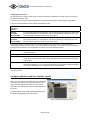
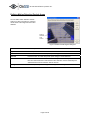
Administrator Manual
The Administrator application is used when setting up
the system for first time use, when new cameras are
added to the system, and whenever the system
configuration needs to be changed. This tool is also
used to configure the screen layout of the Monitor
application, which recording conditions to use, etc. Start
the Administrator from the Program Menu.
In the main dialog box you have the following buttons:
Add Device…
Add new video camera or video server devices to the system. Please refer to the Quick Start
Guide and the more detailed "Configuring Video Cameras and Video Server Devices" section
in this manual for details.
Edit Device…
Edit/update the configuration of an existing device.
Remove Device
Remove an existing device from the system.
Settings…
Set up image quality and recording conditions, etc. for the camera.
See section "Setting Image Quality and Recording Conditions".
Monitor
Manager…
Set up screen layout and screen positions of the cameras, etc.
See section "Configuring Monitors and User Interface Layout".
Scheduler…
Control when cameras are online and when alerts are given.
See the "Scheduling Camera Activity and Alert Periods" section.
General
Settings…
Set up user rights and other system settings. See section "General Settings".
Import DLKs…
Import the DLK file provided by the ONSSI licensing form. Please refer to the Quick Start
Guide for details. Importing the DLK file eliminates the need to enter the DLKs manually!
Page 7 of 26
On-Net Surveillance Systems Inc.
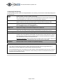
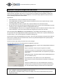
Configuring Video Cameras and Video Server Devices
When pressing the Add Device button In the Administrator the wizard will appear:
First Wizard dialog box:
The video device has this IP-address
on the network:
Enter the IP address of the device on your network
Click the 'Port Setup' button if other
than HTTP port 80 and FTP port 21 is
used
The HTTP and FTP ports used can be changed by clicking the "Port
Setup" button. This is used if more devices share the same IP address
(e.g. behind a router with NAT functionality).
In the vast majority of cases it will not be necessary to change the default
ports.
Second Wizard dialog box:
The password for the video device
administrator account is:
Please enter the password for the video device's administrator account
(sometimes called 'root' or 'admin').
Autodetect Device
For fast detection you can select the video device type. You can also keep
the 'Auto Detect Type' selection and let the system find the device type.
Third Wizard dialog box:
DLK:
Please enter the Device License Key (DLK) for the MAC address. The
DLK will appear automatically if the SLC.dlk file received by E-mail was
imported (See the E-mail for details).
Fourth Wizard dialog box:
Show this name for the video device:
Please enter a name that will help you identify the device later, e.g.
"Entrance Door, "Sales office" etc.
Note that the system does not allow two devices with the same name.
Press the Camera Setup button to
set up camera names and PTZ
devices for this device.
Press the Camera Setup button if changes should be made to the default
camera name (Camera 1). For multi-channel video servers the camera
names are Camera 1, Camera 2, etc.
PTZ devices (PTZ cameras or fixed cameras on PTZ foots) should be
enabled and the COM port and driver selected. For more detailed
information see the sub section “Configuring Video servers" found in the
next section ("Changing Device Settings").
After a device has been successfully added a new device icon will appear in the "Device Manager" window. Press the
"Add Device…" button again in order to set up remaining devices.
Page 8 of 26
On-Net Surveillance Systems Inc.
Changing Device Settings
Changes to HTTP/FTP ports, IP addresses and device/camera names can be done by selecting the device in the
"Device Manager" window and subsequently pressing the "Edit Device…" button.
In the Identify Video Device area the following information is found:
Device Type
The type of device you are using. (The device type can be found automatically if you press the
Detect Device button and the correct IP-address and Device Password have been specified).
Device Name
The name that helps you identifying the device in the software, e.g. "Entrance Door", "Meeting
Room 1" etc. Note that the same name can not be used for more than one device.
Device Serial
Number
The serial number (usually the MAC address) of the device, e.g. 00408c291ba2. The serial
number is usually found on a label on the device (can also be found automatically with the
Detect Device button if the correct IP-address and Device Password have been specified).
Device License
Key
16 characters license key associated with the device, e.g. c5a8ff0c89679490 (See Step 1
"Obtain Device License Keys").
In the Network Settings area the following information is found:
IP-address
The IP address of the device on your network.
Default HTTP port
Select this option if HTTP traffic to the device should go through port 80 at the specified IPaddress.
Deselect this option if a non-standard HTTP port should be used and specify the port in the
field to the left of this checkbox.
Default FTP port
Select this option if FTP traffic to the device should go through port 21 at the specified IPaddress.
Deselect this option if a non-standard FTP port should be used and specify the port in the field
to the left of this checkbox.
Root Password
The password required when logging on to the device using the “root” (sometimes called
"Admin") account.
In the Audio area the following information is found:
Audio Enabled
Available if audio is supported for the device. Select the option to enable audio through the
device. Audio requires DirectX 8.1 or higher.
Page 9 of 26
On-Net Surveillance Systems Inc.
Configuring Video Servers
For Video Servers you need to specify if the connected cameras are Pan/Tilt/Zoom cameras and you can also give
the individual camera a name.
In order to do this, press the Camera Settings button and the Camera Settings for Device dialog box will appear.
In the PTZ Camera Selection area the following information is found:
Some of the
connected
cameras …
Select this option if any of the connected cameras are Pan/Tilt/Zoom cameras.
PTZ type
controlled
through COM1
If you are controlling the PTZ functionality of one or several cameras through the COM1 control
port of the device then you must select the correct PTZ camera type in the list box. If you are
not controlling any devices through this port, select "None".
PTZ type
controlled
through COM2
If you are controlling the PTZ functionality of one or several cameras through the COM2 control
port of the device then you must select the correct PTZ camera type in the list box. If you are
not controlling any devices through this port, select "None".
In the camera list box you will see a line for each camera channel on the Video Server. First line (Camera 1)
corresponds to camera channel 1 and so on. In order to specify the settings for e.g. Camera 1 click once the first line,
it will then become selected. In the configuration area below you have the following options:
Camera Name
Enter a name of the camera for you to remember it by. E.g. a name related to its location, such
as "Main Entrance".
Camera Type
If the camera is a PTZ camera select "Movable", otherwise select "Fixed".
Device Port
Enabled if "Movable" is selected as Camera Type:
Select, which control port on the Video Server, should be used to control the PTZ functionality
of the camera.
Port Address
Enabled if "Movable" is selected as Camera Type. Specify the port address of the camera,
which would normally be 1 or 0. If using daisy chained PTZ cameras the port address identifies
each of them. Please refer to the camera manual for more information.
Pressing the Apply Changes button will show the updated information in the camera list box. Press the OK button
when you are done.
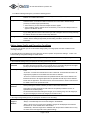
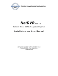
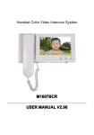
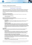
Configuring Monitors and User interface Layout
When you have configured the software for your camera and
video server devices then you need to select which screen
layout the Monitor application should use, and you must
specify where the individual cameras should be displayed on
the screen.
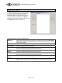
In the Administrator press the Monitor Manager button and
the Monitor Manager dialog box will be shown.
Figure 1: Monitor Manager dialog box
Page 10 of 26
On-Net Surveillance Systems Inc.
In the Monitor Manager dialog box you have the following options:
Layout Size
HotSpot Window
Select how many monitors (i.e. camera windows) you wish to appear on your screen. Select
between 1x1 to 8x8 monitor views.
The Hotspot Window is a secondary camera window that can show an enlarged view of a
selected camera. It can also be used for interactive PTZ control and to browse through
previously recorded images (Quick Browse).
• Select "None" if you don't want the HotSpot window to appear.
• Select "HotSpot" and the desired size of the window if you do want the HotSpot window to
appear in the Monitor window.
Select Camera
Select which camera to show in the selected monitor. You assign the cameras to the monitors
by (a) clicking with the mouse on the monitor you want to assign a camera to and (b) selecting
the desired camera in the Select Camera drop down box.
Settings…
This button will take you directly to the Camera Settings dialog box for the currently selected
camera. See the "Setting Image Quality and Recording Conditions" section for more
information.
Setting Image Quality and Recording Conditions
For each of your cameras you can set the desired image quality, recording speed, and other conditions for the
recording of images.
In the Administrator main dialog's tree-view, select the camera in question and press the "Settings…" button. The
Camera Settings configuration dialog box will be shown.
You can also invoke this dialog box by pressing the Settings… button in the Monitor Manager dialog box.
In the Framerate Settings area you specify the recording speed of the camera:
Desired
Framerate
Specify the desired recording speed by entering the number of frames you wish to retrieve from
the device each second, minute or hour. This will give you a recording range from 24 images
per day up to 30 images per second (25 images per second for PAL).
Enable Speedup
Select this option if you want to increase the framerate on motion detection and/or an external
event.
“On motion”: Increase the framerate when motion is detected. The framerate will revert to its
original (lower) speed two seconds after the last motion is detected.
“On event”: increase the framerate when the specified external Start event is detected. The
framerate will revert to its original speed when the specified external Stop event is detected.
Please refer to Appendix A: ”Advanced Camera Control with Sensors” section of this manual
for details of how to set up external events.
Desired speedup
framerate
When the Enable Speedup option is selected, the desired (higher) recording speed is specified
here by entering the number of frames you wish to retrieve from the device.
This higher recording speed will be used whenever the speedup conditions are met, as
specified under Enable Speedup.
As with the desired framerate setting this will give you a recording range from 24 images per
day up to 30 images per second (25 images per second for PAL).
In the Image Storage Settings area you specify the conditions for the recording:
When to store
images in
database
Specify when to store the received images for this camera in the database.
“Always”: Unconditionally store all received images in the database.
“Never”: Never store any images in the database. Images are still displayed in the Monitor
window but can not be viewed via the web interface.
“Conditionally”: Store the images to the database when the specified conditions are met only.
On motion: Store all images with motion (default setting)
Page 11 of 26
On-Net Surveillance Systems Inc.
On Event: Store all images (regardless of motion) when the defined Start event occurs until the
defined stop event occurs.
Both conditions can be used alone or combined. When both options are ticked images are
stored in the database if just one of the conditions is met.
Pre/Post buffer
The number of seconds to store before and after the conditions for storage is met.
In the Database Settings area you specify how many images you want to store in your image database and the
location of the image database files on your disk:
Max. images in
database
Select this option to limit the image database for the camera to a maximum size. When the
maximum number of images has been recorded, the oldest image in the camera database will
be overwritten automatically, each time a new image is received. The maximum size that can
be specified is 600.000 images.
Delete images
older than
Select this option if you want the recordings in your image database for the camera to be
limited by age. If this option is selected the images will automatically be deleted when they are
older than the specified number of minutes, hours or days. Please note that you will not be
able to store more than 600.000 images regardless what maximum age has been
specified.
Database Path
Specify the main directory on your disk to keep the image database. A sub directory for this
camera will be created by the system, but the main directory you specify must exist; it will not
be created automatically.
To achieve the best performance, it is strongly recommended that you specify a location on a
local hard disk, not on a network drive.
Browse path (…)
Press this button if you wish to browse for the database path directory.
Clear Database…
Press this button if you wish to delete all images recorded for this camera. Caution: All your
recordings for this camera will be permanently lost (This does not include archived databases).
Delete Audio
older than
Select for how long audio recordings should be kept in number of minutes, hours or days.
When older than specified, sound recordings will be deleted unless they have been archived.
In Case Of
Database
failure…
Audio archiving is done automatically if the image database archiving functionality is activated.
In case of a database failure, the following image database recovery options are available.
“Repair, Scan, delete if fails”: Repair, means the system makes an attempt to fix the corrupt
database by examining the main database file, repairs are done in seconds. Scan, is a more in
depth repair of the database, a large database can take hours to complete.
Please note that no images can be recorded while the database repair function is running.
“Repair, delete if fails”: Fast repair will be attempted, if fast repair fails (very rare) the database
will be deleted.
“Repair, archive if fails”: Same as above, except the database will be archived if the repair fails.
“Delete, no repair”: No repairs are attempted, the database is deleted.
“Archive, no repair”: Database is archived, no repair is performed.
The first time the archived database is opened in the Browser the database repair function will
start repair of this specific database.
Please note that this option is available only if archiving has been set up for this camera.
Please refer to the chapter Daily Database Archiving in this manual for details.
In the case recordings get bigger than expected or the available disk space is suddenly reduced in another way,
an advanced database re-sizing procedure will automatically take place:
If archived databases are present on the disk containing the current database the oldest archive for all cameras
on that disk will be deleted. If no archives are present the database size of the current databases will be reduced,
so that a percentage of the oldest recordings will be deleted and each database size will temporarily be limited to
its new size.
Page 12 of 26
On-Net Surveillance Systems Inc.
You will be informed on the screen, in the log-files and optionally through E-mail (if setup).
When the Monitor application is restarted the old database sizes will be used. It is therefore up to the user to
adopt the new sizes or solve the disk size problem in another way.
In the Camera Monitor Setup area you specify how your camera is displayed in the Monitor:
Show Motion
Select this option if you want the detected motion to appear highlighted in the image. If
selected, the areas of the image with motion will be colored with the selected motion color.
Clicking the "Motion Color…" button in the "Motion Detection Settings" area will allow you to
change the motion color used.
Show Regions
Select this option if you want the areas in which motion detection has been excluded (disabled)
to appear highlighted in the image. If selected, the areas will be colored with the selected
region color.
Clicking the "Region Color…" button in the "Exclude Regions Settings" area will allow you to
change the region color used.
Update on motion
only
Select this option if you only want the camera to be updated on your screen when motion has
been detected. Enabling this option greatly reduces the workload of the PC. It is therefore
recommended that you select this option if the PC runs primarily as a server, serving clients
through the built-in Web Interface.
Note: It is possible to disable screen updating completely in the General Settings menu.
In the Motion Detection Settings area you have access to setting up motion detection for the camera:
Motion
Detection…
Press this button in order to calibrate the motion detection. Please refer to the Calibration of
Motion Detection section for details.
Motion Color…
Press this button to select a new motion color. Please refer to the "Show Motion" option in the
Camera Monitor Setup section.
In the Exclude Regions Settings area you have access to setting up regions for the camera that should be excluded
from motion detection:
Exclude
Regions…
Press this button in order to specify if certain areas of the images should be excluded from the
motion detection. Please refer to the "Defining Motion Detection Exclude Areas" section for
details.
Region Color…
Press this button to select a new region color. Please refer to the "Show Regions" option in the
Camera Monitor Setup section.
In the bottom of the Camera Settings dialog box two buttons are found:
Image Quality…
Activates the "Configure Device" dialog box. Here the camera image quality, including image
size and compression, can be set up. A preview image can be shown with the current selected
settings.
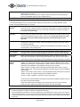
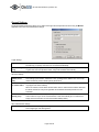
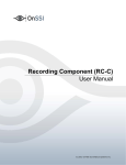
Calibration of Motion Detection
The motion detection system may control (a) when images are saved to disk and (b) when alarms are generated, and
it is therefore a vital element of the system.
Motion detection needs to be calibrated carefully otherwise it will not function properly. Do this as described below.
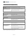
It is recommended that you set up the
image quality to be used, and that any
regions excluded from motion detection (if
Detected
motion is
shown with the
selected motion
color
Page 13 of 26
Motion Level
On-Net Surveillance Systems Inc.
any) are defined before you calibrate the
motion detection.
Motion Level
Indicator
Indicates the current level of detected motion in the image. The indicator is green when the
level is below the threshold and will turn red when the threshold is exceeded.
Alarm Threshold
Indicator
Indicates the selected motion alarm threshold. A motion alarm will be generated when the
motion level goes beyond the threshold.
Noise Sensitivity
Slider to adjust the noise sensitivity level of individual picture elements (pixels). The noise
sensitivity level controls when the change in light intensity and color (light change) of individual
pixel should be considered noise (i.e. an insignificant change) and when it should be
considered motion (i.e. a significant change). In the live updating camera image you will see the
pixels in which motion has been detected marked with the selected motion color (which is green
by default). In order to understand how it works, try to drag the slider to position "high" and
watch how the whole camera image will turn green.Drag the slide bar back to the optimal
position, where only the pixels affected by significant light changes are marked with the motion
color.
Motion Sensitivity
Slider to adjust the motion sensitivity. The motion sensitivity controls the alarm threshold and
thereby determines the minimum size of an object that will generate an alarm.
Drag the slider until the alarm threshold indicator is at the optimal position.
Trees and bushes outdoors and plants indoors may generate undesired noise, you may find that you can define
motion detection exclude areas to eliminate this noise.
Some video cameras generate undesired noise at poor light conditions. In order not to generate undesired
alarms, you may find that you need to reduce the noise sensitivity or to improve the light condition.
Page 14 of 26
On-Net Surveillance Systems Inc.
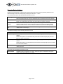
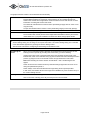
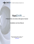
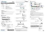
Defining Motion Detection Exclude Areas
You can define motion detection exclude
areas if you wish to exclude (i.e. mask out)
certain areas of the image from the motion
detection.
.
Squares
excluded
from
motion
Figure 3: Define Exclude Regions dialog box
Left mouse button
Exclude square from motion detection.
Right mouse button
Include square in motion detection.
Set All
Press this button to exclude all squares (whole image) from motion detection.
Clear All
Press this button to include all squares (whole image) in motion detection.
Auto
Press this button to make the software detect noisy areas automatically and exclude
them from motion detection. Note that the motion detection must be reasonably well
calibrated before this auto detection feature will work.
Show grid
Select this option if you wish the grid lines to appear in the image.
Page 15 of 26
On-Net Surveillance Systems Inc.
General Settings
The General Settings dialog box allows you to define which rights the user/operator has when using the Monitor
application and to set other administrative settings.
Logfile Settings:
Logfile Path
Specify in which directory on your disk to keep system log files.
The directory you specify must exist; it is not created automatically.
Number of days
to log
Specify how many days you want to store the log files. A new log file will be created each day.
Log files older than the specified number of days will be deleted automatically.
Advanced settings:
Disable Screen
Update (server
mde)
Select this option if the Monitor screen is not used on a daily basis by an operator but only used
when setting up the software. All Monitor screen updating will be disabled. This can free up
resources that may result in better system performance.
Don't send E-mail
on camera failure
Select this option to disable sending of an E-mail whenever a camera failure occurs (This will
only happen if E-mail is enabled).
When not selected, camera failure E-mails will be sent if E-mail has been enabled. Note that
this will be carried out at any time regardless of scheduled E-mail alert periods set in the
Scheduler.
Add Monitor to
Startup group
Makes sure the Monitor is always started up when the PC is booted.
Uncheck this box if you do not want the Monitor to start automatically (it is not sufficient to
simply remove the Monitor icon from the Windows Startup folder).
Other administrative settings:
E-mail Settings…
Press this button to change the settings for E-mail alerting.
See Configuring E-mail Alerting below.
Page 16 of 26
On-Net Surveillance Systems Inc.
Configuring E-mail Alerting
The E-mail alerting system needs to be configured before it can be used; you do this in the E-mail Setup dialog box in
the following way:
Enable
E-mail
Select this option in order to enable E-mail alerting.
Advanced…
If Simple MAPI mail client is not available, it is possible to configure SMTP E-mailing instead.
SMTP can also be used if the mail client requires confirmation before sending E-mails.
Recipient(s)
Specify the E-mail address of one or more recipients. Use a semicolon (;) to separate the
addresses if more than one recipient is specified.
E.g.: [email protected]; [email protected]
Subject Text
Specify the text string to be used as the subject for the E-mails sent.
Message Text
Specify the text string to be used as the message (body) for the E-mails sent. The name of the
device and camera that generated the alarm will automatically be appended to the text.
Include Image
Select this option if you want the image that generated the alert to be attached to the mail.
Time btw. Mails…
Specify the minimum number of minutes between the alert E-mails for the individual camera or
0 (zero) if each motion detection should result in an alert E-mail. A motion alert from a camera
will not generate an alert E-mail if the minimum number of minutes specified has not elapsed
since the last alert E-mail for the camera was sent.
Note: Camera failures and system failures will automatically be sent through E-mail if this has
not been disabled under "Advanced" in the "General settings" dialog box
Background information: During a longer period of constant motion a high number of alarms will
be generated; it may not be desirable that an alert E-mail is sent for every alarm.
Test button
Press this button to send a test mail to the specified recipient(s).
How do I configure my backup program?
If you want an external backup program to make a tape backup of the daily archived image database for a
camera then you should configure it to make a backup of the backup directory.
It is recommended that you do not schedule it to make a backup of the image database directory itself, since this
may cause sharing violations and other malfunctions. Note also that you should not schedule the backup job to
overlap the time of the daily archiving.
Page 17 of 26
On-Net Surveillance Systems Inc.
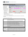
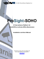
Scheduling Camera Activity and Alert Periods
In this section you can read
about how to control
important functions of the
system automatically
through the built-in
Scheduler. The Scheduler
uses a one-week-calendar
and allows you to control:
•
Starting and stopping
cameras on time
•
Starting and stopping
cameras on events
(external sensors)
•
Alerting through E-mail
and/or sound on motion detection.
•
Figure 4: Scheduler dialog box
Motion alerts to certain periods of the day/week.
The Scheduler is activated in the Administrator application by pressing the Scheduler button. The following dialog
box will appear:
The following options and buttons are available:
Mode
The mode selection controls if time periods are added or removed when clicking and dragging
the mouse in the graphical window.
Set: Add/replace period for functionality (Online, E-mail and Sound) currently selected.
Clear: Remove period for functionality (Online, E-mail and Sound) currently selected.
Online
This option should be checked if clicking and dragging in the graphical window should affect
(Mode: Add/Clear) the Online periods for the selected camera.
E-mail
This option should be checked if clicking and dragging in the graphical window should affect
(Mode: Add/Clear) the E-mail alert periods for the selected camera.
Sound
This option should be checked if clicking and dragging in the graphical window should affect
(Mode: Add/Clear) the Sound alert periods for the selected camera.
Note: Used for audible alarm via PC soundcard, NOT for scheduling audio recording!
Camera
Select in the list among the installed cameras. The Scheduler only operates on the currently
selected camera.
Copy Schedule
Make a copy of the current schedule in order to transfer the same schedule to another camera.
Paste Schedule
Paste the copied (Copy Schedule) schedule setup to the currently selected camera. The same
schedule can be pasted to more cameras by selecting each camera from the Camera listbox.
Important: Be careful when pasting because schedules are overwritten without any warning.
Copy and Paste
Schedule to all
Paste the copied (Copy Schedule) schedule setup to all cameras.
Important: Be careful when pasting because schedules are overwritten without any warning.
Page 18 of 26
On-Net Surveillance Systems Inc.
The graphical window contains a lot of information and functionality:
Online Bar
Shows in which periods during the week the camera is active (i.e. transferring images to the
ProSight SOHO software for processing). Camera activity can be controlled through time
and/or events. Please refer to Appendix A "Advanced Camera Control with Sensors" for more
information on working with sensors and events.
The Yellow bar indicates that the camera is active (transmitting images) when an event occurs
only (On Event).
A Purple bar indicates that the camera is active (transmitting images) continuously (Always).
E-mail Bar
Shows in which periods during the week E-mails should be sent when motion is detected.
Sound Bar
Shows in which periods during the week sound alerts should be given when motion is detected.
The sound file used must be placed in the ProSight SOHO Surveillance directory and must be
named alarm.wav. If you prefer a different sound than the default, simply replace the file.
Before using the E-mail Alerting System you need to configure them by pressing the associated button in the
General Settings dialog box and filling out the required information. The General Settings dialog box is activated
in the Administrator application by pressing the General Settings button.
See the earlier sub-sections "Configuring E-mail Alerting" for information on this.
Click & drag the
mouse
When you have selected the Mode (Set/Clear) and selected which functions (Online, E-mail,
Sound) you wish to operate (by checking their check boxes), you do the following:
(a) Move the mouse cursor to the desired start time in the scheduler window (pencil cursor
indicates Set, eraser cursor indicates Clear), (b) click the left mouse button and keep the button
pressed, (c) drag the cursor to the desired end time and (d) release the mouse button.
Note: When including the "Online" function and the Mode = "Set" a small dialog box will
appear:
Select "On Event" if the camera should only start transmitting images when the event occurs
during the specified time period, or
Select "Always" if the camera should transmit images during the time period specified.
In both cases, the software will store the images in the database only if the conditions set up in
the Camera Settings are met.
Weekdays
Click on the name of a weekday (in the week overview) to zoom into that day.
Click on the name of the day (in the day overview) to zoom out to the week.
Page 19 of 26
On-Net Surveillance Systems Inc.
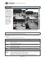
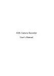
Monitor Manual
The Monitor application
forms the core of the
surveillance system; it is
responsible for all the
practical work during the
normal operation of the
system. Besides forming
the main user interface,
the Monitor application
starts and stops the
cameras, acquires the
images, displays the
images on screen,
detects if motion has
occurred, saves the
images in the image
databases, sends
alarms, etc.
Figure 5: Main window of the ProSight SOHO Monitor application. Here shown with four
monitor windows, each showing the image stream of the associated camera
The surveillance system is only active when the Monitor application is running. If you close the application you
will not be recording images and alert-messages will not be sent.
Start the Monitor from the Program Menu or from the shortcut on the desktop if you chose to make a link during the
installation.
In the main window you have the following buttons (from the top):
Minimize
Press the leftmost button of the three small buttons in order to minimize the Monitor window.
Help
Press the middle button of the three small buttons to get on-line help for the next item you click on.
Exit
Pressing the rightmost button of the three small buttons will close the Monitor application. You will
be asked to confirm this.
Note that this will stop all recordings.
Recordings
Press this button to start the Browser and review your recordings. Please see section "Using the
Recordings Browser" for details.
Start / Stop
Press this button to start or stop the camera in the selected monitor. The button is only enabled
when manual mode is activated.
Start All
Press this button to start all cameras. The button is only enabled when manual mode is activated.
Stop All
Press this button to stop all cameras. The button is only enabled when manual mode is activated.
Manual
(Schedule
Override)
Switch between scheduler controlled mode and manual mode. In scheduler controlled mode the
scheduler is responsible for starting and stopping the cameras. In manual mode the cameras can be
started and stopped manually using the start and stop buttons.
The system is in manual mode when the button is pushed in.
Note that when in manual mode all scheduled camera start/stop, PTZ patrolling and
Page 20 of 26
On-Net Surveillance Systems Inc.
automatic camera reconnection is disabled!
Admin Login
Press this button to gain administrator rights, and thereby removing the restricted rights a normal
user may have. Applicable only if the standard user's rights have been configured to be restricted.
Quick
Browse (QB)
Switch between on-line mode and quick browsing mode in the HotSpot window. The HotSpot
window is in quick browsing mode when the button is pushed in.
QB Arrows
Use these two buttons to Quick Browse backward or forward in recordings for the camera shown in
the HotSpot window.
Mute
Select this option to mute audio in the monitor application.
Exit
Press this button to stop the Monitor application and thereby stop all camera recording. You will be
asked to confirm this.
When you start the Monitor application it will start the cameras automatically if you have specified them as
"Online" in the Scheduler. You can disable and overrule the Scheduler by pressing the "Manual" button.
When in “Manual” mode the cameras can be started manually one by one by pressing the "Start" button or all
cameras can be started simultaneously by pressing the "Start All" button.
Note: For normal operation cameras should be scheduled and not left in manual mode!
The HotSpot window shows an enlarged view of the selected monitor window. In order to show another monitor
window in the HotSpot window, you must select the new monitor window by clicking on it with the mouse.
Page 21 of 26
On-Net Surveillance Systems Inc.
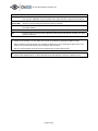
Using the Browser
In the Browser you can review and playback your recordings of images and sound, printout or export the individual
images, create AVI video files, export sound as wave files, etc.
Configuration menus
Configuration and
action shortcuts
User configurable monitor display
with activity indicators
Recordings Timeline
Configuration window
Direct Date/Time selections
Current playback
date/time display
Figure 6: Recordings Browser dialog box.
The Browser window consists of eight elements:
Configuration
Menus
Menus for Browser configuration and functionality activation.
Configuration
Shortcuts
Shortcuts to selected Configuration Menu functions. When holding the mouse pointer over an icon
the shortcut name is shown.
User
configurable
monitor
display
Each monitor can be configured to display any video (and audio) source via the Tools, Database
Information menu. The layout of the monitor display is configured in the File, Settings menu.
Direct
Date/Time
Selection
Jump directly to a specific date and/or time (15 minutes intervals).
In the status bar for each camera, the name of the camera and the motion detection (red) and
image in database without motion (green) indicators are shown.
If the content is stored in an archived database located in the default path relative to the current
database, the archives can be accessed transparently.
If the archives are located in a different path than default relative to the current database, the
archives must be opened manually by using the browse button in the Database Information menu.
Current
playback
date/time
Here the date and time currently viewed on the monitors is displayed.
The displayed date/time is the system (PC) time at the time of recording. This time is also referred
Page 22 of 26
On-Net Surveillance Systems Inc.
display
to as a timestamp.
Recordings
Timeline
The Recordings Timeline shows the database information for each camera monitor position.
The information is distinguished by colors:
Grey: No images are stored for this date/time.
Green: Images with no motion are stored for this data/time.
Red: Images with motion are stored for this date/time.
The time span and direction of the timeline is configured from the File, Settings menu.
Configuration
Window
Here the currently selected configuration/action window is displayed.
Playback
Controls
The Playback Control Panel is used when playing back recordings.
The Navigation Keys are used to jump to the previous/next image, motion sequence, and database
end for the currently selected camera.
Use the Play Reverse, Stop, and Play Forward buttons to control playback start/stop and directions.
The Cue-Bar can be used to speed up and slow down the playback speed.
Configuration Options
The following functions are available from the Configuration Menus:
File Menu
Settings*): Activates the Monitor/Timeline Settings window.
Monitor View: Set up the monitor layout (1 or 4monitors) and whether the monitors should be
displayed in their original height/width ratio or stretched to fit the monitor windows.
Timeline: Set up the time span of the Recordings Timeline window and whether the timeline
has the oldest (default) or the newest recordings at the top of the Timeline.
Single View*): View only a single camera in the Browser
(Alternatively double-click on an image to switch mode).
Multi View*): View multiple cameras in the Browser simultaneously
(Alternatively double-click on an image to switch mode).
Exit: Close the Browser window.
View Menu
Add to Views: Store the current monitor view as a bookmark.
The bookmarks are listed in the bottom of the menu.
Organize Views: Rename and delete predefined views.
Tools Menu
Database Information*): Set up the video/audio for each monitor.
Click on a monitor position, then select the desired video and audio source for this monitor
position.
If the source is located in an archive stored on a non-default position, or is an exported
database, the content needs to be located manually using the browser (…) buttons.
Motion View*): View the horizontal recordings timeline for the selected camera monitor position.
Alarm Overview*): View the alarm list for the selected monitor position. Jump to an alarm date/time
by selecting it in the list.
Image Controls*): Post-recording image presentation.
PTZ digitally in the image shown at the selected monitor position by using the +/- and arrow
buttons.
Select the “smooth image” option to digitally enhance the image.
Select the 1:1 option to force the Browser to view the selected in original size and height/width
ratio. If the monitor position window is smaller than the image, the zoom in/out and navigation
buttons can be used to navigate in the image.
Tools Menu
(Continued)
Export*): Export database content.
Selecting the desired audio/video feed(s), as well as the desired date and time start/stop
Page 23 of 26
On-Net Surveillance Systems Inc.
intervals to export.
To export all video/audio feeds currently viewed, choose the “Current Video Feed(s)” and
“Current Audio Feed(s)” options.
Next, choose which format to export to:
AVI File: export to motion picture AVI format with audio
JPG/WAV Files: export as single JPG images with audio in separate WAV format
files.
Click NEXT, then choose where to place the exported file(s), and select the export options (if
any) desired:
Timestamp: Include system timestamp on JPG/AVI exports.
Half/Full Framerate: Select whether to include all (full) or every other (half) image
when creating AVI files. Half Framerate may be desirable to avoid very large files
when using high recording speeds.
Codec: Selected the codec (coder/decoder) to use when creating AVI files. If in
doubt, Indeo® Video 5.10 or Microsoft Video 1 are good choices as they will work
on most computers.
Print*): Print out the selected camera image with comments.
Help*): Content specific help tool.
*) This function can also be accessed directly by clicking on the appropriate Configuration and Action shortcut.
Page 24 of 26
On-Net Surveillance Systems Inc.
Appendix B: Using the ProSight SOHO Web Server
ProSight SOHO Surveillance includes a powerful web server that enables access to the image database from a
remote computer. Through the web server you can get access to live images as well as playback recordings and
browse the image databases (including archived databases in the Archives folder). Before the web server can be
used the following requirements must be fulfilled.
Requirements:
•
Internet Explorer 5.0 or above is installed on the remote computer.
•
The ProSight SOHO Surveillance computer should be reachable from the remote computer through a TCP/IP
connection (LAN, modem or Internet).
•
The ProSight SOHO Surveillance computer has a unique IP-address on the LAN and/or Internet.
•
No other web server using the same http port (default port 80) must be running on the ProSight SOHO computer.
The http port can be changed from within the ProSight SOHO Web server.
•
The Live Feed Server uses port 9513. If changed the html pages needs to be edited to reflect this change. Look
for the "RTFeed.port = 9513;" line in each html file and change the port number to the new value.
Open the ProSight SOHO Web Server and Live Feed Server on the ProSight SOHO Surveillance computer. You
can open them from the ProSight SOHO Surveillance group (Start menu), if these were not opened automatically at
computer startup, i.e. with a shortcut placed in the Windows Startup group.
The two servers need to be started before they are active. This can be done manually by clicking the Server Start for
both servers. If AutoStart have been selected chosen for both, they will automatically start when opened (default).
The options in the web server are:
HTTP Port: Here the port used by the HTTP server can be changed.
Auto Start: Start up the service automatically when the application I launched.
Log Activity to File: Maintain a log file in the ProSight SOHO Surveillance
installation directory
Days to log: Number of days to keep the log before it is deleted.
Timeout for connection: If a client has been inactive (not requested any
new information) for the specified duration he is required to log in again to
retrieve data.
Realtimefeed quality: The default quality used by the Realtimefeed server
(can be overridden by user).
User administration: Three options exist for user administration:
Allow anonymous access: No passwords are required for accessing the
server.
Access for predefined users only: Username/password is required to
access the server. All users have access to all options and all cameras.
The user administration dialog is accessed via the User Setup button.
The three quality levels of the Realtimefeed server (live and play back) can be changed in the Windows registry:
HKEY_CURRENT_USER\Software\ONSSI\Surveillance\General.
"RT High Quality", "RT Medium Quality" and "RT Low Quality" can be set to a value between 0-100, with 100
being the best quality.
Page 25 of 26
On-Net Surveillance Systems Inc.
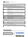
Connecting to the ProSight SOHO Web server interface.
When a user has been added the user should be able to connect to the ProSight SOHO Surveillance system from a
remote computer.
1.
Start the Internet browser on the remote computer.
2.
Enter the IP-address of the ProSight SOHO Surveillance computer in the browser address box. Add the http port
number after the IP-address if another port than port 80 (default) is used. A colon should separate the IP-address
and port number. Now connect to the computer.
3.
A log-in web page will be shown if the connection has been established successfully. Enter the username and
password and select ActiveX support if you are interested in playback or live images. Press the Login button.
4.
You are now connected to the ProSight SOHO Web Server, and the last retrieved image from monitor 1 will be
shown.
You can now:
•
•
•
Change between the different cameras by selecting the camera in the graphic object (Single View - Select
Camera). Move the cursor over the object (Monitor layout) and click when the desired camera is found. The
camera name appears below.
Search for images by using the Image, Motion, Sequence, End, Overview and Alarms forward/backward
functions.
Search for images by date/time by using the Goto function.
•
Press the Playback button and press the Play button below the image to start playback from the current position
in the database. Select between the Low, Medium and High user-defined image qualities from the drop-down
box.
•
Press the Live button and press the Play button below the image to start the live image stream. Cameras defined
as PTZ cameras can be PTZ controlled. PTZ buttons will appear automatically. Select between the Low, Medium
and High user-defined image qualities from the drop-down box.
Note that the camera must be online in the Monitor application in order to establish a live connection to
the camera!
•
Print current image (Still) by pressing the Print button.
•
Click Quad View and select a Quad View to view four cameras live on the same page. Start by selecting the four
cameras from the list boxes below the four monitors and Press the OK button to start the live stream. A total of
ten quad views can be saved. Save a Quad View by pressing the Save Setup button in the top of the Quad View.
You can change the name of the Quad View to the left of the Save Setup button.
•
Press the Help button of the web page in order to get a full functionality description of the different possibilities
that you have.
Page 26 of 26