1
OWNER’S MANUAL
Thank you, and congratulations on your choice of the Roland V-Synth.
Before using this unit, carefully read the sections entitled: “IMPORTANT SAFETY
INSTRUCTIONS” (Owner’s Manual p. 2), “USING THE UNIT SAFELY” (Owner’s
Manual p. 3), and “IMPORTANT NOTES” (Owner’s Manual p. 4). These sections
provide important information concerning the proper operation of the unit.
Additionally, in order to feel assured that you have gained a good grasp of every
feature provided by your new unit, the Quick Start, Owner’s Manual, and Sound
List should be read in their entirety. These manuals should be saved and kept on
hand as a convenient reference.
*
*
*
*
*
Microsoft and Windows are registered trademarks of Microsoft Corporation.
Windows® is known officially as: “Microsoft® Windows® operating system.”
Macintosh are registered trademark of Apple Computer, Inc.
MacOS is a trademark of Apple Computer, Inc.
All product names mentioned in this document are trademarks or registered trademarks of their respective owners.
Copyright © 2002 ROLAND CORPORATION
All rights reserved. No part of this publication may be reproduced in any form
without the written permission of ROLAND CORPORATION.
CAUTION
RISK OF ELECTRIC SHOCK
DO NOT OPEN
ATTENTION: RISQUE DE CHOC ELECTRIQUE NE PAS OUVRIR
CAUTION: TO REDUCE THE RISK OF ELECTRIC SHOCK,
DO NOT REMOVE COVER (OR BACK).
NO USER-SERVICEABLE PARTS INSIDE.
REFER SERVICING TO QUALIFIED SERVICE PERSONNEL.
The lightning flash with arrowhead symbol, within an
equilateral triangle, is intended to alert the user to the
presence of uninsulated “dangerous voltage” within the
product’s enclosure that may be of sufficient magnitude to
constitute a risk of electric shock to persons.
The exclamation point within an equilateral triangle is
intended to alert the user to the presence of important
operating and maintenance (servicing) instructions in the
literature accompanying the product.
INSTRUCTIONS PERTAINING TO A RISK OF FIRE, ELECTRIC SHOCK, OR INJURY TO PERSONS.
IMPORTANT SAFETY INSTRUCTIONS
SAVE THESE INSTRUCTIONS
WARNING - When using electric products, basic precautions should always be followed, including the following:
1.
2.
3.
4.
5.
6.
7.
8.
9.
Read these instructions.
Keep these instructions.
Heed all warnings.
Follow all instructions.
Do not use this apparatus near water.
Clean only with a dry cloth.
Do not block any of the ventilation openings. Install in
accordance with the manufacturers instructions.
Do not install near any heat sources such as radiators,
heat registers, stoves, or other apparatus (including
amplifiers) that produce heat.
Do not defeat the safety purpose of the polarized or
grounding-type plug. A polarized plug has two blades with
one wider than the other. A grounding type plug has two
blades and a third grounding prong. The wide blade or the
third prong are provided for your safety. When the provided
plug does not fit into your outlet, consult an electrician for
replacement of the obsolete outlet.
10. Protect the power cord from being walked on or pinched
particularly at plugs, convenience receptacles, and the
point where they exit from the apparatus.
11. Only use attachments/accessories specified by the
manufacturer.
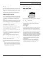
12. Never use with a cart, stand, tripod, bracket,
or table except as specified by the
manufacturer, or sold with the apparatus.
When a cart is used, use caution when
moving the cart/apparatus combination to
avoid injury from tip-over.
13. Unplug this apparatus during lightning storms or when
unused for long periods of time.
14. Refer all servicing to qualified service personnel. Servicing
is required when the apparatus has been damaged in any
way, such as power-supply cord or plug is damaged, liquid
has been spilled or objects have fallen into the apparatus,
the apparatus has been exposed to rain or moisture, does
not operate normally, or has been dropped.
For the U.K.
WARNING:
THIS APPARATUS MUST BE EARTHED
IMPORTANT: THE WIRES IN THIS MAINS LEAD ARE COLOURED IN ACCORDANCE WITH THE FOLLOWING CODE.
GREEN-AND-YELLOW: EARTH, BLUE: NEUTRAL, BROWN: LIVE
As the colours of the wires in the mains lead of this apparatus may not correspond with the coloured markings identifying
the terminals in your plug, proceed as follows:
The wire which is coloured GREEN-AND-YELLOW must be connected to the terminal in the plug which is marked by the
letter E or by the safety earth symbol or coloured GREEN or GREEN-AND-YELLOW.
The wire which is coloured BLUE must be connected to the terminal which is marked with the letter N or coloured BLACK.
The wire which is coloured BROWN must be connected to the terminal which is marked with the letter L or coloured RED.
2
USING THE UNIT SAFELY
The
symbol alerts the user to important instructions
or warnings.The specific meaning of the symbol is
determined by the design contained within the
triangle. In the case of the symbol at left, it is used for
general cautions, warnings, or alerts to danger.
Used for instructions intended to alert
the user to the risk of death or severe
injury should the unit be used
improperly.
Used for instructions intended to alert
the user to the risk of injury or material
damage should the unit be used
improperly.
* Material damage refers
other adverse effects
respect to the home
furnishings, as well
animals or pets.
The
symbol alerts the user to items that must never
be carried out (are forbidden). The specific thing that
must not be done is indicated by the design contained
within the circle. In the case of the symbol at left, it
means that the unit must never be disassembled.
to damage or
caused with
and all its
to domestic
The ● symbol alerts the user to things that must be
carried out. The specific thing that must be done is
indicated by the design contained within the circle. In
the case of the symbol at left, it means that the powercord plug must be unplugged from the outlet.
001
008e
• Before using this unit, make sure to read the instructions
below, and the Owner’s Manual.
• Use only the attached power-supply cord.
........................................................................................................................
002a
• Do not open or perform any internal modifications on the
unit.
........................................................................................................................
003
• Do not attempt to repair the unit, or replace parts within it
(except when this manual provides specific instructions
directing you to do so). Refer all servicing to your retailer,
the nearest Roland Service Center, or an authorized
Roland distributor, as listed on the “Information” page.
..........................................................................................................
004
• Never use or store the unit in places that are:
• Subject to temperature extremes (e.g., direct sunlight
in an enclosed vehicle, near a heating duct, on top of
heat-generating equipment); or are
• Damp (e.g., baths, washrooms, on wet floors); or are
• Humid; or are
• Exposed to rain; or are
• Dusty; or are
• Subject to high levels of vibration.
........................................................................................................................
005
• This unit should be used only with a rack or stand that is
recommended by Roland.
........................................................................................................................
006
• When using the unit with a rack or stand recommended
by Roland, the rack or stand must be carefully placed so it
is level and sure to remain stable. If not using a rack or
stand, you still need to make sure that any location you
choose for placing the unit provides a level surface that
will properly support the unit, and keep it from wobbling.
........................................................................................................................
008a
• The unit should be connected to a power supply only of
the type described in the operating instructions, or as
marked on the unit.
........................................................................................................................
........................................................................................................................
009
• Do not excessively twist or bend the power cord, nor place
heavy objects on it. Doing so can damage the cord,
producing severed elements and short circuits. Damaged
cords are fire and shock hazards!
........................................................................................................................
010
• This unit, either alone or in combination with an amplifier
and headphones or speakers, may be capable of
producing sound levels that could cause permanent
hearing loss. Do not operate for a long period of time at a
high volume level, or at a level that is uncomfortable. If
you experience any hearing loss or ringing in the ears, you
should immediately stop using the unit, and consult an
audiologist.
........................................................................................................................
011
• Do not allow any objects (e.g., flammable material, coins,
pins); or liquids of any kind (water, soft drinks, etc.) to
penetrate the unit.
........................................................................................................................
013
• In households with small children, an adult should
provide supervision until the child is capable of following
all the rules essential for the safe operation of the unit.
........................................................................................................................
014
• Protect the unit from strong impact.
(Do not drop it!)
........................................................................................................................
015
• Do not force the unit’s power-supply cord to share an
outlet with an unreasonable number of other devices. Be
especially careful when using extension cords—the total
power used by all devices you have connected to the
extension cord’s outlet must never exceed the power
rating (watts/amperes) for the extension cord. Excessive
loads can cause the insulation on the cord to heat up and
eventually melt through.
........................................................................................................................
3
USING THE UNIT SAFELY
016
104
• Before using the unit in a foreign country, consult with
your retailer, the nearest Roland Service Center, or an
authorized Roland distributor, as listed on the “Information” page.
........................................................................................................................
• Try to prevent cords and cables from becoming entangled.
Also, all cords and cables should be placed so they are out
of the reach of children.
........................................................................................................................
106
023
• Never climb on top of, nor place heavy objects on the unit.
• DO NOT play a CD-ROM disc on a conventional audio
CD player. The resulting sound may be of a level that
could cause permanent hearing loss. Damage to speakers
or other system components may result.
........................................................................................................................
107b
101a
108a
........................................................................................................................
• Never handle the power cord or its plugs with wet hands
when plugging into, or unplugging from, an outlet or this
unit.
........................................................................................................................
• The unit should be located so that its location or position
does not interfere with its proper ventilation.
........................................................................................................................
101c
• Before moving the unit, disconnect the power plug from
the outlet, and pull out all cords from external devices.
........................................................................................................................
• This unit for use only with Roland keyboard stand KS-12.
Use with other stands is capable of resulting in instability
causing possible injury.
109a
........................................................................................................................
110a
102b
• Always grasp only the plug on the power-supply cord
when plugging into, or unplugging from, an outlet or this
unit.
........................................................................................................................
• Before cleaning the unit, turn off the power and unplug
the power cord from the outlet (Quick Start; p. 31).
........................................................................................................................
• Whenever you suspect the possibility of lightning in your
area, pull the plug on the power cord out of the outlet.
........................................................................................................................
118
• Should you remove screws, make sure to put them in a
safe place out of children’s reach, so there is no chance of
them being swallowed accidentally.
........................................................................................................................
IMPORTANT NOTES
In addition to the items listed under “IMPORTANT SAFETY INSTRUCTIONS” and “USING THE UNIT SAFELY” on pages 2–4, please read
and observe the following:
Power Supply
301
• Do not use this unit on the same power circuit with any device
that will generate line noise (such as an electric motor or variable
lighting system).
307
• Before connecting this unit to other devices, turn off the power to
all units. This will help prevent malfunctions and/or damage to
speakers or other devices.
Placement
351
• Using the unit near power amplifiers (or other equipment
containing large power transformers) may induce hum. To
alleviate the problem, change the orientation of this unit; or move
it farther away from the source of interference.
352a
• This device may interfere with radio and television reception. Do
not use this device in the vicinity of such receivers.
4
352b
• Noise may be produced if wireless communications devices, such
as cell phones, are operated in the vicinity of this unit. Such noise
could occur when receiving or initiating a call, or while
conversing. Should you experience such problems, you should
relocate such wireless devices so they are at a greater distance
from this unit, or switch them off.
354a
• Do not expose the unit to direct sunlight, place it near devices that
radiate heat, leave it inside an enclosed vehicle, or otherwise
subject it to temperature extremes. Excessive heat can deform or
discolor the unit.
355b
• When moved from one location to another where the temperature
and/or humidity is very different, water droplets (condensation)
may form inside the unit. Damage or malfunction may result if
you attempt to use the unit in this condition. Therefore, before
using the unit, you must allow it to stand for several hours, until
the condensation has completely evaporated.
358
• Do not allow objects to remain on top of the keyboard. This can be
the cause of malfunction, such as keys ceasing to produce sound.
IMPORTANT NOTES
Maintenance
401a
• For everyday cleaning wipe the unit with a soft, dry cloth or one
that has been slightly dampened with water. To remove stubborn
dirt, use a cloth impregnated with a mild, non-abrasive detergent.
Afterwards, be sure to wipe the unit thoroughly with a soft, dry
cloth.
Before Using Cards
Using DATA Cards
704
• Carefully insert the DATA card all the way in—until it is firmly in
place.
402
• Never use benzine, thinners, alcohol or solvents of any kind, to
avoid the possibility of discoloration and/or deformation.
Additional Precautions
551
• Please be aware that the contents of memory can be irretrievably
lost as a result of a malfunction, or the improper operation of the
unit. To protect yourself against the risk of loosing important data,
we recommend that you periodically save a backup copy of
important data you have stored in the unit’s memory on a PC
card.
552
• Unfortunately, it may be impossible to restore the contents of data
that was stored on a PC card once it has been lost. Roland Corporation assumes no liability concerning such loss of data.
553
• Use a reasonable amount of care when using the unit’s buttons,
sliders, or other controls; and when using its jacks and connectors.
Rough handling can lead to malfunctions.
554
• Never strike or apply strong pressure to the display.
556
• When connecting / disconnecting all cables, grasp the connector
itself—never pull on the cable. This way you will avoid causing
shorts, or damage to the cable’s internal elements.
557
• A small amount of heat will radiate from the unit during normal
operation.
705
• Never touch the terminals of the DATA card. Also, avoid getting
the terminals dirty.
Handling CD-ROMs
801
• Avoid touching or scratching the shiny underside (encoded
surface) of the disc. Damaged or dirty CD-ROM discs may not be
read properly. Keep your discs clean using a commercially
available CD cleaner.
Copyright
851
• Unauthorized recording, distribution, sale, lending, public performance, broadcasting, or the like, in whole or in part, of a work
(musical composition, video, broadcast, public performance, or
the like) whose copyright is held by a third party is prohibited by
law.
558a
852b
• To avoid disturbing your neighbors, try to keep the unit’s volume
at reasonable levels. You may prefer to use headphones, so you do
not need to be concerned about those around you (especially
when it is late at night).
• When exchanging audio signals through a digital connection with
an external instrument, this unit can perform recording without
being subjected to some of the restrictions of the Serial Copy
Management System (SCMS). This is because the unit is intended
solely for musical production, and is designed not to be subject to
restrictions as long as it is used to record works (such as your own
compositions) that do not infringe on the copyrights of others.
(SCMS is a feature that prohibits second-generation and later
copying through a digital connection. It is built into MD recorders
and other consumer digital-audio equipment as a copyrightprotection feature.)
559a
• When you need to transport the unit, package it in the box
(including padding) that it came in, if possible. Otherwise, you
will need to use equivalent packaging materials.
561
• Use only the specified expression pedal (EV-**; sold separately).
By connecting any other expression pedals, you risk causing
malfunction and/or damage to the unit.
562
• Use a cable from Roland to make the connection. If using some
other make of connection cable, please note the following precautions.
• Some connection cables contain resistors. Do not use cables
that incorporate resistors for connecting to this unit. The use
of such cables can cause the sound level to be extremely low,
or impossible to hear. For information on cable specifications,
contact the manufacturer of the cable.
853
• Do not use this unit for purposes that could infringe on a
copyright held by a third party. We assume no responsibility
whatsoever with regard to any infringements of third-party
copyrights arising through your use of this unit.
5
How To Use This Manual
This owner’s manual is organized as follows. Before you start
reading it, we’d like to suggest going through the Quick Start
manual. For details on all the patches and waves that the V-Synth
contains, refer to the separate “Sound List.”
Overview of the V-Synth
This explains the structure of the V-Synth, and basic operation.
Reading it is essential for understanding V-Synth operational
procedures.
Playing in Patch Mode
This explains how to play the V-Synth in Patch mode. Reading it is
essential for understanding V-Synth operational procedures.
Notation Used in This Owner’s
Manual
To make operation procedures easy to understand, the following
notation system is adopted:
Characters and graphics in square brackets [ ] indicate buttons and
knobs on the front panel. For example, [MODE] indicates the MODE
button, and [
], [
], [
], and [
] indicates the cursor
buttons.
Text or graphics enclosed in < > indicate objects in the screen (touch
screen) that can be touched using your finger. The manual will
instruct you to “touch” the object shown in the touch screen.
(p. **) refers to pages within the manual.
Below are the meanings of the symbols preceding certain sentences
in the text.
Creating a Patch
This chapter explains how to create patches, and describes what the
patch parameters do and how they are composed. Read this chapter
when you wish to create patches.
Creating and Editing Samples (Sample
Mode)
This explains how to sample, and how to edit and encode samples.
Read this when you want to sample sounds.
Settings Common to All Modes (System
Mode)
This chapter describes how the System parameters that determine
the V-Synth’s operation environment work and how these
parameters are organized. Read it as necessary.
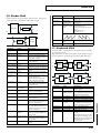
Disk-Related Functions (Disk Mode)
This chapter covers disk-related operations such as saving data to
disk and loading data from disk. Read it as necessary.
Transferring Data (USB Mode)
This explains how to connect the V-Synth to your computer, and
transfer data such as patches and waves. Read this as necessary.
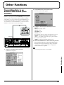
Other Functions
This explains how to transmit data to an external MIDI device (Data
Transfer), and how to restore all data of the V-Synth to the factory
settings (Factory Reset). Read it as necessary.
Appendices
This chapter contains a troubleshooting section for use when the VSynth is not functioning as expected. There is also a list of messages
that you can refer to if an message appears on the display. A list of
parameters and a MIDI implementation chart are also provided.
6
These are notes. Be sure to read them.
These are reference memos. Read it as necessary.
These are hints for operating the V-Synth. Read it as necessary.
These provide information from related reference pages. Read it
as necessary.
The display screens printed in this owner’s manual are based on
the factory settings. However, please be aware that in some cases
they may differ from the actual factory settings.
Contents
USING THE UNIT SAFELY......................................................................3
IMPORTANT NOTES ...............................................................................4
How To Use This Manual........................................................................6
Notation Used in This Owner’s Manual...................................................................................... 6
Main Features........................................................................................10
Panel Descriptions................................................................................12
Front Panel................................................................................................................................................. 12
Rear Panel .................................................................................................................................................. 15
Overview of the V-Synth.......................................................................16
How the V-Synth Is Organized .............................................................................................................. 16
Basic Structure ............................................................................................................................... 16
Polyphony ...................................................................................................................................... 16
About Multitimbral Performance ............................................................................................... 16
Memory...................................................................................................................................................... 17
Memory Structure ......................................................................................................................... 17
Basic Operation of the V-Synth .............................................................................................................. 18
Changing Operating Modes ([MODE]) ..................................................................................... 18
Basic Touch Screen Operation..................................................................................................... 19
Moving the Cursor........................................................................................................................ 20
Editing a Value .............................................................................................................................. 20
Playing in Patch Mode..........................................................................21
About the PATCH PLAY Screen............................................................................................................ 21
Displaying PATCH PLAY Screen............................................................................................... 21
Selecting a Patch ....................................................................................................................................... 21
Selecting Favorite Patches (Patch Palette) ................................................................................. 22
Selecting Patches from the List.................................................................................................... 22
Transposing the Keyboard in Semitone Steps (Transpose)................................................................ 22
Transposing the Keyboard in Octave Units (Octave Shift) ................................................................ 23
Playing Single Notes (Mono) .................................................................................................................. 23
Creating Smooth Pitch Changes (Portamento) .................................................................................... 23
Playing Arpeggios (Arpeggiator)........................................................................................................... 24
Holding an Arpeggio.................................................................................................................... 24
Using an External MIDI Keyboard to Play Arpeggios ............................................................ 24
Making Arpeggiator Settings ...................................................................................................... 25
Creating an Original Arpeggio Pattern (Pattern Edit)............................................................. 25
Applying Various Effects to the Sound................................................................................................. 28
Applying an Effect by Touching Your Finger to the Pad (Time Trip Pad)........................... 28
Applying an Effect by Passing Your Hand Over the D Beam (D Beam Controller) ........... 29
Applying an Effect by Turning a Knob (Assignable Controller) ........................................... 30
Synchronizing Music and Video While You Play the V-Synth (V-LINK) ....................................... 30
Enter V-LINK Mode ..................................................................................................................... 31
V-LINK Functions that the V-Synth Can Control and MIDI Messages ................................ 31
Creating a Patch....................................................................................32
How to Make the Patch Settings ............................................................................................................ 32
Initializing Patch Settings (PATCH Init) ................................................................................... 33
Copying Patch Settings (PATCH Copy) .................................................................................... 33
Naming a Patch (PATCH Name) ........................................................................................................... 34
Saving Patches (PATCH Write).............................................................................................................. 34
Auditioning the Save-Destination Patch (Compare) ............................................................... 35
Registering a Favorite Patch (Patch Palette) ............................................................................. 35
7
Contents
Deleting Patches (PATCH Delete) ......................................................................................................... 36
Functions of Patch Parameters ............................................................................................................... 36
Settings Common to the Entire Patch (Common) .................................................................... 36
Modifying Waveforms (OSC1/OSC2) ....................................................................................... 42
Mixing/Modulating Two Sounds (Mod) .................................................................................. 46
Applying Various Effects to Each Note You Play (COSM1/COSM2) .................................. 46
Adjusting the Volume and Pan (TVA)....................................................................................... 47
Making Envelope Settings ........................................................................................................... 48
Making LFO Settings .................................................................................................................... 49
Setting Effects for a Patch (Effect)............................................................................................... 50
Zone Settings (Zone) ................................................................................................................................ 52
Splitting the Keyboard to Play Different Sounds (Split) ......................................................... 52
Creating a Drum Patch (Drum)................................................................................................... 53
Creating and Editing Samples (Sample Mode) ..................................55
Sampling .................................................................................................................................................... 55
Settings Before You Sample (What Is a Template?) ................................................................. 55
Sampling Procedure ..................................................................................................................... 56
Resampling..................................................................................................................................... 60
Setup Settings ................................................................................................................................ 60
Pre-Effect Settings ......................................................................................................................... 61
Metronome Settings...................................................................................................................... 62
Checking Sample Information................................................................................................................ 63
Importing a Sample.................................................................................................................................. 64
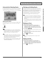
Editing a Sample....................................................................................................................................... 64
Common Procedure for Editing.................................................................................................. 64
Editing the Specified Region of the Sample .............................................................................. 66
Loop Region Settings.................................................................................................................... 68
Original Tempo Setting ................................................................................................................ 69
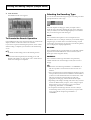
Converting the Sample to V-Synth Data (Encode) .............................................................................. 69
Selecting the Encoding Type ....................................................................................................... 70
Automatically Detecting Events ................................................................................................. 71
Deleting and Adding Events ....................................................................................................... 71
Saving a Sample........................................................................................................................................ 72
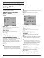
Settings Common to All Modes (System Mode) ................................73
How to Make the System Function Settings......................................................................................... 73
Saving the System Settings (Write)............................................................................................. 73
Initializing the System Settings (Init) ......................................................................................... 73
Functions of System Parameters ............................................................................................................ 74
Settings Common to the Entire System (Common) ................................................................. 74
Controller Settings (Controller) .................................................................................................. 77
V-LINK Settings (V-LINK) .......................................................................................................... 80
Disk-Related Functions (Disk Mode)...................................................83
About Disk Utility .................................................................................................................................... 83
Basic Disk Utility Operations.................................................................................................................. 83
Sorting the Files Displayed in the File List................................................................................ 84
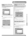
Loading a Project from Disk into the V-Synth (Load Project) ........................................................... 84
Saving Project on Disk (Save Project) .................................................................................................... 85
Delete Unneeded Files (Clean Project) .................................................................................................. 85
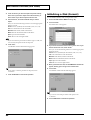
Importing Individual Patch or Wave Files (Import Files) .................................................................. 85
Initializing a Disk (Format) ..................................................................................................................... 86
Functions Related to Files and Folders (Tools) .................................................................................... 87
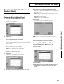
Copying Files/Folders (Copy) .................................................................................................... 87
Moving Files/Folders (Move) ..................................................................................................... 87
Deleting Files/Folders (Delete)................................................................................................... 88
8
Contents
Renaming a Files/Folders (Rename) ..................................................................................................... 89
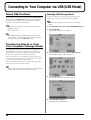
Connecting to Your Computer via USB (USB Mode).........................90
About USB Functions............................................................................................................................... 90
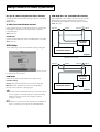
Transferring Files to or from Your Computer (Storage Mode) ......................................................... 90
Windows Me/2000/XP Users..................................................................................................... 91
Macintosh Users ............................................................................................................................ 93
Examples of Using Storage Mode............................................................................................... 94
Exchanging MIDI Messages with Your Computer (MIDI Mode)..................................................... 96
Driver Installation and Settings .................................................................................................. 96
Other Functions ....................................................................................97
Transmitting Data to an External MIDI Device (Data Transfer) ....................................................... 97
Reset to Default Factory Settings (Factory Reset) ................................................................................ 98
Viewing Various Information (Info)...................................................................................................... 98
Adjusting the Sensitivity of the Touch Screen/Time Trip Pad/D Beam Controller
(Calibration Mode) ................................................................................................................................... 99
Adjusting the Sensitivity of the Touch Screen .......................................................................... 99
Adjusting the Sensitivity of the Time Trip Pad ...................................................................... 100
Adjusting the Sensitivity of the D Beam Controller............................................................... 100
Appendices ................................ 101
Parameter List .....................................................................................102
Patch Parameters .................................................................................................................................... 102
System Parameters ................................................................................................................................. 108
COSM List............................................................................................111
COSM Parameters .................................................................................................................................. 111
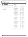
Effects List...........................................................................................116
MFX Parameters ..................................................................................................................................... 116
Chorus Parameters ................................................................................................................................. 138
Reverb Parameters ................................................................................................................................. 138
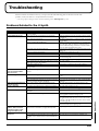
Troubleshooting..................................................................................145
Problems Related to the V-Synth ......................................................................................................... 145
Problems Related to the USB Driver (Windows)............................................................................... 146
Problems Related to the USB Driver (Macintosh) ............................................................................. 148
Message List .......................................................................................149
ERROR Screens ....................................................................................................................................... 149
WARNING Screens................................................................................................................................ 150
Message Boxes ........................................................................................................................................ 151
About MIDI ...........................................................................................152
MIDI Implementation...........................................................................153
Specifications......................................................................................172
Index.....................................................................................................173
Installing the PC Card Protector........................................................179
9
Main Features
With this synthesizer, every component involved in sound
creation has been taken to the next stage of evolution
The V-Synth brings together the ideal combination of sound generators, together with an interface that dynamically links your sensitivities with
the sound. It’s a powerful synthesizer that only Roland could have produced. The sounds of the V-Synth have a living character that goes beyond
the limits of previous synthesizers.
■ The ideal combination of sound
generators
■ An interface that gives life to the
sound
● Flexible sound generator structure
● Intuitive user interface
The sound generator section consists of OSC, MOD, COSM, and
TVA blocks, and allows you to flexibly change the way in which
these blocks are connected. Sections other than the TVA provide
multiple types, and can be combined freely.
The V-Synth provides a rich variety of controllers for hands-on
operation, which puts you in direct and intuitive control of the
sound: a touch-operated display, the Time Trip pad, twin D Beam
controllers that detect not only up/down but also left/right
movement, and highly sensitive knobs.
Since each section can be switched on/off in real time from the
panel, it’s always easy to understand how the sound is structured.
Most of the sound generator parameters can be assigned to these
controllers for direct control.
● Versatile oscillators using
VariPhrase technology
● Powerful time-control functions
Since the oscillators have independent envelopes and LFOs, they
themselves have the functionality of synthesizers. You can choose
from three types: analog, PCM, and external input.
The VariPhrase sound generator of the V-Synth provides a Time Trip
function that can bring the waveform playback to a stop in real time,
and trace backward or forward from that point.
For example, since the PCM oscillators provide VariPhrase
functionality, you can change the waveform playback speed in the
forward or reverse directions.
In addition, VariPhrase waveforms, LFO, envelope, arpeggiator, and
effects can all be made to operate in synchronization at the same
tempo. For example, a waveform with movement such as a rhythm
loop can easily be synthesized in units of individual notes. Of course
you can also synchronize to MIDI Clock messages from an external
device.
Approximately 300 different preset waveforms are built-in. In
addition, you can use waveforms that you sampled from the analog
or digital input.
The powerful analog modeling sound generator creates a waveform
by internal calculation, and is great for creating unique tonal
changes, such as adding fatness or more of an edge to your sound.
● COSM processing for creating
unique sounds
The COSM section uses a rich variety of processing in addition to the
usual TVF to vary the sound in extreme ways. For example, you can
use a sideband filter to give a metallic resonance to simple white
noise. You can use a resonator to add the body resonances of a
musical instrument. Processes such as wave shaper and guitar amp
modeling are also provided.
Since these effects are independent for each voice, you can play
chords while preserving the sense of pitch.
● Carefully selected effects
Three types of carefully selected effects are built-in: MFX (multieffects), chorus, and reverb.
Also included is a newly developed Pseudo Stereo effect that adds a
sense of stereo to monaural sample data, allowing you to create a
variety of sound fields.
10
The arpeggiator lets you program a pattern for each sound, and also
supports control changes.
● New specially optimized preset
sounds
The new built-in sounds created specifically for the V-Synth give
you a wide range of expression simply when played from the
keyboard, and are also optimized for performance from the Time
Trip pad and D Beam controllers.
From the day you start playing the V-Synth, you can start taking
advantage of the performance potential offered by its Time Trip pad
and D Beam controllers.
Main Features
■ Use with other devices for even
greater possibilities
● Open system architecture
The V-Synth lets you customize all patches and wave data. By
connecting your computer via USB, you can easily back up all of
your data.
In addition to being able to sample using the V-Synth itself, you can
also import WAV or AIFF format files, so audio data created on
other devices can easily be loaded into the V-Synth and used.
Furthermore, you can store data on PC cards for easy exchange of
sound data.
● A full complement of external
interfaces
What is VariPhrase?
VariPhrase has the following advantages:
1 Capable of changing the pitch, rate of time expansion/
compression and voice characteristics (formant) on a realtime basis.
2 Allows easy synchronization to tempo and pitch.
3 A single sample covers an extended range of keys compared
to conventional digital samplers.
4 Retains sound quality, while implementing the above three
advantages.
VariPhrase overcomes many problems that conventional
samplers and digital recorders have with audio phrases.
Typical issues with Digital Samplers and Digital recorders
• Changing tempo affects Pitch.
The digital audio interface supports both optical and coaxial
connections, and sampling rates of 44.1 kHz, 48 kHz, and 96 kHz,
making the V-Synth ideal for any digital music production
environment.
• Changing the pitch of phrases affects tempo and formant of
the sound.
The USB connector supports file transfer or MIDI communication,
and you can select its function depending on your needs.
• Most samplers require multiple samples over limited key
ranges for realistic playback of a sound.
The PC card slot makes it easy to store large amounts of data on
commercially available media such as Compact Flash or SmartMedia
via a PC card adaptor.
• Samples of the same tempo must be available for
performing chords, otherwise the notes of the chord will be
out of sync.
● V-LINK function
• Pitch or tempo changes on Digital samplers tends to
degrade audio quality.
• Limited control of audio phrases. You cannot adjust a
partial section of a sound in real-time.
VariPhrase solves all of these problems.
is a function that links music and video
performance. By using a video device that supports V-LINK, you can
easily link various video effects with your performances.
If the V-Synth is connected to an Edirol DV-7PR, you can use the VSynth’s controllers to adjust the brightness or color of the image,
vary the playback speed, or switch between images.
11
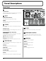
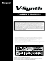
Panel Descriptions
Front Panel
1
1 2
Volume Slider
Adjusts the overall volume that is output from the rear panel MAIN
OUT jacks and PHONES jack.→ (Quick Start; p. 4)
3
5
8
4
2 INPUT
9
[PEAK] (Peak Indicator)
6
This will light when the input volume is too high.
7
[LEVEL]
Adjusts the volume of the signal input through the INPUT jacks on
the rear panel. → (p. 57)
17
3 D BEAM
You can apply a variety of effects to sounds simply by moving your
hand. → (p. 29)
Indicators (L, R)
If the D Beam controller is on, these will light when you move your
hand over the controller.
[ON/OFF] (TIME TRIP, TIME, PITCH,
ASSIGNABLE)
Switches the D Beam controller on/off. The effect to be controlled
can be selected by pressing the relevant button.
TIME TRIP: Apply the Time Trip effect.
5 V-LINK
Enables or disables control of an externally connected V-LINK
device.
6 ASSIGNABLE CONTROL
You can assign a variety of parameters and functions to the two
knobs ([C1], [C2]), and use them to modify the sound in realtime.
→ (p. 30)
TIME: Apply the Time Control effect.
PITCH: Apply the Pitch Control effect.
ASSIGNABLE: Apply the effect that is specified for each sound.
7 ARPEGGIO
Here you can control the arpeggiator.
4 TIME TRIP PAD
By touching the pad surface with your finger you can apply a variety
of effects to the sound.
Indicator
This will light when you touch the Time Trip Pad.
[TIME TRIP]
Switches to the Time Trip effect.
[ASSIGNABLE]
Switches to the effect that is specified for each patch.
[HOLD]
Switches hold on/off for the effect controlled by the Time Trip pad.
12
[TEMPO]
Adjusts the tempo of the arpeggios.
[ON/OFF]
Switches the Arpeggiator on/off.
[HOLD]
Switches the Arpeggiator hold on/off.
10
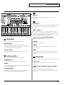
Panel Descriptions
10
12
13
Display
This displays information regarding the operation you are
performing.
11
11
VALUE Dial
14
15
16
This is used to modify values. If you hold down [SHIFT] as you turn
the VALUE dial, the value will change in greater increments.
→ (p. 20)
[DEC/-], [INC/+]
This is used to modify values. If you keep on holding down one
button while pressing the other, the value change accelerates. If you
press one of these buttons while holding down [SHIFT], the value
will change in bigger increments. → (p. 20)
[
8 KEYBOARD
Here you can change the pitch range of the keyboard.
[TRANSPOSE]
], [
], [
], [
] (Cursor Buttons)
Moves the cursor location up/down/left/right. → (p. 20)
[MODE]
Opens the Mode Menu window.
Specifies transposing the keyboard in semitone steps. → (p. 22)
[SHIFT]
Pressing this button while holding down [-OCT] or [+OCT] allows
you to set the desired amount of transposition.
This button is used in conjunction with other buttons to execute
various functions.
[-OCT], [+OCT]
[EXIT]
These buttons adjust the pitch of the keyboard in octave steps.
→ (p. 23)
Return to the PLAY screen, or close the currently open window. In
some screens, this causes the currently executing function to be
aborted.
9 PATCH PALETTE
Here you can register and recall your favorite patches.
[NUMBER] (1–8)
12 STRUCTURE
Here you can turn each sound-producing element (section) on or off.
These buttons let you select/register your favorite patches.
[1], [2], [3]
[BANK]
Switches the structure type (the way in which the sections are
connected).
You can change the Patch Palette bank by holding down this button
and pressing [NUMBER] (1–8)
[OSC1], [OSC2], [MOD], [COSM1], [COSM2],
[TVA]
[PATCH ASSIGN]
These buttons switch the corresponding section on/off.
You can register the currently selected patch as a favorite patch by
holding down this button and pressing [NUMBER] (1–8).
Only the buttons of the structure type selected by [1], [2], or [3] are
active.
13
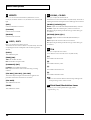
Panel Descriptions
13 EFFECTS
15 COSM1, COSM2
Here you can switch the onboard effects (multi-effects, chorus,
reverb) on/off. When an effect is on, the indicator for its button will
light.
Here you can adjust the COSM sections.
[MFX]
[WIDTH]/[CUTOFF]/[P1]
Switches multi-effects on and off.
WIDTH: Adjusts the width when SBF (Side Band Filter) is selected.
[CHORUS]
These knobs are active when COSM is on (indicator lit). The result of
adjusting these knobs will depend on the COSM type that is selected.
CUTOFF: Adjusts the cutoff frequency when TVF is selected.
Switches chorus on and off.
P1: Adjusts the parameter specified for the type when other types
are selected.
[REVERB]
[DETUNE]/[RESO]/[P2]
Switches reverb on and off.
DETUNE: Adjusts the detune when SBF (Side Band Filter) is
selected.
14 OSC1, OSC2
RESO: Adjusts the resonance when TVF is selected.
Here you can adjust the oscillator section.
P2: Adjusts the parameter specified for the type when other types
are selected.
These knobs are active if the oscillator is on (indicator lit). The result
of adjusting these knob will depend on the oscillator type that is
selected.
16 TVA
[PITCH]
Here you can adjust the TVA section.
These sliders are active when the TVA is on (indicator lit).
This modifies the pitch.
[TIME]/[PW]
[A]
This modifies the Attack Time.
TIME: This modifies the time.
PW: This modifies the pulse width.
[D]
[FORMANT]/[FAT]
This modifies the Decay Time.
FORMANT: This modifies the formant.
[S]
FAT: Adjusts the fatness of the sound when using an analog
oscillator.
This modifies the Sustain Level.
[LFO DP1], [LFO DP2], [LFO DP3]
These knobs adjust the depth of the LFO that is applied to the
parameters of the knobs located above each knob.
[LFO RATE]
[R]
This modifies the Release Time.
You can also use these sliders to make envelope settings in the
envelope setting screens of other sections.
This modifies the LFO rate.
[LEVEL]
This modifies the volume.
14
17 Pitch Bend/Modulation Lever
This allows you to control pitch bend or apply vibrato.
→ (Quick Start; p. 17)
Panel Descriptions
Rear Panel
fig.00-02
fig.00-03
fig.00-07
MIDI Connectors (IN, OUT, THRU)
POWER Switch
Press to turn the power on/off. → (Quick Start; p. 4)
These connectors can be connected to other MIDI devices to receive
and transmit MIDI messages.
AC Inlet
fig.00-08
Connect the included power cord to this inlet. → (Quick Start; p. 3)
fig.00-04
CTRL 1, CTLR 2 PEDAL Jack
PC CARD Slot
A PC card can be inserted here.
For details on installing the included PC card protector, refer to
p. 178.
fig.00-05
You can connect optional expression pedals (EV-5, etc.) to these
jacks. By assigning a desired function to a pedal, you can use it to
select or modify sound or perform various other control.
→ (p. 79, Quick Start; p. 18)
HOLD PEDAL Jack
An optional pedal switch (DP series) can be connected to this jack for
use as a hold pedal. → (Quick Start; p. 18)
fig.00-09
INPUT Jacks (L, R)
USB Connector
An external audio source such as a CD player can be connected to
these jacks for sampling or external input.
This is a USB connector. You can connect it to your personal
computer to send or receive files and MIDI messages.
GAIN Switch
DIGITAL AUDIO INTERFACE Connector (OPTICAL
IN/OUT, COAXIAL IN/OUT)
Set this to the “MIC” position if connecting a mic, or to the “LINE”
position if connecting any other type of device.
This selects the input gain of the INPUT jacks.
(conforming to S/P DIF).
These connectors input/output a digital audio signal (stereo). The
output signal is identical to the signal that is output from the MAIN
OUT jacks.
fig.00-10
DIRECT OUT Jacks (L, R)
S/P DIF is a digital interface format used for consumer digital
audio devices.
This jack is a stereo output of the sound unprocessed by onboard
effects. An external effects processor or other devices can be
connected to these jacks.
fig.00-06
MAIN OUT Jacks (L (MONO), R)
LCD CONTRAST Knob
Adjusts the display contrast. → (Quick Start; p. 5)
These jacks output the audio signal to the connected mixer/amplifier
system in stereo. For mono output, use the L jack.
→ (Quick Start; p. 3)
PHONES Jack
This is the jack for connecting headphones (sold separately).
→ (Quick Start; p. 3)
15
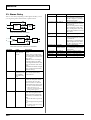
Overview of the V-Synth
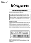
How the V-Synth Is Organized
Section name
OSC1, OSC2
Basic Structure
Broadly speaking, the V-Synth consists of a controller section and a
sound generator section.
fig.01-01.e
MOD
COSM1, COSM2
Sound
Generator
Section
TVA
Play
Effects
MFX
Controller Section (controllers such as
keyboard, pitch bend lever, etc.)
The right side of the V-Synth’s front panel is where the controls for
the Sound Generator section are located. The controls on the left side
are mainly those of the Controller section.
REVERB
Sound Generator Section
The sounds you play on the V-Synth are called patches. Each patch
consists of a structure (an arrangement of its six sections), zones
(which allow for sixteen individual setups for sixteen key ranges),
and three effects.
fig.01-02.e
Zone 16
Zone 15
Zone 2
Zone 1
CHORUS
Patch
Function
This section generates the sound on which
a patch is based. The sound is produced either by built-in preset waves or sampled
waves, or by calculating an analog modeling waveform. An external audio input
source can also be used.
This section mixes and modulates the two
audio signals.
This section applies a wide variety of processing including filtering. This differs
from the effects in that effects are applied to
the final mix of the sound, COSM is applied
to each individual note.
This section creates time-variant changes in
volume, and sets the pan position.
function
The multi-effects are multi-purpose effects
that can completely change the nature of
the patch’s sound. There are 41 different effects types; select and use the type that suits
your aims.
Applies a chorus effect to give the sound
depth and spaciousness.
Applies a reverb effect to add ambience to
the sound.
Controller Section
The controller section consists of the keyboard, pitch bend/
modulation lever, time trip pad, D Beam controller, C1/C2 knobs,
arpeggiator, and pedals connected to the rear panel. When you
manipulate these controllers, they send performance data to the
sound generator section, causing the V-Synth to create sound.
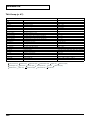
Polyphony
The maximum polyphony of the V-Synth depends on the OSC and
COSM types used by the patch.
Changing the effect type or switching effects on/off does not
affect the available polyphony.
About Multitimbral Performance
The V-Synth allows up to 16-part multitimbral operation, and can be
played multitimbrally by performance data sent from an external
device. You can use the V-Synth to play the sounds of a song you
created on your sequencer, or as part of an ensemble. From the
keyboard you can play only the patch that is assigned to part 1. The
PATCH Information window shows you the patch that is assigned
to each part (p. 98).
A sound module that allows you to control multiple sounds
independently in this way is called a multitimbral sound module.
16
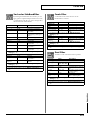
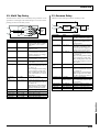
Memory
Work Area/Temporary Area
Memory Structure
When you turn on the power of the V-Synth, or when you load a
project in Disk mode, the project data is placed in temporary
memory called the work area.
fig.01-03.e
Sampling and sample editing operations modify the data that is in
the work area.
V-Synth
The currently playable patch data is then further placed (from the
work area) into a location called the temporary area. This means
that even after editing a patch, you can return to the unedited
condition by once again recalling that patch.
Internal Memory
Project
Patch
512
Since sample data and patch data that you edit will disappear if you
simply turn off the power, you must save (SAVE/WRITE) it if you
want to keep your changes.
Wave
999
PC Cards
System
Internal memory can hold only one project, but you can use
commercially available PC cards to store additional projects.
Sampling Memory
Preset Memory
Select
Work Area
The amount of memory you can use for sampling will depend on the
state of the project that is currently loaded into the work area. With
the factory-set project, there is approximately 115 seconds (stereo) /
230 seconds (monaural) of sampling memory. If you delete the
factory-set waves, you will be able to use a maximum of
approximately 280 seconds (stereo) / 560 seconds (monaural) of
sampling memory. However since a maximum of approximately 56
seconds (stereo) / 113 seconds (monaural) can be saved in internal
memory, you will need to use a commercially available PC card if
you want to store more samples than this.
Save
Temporary Area
USB
PC Card
Project
Patch
512
Load
Wave
999
Save
System
Computer
Project
The largest unit of memory used by the V-Synth is the project. A
project contains up to 512 patches, up to 999 waves, and various
system settings.
* The above values are for when the sample is encoded using the “LITE”
type.
The factory-set waves can be restored using the Factory Reset
operation (p. 98) even if they have been erased.
Preset Memory
Preset memory contains the state of the internal memory when the
unit is shipped from the factory. If, after erasing the internal
memory, you once again want to use the factory-set patches or
waves, you can either perform the Factory Reset operation or use
Disk mode to import the factory data from preset memory.
The V-Synth uses one project at a time.
Internal Memory
The V-Synth has internal memory that stores a project. When the VSynth is shipped from the factory, this memory already contains
patch and wave data, but you are free to overwrite any of this. You
can always restore the memory to the factory-set contents (Factory
Reset).
USB
If you connect the V-Synth to your computer via a USB cable,
projects, patches, and wave data in the V-Synth’s internal memory or
on a PC card can be saved (backed up) to the hard disk or other
media on your computer.
In addition, wave data created on the V-Synth can also be used by
software running on your computer, or wave data created by your
computer software can be used on the V-Synth.
17
Overview of the V-Synth
Overview of the V-Synth
Overview of the V-Synth
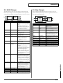
Basic Operation of the V-Synth
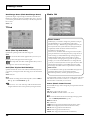
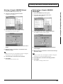
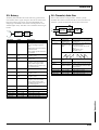
Sample Mode
fig.SAMPLE_50
Changing Operating Modes
([MODE])
The V-Synth has eight operating modes: Patch mode, Sample mode,
System mode, Disk mode, USB mode, Calibration mode, Factory
reset mode and Demo play mode. To access the desired V-Synth
feature, you must select the appropriate mode.
Here’s how to change modes.
1. Press [MODE].
The V-SYNTH MODE MENU window appears.
fig.MODE_50
In this mode, you can sample the waves that form the basis of the
sounds you create, and edit the sampled waves.
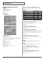
System Mode
fig.SYSTEM_50
2. Touch the touch screen to select the desired mode.
When you select a mode, the screen for that mode appears. The
currently selected mode is shown in the upper left of each
screen.
fig.01-04
In this mode, you can set the overall behavior of the V-Synth, such as
its tuning and how it handles received MIDI messages.
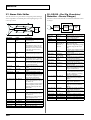
Disk Mode
fig.DISK_50
Patch Mode
fig.PATCH_50
In this mode you can play a single patch from the keyboard, and edit
patch settings.
18
In this mode, you can perform operations related to disks, such as
saving data on a disk or loading data from a disk.
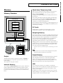
Basic Touch Screen Operation
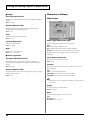
USB Mode
fig.USB_50
The V-Synth features a touch screen. The touch screen lets you
perform a variety of operations by lightly touching the screen.
The touch screen responds to a light touch. Pressing the touch
screen with too much force, or with a hard object, may damage
it. Be careful not to apply excessive force, and touch it only with
your finger.
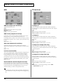
Enabling/Disabling the Beep Tone
In this mode, you can connect the V-Synth to your computer and
exchange patch or wave data.
You can specify whether or not a beep tone will be heard when you
touch a valid point on the touch screen.
Calibration Mode
At the factory setting, the beep tone will be sounded.
fig.CALIBRATION_50
1. In the upper right of the screen, touch <▼>.
A pulldown menu appears.
fig.01-05_50
In this mode you can adjust the response of the touch screen and D
Beam controller.
Factory Reset Mode
fig.FACTORY_50
2. In the pulldown menu, touch <Beep> to add a check mark
(✔).
With this setting, the beep tone will be heard. If you perform the
same procedure once again, the check mark will be cleared and
the beep tone will no longer be heard.
If you have turned off the beep tone, a “∇” appears in the title
area at the top of the screen when you touch a valid point on the
touch screen.
fig.01-06
In this mode, you can reset to default factory settings.
Demo Play Mode
fig.DEMO_50
In this mode, you can play the built-in demo songs.
Demo Song: New Toys
Amin Bhatia © 2002 Roland Corporation
19
Overview of the V-Synth
Overview of the V-Synth
Overview of the V-Synth
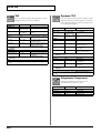
Moving the Cursor
Editing a Value
A single screen or window displays multiple parameters or items for
selection. To edit a parameter’s value, move the cursor to the value.
To select an item, move the cursor to the item. The cursor is a black
rectangle, and the parameter value or item you select with the cursor
is highlighted (displayed in inverted colors).
To edit a value, you can use the VALUE dial, [INC/+] [DEC/-], or
drag on the touch screen.
fig.01-07.e
In each V-Synth screen, you can select a value using the cursor as
described earlier, and modify its value.
Cursor
Each parameter has its own range of possible values. You cannot
set any value smaller than the minimum value or greater than
the maximum value.
VALUE Dial
Turning the VALUE dial clockwise increases the value, and turning
it counterclockwise decreases its value. Hold down [SHIFT] as you
move the VALUE dial to increase value increments to make large
value changes more quickly.
fig.01-10
Cursor Buttons
Press [
cursor.
], [
], [
], or [
] (the cursor buttons) to move the
fig.01-08
[INC/+] and [DEC/-]
[
]: moves the cursor up.
[
]: moves the cursor down.
[
]: moves the cursor to the left.
[
]: moves the cursor to the right.
Press [INC/+] to increase the selected value, and [DEC/-] to
decrease it. Keep the button pressed for continuous adjustment. For
faster value increases, keep [INC/+] pressed down and press [DEC/
-]. To decrease values quickly, keep [DEC/-] pressed down and
press [INC/+].
fig.01-11
Touch Screen
Directly touch a parameter value to move the cursor.
fig.01-09
Touch Screen
Touch a parameter value, and drag your finger up/down or left/
right. Dragging upward or to the right increases the value, and
dragging downward or to the left decreases the value.
fig.01-12
20
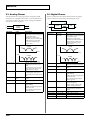
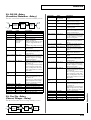
Playing in Patch Mode
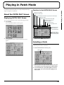
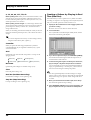
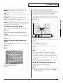
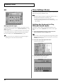
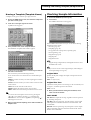
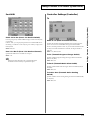
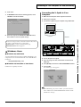
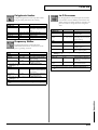
Functions in the PATCH PLAY Screen
Playing in Patch Mode
Patch mode is the mode in which you can play the keyboard using a
single sound (patch or rhythm set).
fig.02-01.e
Indicates a list of patches.
About the PATCH PLAY Screen
Indicates the current mode.
Indicates the MIDI transmit channel (Tx) and receive channel (Rx).
Indicates/sets the tempo.
Displaying PATCH PLAY Screen
Sets the Transpose and the Octave Shift.
To access the PATCH PLAY screen, use the following procedure.
Indicates the name and zone
of the selected patch.
1. Press [MODE].
Indicates/sets the zone
The V-SYNTH Mode MENU window appears.
Opens the pulldown menu.
fig.MODE_50
Indicates/selects the
number and name
of the selected patch.
Graphically displays
the parameter settings
of the selected patch.
2. Touch <PATCH>.
Displays the various patch setting screens.
You will enter Patch mode, and the PATCH PLAY screen
appears.
fig.PATCH_50
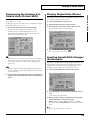
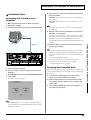
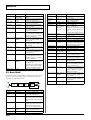
Selecting a Patch
V-Synth contains 512 patches for you to select and use.
All of these patches can be overwritten.
1. Access the PATCH PLAY screen (p. 21).
fig.02-02.e
Patch number
2. Move the cursor to the patch number, either by using the
cursor buttons or by touching the patch number display.
3. Turn the VALUE dial, or press [INC/+][DEC/-] to select a
patch number. You can also do this by dragging on the
touch screen.
21
Playing in Patch Mode
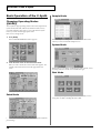
Selecting Favorite Patches (Patch
Palette)
You can bring together your favorite and most frequently used
patches in one place by registering them into the patch palette. By
using this function, you can rapidly select favorite patches from
internal memory or a Wave Expansion Board.
For details on how to register a patch in the patch palette, refer
to “Registering a Favorite Patch (Patch Palette)” (p. 35).
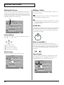
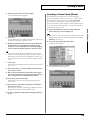
4. To view other patches, touch <017-032>–<241-256>, located
at either side of the screen. To view higher-numbered
patches, touch <257-512>, located at the bottom of the
screen.
5. Touch <OK>.
The patch is selected and the PATCH List window closes.
1. Access the PATCH PLAY screen (p. 21).
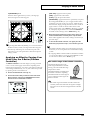
Transposing the Keyboard in
Semitone Steps (Transpose)
2. Press NUMBER [1]–[8] to select a patch.
Transpose changes keyboard pitch in units of semitones.
fig.02-03
This function is useful when you play transposed instruments such
as trumpet or clarinet following a printed score.
1. Press [TRANSPOSE] to light indicator.
This turns Transpose on.
3. To switch the patch palette bank, hold down [BANK] and
press NUMBER [1]–[8].
When you press [BANK], the indicator of the currently selected
bank button (NUMBER [1]–[8]) will blink.
2. While holding down [TRANSPOSE], press [+OCT] or [-OCT]
to transpose the keyboard.
Pressing [+OCT] once while holding down [TRANSPOSE] will
raise the keyboard one semitone.
Pressing [-OCT] once while holding down [TRANSPOSE] will
lower the keyboard one semitone.
If you continue pressing [PATCH ASSIGN] or [BANK], the
PATCH PALETTE window will appear. In this window you can
view the patches that are registered in the currently selected
bank.
The specified Transpose setting will be shown in the “Trans”
indication of PATCH PLAY screen.
fig.02-06
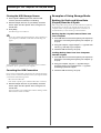
Selecting Patches from the List
You can display a list of patches and select a patch from that list.
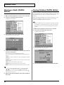
1. Access the PATCH PLAY screen (p. 21).
2. Touch <List> in the upper left area of the display.
The PATCH List window appears.
fig.02-04_50
Alternatively, you can move the cursor to “Trans” in the PATCH
PLAY screen and turn the VALUE dial or use [INC/+] [DEC/-]
to make the setting. You can also do this by dragging on the
touch screen.
3. To turn off Transpose, press [TRANSPOSE] once again so
that its indicator goes off.
The Transpose setting you make will be maintained.
3. Select a patch from the list.
Either turn the VALUE dial or use [INC/+][DEC/-] to select a
patch. You can also select a patch by touching it on the display.
If you select a patch in the list and play the keyboard, the
selected patch will sound. This is a useful way to audition the
sound of a patch.
22
There is a single Transpose setting (Setup parameter) for the
entire V-Synth. The changed setting will be remembered even if
you switch patches.
Transposing the Keyboard in
Octave Units (Octave Shift)
The Octave Shift function transposes the pitch of the keyboard in 1
octave units (-3– +3 octaves).
For playing a bass part more easily using your right hand, transpose
the keyboard down by 1 or 2 octaves.
1. Press [+OCT] or [-OCT] and its indicator will light.
Pressing [+OCT] once will raise the keyboard 1 octave.
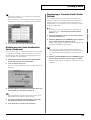
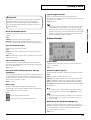
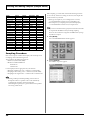
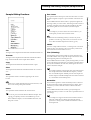
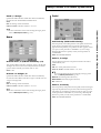
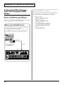
Playing Single Notes (Mono)
When using a patch for a naturally monophonic instrument such as
sax or flute, it is effective to play in mono.
1. Access the PATCH PLAY screen (p. 21).
2. At the bottom of the screen, touch <Common>.
3. In the left side of the screen, touch the <General> tab.
The Patch Edit Com General screen appears.
fig.02-07_50
Pressing [-OCT] once will lower the keyboard 1 octave.
The specified Octave Shift setting will be shown in the “Oct”
indication of PATCH PLAY screen.
fig.02-05
4. In the “Mono/Poly” field, touch <
>.
Now you can play in mono mode.
Alternatively, you can move the cursor to “Oct” in the PATCH
PLAY screen and turn the VALUE dial or use [INC/+] [DEC/-]
to make the setting. You can also do this by dragging on the
touch screen.
There is a single Octave Shift setting (Setup parameter) for the
entire V-Synth. The changed setting will be remembered even if
you switch patches.
Creating Smooth Pitch Changes
(Portamento)
Portamento is an effect which smoothly changes the pitch from the
first-played key to the next-played key. By applying portamento
when Mono mode is selected (see the preceding item), you can
simulate performance effects such as slurring on a violin.
1. Access the PATCH Edit Com General screen (p. 21).
fig.02-07_50
2. To turn off the Octave Shift function, press the other button
[+OCT] or [-OCT] of that pressed in step 1. The indicator will
go off.
2. In the “Portamento” field, touch the on/off switch to turn it
“ON.”
You’re ready to play portamento.
3. When you want to change the portamento setting, edit the
following parameters in the screen of step 2.
Mode (Portamento Mode), Type (Portamento Type), Time
(Portamento Time), Time Velo Sens (Portamento Time Velocity
Sens)
See (p. 37) for each parameter’s functions.
23
Playing in Patch Mode
Playing in Patch Mode
Playing in Patch Mode
Playing Arpeggios
(Arpeggiator)
The V-Synth comes with an arpeggiator that can play arpeggios
automatically. Once you turn on the arpeggiator, the keys you press
will automatically be played as an arpeggio.
1. Access the PATCH PLAY screen (p. 21).
2. Press ARPEGGIO [ON/OFF] to make the indicator light.
The arpeggiator is turned on.
3. Play the keyboard.
Using an External MIDI Keyboard
to Play Arpeggios
You can also use the keyboard of an external MIDI instrument to
play arpeggios.
1. Use a MIDI cable to connect the V-Synth’s MIDI IN connector
to the MIDI OUT connector of your external MIDI keyboard.
2. Access the PATCH PLAY screen (p. 21).
3. Touch <▼> in the upper right of the screen.
A pulldown menu appears.
fig.01-05_50
The V-Synth arpeggiates what you’ve played.
4. To adjust the tempo of the arpeggio, turn ARPEGGIO
[TEMPO].
Turning the knob toward the right will speed up the tempo, and
turning it toward the left will slow down the tempo.
5. To finish playing arpeggios, press ARPEGGIO [ON/OFF]
again so the indicator turns off.
Holding an Arpeggio
By using the following procedure, you can produce arpeggios even
without continuing to press the keyboard.
1. Press ARPEGGIO [ON/OFF] to turn the Arpeggiator on.
2. Press ARPEGGIO [HOLD] to make the indicator light.
3. Play the keyboard.
4. In the pulldown menu, touch <System>.
5. At the bottom of the screen, touch <Controller>.
6. In the left side of the screen, touch the <KBD> tab.
The SYSTEM Ctrl KBD screen appears.
fig.02-08_50
4. If you play a different chord or notes while the arpeggio is
being held, the arpeggio will change accordingly.
5. To cancel Arpeggio Hold, press ARPEGGIO [HOLD] again.
When Using a Hold Pedal
If you play an arpeggio while pressing the hold pedal, the arpeggio
will continue to be played even if you release the keyboard.
1. Connect an optional pedal switch (DP series) to the HOLD
PEDAL jack.
2. Press ARPEGGIO [ON/OFF] to turn the Arpeggiator on.
7. In the “Remote KBD Sw” field, touch the on/off switch to
turn it “ON.”
3. Play the keyboard while pressing the hold pedal.
8. Play your external MIDI keyboard.
4. To play another chord, release the pedal, press it again as
you play the next chord.
24
Making Arpeggiator Settings
1. Access the PATCH PLAY screen (p. 21).
Creating an Original Arpeggio
Pattern (Pattern Edit)
2. At the bottom of the screen, touch <Common>.
You can create your own arpeggio pattern that specifies how an
3. In the left side of the screen, touch the Arpeggio> tab.
arpeggio will be sounded. This gives you even more interesting
ways to use arpeggios.
The PATCH Edit Com Arpeggio screen appears.
fig.02-09_50
An arpeggio pattern is a set of data that can be up to 32 steps
(horizontally) x 16 lines (vertically).
An arpeggio pattern can be saved for an individual patch as part
of the patch settings. This means that you can create a patch
designed specifically for that arpeggio pattern (or vice versa).
About the Pattern Edit Window
1. Access the PATCH Edit Com Arpeggio screen (p. 25).
2. Touch <Pattern Edit>.
In this screen you can set the following arpeggiator parameters.
Arpeggio Switch: Switches the Arpeggiator on/off.
The Pattern Edit window will appear.
fig.02-09a.e
Pattern input area
Hold: Switch between Hold On/Hold Off for the Arpeggiator
performance.
Patch Tempo: Specify the tempo of an arpeggio.
Octave Range: Specify the range of the arpeggio performance,
in octave units.
KBD Velo: Specify the note strength of the keys you play.
Accent Rate: Vary the strength and note length of the accents to
modify the rhythmic feel (groove) of the performance.
Motif: Specifies how the arpeggio will be sounded.
Shuffle Duration: Create shuffle rhythms by modifying the
timing at which notes are sounded.
Shuffle Resolution: Specify the timing of the notes in terms of
note value.
Cursor
State
For details regarding each parameter, refer to “Arpeggio” (p.
40).
Specifies the status of each line.
NOTE: Note pitch
CTRL: Control change
Arpeggiator settings can be saved with each patch as part of the
patch settings. This means that you can create patches that
contain the most effective settings.
Note/CC (Note/Control Change)
Specifies the note number or control change number assigned to
each line. If Status is “NOTE,” this will be a note number (C-1–G9). If
Status is “CTRL,” this will be a control change number (0–127).
Pattern Input Area
This area is where you input or edit notes or control changes. The
symbols have the following meaning:
●: Note
=: Tie
❍: Control change
Value
Shows the velocity of the note or the value of the control change
selected in the pattern input area.
25
Playing in Patch Mode
Playing in Patch Mode
Playing in Patch Mode
0, 32, 64, 96, 127, Tie/Clr
When inputting notes: When you touch one of these buttons, a note
with the velocity shown on that button will be input at the cursor
location within the pattern input area. When you touch <Tie>, a tie
will be input at the cursor location.
When inputting control changes: A control change with the value
shown on that button will be input at the cursor location within the
pattern input area. When you touch <Clr>, the selected control
change will be erased.
When you are editing, these buttons modify the velocity of the note
that is selected in the pattern input area, or the value of the control
change.
Creating a Pattern by Playing in Real
Time (Real Rec)
This method lets you create a pattern in a way similar to realtime
recording on a sequencer. Your playing on the V-Synth’s keyboard
and your controller operations will be recorded “as is.”
1. Specify the Grid and End Point of the arpeggio pattern that
you will be creating.
Move the cursor to each value box and set the value.
2. Touch <Real Rec>.
The V-Synth will be in realtime-input standby mode, and the
metronome will sound a guide rhythm.
fig.02-09c_50
You can also input the note velocity or control change value by
using the VALUE dial or [INC/+][DEC/-].
Controller
When you operate the Time Trip pad (TTPadX/Y), D Beam
controller (DBeamL/R), or assignable controllers (Ctrl_1/2), the
value is shown here.
Grid
Specifies the note value that will correspond to “one step” of the
arpeggio pattern.
fig.02-09b.e
(Quarter note),
(Sixteenth note),
(Eighth note),
(Dotted eighth note),
(Dotted sixteenth note),
(Thirty-second note)
End Point
Specifies the pattern length as a number of steps (1–32).
Clear
3. If you want to adjust the tempo, turn ARPEGGIO [TEMPO].
Turn the knob toward the right to make the tempo faster, or
toward the left to make it slower.
4. In time with the guide rhythm sounded by the metronome,
play the V-Synth’s keyboard and operate the controllers.
You can repeatedly record over the pattern length (number of
steps) you specified in step 1. On each pass, you can add new
notes and control changes to build up the pattern.
Erases the pattern data (p. 27).
Real Rec (Realtime Recording)
Use realtime recording to create a pattern (p. 26).
Step Rec (Step Recording)
Use step recording to create a pattern (p. 27).
The notes (specified pitches) and control changes in a single
pattern cannot exceed a total of 16. All further (seventeenth and
later) notes having a new pitch or control changes will not be
recorded.
5. When you are finished with realtime input, touch <Stop>.
The metronome guide will stop sounding.
6. Press ARPEGGIO [ON/OFF] to turn on the arpeggiator, and
play the keyboard to hear your realtime-recorded pattern.
26
Creating a Pattern by Inputting One
Step at a Time (Step Rec)
This method lets you create a pattern in a way similar to steprecording on a sequencer. You can record notes and control changes
by inputting them one by one.
1. Specify the End Point of the arpeggio pattern that you want
to create.
Move the cursor to the End Point value box and make the
setting.
Erasing a Pattern (Clear)
Here’s how to erase data from the pattern. You can erase a specific
line or the entire pattern.
1. To specify a line that you want to erase, move the cursor to
that line.
2. Touch <Clear>.
A window like the following will appear.
fig.02-09e_50
2. Touch <Step Rec>.
The V-Synth will be in step-input standby mode.
fig.02-09d_50
3. To erase a line of data, touch <LINE CLEAR>. To erase the
entire pattern, touch <ALL CLEAR>. If you decide you don’t
want to clear anything, touch <CANCEL>.
3. Play the V-Synth’s keyboard or operate a controller to input
the first step.
You can repeatedly record over the pattern length (number of
steps) you specified in step 1. On each pass, you can add new
notes and control changes to build up the pattern.
• To input a tie, hold down the key of the note that you want to tie
and press [
]. You will advance as many steps as the number
of times you press [
].
• Step input records the strength (velocity) with which you press
the key, and this will be reflected in the level or dynamics of the
arpeggiated notes.
• Control changes will be input with the value that was in effect
when you pressed [
].
• The notes (specified pitches) and control changes in a single
pattern cannot exceed a total maximum of 16. A newly pitched
note or a control change that would exceed this total will not be
recorded.
• Be aware that if you input another note while still holding down
the key for the previously input note, these notes will be input as
a chord located at the same step.
4. When you are finished with step input, touch <Stop>.
5. Press ARPEGGIO [ON/OFF] to turn on the arpeggiator, and
play the keyboard to hear your step-recorded pattern.
27
Playing in Patch Mode
Playing in Patch Mode
Playing in Patch Mode
Applying Various Effects to the
Sound
The V-Synth provides numerous ways in which you can make your
performance more expressive, such as the Time Trip pad, D Beam
controller, and assignable controllers.
Applying an Effect by Touching
Your Finger to the Pad (Time Trip
Pad)
You can apply a variety of effects by touching your fingertip to the
Time Trip pad located at the left side of the V-Synth’s panel.
[TIME TRIP]: Apply the Time Trip effect.
[ASSIGNABLE]: Apply the effect that is specified by each patch.
If [ASSIGNABLE] is on, the effect is applied via matrix control.
This means that matrix control settings must be made separately.
Set the matrix control Source to “PAD-X” or “PAD-Y,” and
specify the parameter to be controlled in Destination. For details
on these settings, refer to “Matrix Ctrl” (p. 38).
By setting matrix control Source to “TRIP-R,” you can apply the
Time Trip effect and the matrix control effect simultaneously. In
this case, turn [TIME TRIP] on.
3. While you play the keyboard to produce sound, place your
fingertip on the Time Trip pad and move your finger in the
following way.
If [TIME TRIP] is on
What is the Time Trip function?
One of the advantages of VariPhrase is that the playback
location and speed of the wave can be changed in real time. The
Time Trip function takes advantage of this ability to manually
control the playback location and speed of the wave. In patches
that use VariPhrase, switch the Time Trip Pad function to
“TIME TRIP” to use this function. While playing the keyboard,
touch the Time Trip pad and the currently sounding wave will
stop at the current playback location. Then as you move your
finger from that point in a circle, the wave playback will
advance in the direction of conventional playback (clockwise),
or the reverse (counterclockwise). Unlike “scratching” on a
turntable, this lets you control the playback without affecting
the pitch, so you can play the sound at the pitch you specify
from the keyboard.
You can use the D Beam controller to produce similar results.
1. Access the PATCH PLAY screen (p. 21).
2. Choose the function that you want to control from the Time
Trip pad, and press the TIME TRIP PAD button for that
function.
fig.02-10
28
The effect will be applied when you move your finger in a circle
on the Time Trip pad.
fig.02-11
If you are using matrix control as well, the effect will be applied
when you move your finger from the circumference of the Time
Trip pad toward the center.
fig.02-12
If [ASSIGNABLE] is on
[TIME TRIP]: Apply the Time Trip effect.
The effect will be applied when you move your finger up/
down/left/right on the Time Trip pad.
[TIME]: Apply the time control effect.
fig.02-13
[PITCH]: Apply the pitch control effect.
[ASSIGNABLE]: Apply the effect that is specified by each patch.
By turning [ASSIGNABLE] on, you can apply the effect that is
specified by each patch. In this case, however, unlike the other
three functions, simply pressing the button to turn it on will not
apply an effect. You will also need to make matrix control
settings. Set the matrix control Source to “BEAM-L” or “BEAMR,” and specify the parameter to be controlled in Destination.
For details on these settings, refer to “Matrix Ctrl” (p. 38).
3. While playing the keyboard to produce sound, place your
hand over the D Beam, and slowly move it up and down.
Effects will be applied to the sound according to the button you
pressed in step 2.
4. To turn off the D Beam controller, once again press the
button that you pressed in step 2, so its indicator goes out.
• By pressing TIME TRIP PAD [HOLD], you can cause the effect to
be held even after you take your finger off the Time Trip pad.
• The Time Trip Pad settings are saved with each patch. This
means that you can create patches that contain Time Trip Pad
settings you like.
Applying an Effect by Passing Your
Hand Over the D Beam (D Beam
Controller)
The D Beam controller can be used simply by waving your hand
over it. It can be used to apply various effects, depending on the
function that is assigned to it. You can also create effects in which the
sound changes instantaneously, in a way that would not be possible
by operating a knob or the bender lever.
1. Access the PATCH PLAY screen (p. 21).
2. Choose the function that you want to control from the D
Beam controller, and press the D BEAM button for that
function to turn on the D Beam controller.
• The D Beam controller settings are saved with each patch. This
means that you can create patches that contain D Beam settings
you like.
• By assigning a MIDI controller number to the D Beam controller,
you can use the D Beam to control an external MIDI device that
is connected. For details, refer to “Beam” (p. 79).
The usable range of the D Beam controller
The following diagram shows the
usable range of the D Beam controller.
Waving your hand outside this range
will produce no effect.
The D BEAM indicator will light when
the D Beam controller is responding.
The D BEAM indicator will not light if
you are outside the valid range of the
D Beam controller.
fig.02-14
The usable range of the D Beam controller will become
extremely small when used under strong direct sunlight.
Please be aware of this when using the D Beam controller
outside.
29
Playing in Patch Mode
Playing in Patch Mode
Playing in Patch Mode
Applying an Effect by Turning a
Knob (Assignable Controller)
You can turn the ASSIGNABLE CONTROL knobs to modify the
sound in real time.
The assignable controllers use matrix control to apply effects to the
sound. This means that you will need to make matrix control settings
separately. Set the matrix control Source to “KNOB1” or “KNOB2,”
and specify the parameter to be controlled in Destination. For
details on this setting, refer to “Matrix Ctrl” (p. 38).
1. Access the PATCH PLAY screen (p. 21).
Synchronizing Music and
Video While You Play the VSynth (V-LINK)
The V-Synth lets you use the pitch bend/modulation lever, Time
Trip pad, D Beam controller, and C1/C2 knobs to control an
externally connected video device that supports V-LINK. This means
that your performance on the V-Synth can control not only sound
but also images, producing sound and video effects that are linked to
your playing.
fig.02-17.e
2. While playing the keyboard to produce sound, turn the
ASSIGNABLE CONTROL knobs ([C1], [C2]).
The sound will change according to the function assigned to
each knob.
fig.02-16
• The assignable controller settings are saved with each patch.
This means that you can create patches that contain assignable
controller settings you like.
V-Synth Controller Section
• By assigning MIDI controller numbers to the assignable
controllers, you can turn [C1] or [C2] to control an external MIDI
device that is connected. For details, refer to “TT Pad/Knob” (p.
80).
Video
Generator
Sound
Generator
V-LINK (
) is a function that provides for the
play of music and visual material. By using V-LINK function,
visual effects can be easily linked to, and made part of the
expressive elements of a performance.
30
V-LINK Functions that the V-Synth
Can Control and MIDI Messages
Example Connections
fig.02-18.e
Edirol DV-7PR
You can assign the following functions to the V-Synth’s controllers
to control a V-LINK compatible video device.
Projector
REMOTE
Edirol UM-1
Display
MIDI OUT
V-LINK function
Playback Speed
Dissolve Time (amount time the
video clips overlap)
Audio (Volume of audio playback)
Color Cb (color-difference signal)
Color Cr (color-difference signal)
Brightness
VFX1 (Visual Effects 1)
VFX2 (Visual Effects 2)
VFX3 (Visual Effects 3)
VFX4 (Visual Effects 4)
Output Fade
T Bar
Dual Stream
Time Trip
Palette1–8 (Selecting a palette)
Clip1–8 (Selecting a video clip)
Transmitted MIDI message
CC 10 (Panpot)
CC 5 (Portamento Time)
CC 7 (Volume)
CC 72 (Release)
CC 71 (Resonance)
CC 74 (Cutoff)
CC 1 (Modulation)
CC 91 (Reverb)
CC 94 (Celeste)
CC 95 (Phaser)
CC 73 (Attack)
CC 11 (Expression)
CC 64 (Hold 1)
CC 92 (Tremolo)
CC 93 (Chorus)
CC 0 (Bank Select): 00H–07H
Program Change: 00H–07H
V-Synth
Enter V-LINK Mode
1. Press [V-LINK] so the indicator lights.
A PATCH PLAY screen like the one shown below appears, and
the V-Synth will enter V-LINK mode.
fig.02-19_50
In this screen you can view the V-LINK functions that are
assigned to the various controllers.
For details on how to assign V-LINK functions to the controllers,
refer to “V-LINK Settings (V-LINK)” (p. 80).
2. To exit V-LINK mode, press [V-LINK] once again so the
indicator goes out.
31
Playing in Patch Mode
Playing in Patch Mode
Creating a Patch
With the V-Synth, you have total control over a wide variety of
settings. Each item that can be set is known as a parameter. When
you change the values of parameters, you are doing what is referred
to as Editing. This chapter explains the procedures used in creating
patches, and the functions of the patch parameters.
How to Make the Patch
Settings
Start with an existing patch and edit it to create a new patch. The
sound of a patch is created by six sections of parameters. When
editing a patch, you need to be aware of how each section affects the
overall sound.
Four Tips for Editing Patches
● Select a patch that is similar to the sound you wish to
create.
It’s hard to create a new sound that’s exactly what you want if
you just select a patch and modify its parameters at random. It
makes sense to start with a patch whose sound is related to
what you have in mind.
● Check the Structure setting.
The structure type is an important parameter which determines
how the six sections are combined. Before you actually begin
editing, you should understand how the sections are related to
each other.
● Decide which section(s) you will use.
When creating a patch, it is very important to decide which
section(s) you will use. In the Edit screen of each section, use the
on/off switch to specify whether that section will be used (on)
or not used (off). You can also use the on/off buttons located in
the STRUCTURE section of the V-Synth’s panel.
● Turn Effects off.
Since the V-Synth effects have such a profound impact on its
sounds, turn them off to listen to the sound itself so you can
better evaluate the changes you’re making. Since you will hear
the original sound of the patch itself when the effects are turned
off, the results of your modifications will be easier to hear.
Actually, sometimes just changing effects settings can give you
the sound you want.
32
1. Access the PATCH PLAY screen, and select the patch
whose settings you wish to modify (p. 21).
If you want to create all your patches from the ground up, rather
than the patches that have already been prepared, carry out the
Initialize operation (p. 33).
2. The parameters are organized into several editing groups.
Touch one of the buttons at the bottom of the screen to
select the edit group containing the parameters you want to
set.
In the PATCH PLAY screen, you can touch the display area for
each section to jump to the setting screen for that section.
3. Touch one of the tabs in the left of the screen to select the
desired editing screen.
For details on how the parameters are grouped, refer to “Patch
Parameters” (p. 102).
4. In each editing screen, touch the touch screen to set the
parameters.
For details on how to use the touch screen, refer to “Basic
Touch Screen Operation” (p. 19).
5. When editing a parameter that requires you to specify a
value, move the cursor to the value box of that parameter.
Then modify the value by either turning the VALUE dial or
pressing [INC/+] or [DEC/-]. You can also modify a value by
dragging over the touch screen.
6. Repeat steps 2–5 to complete a patch.
7. If you wish to save the changes you’ve made, perform the
Save operation (p. 34). If you do not wish to save changes,
press [EXIT] to return to the PATCH PLAY screen.
If you return to the PATCH PLAY screen without saving, the
display will indicate “EDITED,” reminding you that the patch
settings have been modified.
If you turn off the power or select a different patch while the
display indicates “EDITED,” your edited patch will be lost.
Creating a Patch
Initializing Patch Settings (PATCH
Init)
2. Touch <▼> in the upper right of the screen.
A pulldown menu appears.
fig.01-05_50
“Initialize” means to return the settings of the currently selected
patch to a standard set of values.
Creating a Patch
The Initialize operation will affect only the currently selected
patch in temporary area; the patches that are stored in internal
memory and work area will not be affected. If you wish to
restore all of the V-Synth’s settings to their factory values,
perform a Factory Reset (p. 98).
1. Access the PATCH PLAY screen, and select the patch that
you wish to initialize (p. 21).
2. Touch <▼> in the upper right of the screen.
A pulldown menu appears.
3. In the pulldown menu, touch <PATCH Copy>.
The PATCH Copy window appears.
fig.03-02_50
fig.01-05_50
3. In the pulldown menu, touch <PATCH Init>.
A window like the following appears.
fig.03-01_50
4. Touch a button in the left side of the screen to select the
object you want to copy.
<NAME>: Copy only the patch name.
<ZONE>: Copy patch settings for one zone.
<OSC>: Copy oscillator parameter settings. Specify the copysource (Source) and copy-destination (Destination) oscillator
(OSC1/OSC2).
<COSM>: Copy COSM parameter settings. Specify the copysource (Source) and copy-destination (Destination) COSM
section (COSM1/COSM2).
<TVA>: Copy TVA parameter settings.
<MFX>: Copy MFX settings.
<CHO>: Copy chorus settings.
4. Touch <EXECUTE>.
The initialization will be carried out, and you’ll be returned to
the Patch Edit screen.
Copying Patch Settings (PATCH
Copy)
This operation copies the settings of any desired patch to the
currently selected patch. You can use this feature to make the editing
process faster and easier.
1. Access the PATCH PLAY screen, and select the copydestination patch (Dest Patch) (p. 21).
<REV>: Copy reverb settings.
<ARP>: Copy arpeggiator settings.
5. Specify the zone (Zone 01–Zone 16) for the copy source
(Source) and copy destination (Destination). Move the
cursor to “Zone**” and make your selection.
6. Move the cursor to “Src Patch” and select the copy-source
patch number.
For the Zone Copy, Oscillator Copy, COSM Copy, and TVA
Copy operations, you can specify the currently selected patch as
the copy source by setting “SrcPatch” to “TEMP.”
7. Touch <Execute> to execute the copy operation.
33
Creating a Patch
Naming a Patch (PATCH
Name)
Saving Patches (PATCH Write)
Before you save the patch, here’s how to give it a new name.
1. Make sure that the patch that you want to name is selected.
Changes you make to sound settings are temporary, and will be lost
if you turn off the power or select another sound. If you want to keep
the modified sound, you must save it in the internal (internal
memory).
When you modify the settings of a patch, the PATCH PLAY screen
will indicate “EDITED.” Once you save the patch into internal
memory, the “EDITED” indication goes away.
2. Touch <▼> in the upper right of the screen.
A pulldown menu appears.
fig.03-02a_50
When you perform the save procedure, the data that previously
occupied the save destination will be lost. However, the factory
setting data can be recovered by performing the Factory Reset
(p. 98).
1. Make sure that the patch you wish to save is selected.
2. Touch <▼> in the upper right of the screen.
A pulldown menu appears.
fig.03-03a_50
3. In the pulldown menu, touch <PATCH Name>.
The PATCH Name window appears.
fig.03-03_50
3. In the pulldown menu, touch <PATCH Write>.
The PATCH Write window appears.
fig.03-04_50
4. Touch the on-screen alphabetic or numeric keys to enter the
new name in the text box.
The on-screen keys have the following functions.
<←><→>: Move the cursor in the text box to the desired input
location.
<SHIFT>: Turn this on when you want to input uppercase letters
or symbols.
<Insert>: Turn this on when you want to insert a character at the
cursor location.
<Clear>: Erases all characters in the text box.
4. Turn the VALUE dial to specify the save-destination patch.
<Delete>: Deletes the character at the cursor location.
<Back>: Deletes the character that precedes the cursor location.
You can also move the input location cursor by pressing the
[
][
] cursor buttons. Pressing [
] will change the
character at the cursor location to uppercase, and pressing [
will change it to lowercase.
]
5. When you have finished inputting, touch <OK> to finalize the
patch name.
34
Creating a Patch
• When you touch <List>, the PATCH List window will appear,
allowing you to select the save-destination patch from the list.
fig.03-05_50
You can bring together your favorite and most frequently used
patches in one place by registering them into the patch palette. By
using this function you can rapidly select favorite patches from
internal memory. You can register a total of 64 sounds (8 sounds x 8
banks) as favorite sounds.
For details on how to select patches that are registered in the
patch palette, refer to “Selecting Favorite Patches (Patch
Palette)” (p. 22).
1. Access the PATCH PLAY screen, and select the patch that
you wish to register (p. 21).
2. Hold down [BANK] and press a NUMBER [1]–[8] to select the
bank in which you wish to register the sound.
5. Touch <Execute> to execute the Save operation.
Auditioning the Save-Destination
Patch (Compare)
Before you save a patch, you can audition the patch which currently
occupies the save destination to make sure that it is one you don’t
mind overwriting. This can help prevent important patches from
being accidentally overwritten and lost.
1. Follow the procedure in “Saving Patches (PATCH Write)”
through step 4 to select the save destination.
When you press [BANK], the indicator of the currently selected
bank button (NUMBER [1]–[8]) will blink.
If you continue pressing [PATCH ASSIGN] or [BANK], the
PATCH PALETTE window will appear. In this window you can
view the patches that are registered in the currently selected
bank.
3. Hold down [PATCH ASSIGN] and press a NUMBER [1]–[8] to
select the button at which you wish to register the sound.
When the display indicates “Completed!,” registration has been
completed.
2. Touch <Compare> to turn it on.
Now you can play the patch that is in the currently selected save
destination.
fig.03-06_50
3. Play the keyboard to sound the save destination patch, then
check whether you really want to overwrite it.
The patch auditioned using the Compare function may sound
slightly different than when it is played normally.
4. If you wish to change the save destination, re-specify the
save-destination patch by using the VALUE dial.
5. Touch <Execute> to execute the Save operation.
35
Creating a Patch
• By touching <Compare> you can check the save-destination
patch (Compare function).
Registering a Favorite Patch (Patch
Palette)
Creating a Patch
Deleting Patches (PATCH
Delete)
Delete unneeded patches from the internal memory.
1. Touch <▼> in the upper right of the screen.
A pulldown menu appears.
fig.01-05_50
Functions of Patch Parameters
This section explains the functions the different patch parameters
have, as well as the composition of these parameters.
Parameters marked by “★” can be controlled by specific MIDI
messages (Matrix Control). In the PATCH Edit Com Matrix Ctrl
screen you can specify how the parameter will be controlled (p.
38). Parameters marked by “◆” can be controlled by panel
buttons or knobs.
Settings Common to the Entire Patch
(Common)
General
fig.03-07_50
2. In the pulldown menu, touch <PATCH Delete>.
The PATCH Delete List window appears.
fig.03-06a_50
Structure Type ◆
Specifies how the various sound-creating elements will be combined.
Value
3. From the list, select the patch that you want to delete.
Either turn the VALUE dial or use [INC/+][DEC/-] to select a
patch. You can also select a patch by touching it on the display.
Each screen in the PATCH Delete List window shows a group of
16 patches. To view other patches, touch <017-032>–<241-256>,
located at either side of the screen. To view higher-numbered
patches, touch <257-512>, located at the bottom of the screen.
4. Touch <Execute>.
The selected patch will be deleted.
5. If you want to continue deleting other patches, repeat steps
3 and 4.
TYPE1: This is the most conventional structure. Different sounds
from OSC1 and OSC2 are mixed by MOD, processed by COSM1 to
create the tonal character (e.g., using SBF (Side Band Filter)), and
then processed by COSM2 to adjust the tone (e.g., using TVF).
TYPE2: This structure connects OSC1 and OSC2 asymmetrically.
This is effective when using a modulation that has the modulator set
to anything other than “MIX.” Typically, you will use OSC1 and
COSM1 to create the basic sound, then select the OSC2 sound and
MOD settings to add variation, and finally select TVF in COSM2 to
adjust the tone.
TYPE3: In this structure, OSC1 is paired with COSM1, and OSC2 is
paired with COSM2. You can use a controller such as the Time Trip
Pad to morph between the sound created by OSC1 and COSM1 and
the sound created by OSC2 and COSM2.
6. Press [EXIT].
The PATCH Delete List window closes.
Portamento (Portamento Switch)
Specifies whether the portamento effect will be applied (ON) or not
(OFF).
Value: OFF, ON
36
Creating a Patch
Legato (Legato Switch)
Portamento is an effect which smoothly changes the pitch from
the first-played key to the next-played key. By applying
portamento when the Mono/Poly parameter is monophonic,
you can simulate slide performance techniques on a violin or
similar instrument.
Mode (Portamento Mode)
Specifies the performance conditions for which portamento will be
applied.
Value
NORMAL: Portamento will always be applied.
LEGATO: Portamento will be applied only when you play legato
(i.e., when you press the next key before releasing the previous key).
Legato is valid when the Mono/Poly parameter is set to
monophonic. This setting specifies whether the Legato function will
be used (ON) or not (OFF).
Value: OFF, ON
With the Legato Switch parameter “ON,” pressing a key while
continuing to press a previous key causes the note to change
pitch to the pitch of the most recently pressed key, sounding all
the while. This creates a smooth transition between notes, which
is effective when you wish to simulate the hammering-on and
pulling-off techniques used by a guitarist.
D Beam/Bender
fig.03-08_50
Type (Portamento Type)
Specifies the type of portamento effect.
Value
RATE: The time it takes will depend on the distance between the
two pitches.
TIME: The time it takes will be constant, regardless of how far apart
in pitch the notes are.
Time (Portamento Time)
Octave Shift
When portamento is used, this specifies the time over which the
pitch will change. Higher settings will cause the pitch change to the
next note to take more time.
Adjusts the pitch of the patch’s sound up or down in units of an
octave (+/-3 octaves).
Value: 0–127
Value: -3– +3
Time Velo Sens (Portamento Time Velocity
Sensitivity)
D Beam (D Beam Type) ◆
Specifies the effect that will be controlled by the D Beam controller.
This allows keyboard dynamics to affect the portamento Time. If you
want portamento Time to be speeded up for strongly played notes,
set this parameter to a positive (+) value. If you want it to be slowed
down, set this to a negative (-) value.
Value
Value: -63– +63
Pitch: The D Beam controller will control the Pitch Control effect.
Mono/Poly
Assignable: The D Beam controller will control the effect specified
for each patch.
Specifies whether the patch will play monophonically or
polyphonically. The monophonic setting is effective when playing a
solo instrument patch such as sax or flute.
Value
: Only the last-played note will sound.
: Two or more notes can be played simultaneously.
OFF: The D Beam controller will not be used.
Time Trip: The D Beam controller will control the Time Trip effect.
Time: The D Beam controller will control the Time Control effect.
For details on how to specify the effect that will be controlled
when “Assignable” is selected, refer to “Matrix Ctrl” (p. 38).
The level meters at both sides of “D Beam” in the screen show
the state of response as you move your hand closer to the D
Beam controller.
Bend Range Up (Pitch Bend Range Up)
Specifies the degree of pitch change in semitones when the Pitch
Bend lever is all the way right. For example, if this parameter is set to
“12,” the pitch will rise one octave when the pitch bend lever is
moved to the right-most position.
Value: 0–48
37
Creating a Patch
Portamento
Creating a Patch
Bend Range Down (Pitch Bend Range Down)
Matrix Ctrl
Specifies the degree of pitch change in semitones when the Pitch
Bend lever is all the way left. For example if this is set to “-48” and
you move the pitch bend lever all the way to the left, the pitch will
fall 4 octaves.
fig.03-10_50
Value: 0–48
TT Pad
fig.03-09_50
Matrix Control
Mode (Time Trip Pad Mode)
Specifies the operating mode of the Time Trip pad.
Value
: XY mode. The effect will be applied when you move your
finger up/down/left/right on the Time Trip pad.
: Time Trip mode. The effect will be applied when you move
Ordinarily, if you wanted to change tone parameters using an
external MIDI device, you would need to send System
Exclusive messages—MIDI messages designed exclusively for
the V-Synth. However, System Exclusive messages tend to be
complicated, and the amount of data that needs to be
transmitted can get quite large.
For that reason, a number of the more typical of the V-Synth’s
patch parameters have been designed so they accept the use of
Control Change (or other) MIDI messages for the purpose of
making changes in their values. This provides you with a
variety of means of changing the way patches are played. For
example, you can use the Pitch Bend lever to change the LFO
cycle rate, or use the keyboard’s touch to open and close a filter.
Hold (Time Trip Pad Hold Switch) ◆
The function which allows you use MIDI messages to make
these changes in realtime to the tone parameters is called the
Matrix Control.
Specifies whether the current value will be maintained (ON) when
you remove your finger from the Time Trip pad, or not maintained
(OFF).
To use the Matrix Control, specify which MIDI message (Source
parameter) will be used to control which parameter
(Destination parameter), and how greatly (Sns parameter).
your finger in a circle over the Time Trip pad.
Value: OFF, ON
For details on settings for the Time Trip effect, refer to “Matrix
Ctrl” (p. 38) and “TT Pad/Knob” (p. 80).
In the screen, “X-Y” and “Time Trip” indicate the effect that is
assigned and the location of the pad that your finger touched.
Up to eight Matrix Controls can be used in a single patch. In the right
side of the screen, touch the “Control 1/2”–”Control 7/8” tabs to
select the matrix control that you want to use.
Source (Matrix Control Source)
Sets the MIDI message used to change the patch parameter with the
Matrix Control.
Value
OFF: Matrix control will not be used.
CC01–31, 33–95: Controller numbers 1–31, 33–95
For more information about Control Change messages, please
refer to “MIDI Implementation” (p. 153).
BEND: Pitch Bend
AFT: Aftertouch
+PAD-X: Time Trip pad (horizontal direction from the center)
+PAD-Y: Time Trip pad (vertical direction from the center)
PAD-X: Time Trip pad (horizontal direction)
PAD-Y: Time Trip pad (vertical direction)
TRIP-R: Time Trip pad (center from the circumference)
38
Creating a Patch
CSM1/2-ENV1-ATK: COSM Envelope Attack Time (p. 48)
BEAM-R: D Beam controller (right)
CSM1/2-ENV1-DCY: COSM Envelope Decay Time (p. 48)
KNOB1: Assignable Controller ([C1])
CSM1/2-ENV1-REL: COSM Envelope Release Time (p. 48)
KNOB2: Assignable Controller ([C2])
CSM1/2-ENV2-ATK: COSM Envelope Attack Time (p. 48)
VELO: Velocity (pressure you press a key with)
CSM1/2-ENV2-DCY: COSM Envelope Decay Time (p. 48)
KEYF: Note Number
CSM1/2-ENV2-REL: COSM Envelope Release Time (p. 48)
Sens (Matrix Control Sens)
Sets the amount of the Matrix Control’s effect that is applied. If you
wish to modify the selected parameter in a positive (+) direction –
i.e., a higher value, toward the right, or faster etc. – from its current
setting, select a positive (+) value. If you wish to modify the selected
parameter in a negative (-) direction – i.e., a lower value, toward the
left, or slower etc. – from its current setting, select a negative (-)
value. When both positive and negative are selected, the changes are
greater as the value increases. Set it to “0” if you don’t want this
effect.
Value: -63– +63
CSM1/2-LFO-RATE: COSM LFO Rate (p. 49)
CSM1/2-LFO-PRM1: (p. 111)
CSM1/2-LFO-PRM2: (p. 111)
Creating a Patch
BEAM-L: D Beam controller (left)
TVA-LVL: Level (p. 47)
TVA-ENV-ATK: TVA Envelope Attack Time (p. 48)
TVA-ENV-DCY: TVA Envelope Decay Time (p. 48)
TVA-ENV-REL: TVA Envelope Release Time (p. 48)
TVA-LFO-RATE: TVA LFO Rate (p. 49)
TVA-LFO-LVL: Level LFO Depth (p. 47)
TVA-LFO-PAN: Pan LFO Depth (p. 47)
MFX-SEND: MFX Send Level (p. 50)
CHO-SEND: Chorus Send Level (p. 50)
Destination 1, 2 (Matrix Control Destination 1,
2)
Specifies the parameters that will be controlled by the matrix
controllers. When not controlling parameters with the Matrix
Control, set this to “OFF.” Up to two parameters can be specified for
each Matrix Control, and controlled simultaneously.
Value
You can control the following parameters. For details on each
parameter, refer to the corresponding reference page.
REV-SEND: Reverb Send Level (p. 50)
MFX1–3: (p. 116)
TVA-PAN: Pan (p. 47)
When you touch <List>, the Destination List window will
appear, allowing you to select the Matrix Control Destination
from the list.
In this manual, Parameters that can be controlled using the
Matrix Control are marked with a “H.”
OSC1/2-PITCH: Oscillator Pitch (p. 43)
OSC1/2-TIME/PW: Time/Pulse Width (p. 44)
OSC1/2-FORMA/FAT: Formant/Fat (p. 44, p. 45)
OSC1/2-LVL: Level (p. 45)
OSC1/2-PENV-ATK: Pitch Envelope Attack Time (p. 48)
OSC1/2-PENV-DCY: Pitch Envelope Decay Time (p. 48)
OSC1/2-PENV-REL: Pitch Envelope Release Time (p. 48)
OSC1/2-TENV-ATK: Time Envelope Attack Time (p. 48)
OSC1/2-TENV-DCY: Time Envelope Decay Time (p. 48)
OSC1/2-TENV-REL: Time Envelope Release Time (p. 48)
OSC1/2-FENV-ATK: Formant Envelope Attack Time (p. 48)
OSC1/2-FENV-DCY: Formant Envelope Decay Time (p. 48)
OSC1/2-FENV-REL: Formant Envelope Release Time (p. 48)
OSC1/2-AENV-ATK: Oscillator TVA Envelope Attack Time (p. 48)
OSC1/2-AENV-DCY: Oscillator TVA Envelope Decay Time (p. 48)
OSC1/2-AENV-REL: Oscillator TVA Envelope Release Time (p. 48)
OSC1/2-LFO-RATE: Oscillator LFO Rate (p. 49)
OSC1/2-LFO-PCH: Oscillator Pitch LFO Depth (p. 43)
OSC1/2-LFO-TM/PW: Time/Pulse Width LFO Depth (p. 44, p. 44)
OSC1/2-LFO-FR/FT: Formant/Fat LFO Depth (p. 44, p. 45)
OSC1/2-LFO-LVL: Oscillator Level LFO Depth (p. 45)
CSM1/2-PRM1: (p. 111)
CSM1/2-PRM2: (p. 111)
39
Creating a Patch
Arpeggio
Motif (Arpeggio Motif)
fig.03-11_50
Sets the order in which notes of the chord will sound.
Value
UP: Notes you press will be sounded, beginning from low to high.
DOWN: Notes you press will be sounded, from high to low.
UP&DOWN: Notes you press will be sounded, from low to high, and
then back down from high to low.
RANDOM: Notes you press will be sounded, in random order.
NOTE ORDER: Notes you press will be sounded in the order in
which you pressed them. By pressing the notes in the appropriate
order you can produce melody lines. Up to 128 notes will be
remembered.
Arpeggio Switch ◆
Switches the Arpeggiator on/off.
Value: OFF, ON
Patch Tempo ◆
RHYTHM: Unlike a conventional arpeggio, the notes that you
specified when inputting the pattern will always sound. The keys
that you press while performing will not affect the result; the
specified pattern will play regardless of the pitch of the keys you
play. This is suitable for playing a drum patch (p. 53).
PHRASE: Pressing a single key will sound the phrase based on the
Specify the tempo of an arpeggio. When Clock Source parameter (p.
75) is set to “INTERNAL,” this setting value is effective.
pitch of that key. If multiple keys are pressed, the last-pressed key
will be valid.
Value: 20.0–250.0
AUTO: The timing at which the keys are sounded is assigned
automatically, starting at the lowest key that you pressed.
Hold (Arpeggio Hold Switch) ◆
Switch between Hold On/Hold Off for the Arpeggiator
performance.
Value: OFF, ON
Octave Range (Arpeggio Octave Range)
Sets the key range in octaves over which arpeggio will take place. If
you want the arpeggio to sound using only the notes that you
actually play, set this parameter to “0.” To have the arpeggio sound
using the notes you play and notes 1 octave higher, set this
parameter to “+1.” A setting of “-1” will make the arpeggio sound
using the notes you play and notes 1 octave lower.
Value: -3– +3
Pattern Edit
Press this when you want to create an original arpeggio pattern.
For details on creating an arpeggio pattern, refer to “Creating an
Original Arpeggio Pattern (Pattern Edit)” (p. 25).
KBD Velo (Arpeggio Keyboard Velocity)
Specifies the loudness of the notes that you play.
If you want the velocity value of each note to depend on how
strongly you play the keyboard, set this parameter to “REAL.” If you
want each note to have a fixed velocity regardless of how strongly
you play the keyboard, set this parameter to the desired value (1–
127).
Value: REAL, 1–127
Duration (Arpeggio Duration)
Modifies the length of the notes to adjust the “groove” feel of the
arpeggio. A setting of “100%” will produce the most pronounced
groove feel.
Value: 0–100%
40
Shuffle Rate (Arpeggio Shuffle Rate)
This setting lets you modify the note timing to create shuffle
rhythms.
With a setting of “50%” the notes will be spaced evenly. As the value
is increased, the note timing will have more of a “dotted” (shuffle)
feel.
Value: 0–100%
fig.Shuffle Rate
Shuffle Rate = 50%
50
50
50
Shuffle Rate = 90%
50
90
10
90
10
Shuffle Resolution (Arpeggio Shuffle
Resolution)
Specify the timing resolution in terms of a note value. The note value
can be specified as either an 16th note or a eighth note.
Value:
,
Creating a Patch
Tune
fig.03-12_50
Equal Temperament
This tuning divides the octave into 12 equal parts, and is the
most widely used method of temperament used in Western
music. The V-Synth employs equal temperament when the
Scale Tune Switch is set to “OFF.”
Compared with equal temperament, the principle triads sound
pure in this tuning. However, this effect is achieved only in one
key, and the triads will become ambiguous if you transpose.
Patch Coarse Tune
Adjusts the pitch of the patch’s sound up or down in semitone steps
(+/-4 octaves).
Value: -48– +48
Patch Fine Tune
Adjusts the pitch of the patch’s sound up or down in 1-cent steps (+/
-50 cents).
Value: -50– +50
One cent is 1/100th of a semitone.
Scale Tune (Scale Tune Switch)
Turn this on when you wish to use a tuning scale other than equal
temperament.
Value: OFF, ON
The V-Synth allows you to play the keyboard using temperaments
other than equal temperament. The pitch is specified in one-cent
units relative to the equal tempered pitch.
• One-cent is 1/100th of a semitone.
• The selected scale applies to MIDI messages received from an
external MIDI device.
Arabian Scale
In this scale, E and B are a quarter note lower and C#, F# and G#
are a quarter-note higher compared to equal temperament. The
intervals between G and B, C and E, F and G#, Bb and C#, and
Eb and F# have a natural third—the interval between a major
third and a minor third. On the V-Synth, you can use Arabian
temperament in the three keys of G, C and F.
<Example>
Note
name
C
C#
D
Eb
E
F
F#
G
G#
A
Bb
B
Equal temperament
0
0
0
0
0
0
0
0
0
0
0
0
Just Temperament (tonic C)
0
-8
+4
+16
-14
-2
-10
+2
+14
-16
+14
-12
Arabian Scale
-6
+45
-2
-12
-51
-8
+43
-4
+47
0
-10
-49
Scale Tune C–B
Make scale tune settings.
Value: -100– +100
41
Creating a Patch
Just Temperament (Tonic of C)
Creating a Patch
Modifying Waveforms (OSC1/
OSC2)
Oscillator Switch ◆
Switches the oscillator on/off.
Value: OFF, ON
OSC Type
Analog Oscillator
Waveform (Analog Oscillator Waveform)
Selects the wave upon which the sound is to be based when using an
analog oscillator.
Value
Waveform
Pulse Width
(p. 44)
SAW: Sawtooth wave
O
SQR: Square wave
O
TRI: Triangle wave
O
SINE: Sine wave
O
RAMP: Ramp wave
O
JUNO: Modulated sawtooth wave
O
HQ-SAW: High quality sawtooth wave
X
HQ-SQR: High quality square wave
O
NOISE: Noise wave
O
O: effective
Fat (p. 44)
O
O
O
O
O
O
X
X
X
X: ineffective
Impact (Analog Oscillator Impact)
Specifies the sharpness of the attack of the analog oscillator. Higher
settings will produce a sharper attack.
PCM Oscillator
Value: 0.0–4.0
Time Trip Sw (Time Trip Switch)
Selects whether Time Trip will operate (ON) or not (OFF).
Value: OFF, ON
Beat Keep (Time Trip Beat Keep)
After Time Trip is operated, this selects whether you will “chase” to
the beat location where you otherwise would have been if Time Trip
had not been operated (ON), or whether this “chase” will not occur
(OFF).
Value: OFF, ON
Oscillator Type
Waveform (PCM Oscillator Waveform)
Selects the type of oscillator.
Selects the wave upon which the sound is to be based when using a
PCM oscillator.
By selecting “EXT IN,” the signal that is input through the rear panel
INPUT jack can be used as an oscillator. This lets you play the
externally input signal from the keyboard.
Value: 1–999 (wave number)
Value
ANALOG: Analog Oscillator
PCM: PCM Oscillator
When you touch <List>, the Wave List window will appear,
allowing you to select the wave from the list.
EXT IN: External Input Oscillator
Wave Gain
Sets the gain (amplification) of the waveform.
Value: -12– +12 dB
When you select a wave, the wave name, encoding type, and
stereo/mono will also be displayed.
Vari Sw (PCM Oscillator Vari Switch)
Switches whether the sound will be produced using Vari Phrase
(ON) or linearly (OFF).
Value: OFF, ON
Start Offset (PCM Oscillator Start Offset)
Specifies the starting address of the wave.
Value: 0–**
42
Creating a Patch
Specifies how the wave will be assigned to each key.
Value
RETRIGGER: The sample will play back from the beginning each
time you play a key.
LEGATO: When you play legato, the playback point will be
synchronized with the currently playing sound.
STEP: Each time you play a key, the sample will play back to the
next event (p. 71) and then stop.
EVENT: The sample will be divided at each event and assigned to
separate keys. Each time you press a key, the sample will play from
the beginning of the corresponding event.
Pitch KF (Oscillator Pitch Key Follow)
This specifies the amount of pitch change that will occur when you
play a key one octave higher (i.e., 12 keys upward on the keyboard).
If you want the pitch to rise one octave as on a conventional
keyboard, set this to “+100.” If you want the pitch to rise two
octaves, set this to “+200.” Conversely, set this to a negative value if
you want the pitch to fall. With a setting of “0,” all keys will produce
the same pitch.
Value: -200– +200
Creating a Patch
Playback Mode (PCM Oscillator Playback
Mode)
fig.Pitch KF.e
Pitch
+200
+100
+50
Loop (PCM Oscillator Loop Switch)
Specifies whether the wave will be played as a loop (ON) or not
(OFF).
0
Value: OFF, ON
-50
Robot Voice (PCM Oscillator Robot Voice
Switch)
C1
C2
C3
C4
C5
-200
C6
-100
C7
Key
Specifies whether the pitch of the wave will be held steady (ON) or
not (OFF).
Value: OFF, ON
Tempo Sync (PCM Oscillator Tempo Sync
Switch)
Specifies whether the wave will be sounded in sync with the tempo
clock (ON) or not (OFF).
Coarse (Oscillator Coarse Tune)
Adjusts the pitch of the oscillator up or down in semitone steps (+/-4
octaves).
Value: -48– +48
Fine (Oscillator Fine Tune)
Value: OFF, ON
Adjusts the pitch of the oscillator up or down in 1-cent steps (+/-50
cents).
Pitch
Value: -50– +50
fig.03-14_50
One cent is 1/100th of a semitone.
Random (Oscillator Random Pitch Depth)
This specifies the width of random pitch deviation that will occur
each time a key is pressed. If you do not want the pitch to change
randomly, set this to “0.” These values are in units of cents (1/100th
of a semitone).
Value: 0, 1, 2, 3, 4, 5, 6, 7, 8, 9, 10, 20, 30, 40, 50, 60, 70, 80, 90, 100, 200,
300, 400, 500, 600, 700, 800, 900, 1000, 1100, 1200
Pit LFO Dp (Oscillator Pitch LFO Depth) ★◆
Pitch (Oscillator Pitch) ★◆
Specifies how deeply the LFO will affect pitch.
Adjusts the pitch of the oscillator.
Value: -63– +63
Value: -63– +63
In this screen you can make settings for the envelope that affects
the pitch. For details on envelope settings, refer to “Making
Envelope Settings” (p. 48).
43
Creating a Patch
Pulse Width (ANALOG)
Fat LFO Depth ★◆
fig.03-15_50
Specifies how deeply the LFO will affect fat.
Value: -63– +63
In this screen you can make settings for the envelope that affects
the fat. For details on envelope settings, refer to “Making
Envelope Settings” (p. 48).
Time (PCM)
fig.03-17_50
Pulse Width ★◆
Specifies the amount by which the wave shape will be modified.
Value: -63– +63
PW KF (Pulse Width Key Follow)
Specifies the amount by which the pulse width value will be affected
by the key you play.
Value: -200– +200
PW LFO Depth (Pulse Width LFO Depth) ★◆
Specifies how deeply the LFO will affect pulse width.
Value: -63– +63
In this screen you can make settings for the envelope that affects
the pulse width. For details on envelope settings, refer to
“Making Envelope Settings” (p. 48).
Fat (ANALOG)
Time ★◆
This sets the range of change in playback speed (time).
Value: -63– +63
<How the Time parameter is related to playback speed>
Time
FWD
ZERO
BWD
-40
-20
Reverse
Stop
playback
-2x speed Reverse
playback
4x speed -2x speed
0
Normal
speed
Stop
Reverse
playback
20
2x speed
40
4x speed
Normal
speed
Stop
2x speed
Normal
speed
fig.03-16_50
Time KF (Time Key Follow)
Specifies the amount by which the time value will be affected by the
key you play.
Value: -200– +200
Time Offset
Specifies the basic speed for a time value of “0”.
Value
BWD: Specifies a backward direction.
ZERO: Specifies a pause.
Fat ★◆
FWD: Specifies a forward direction.
Emphasizes the low-frequency region of the sound.
Time LFO Depth ★◆
Value: 0–127
Fat KF (Fat Key Follow)
Specifies the amount by which the fat value will be affected by the
key you play.
Value: -200– +200
44
Specifies how deeply the LFO will affect time.
Value: -63– +63
In this screen you can make settings for the envelope that affects
the time. For details on envelope settings, refer to “Making
Envelope Settings” (p. 48).
Formant (PCM)
OSC TVA
fig.03-18_50
fig.03-19_50
Creating a Patch
Creating a Patch
Level ★◆
The parameters of this screen are ignored when the Vari switch
(p. 42) is off and when the Encode Type (p. 70) is “BACKING” or
“ENSEMBLE.”
Formant ★◆
This sets the range of change in vocal quality (formant).
Value: -63– +63
Formant KF (Formant Key Follow)
Specifies the amount by which the formant value will be affected by
the key you play.
Specifies the volume of the oscillator.
Value: 0–127
Level KF (Level Key Follow)
Use this parameter if you want the volume of the oscillator to change
according to the key that is pressed. Relative to the volume at the C4
key (center C), positive (+) settings will cause the volume to rise for
notes higher than C4, and negative (-) settings will cause the volume
to fall for notes higher than C4. Larger settings will produce greater
change.
Value: -200– +200
Value: -200– +200
Energy
Specifies how much the fundamental pitch will be emphasized in
order to make the sound more well-defined. Set this to “OFF” if you
do not want to use the Energy parameter.
Value: OFF, 1–127
Fmt LFO Depth (Formant LFO Depth) ★◆
Specifies how deeply the LFO will affect formant.
Value: -63– +63
Level LFO Dp (Level LFO Depth) ★
Specifies how deeply the LFO will affect the volume of the oscillator.
Value: -63– +63
In this screen you can make settings for the envelope that affects
the sub TVA. For details on envelope settings, refer to “Making
Envelope Settings” (p. 48).
LFO
fig.03-20_50
In this screen you can make settings for the envelope that affects
the formant. For details on envelope settings, refer to “Making
Envelope Settings” (p. 48).
In this screen you can make settings for the LFO that affects the
oscillator. For details on LFO settings, refer to “Making LFO
Settings” (p. 49).
45
Creating a Patch
Mixing/Modulating Two Sounds
(Mod)
Applying Various Effects to Each
Note You Play (COSM1/COSM2)
Modulator Switch ◆
COSM Switch ◆
Switches the modulator on/off.
Switches the COSM on/off.
Value: OFF, ON
Value: OFF, ON
Mod Type
COSM Type
fig.03-21_50
fig.03-22_50
Modulator Type
COSM Type
Selects the type of modulator.
Use this parameter to select from among the 15 available COSMs.
For details on COSM parameters, refer to “COSM Parameters” (p.
111).
Value
MIX: Add OSC1 and OSC2.
RING: Use OSC2 to apply ring modulation to OSC1.
FM: Use OSC2 to apply FM (frequency modulation) to OSC1.
ENV RING: Use the envelope of OSC2 to control the volume of
OSC1.
OSC SYNC: Synchronize the output waveform of OSC1 to the
output waveform of OSC2.
Value: THRU, OD/DS, W-SHAPE, AMP, SPEAKER, RESONATOR,
SBF1/2, COMB, DUAL, TVF, DYN-TVF, COMP, LIMITER, F-SHIFT,
LO-FI
LFO
fig.03-23_50
OSC SYNC is valid only when OSC2 is an analog oscillator.
Original Level (Modulator Original Level)
Specifies the volume for the original sound of OSC1.
Value: 0–127
This can be set if Modulator Type is set to “RING” or “FM.”
Attack (Modulator Attack Time)
Specifies the attack time of the OSC2 envelope.
Value: 0–127
This can be set if Modulator Type is set to “ENV RING.”
Release (Modulator Release Time)
Specifies the release time of the OSC2 envelope.
Value: 0–127
This can be set if Modulator Type is set to “ENV RING.”
46
For some COSM selections that you choose in COSM Type, you
can make LFO settings. For details on LFO settings, refer to
“Making LFO Settings” (p. 49).
Creating a Patch
Adjusting the Volume and Pan
(TVA)
TVA Switch ◆
Switches the TVA on/off.
Value: OFF, ON
Pan KF (Pan Key Follow)
Use this parameter if you want key position to affect panning.
Positive (+) settings will cause notes higher than C4 key (center C) to
be panned increasingly further toward the right, and negative (-)
settings will cause notes higher than C4 key (center C) to be panned
toward the left. Larger settings will produce greater change.
Value: -200– +200
fig.Pan KF.e
Pan
Creating a Patch
TVA
fig.03-24_50
+100
R
+50
o
0
-50
L
C1
C2
C3
C4
C5
C6
-100
C7
Key
Level ★
Specifies the volume of the patch.
Value: 0–127
Level KF (Level Key Follow)
Use this parameter if you want the volume of the patch to change
according to the key that is pressed. Relative to the volume at the C4
key (center C), positive (+) settings will cause the volume to rise for
notes higher than C4, and negative (-) settings will cause the volume
to fall for notes higher than C4. Larger settings will produce greater
change.
Value: -200– +200
Pan LFO Dp (Pan LFO Depth) ★
Specifies how deeply the LFO will affect the pan.
Value: -63– +63
In this screen you can make settings for the envelope that affects
the TVA. For details on envelope settings, refer to “Making
Envelope Settings” (p. 48).
LFO
fig.03-25_50
Lvl LFO Dp (Level LFO Depth) ★
Specifies how deeply the LFO will affect the volume of the patch.
Value: -63– +63
Pan
Specifies the pan of the patch. “L64” is far left, “0” is center, and
“63R” is far right.
Value: L64–0–63R
In this screen you can make settings for the LFO that affects the
TVA. For details on LFO settings, refer to “Making LFO
Settings” (p. 49).
47
Creating a Patch
Making Envelope Settings
ADSR Attack (Envelope Attack Time) ★◆
This section explains the envelope setting screens.
Specifies the attack time of the envelope (the time from when you
press a key until the envelope level reaches the maximum value).
fig.03-26_50
Value: 0–127, Note
ADSR Decay (Envelope Decay Time) ★◆
Specifies the decay time of the envelope (the time from when the
envelope level reaches the maximum value until it falls to a constant
value).
Velocity Curve (Envelope Velocity Curve)
Choose from the following seven curves to specify how your
keyboard playing strength will affect the envelope depth. If you
don’t want your keyboard playing strength to affect the envelope
depth, set this to “0”.
Value: 0–127, Note
ADSR Sustain (Envelope Sustain Level) ★
Specifies the sustain level of the envelope (the level at which the
envelope remains constant).
Value: 0–127
Value: 0–7
fig.Curve-7
ADSR Release (Envelope Release Time) ★◆
0
1
2
3
Specifies the release time of the envelope (the time from when you
release a key until the envelope level reaches 0).
Value: 0–127, Note
4
5
6
“ENVELOPE” in the lower right of the screen shows a graphical
representation of the envelope produced by the current settings.
7
Velocity Sens (Envelope Velocity Sensitivity)
Keyboard playing dynamics can be used to control the depth of the
envelope. If you want the envelope to have more effect for strongly
played notes, set this parameter to a positive (+) value. If you want
the pitch envelope to have less effect for strongly played notes, set
this to a negative (-) value.
Value: -63– +63
Velocity A-Sens (Envelope Attack Time Velocity
Sensitivity)
This allows keyboard dynamics to affect the attack time of the
envelope. If you want attack time to be speeded up for strongly
played notes, set this parameter to a positive (+) value. If you want it
to be slowed down, set this to a negative (-) value.
Value: -63– +63
Env Depth (Envelope Depth)
Specifies the depth of the envelope. Higher settings will cause the
envelope to produce greater change. Negative (-) settings will invert
the shape of the envelope.
Value: -63– +63
Env Time KF (Envelope Time Key Follow)
Make this setting when you want the decay time and subsequent
times of the envelope to be affected by the location of the key you
play. Based on the envelope times for the C4 key (center C), positive
(+) settings will cause notes higher than C4 to have increasingly
shorter times, and negative (-) settings will cause them to have
increasingly longer times. Larger settings will produce greater
change.
Value: -200– +200
Velocity D-Sens (Envelope Decay Time Velocity
Sensitivity)
fig.Time KF.e
Time
This allows keyboard dynamics to affect the decay time of the
envelope. If you want decay time to be speeded up for strongly
played notes, set this parameter to a positive (+) value. If you want it
to be slowed down, set this to a negative (-) value.
+100
Value: -63– +63
0
Velocity R-Sens (Envelope Release Time
Velocity Sensitivity)
-50
The parameter to use when you want key release speed to control
the release time value of the envelope. If you want release time to be
speeded up for quickly released notes, set this parameter to a
positive (+) value. If you want it to be slowed down, set this to a
negative (-) value.
Value: -63– +63
48
+50
C1
C2
C3
C4
C5
C6
-100
C7
Key
Creating a Patch
Making LFO Settings
Rate (LFO Rate) ★◆
This section explains the LFO setting screens.
Adjusts the modulation rate, or speed, of the LFO.
fig.03-27_50
Value: 0–127, Note
LFO Rate sets the beat length for the synchronized tempo when the
tempo that specifies the LFO cycle (Patch Tempo) is synchronized
with the tempo set in a external sequencer.
(Example)
Setting
Waveform (LFO Waveform)
Selects the waveform of the LFO.
(half note)
Delay time
1 second (60 / 60 =1 (second))
(quarter note)
0.5 seconds (60 / 120= 0.5 (seconds))
(eighth note)
0.25 seconds (60 / 240= 0.25 (seconds))
Value
SIN: Sine wave
TRI: Triangle wave
This setting will be ignored if the Waveform parameter is set to
“CHAOS.”
SAW: Sawtooth wave
SQR: Square wave
RND: Random wave
“LFO” in the lower right of the screen shows a diagram of the
wave cycle that corresponds to the current settings.
TRP: Trapezoidal wave
S&H: Sample & Hold wave (one time per cycle, LFO value is
changed)
Fade Mode (LFO Fade Mode)
CHAOS: Chaos wave
Value: ON <<, ON >>, OFF <<, OFF >>
“LFO” in the lower right of the screen shows a wave graphic that
corresponds to the current settings.
Specifies how the LFO will be applied.
After referring to “How to Apply the LFO” (p. 49), change the
setting until the desired effect is achieved.
Offset (LFO Offset)
Fade Time (LFO Fade Time)
Raises or lowers the LFO waveform relative to the central value.
Positive (+) settings will move the waveform so that modulation will
occur from the central value upward. Negative (-) settings will move
the waveform so that modulation will occur from the central value
downward.
Specifies the time over which the LFO amplitude will reach the
maximum (minimum).
Value: -100, -50, 0, +50, +100
Key Sync (LFO Key Sync Switch)
This specifies whether the LFO cycle will be synchronized to begin
when the key is pressed (ON) or not (OFF).
Value: OFF, ON
Delay Time (LFO Delay Time)
Value: 0–127
After referring to “How to Apply the LFO” (p. 49), change the
setting until the desired effect is achieved.
How to Apply the LFO
● Apply the LFO gradually after the key is
pressed
fig.LFO-1.e
high (more)
Delay Time (LFO Delay Time) specifies the time elapsed before the
LFO effect is applied (the effect continues) after the key is pressed (or
released).
Value: 0–127
Delay
Time
Pitch
Cutoff Frequency
Level
Pan Note on
Fade Time
Depth
low (less)
After referring to “How to Apply the LFO” (p. 49), change the
setting until the desired effect is achieved.
Fade Mode: ON <
Fade Time: The time over which the LFO amplitude will reach the
maximum after the Delay Time has elapsed.
Delay Time: The time from when the keyboard is played until the
LFO begins to be applied.
49
Creating a Patch
For a tempo of 120 (120 quarter notes occur in 1 minute (60 seconds))
Creating a Patch
● Apply the LFO immediately when the key is
pressed, and then gradually begin to
decrease the effect
Setting Effects for a Patch (Effect)
Routing
fig.LFO-2.e
fig.03-28_50
high (more)
Delay Time
Fade Time
Pitch
Cutoff Frequency
Level
Pan Note on
Depth
low (less)
Fade Mode: ON >>
Fade Time: The time over which the LFO amplitude will reach the
minimum after the Delay Time has elapsed.
Delay Time: The time that the LFO will continue after the keyboard
is played.
● Apply the LFO gradually after the key is
released
MFX Send (MFX Send Level) ★
Sets the level of the signal sent to tMFX.
Value: 0–127
fig.LFO-3.e
Delay
Time
high (more)
Pitch
Cutoff Frequency
Level
Pan
CHO Send (Chorus Send Level) ★
Fade Time
Depth
Sets the level of the signal sent to chorus.
Value: 0–127
Note
on
Note
off
REV Send (Reverb Send Level) ★
low (less)
Fade Mode: OFF <<
Sets the level of the signal sent to reverb.
Fade Time: The time over which the LFO amplitude will reach the
maximum after the Delay Time has elapsed.
Value: 0–127
Delay Time: The time from when the keyboard is released until the
LFO begins to be applied.
Output Assign
Sets the direct sound’s output method.
Value
● Apply the LFO from when the key is pressed
until it is released, and gradually begin to
decrease the effect when the key is released
fig.LFO-4.e
Delay
Time
high (more)
Pitch
Cutoff Frequency
Level
Pan
low (less)
Fade Time
Depth
MULTI: Output in stereo through MFX. You can also apply chorus or
reverb to the sound that passes through MFX.
MAIN: Output to the MAIN OUT jacks in stereo without passing
through MFX.
DIR: Output to the DIRECT OUTjacks in stereo without passing
through MFX. Make this setting when you want to use external
effects.
MFX (MFX On/Off Switch) ◆
Note on
Note off
Fade Mode: OFF >>
Fade Time: The time over which the LFO amplitude will reach the
minimum after the Delay Time has elapsed.
Delay Time: The time that the LFO will continue after the keyboard
is released.
Switches MFX on and off.
Value:
(OFF),
(ON)
MFX Type
Use this parameter to select from among the 41 available MFX. For
details on MFX parameters, refer to “MFX Parameters” (p. 116).
Value: 00 (Thru)–41
MFX Master Level
Adjusts the volume of the sound that has passed through the MFX.
Value: 0–127
50
Creating a Patch
MFX To CHO (MFX Chorus Send Level)
MFX
Adjusts the amount of chorus for the sound that passes through
MFX. If you don’t want to add the Chorus effect, set it to “0.”
fig.03-29_50
Value: 0–127
MFX To REV (MFX Reverb Send Level)
Value: 0–127
CHO (Chorus On/Off Switch) ◆
Switches chorus on and off.
Value:
(OFF),
(ON)
MFX Type
CHO Type (Chorus Type)
Use this parameter to select from among the 41 available MFX. For
details on MFX parameters, refer to “MFX Parameters” (p. 116).
Use this parameter to select from among the 8 available chorus. For
details on chorus parameters, refer to “Chorus Parameters” (p.
138).
Value: 00 (Thru)–41
Value: 00 (Off)–08
In this setting screen, you can edit the parameters of the MFX that is
selected by the MFX Type setting. For details on the parameters that
can be edited, refer to “MFX Parameters” (p. 116).
CHO Master Level (Chorus Master Level)
Adjusts the volume of the sound that has passed through chorus.
Value: 0–127
CHO To REV (Chorus Reverb Send Level)
Adjusts the amount of reverb for the sound that passes through
chorus. If you don’t want to add the Reverb effect, set it to “0.”
When you touch <List>, the MFX List window will appear,
allowing you to select the MFX from the list.
CHO
fig.03-30_50
Value: 0–127
REV (Reverb On/Off Switch) ◆
Switches reverb on and off.
Value:
(OFF),
(ON)
REV Type (Reverb Type)
Use this parameter to select from among the 10 available reverb. For
details on reverb parameters, refer to “Reverb Parameters” (p. 138).
Value: 00 (Off)–10
CHO Type (Chorus Type)
REV Master Level (Reverb Master Level)
Use this parameter to select from among the 8 available chorus. For
details on chorus parameters, refer to “Chorus Parameters” (p.
138).
Adjusts the volume of the sound that has passed through reverb.
Value: 0–127
Value: 00 (Off)–08
In this setting screen, you can edit the parameters of the chorus that
is selected by the CHO Type setting. For details on the parameters
that can be edited, refer to “Chorus Parameters” (p. 138).
When you touch <List>, the Chorus List window will appear,
allowing you to select the chorus from the list.
51
Creating a Patch
Adjusts the amount of reverb for the sound that passes through
MFX. If you don’t want to add the Reverb effect, set it to “0.”
Creating a Patch
REV
Zone Settings (Zone)
fig.03-31_50
V-Synth lets you divide the keyboard into as many as sixteen zones,
with each zone playing a different sound.
The following patch settings are applied in common to each of
the individual sounds that are divided by zone.
• Common group settings (except for Structure Type)
• Effect group settings for MFX, Chorus, and Reverb type, and
effect settings
REV Type (Reverb Type)
Use this parameter to select from among the 10 available reverb. For
details on reverb parameters, refer to “Reverb Parameters” (p. 138).
Value: 00 (Off)–10
In this setting screen, you can edit the parameters of the reverb that
is selected by the REV Type setting. For details on the parameters
that can be edited, refer to “Reverb Parameters” (p. 138).
When you touch <List>, the Reverb List window will appear,
allowing you to select the reverb from the list.
Splitting the Keyboard to Play
Different Sounds (Split)
A patch that contains settings to play different patches in each
keyboard zone is called a split patch. Here’s how to create a split
patch.
1. Access the PATCH PLAY screen, and select the patch
whose settings you wish to modify (p. 21).
If you want to create all your patches from the ground up, rather
than the patches that have already been prepared, carry out the
Initialize operation (p. 33).
2. Touch <▼> in the upper right of the screen.
A pulldown menu appears.
fig.01-05_50
3. In the pulldown menu, touch <Zone>.
The PATCH Zone window appears.
fig.03-32_50
52
Creating a Patch
4. In the lower part of the screen, touch <Split>.
A window like the following appears.
fig.03-33_50
Creating a Drum Patch (Drum)
By dividing the keyboard into sixteen zones and assigning a
percussion instrument sound to each zone, you can create a patch
that lets you play drums. Such a patch is called a drum patch.
1. Access the PATCH PLAY screen, and select the patch
whose settings you wish to modify (p. 21).
5. Touch <01>.
Zone 01 will be selected, and the top note number of zone 01 will
be displayed in the upper right of the screen.
6. Specify the split point between zones 01 and 02. Either turn
the VALUE dial or use [INC/+][DEC/-] to specify the note
number. You can also specify the note number by dragging
to left or right on the keyboard graphic in the touch screen.
If you want to create all your patches from the ground up, rather
than the patches that have already been prepared, carry out the
Initialize operation (p. 33).
2. Touch <▼> in the upper right of the screen.
A pulldown menu appears.
fig.01-05_50
If you want to divide the keyboard into three zones, lower the
top note of zone 02, and specify the split point between zones 02
and 03. By lowering the top note of the highest zone in this way,
you can add more zones. You can specify a maximum of sixteen
zones.
7. Touch <OK>.
The zones will be established, and you will return to the PATCH
PLAY screen.
8. In this state, zone 01 is selected. Specify the sound that you
want to play in zone 01.
3. In the pulldown menu, touch <Zone>.
The PATCH Zone window appears.
fig.03-32_50
9. After you have specified the sound that you want to play in
zone 01, next specify the sound for zone 02. Perform steps 2
and 3 once again to access the PATCH Zone window.
10.Touch <02>, and then touch <OK>.
Zone 02 will be selected, and you will return to the PATCH
PLAY screen.
11.Since zone 02 is now selected, specify the sound that you
want to play in zone 02.
In this way you can create a patch that plays different sounds on
either side of the split point you specified in step 6.
12.To save the patch you created, perform the Write operation
(p. 34).
53
Creating a Patch
You can think of a drum patch as a group containing various
percussion instrument sounds. Since percussion instrument sounds
are not usually used to play melodies, you do not need to be able to
use the keyboard to play a scale.
Creating a Patch
4. In the lower part of the screen, touch <Drum>.
A window like the following appears.
fig.03-34_50
5. To change the split point of each zone, refer to the
procedure described in the preceding section, “Splitting the
Keyboard to Play Different Sounds (Split).”
6. Specify the sounds (percussion instrument sounds) that
you want to play in each zone. For the procedure, refer to the
procedure described in the preceding section, “Splitting the
Keyboard to Play Different Sounds (Split).”
In this way you can create a patch that plays various percussion
instrument sounds when you press different notes of the
keyboard.
7. To save the patch you created, perform the Write operation
(p. 34).
54
Creating and Editing Samples (Sample Mode)
• Sampling (p. 55)
• Editing samples (p. 64)
• Converting samples so the VariPhrase function can be used
(Encoding) (p. 69)
For details on loading samples, refer to (p. 85).
Sampling
Applications of Each Template
The preset templates cover different input settings and pre-effect
types.
Mic
Line
Optical
Resampl
Settings Before You Sample (What
Is a Template?)
A sampling template is something that holds a collection of settings
for sampling (the setup settings, pre-effect settings, and metronome
settings described below).
You can store eight different sampling templates. When you sample,
you will always select one of these eight templates.
With the factory settings, eight sampling templates are preset.
For details on modifying the settings, refer to “Sampling
Procedure” (p. 56).
Sampling templates are system settings (with the exception of
some metronome parameters). They are remembered even when
you turn off the power. If you wish to restore all eight sampling
templates to the factory settings, perform the Factory Reset
operation (p. 98).
Comp
Limiter
NoiseSup
MIDI
Sample in mono from a mic. Connect a mic to the rear
panel INPUT jack, and set GAIN switch to “MIC.”
Sample in stereo from a CD. Connect your CD player to
the rear panel INPUT jacks, and set GAIN switch to
“LINE.”
Sample a digital signal. Connect your audio device to
the rear panel OPTICAL IN connector.
Play a sample on the V-Synth and sample the result.
This is called “resampling.” For details on resampling,
refer to p. 60.
Use the compressor pre-effect. The sample will be recorded from the rear panel INPUT jacks.
Use the limiter pre-effect. The sample will be recorded
from the rear panel INPUT jacks.
Use the noise suppressor pre-effect. The sample will be
recorded from the rear panel INPUT jacks.
Start sampling when a sequencer start (system realtime
message: FA) is received. The sample will be recorded
from the rear panel INPUT jacks.
Factory Settings of Each Template
Setup
Mic
SamplingType 1 (MIX)
InputSource
0 (Analog)
Line
0 (Stereo)
0 (Analog)
Optical
0 (Stereo)
1 (Optical)
TriggerMode
TriggerLevel
PreTrigger
PreGain
PreFxType
PreFxCS-Sus
PreFxCS-Atk
PreFxCS-Tone
PreFxCS-Lvl
PreFxLM-Thr
PreFxLM-Rel
PreFxLM-Rati
PreFxLM-Tone
PreFxLM-Lvl
PreFxNS-Thr
PreFxNS-Rel
CountIN
MetroType
2 (Level)
-12 (dB)
0 (0msec)
0 (0dB)
0 (off)
0
0
0
0
-48
0
0
0
0
-60
0
0 (0MES)
1 (REC)
2 (Level)
-24 (dB)
0 (0msec)
0 (0dB)
0 (off)
0
0
0
0
-48
0
0
0
0
-60
0
0 (0MES)
1 (REC)
0 (Manual)
-12 (dB)
0 (0msec)
0 (0dB)
0 (off)
0
0
0
0
-48
0
0
0
0
-60
0
1 (1MES)
1 (REC)
Resampl
0 (Stereo)
3 (Resampling)
3 (Note)
-12 (dB)
0 (0msec)
0 (0dB)
0 (off)
0
0
0
0
-48
0
0
0
0
-60
0
1 (1MES)
1 (REC)
55
Creating and Editing Samples (Sample Mode)
In this chapter, we will explain the procedures for:
Creating and Editing Samples (Sample Mode)
Setup
SamplingType
InputSource
TriggerMode
TriggerLevel
PreTrigger
PreGain
PreFxType
PreFxCS-Sus
PreFxCS-Atk
PreFxCS-Tone
PreFxCS-Lvl
PreFxLM-Thr
PreFxLM-Rel
PreFxLM-Rati
PreFxLM-Tone
PreFxLM-Lvl
PreFxNS-Thr
PreFxNS-Rel
CountIN
MetroType
Comp
0 (Stereo)
0 (Analog)
0 (Manual)
-12 (dB)
0 (0msec)
0 (0dB)
1 (COMP)
64
12
0
0
-48
0
0
0
0
-60
0
1 (1MES)
1 (REC)
Limiter
0 (Stereo)
0 (Analog)
0 (Manual)
-12 (dB)
0 (0msec)
0 (0dB)
2 (LIMIT)
0
0
0
0
-36
80
2
0
0
-60
0
1 (1MES)
1 (REC)
NoiseSup
0 (Stereo)
0 (Analog)
0 (Manual)
-12 (dB)
0 (0msec)
0 (0dB)
3 (NS)
0
0
0
0
-48
0
0
0
0
-30
22
1 (1MES)
1 (REC)
MIDI
0 (Stereo)
0 (Analog)
1 (MIDI)
-12 (dB)
0 (0msec)
0 (0dB)
0 (off)
0
0
0
0
-48
0
0
0
0
-60
0
0 (0MES)
1 (REC)
When sampling, you must make sure that the following two items
are set correctly. If these two settings are incorrect, the sample will
not be recorded as you intend.
• What type of sample are you recording? (stereo or mono)
→ In the SAMPLING General screen, set Sampling Type.
• Which input are you sampling from? (select the input jack)
→ In the SAMPLING General screen, set Input Source.
If you have set the metronome (p. 62), the metronome sound will
be output from the DIRECT OUT jack during sampling.
However, the sound that is assigned to the DIRECT OUT jack (p.
50) will not be output.
1. Press [MODE].
The V-SYNTH MODE MENU window appears.
fig.MODE_50
Sampling Procedure
Here’s how to input a sound from the input jacks and sample it. For
resampling, refer to the following section.
The V-Synth has the following input jacks.
• INPUT L, R (GAIN: MIC/LINE)
• DIGITAL AUDIO INTERFACE
OPTICAL IN
COAXIAL IN
Use the input jack that is appropriate for your situation.
• Monaural sampling from a mic → INPUT L, R (GAIN: MIC)
• Sampling from an analog source → INPUT L, R (GAIN: LINE)
• Sampling from a digital source → OPTICAL IN or COAXIAL IN
Howling could be produced depending on the location of
microphones relative to speakers. This can be remedied by:
1. Changing the orientation of the microphone(s).
2. Relocating microphone(s) at a greater distance from speakers.
3. Lowering volume levels.
56
2. Touch <SAMPLE>.
The SAMPLE Top screen appears.
fig.04-01_50
3. Select the location (sample number) that you wish to
sample.
Move the cursor to the desired sample. Normally, you will select
a sample that has no wave; i.e., a sample number whose name is
“NO SAMPLE.”
8. To set the value of a parameter, move the cursor to the value
box of the parameter that you want to edit. Then adjust the
value by turning the VALUE dial or by using [INC/+] [DEC/-].
You can also adjust the value by dragging on the touch
screen.
In this screen you can use the following functions.
9. Adjust the sampling level.
• Select a sample by directly touching it.
Adjust the volume of the device that is producing the sound.
• Change the number in steps of eight by pressing [
][
].
• Change the number in steps of one by touching <▲><▼>
located beside the sample list, by pressing [
+][DEC/-], or by turning the VALUE dial.
][
][INC/
• Scroll the sample list by dragging the scroll bar located beside
the sample list up or down.
• Move to the number 001 sample by touching <Top>.
• Move to the number 999 sample by touching <End>.
• Display information on the currently selected sample by
touching <Info> (p. 63). However, this information will not be
displayed for the factory-set waves.
• Audition the currently selected sample by touching <Prevw>.
• When you touch <Search Empty>, you will jump to the “NO
SAMPLE” sample number that follows the current sample
number.
4. Touch <Sampling>.
The SAMPLING Template screen appears.
fig.04-02_50
When sampling from the INPUT jacks, adjust the level by
turning the front panel INPUT knob or setting the rear panel
GAIN switch.
If you are sampling from the DIGITAL AUDIO INTERFACE IN
connector, use the setup Pre-gain (p. 61) or the pre-effect Output
Level (p. 62) settings to adjust the level.
10.Touch <START> to start sampling.
The way in which sampling will start depends on the Trigger
Mode setting in the SAMPLING General screen, as follows.
If “MANUAL” is selected, sampling will start after a count of the
number of measures specified by the metronome Count-In
setting.
If “MIDI” is selected, sampling will wait for the sequencer to
start (system realtime message: FA). Sampling will begin when
the sequencer start message is received.
If “LEVEL” is selected, sampling will wait for an input signal.
Sampling will begin when the input signal exceeds the level
specified by Trigger Level (p. 61).
If “NOTE” is selected, Sampling will begin when you play the
keyboard or note message is received.
If you have selected “MIDI” or “LEVEL,” you can touch
<START> once again to begin sampling without waiting for the
sequencer to start or the input signal to be received.
In the SAMPLING window, “Remain Time” indicates the
remaining time (in seconds) available for sampling.
5. Touch <TMPL 1>–<TMPL 8> to select a sampling template.
If you want to modify the settings of the selected sampling
template, perform the following steps 6–8.
6. Touch one of the tabs displayed at the bottom of the screen
to access the corresponding setting screen.
<General>: Setup settings (p. 60)
<Pre-Effect>: Pre-effect settings (p. 61)
<Metronome>: Metronome settings (p. 62)
For details on each parameter, refer to the page references given.
7. In each setting screen, touch the touch panel to set the
parameters.
For details on operations in the touch panel, refer to “Basic
Touch Screen Operation” (p. 19).
If memory becomes full, sampling will be halted. If this occurs,
delete unneeded samples from memory (p. 60).
11.When you are finished sampling, touch <STOP>.
The display will indicate “COMPLETED!” Touch <PREVIEW>
to hear the sound that you sampled, and check whether the
sample was recorded as you wish.
12.Operations from this point will depend on what you want to
do.
<Cancel>: Discard the sample that you just recorded, and return
to the SAMPLING Template screen.
<Decide>: Finalize the sample that you just recorded, and
register it in the sample list.
<RETRY>: Discard the sample that you just recorded, and
sample once again.
57
Creating and Editing Samples (Sample Mode)
Creating and Editing Samples (Sample Mode)
Creating and Editing Samples (Sample Mode)
Naming a Sample (SAMPLE Name)
Copying a Sample (SAMPLE Copy)
Assign a new name to the sample. You can assign a name consisting
of up to twelve characters.
1. Access the SAMPLE Top screen (p. 56).
1. Access the SAMPLE Top screen, and select the sample that
you want to name (p. 56).
2. Touch <▼> in the upper right of the screen.
A pulldown menu appears.
fig.04-03_50
2. Touch <▼> in the upper right of the screen.
A pulldown menu appears.
fig.04-03_50
3. In the pulldown menu, touch <SAMPLE Copy>.
The SAMPLE Copy window appears.
fig.04-04a_50
3. In the pulldown menu, touch <SAMPLE Name>.
The SAMPLE Name window appears.
fig.04-04_50
4. Move the cursor to “Source” and select the copy-source
sample.
4. Touch the on-screen alphabetic or numeric keys to enter the
new name in the text box.
The on-screen keys have the following functions.
When you touch <List>, the Sample List window will appear,
allowing you to select the sample from the list.
<←><→>: Move the cursor in the text box to the desired input
location.
<SHIFT>: Turn this on when you want to input uppercase letters
or symbols.
<Insert>: Turn this on when you want to insert a character at the
cursor location.
<Clear>: Erases all characters in the text box.
<Delete>: Deletes the character at the cursor location.
<Back>: Deletes the character that precedes the cursor location.
You can also move the input location cursor by pressing the
[
][
] cursor buttons. Pressing [
] will change the
character at the cursor location to uppercase, and pressing [
will change it to lowercase.
]
5. When you have finished inputting, touch <OK> to finalize the
sample name.
58
5. Move the cursor to “Destination” and select the copydestination sample.
6. Touch <Execute> to execute the copy operation.
7. Press [EXIT].
The SAMPLE Copy window closes.
Moving a Sample (SAMPLE Move)
1. Access the SAMPLE Top screen (p. 56).
Exchanging a Sample (SAMPLE
Exchange)
2. Touch <▼> in the upper right of the screen.
1. Access the SAMPLE Top screen (p. 56).
A pulldown menu appears.
fig.04-03_50
Creating and Editing Samples (Sample Mode)
Creating and Editing Samples (Sample Mode)
2. Touch <▼> in the upper right of the screen.
A pulldown menu appears.
fig.04-03_50
3. In the pulldown menu, touch <SAMPLE Move>.
The SAMPLE Move window appears.
fig.04-04b_50
3. In the pulldown menu, touch <SAMPLE Exchange>.
The SAMPLE Exchange window appears.
fig.04-04c_50
4. Move the cursor to “Source” and select the move-source
sample.
5. Move the cursor to “Destination” and select the movedestination sample.
When you touch <List>, the Sample List window will appear,
allowing you to select the sample from the list.
6. Touch <Execute> to execute the move operation.
7. Press [EXIT].
The SAMPLE Move window closes.
4. Move the cursor to “Source” and select the exchangesource sample.
5. Move the cursor to “Destination” and select the exchangedestination sample.
When you touch <List>, the Sample List window will appear,
allowing you to select the sample from the list.
6. Touch <Execute> to execute the exchange operation.
7. Press [EXIT].
The SAMPLE Exchange window closes.
59
Creating and Editing Samples (Sample Mode)
Deleting a Sample (SAMPLE Delete)
Resampling
1. Access the SAMPLE Top screen (p. 56).
The V-Synth is able to resample samples from its internal memory.
This is called resampling. In actuality, the sounds that are output
from the rear panel MAIN OUT L(MONO), R jacks are sampled.
2. Touch <▼> in the upper right of the screen.
A pulldown menu appears.
fig.04-03_50
For example, you could sample multiple samples played
simultaneously, and record them as a single sample. You can
conserve voices in this way.
fig.04-05.e
Pre Gain
INPUT
Sound
Generator
3. In the pulldown menu, touch <SAMPLE Delete>.
The SAMPLE Delete List window appears.
fig.04-04d_50
Pre-FX
Sampling
OUTPUT
Effect
Before you enter Resampling mode, make settings so that you can
play the sample(s) you wish to resample.
The resampling procedure is essentially the same as the “Sampling
Procedure” described in the preceding section. However, please be
aware of the following points.
• You must set the Input Source in the SAMPLING General screen
to “RESAMPL.”
• To adjust the sampling level, adjust the setup Pre-gain (p. 61)
and the pre-effect Output Level (p. 61).
Setup Settings
SAMPLING General
fig.04-06_50
4. From the list, select the sample that you want to delete.
Either turn the VALUE dial or use [INC/+][DEC/-] to select a
patch. You can also select a patch by touching it on the display.
Each screen in the SAMPLE Delete List window shows a group
of 16 samples. To view other samples, touch <017-032>–<241256>, located at either side of the screen. To view highernumbered samples, touch <257-512>–<769-999>, located at the
bottom of the screen.
5. Touch <Execute>.
The selected sample will be deleted.
Sampling Type
6. If you want to continue deleting other samples, repeat steps
4 and 5.
Select the type of sampling.
7. Press [EXIT].
STEREO L R: Sample in stereo.
The SAMPLE Delete List window closes.
Value
MONORAL MIX: Mix the signals input to L and R, and sample in
monaural.
MONORAL L: Sample the L input signal in monaural.
MONORAL R: Sample the R input signal in monaural.
60
Creating and Editing Samples (Sample Mode)
Input Source
Pre-Effect Settings
Value
SAMPLING Pre-Effect
ANALOG: INPUT jacks
fig.04-07_50
OPTICAL: OPTICAL IN connector
COAXIAL: COAXIAL IN connector
RESAMPL: Select this when you wish to resample. The sound that is
output to MAIN OUT L(MONO) and R will be sampled.
Trigger Mode
Specifies how sampling will be started.
Value
MANUAL: Sampling will begin when you touch <START>.
MIDI: Sampling will begin when an external sequencer start message
(system realtime message: FA) is received.
LEVEL: Sampling will start when the input signal exceeds the level
specified by the Trigger Level setting.
There are three pre-effects: compressor, limiter, and noise
suppressor. By using these you can adjust the level of the sound
being sampled.
NOTE: Sampling will begin when you play the keyboard or note
message is received.
Compressor:
Trigger Level
Specifies the input level at which sampling will begin when the
Trigger Mode is set to “LEVEL.” The trigger level is shown by the
“ ” and “ ” in the level meter located at the right of the screen.
Value: -∞–00 dB
If Trigger Mode is set to other than “LEVEL,” this parameter has
no effect.
By reducing high levels and raising low levels, this effect smoothes
out unevenness in volume.
Limiter:
By compressing sounds that exceed a specified volume level, this
effect prevents the sound from distorting.
Noise suppressor:
This effect leaves the original sound untouched, but mutes the noise
that is heard during periods of silence.
Type (Pre-Effect Type)
Value
Pre Trigger
OFF: No pre-effect will be used.
After the selected trigger to start sampling has been received,
previously received data for the length of time specified here will be
included in the sampled data. When the Trigger Mode is set to
“LEVEL” and the early portion of the sample is being lost, you can
use this setting to include the early portion.
COMP+NS: Compressor and noise suppressor settings can be made.
Value: 0–1000 msec
Sustain
Pre Gain
Specifies the time over which a low-level signal is raised until it
reaches a fixed volume.
Adjusts the input gain. This will apply to the sound that is received
from all input jacks. It will also be applied to the sound being
resampled. With positive (+) values, the gain will be higher than
originally, and with negative (-) values the gain will be lower than
originally.
Value: -12– +36 dB
LMT+NS: Limiter and noise suppressor settings can be made.
NS: Noise suppressor settings can be made.
■ Compressor
Value: 0–127
Attack (Attack Time)
Specifies the attack time of the input sound.
Value: 0–127
Tone
Adjusts the tone quality of the compressor.
Value: -50– +50
Level (Output Level)
Adjusts the output volume.
Value: 0– +24 dB
61
Creating and Editing Samples (Sample Mode)
Select the input from which the sound will be sampled.
Creating and Editing Samples (Sample Mode)
■ Limiter
Thres (Threshold Level)
Specifies the level (threshold level) at which the limiter will begin to
function.
Metronome Settings
Metronome
fig.04-08_50
Value: -60–0 dB
Release (Release Time)
Specifies the time from when the input level drops below the
threshold level until the limiter turns off.
Value: 0–127
Tone
Adjusts the tonal quality of the limiter.
Value: -50– +50
Level (Output Level)
Adjusts the output volume.
Value: 0– +24 dB
Metro Type (Metronome Type)
Specifies when you want the metronome to sound.
Value
OFF: The metronome will not sound.
Ratio
REC: The metronome will sound only during sampling.
Specifies the compression ratio.
ALWAYS: The metronome will sound whenever you sample
(including while you are making settings in preparation for
sampling).
Value: 1.5:1, 2:1, 4:1, 100:1
■ Noise Suppressor
Threshold (Threshold Level)
Level (Metronome Level)
Specifies the volume of the metronome.
Specifies the level at which the noise suppressor will begin to
operate. When the signal falls below the specified level, it will be
muted.
Value: 0–127
Value: -60–0 dB
Specifies the number of measures for the count-in that will occur
before sampling.
Release (Release Time)
Count In
Value
Specifies the time from when the noise suppressor begins to operate
until the volume reaches 0.
OFF: A count will not be sounded.
Value: 0–127
2MEASURE: A two-measure count will be sounded.
1MEASURE: A one-measure count will be sounded.
If Trigger Mode is set to other than “MANUAL,” this parameter
has no effect.
Tempo
Specifies the tempo of the metronome.
Value: 20.0–250.0
Beat
Specifies the time signature of the metronome.
Value
Numerator: 1–31
Denominator: 2, 4, 8, 16, 32
62
Creating and Editing Samples (Sample Mode)
Checking Sample Information
Naming a Template (Template Name)
A template can be given a name of up to eight characters.
2. Touch <Info>.
2. Touch <▼> in the upper right of the screen.
fig.04-10a_50
Creating and Editing Samples (Sample Mode)
1. Access the SAMPLE Top screen (p. 56).
1. Access the SAMPLE Top screen, and select the sample that
you want to name (p. 56).
The SAMPLE Information screen appears.
A pulldown menu appears.
fig.04-09_50
In the SAMPLE Information screen you can check the following
information for the sample.
3. In the pulldown menu, touch <Template Name>.
• Encode type (p. 70)
The SAMPLING Template Name window appears.
• Sampling type (p. 60)
fig.04-10_50
• Loop point location (Loop Start, Loop End) (p. 68)
• Time signature (p. 69)
• Original tempo (p. 69)
• Original pitch
• Original fine tune
Original Tempo, Original Pitch, and Original Fine Tune can be
modified in this screen.
4. Touch the on-screen alphabetic or numeric keys to enter the
new name in the text box.
If you want to set an accurate original tempo, make settings in
the sample editing screen (p. 69).
The on-screen keys have the following functions.
Original Pitch
<←><→>: Move the cursor in the text box to the desired input
location.
Specifies the key that will play the sample at the pitch at which it
was sampled.
<SHIFT>: Turn this on when you want to input uppercase letters
or symbols.
Value: C-1 (0)-G9 (127)
<Insert>: Turn this on when you want to insert a character at the
cursor location.
Original Fine Tune
<Clear>: Erases all characters in the text box.
Adjusts the current pitch in one-cent steps (1/100 of a semitone) over
a range of 1/2 semitone upward or downward.
<Delete>: Deletes the character at the cursor location.
Value: -50-+50
<Back>: Deletes the character that precedes the cursor location.
3. When you have finished viewing the information, touch
<OK> to close the window.
You can also move the input location cursor by pressing the
[
][
] cursor buttons. Pressing [
] will change the
character at the cursor location to uppercase, and pressing [
will change it to lowercase.
LOOP MODE
]
5. When you have finished inputting, touch <OK> to finalize the
template name.
One Shot: The sample will not loop, regardless of the Loop Switch
(p. 43) setting of the patch.
One Way: If the Loop Switch (p. 43) of the patch is on, the sample
will loop in the forward direction between “LOOP START” and
“LOOP END.”
Alternate: If the Loop Switch (p. 43) of the patch is on, the sample
will loop alternately backward and forward between the “LOOP
START” and “LOOP END.”
63
Creating and Editing Samples (Sample Mode)
Importing a Sample
Editing a Sample
To import samples you will use the Disk Save Project screen of Disk
mode.
When you have finished sampling, you can edit the sample data.
You can also edit samples that you loaded (p. 85).
1. Access the SAMPLE Top screen (p. 56).
When editing a sample, touching <PREVIEW> will play the sample
so you can check whether it was edited as you expect.
2. Touch<Import>.
Jump to the DISK Import Files screen in the Disk mode.
fig.06-09_50
• When the editing screens are displayed, playing the keyboard
will not produce sound.
• It is not possible to edit two or more samples simultaneously.
• With some exceptions, editing a sample that has been encoded
will cause the encoding data to be discarded. In this case, you
must encode the data once again (p. 69).
• The factory-set waves (preset waves) cannot be edited.
Common Procedure for Editing
Displaying the Sample Edit Screen
For details on operations in this screen, refer to “Importing
Individual Patch or Wave Files (Import Files)” (p. 85).
1. Press [MODE].
The V-SYNTH MODE MENU window appears.
fig.MODE_50
2. Touch <SAMPLE>.
The SAMPLE Top screen appears.
fig.04-01_50
3. Select the sample that you wish to edit.
For details on making this selection, refer to “Sampling
Procedure” (p. 56).
64
Creating and Editing Samples (Sample Mode)
The SAMPLE Loop FWD screen appears.
fig.04-11_50
(LENGTH LOCK)
This locks the length of the region between the start point (Start) and
end point (End) of the sample. It is convenient to use this when you
already know the length of the sample that you need, and want to
find the right region to use.
After the length has been locked, you can turn the VALUE dial, use
[INC/+] [DEC/-], or drag your finger over the sample in the screen
to adjust the Start and End locations while maintaining the distance
between these two points.
You can also use Adjust (p. 65) or Zero Cross Search (p. 66) while
the length of the sample is locked.
5. Touch one of the tabs in the left side of the screen to access
the desired editing screen.
<Edit>: Edit the sample of the specified region (p. 66)
<Loop FWD>: Specify the loop region for forward playback (p.
68)
<Loop BWD>: Specify the loop region for backward playback (p.
68)
(LOOP)
This switches loop playback on/off. Turn this on if you want the
loop region specified in the Loop FWD/BWD screen to play
repeatedly.
(PREVIEW)
For details on each editing operation, refer to the corresponding
page.
6. When you have finished making settings, press [EXIT] to
return to the SAMPLE Top screen.
This plays the sample. During playback, you can touch this once
again to stop playback.
(Adjust)
Functions Common to All Editing
Screens
In the Loop FWD/BWD screen, the Adjust function moves the Loop
Start, Loop End, or Current locations to the nearest of the following
locations 1–5.
“Start,” “End,” and “Current” Settings
In edit screens, the Adjust function moves the Edit Start, Edit End, or
Current locations to the nearest of the following locations 1–7.
The V-Synth uses seven terms to indicate locations within a sample.
1 Sample Start location
Sample Start: Beginning of the sample
2 Sample End location
Sample End: End of the sample
3 Loop Start location
Loop Start, Loop End: When the Loop Play is ON, the region
between these two points will be played repeatedly.
4 Loop End location
Edit Start, Edit End: Editing will affect the region between these
two points.
6 Edit Start location
Current: This is the currently selected location of the sample.
Move the cursor to “Start,” “End,” or “Current” to select the point
that you want to specify. Then specify the location by turning the
VALUE dial, by using [INC/+][DEC/-], or by dragging your finger
over the sample in the screen.
• The region of the sample between Edit Start and Edit End is
displayed with the color inverted.
• When Current = Loop/Edit Start, moving Loop/Edit Start will
cause Current to change as well.
5 Current location
7 Edit End location
Move the cursor to the point that you want to adjust (“Start,” “End,”
or “Current”), and touch
or
.
Touching
will move the point toward the left, and touching
will move it toward the right.
In the SAMPLE Encode screen (p. 69), this will move the Current
location to the closest event.
For example, if you wish to touch <PREVIEW> to check whether
the results of your editing were satisfactory, you can jump the
current location.
It is not possible to move Loop/Edit Start to the right of Loop/
Edit End.
In some cases nothing may happen, due to the relation between
points or the Length Lock setting.
65
Creating and Editing Samples (Sample Mode)
4. Touch <Edit>.
Creating and Editing Samples (Sample Mode)
(Zero Cross Search)
This function searches for locations where the sample has a value of
zero. When setting loop points or when cutting the sample, you
should search for locations where the sample value is zero so that
noise is not heard when you play the sample.
Move the cursor to the point (“Start,” “End,” or “Current”) for which
you want to find a zero-cross point, and then touch
or
.
Touching
will search toward the left, and touching
search toward the right.
will
(Zoom)
This expands or shrinks the displayed sample.
Editing the Specified Region of the
Sample
You can specify a region of the sample, and edit the region by
cutting or copying.
Basic Operation
1. Access the SAMPLE Edit screen (p. 64).
2. Specify the region that you want to edit (Edit Start–Edit End),
or the Current location (p. 65).
3. Touch <▼> in the upper right of the screen.
A pulldown menu appears.
fig.04-16_50
In any screen that displays the sample, you can touch the following
buttons to expand or shrink the displayed sample.
: Shrink vertically
: Expand vertically
: Shrink horizontally
: Expand horizontally
fig.04-12.e
Zoom bar
4. In the pulldown menu, touch the editing function that you
want to execute.
A window appears, asking you to confirm the operation.
fig.04-17_50
Zoom bar
Actual length of wave
The vertical zoom bar indicates the magnification of the sample in
the vertical direction. The horizontal zoom bar indicates the
magnification of the sample in the horizontal direction, and shows
the current location. As the display is magnified, the zoom bar will
become narrower.
Some editing functions require you to input a numerical value.
For details, refer to the following explanations of each editing
function.
5. Touch <OK> to execute the editing function.
• If you want to cancel without executing, touch <Cancel>.
• By touching “Undo” in the pulldown menu, you can return to
the state prior to executing the operation (Undo). Depending on
the type of edit function you execute, or on the state of the work
area, there may be cases in which the Undo function cannot be
executed. In such cases, you will not be able to select <Undo>.
6. If you want to save the edited result, perform the Save
operation (p. 72).
66
Sample Editing Functions
Zero Insert
fig.04-18
This operation inserts silent space at the current location. It can also
be used to lengthen a sample to a precise number of measures and
beats.
In the SAMPLE Edit Zero Insert window, specify the length of the
silent region that you want to insert. This setting is made in terms of
a number of samples. Data in the V-Synth is handled as 44.1 kHz
data, meaning that one second contains 44,100 data samples.
For example, if you wish to insert one second of silence, you
would specify “44100” and execute Zero Insert.
If the amount of remaining memory is small, it may not be
possible to execute Copy, Paste, Insert, or Zero Insert. In such
cases, delete unneeded samples from memory (p. 60).
LR-Mix
Cut
The stereo sample will be mixed to L, converting it into a monaural
sample. If this is set to monaural, less wave memory will be used.
This will also decrease the number of voices.
The region of the sample between Edit Start and Edit End will be cut.
Trim (Trimming)
Truncate
If the beginning and end of the sample are values other than zero,
noise will be heard when you play the sample. Trim sets the values
at the beginning and end of the sample to zero.
The region of the sample between Edit Start and Edit End will be
kept, and the remainder of the sample will be deleted.
Copy
The sample between Edit Start and Edit End will be copied.
In the SAMPLE Edit Trim window, specify the length that you want
to trim. This setting is made in terms of a number of samples. Data in
the V-Synth is handled as 44.1 kHz data, meaning that one second
contains 44,100 data samples.
Clear
The sample between Edit Start and Edit End will be set to values of
zero.
Paste
The copied data will be overwritten, beginning at the current
location.
For example, trimming at 100 samples. This will connect the first
data sample and the one hundredth data sample by a smooth
line of one hundred points. Similarly, the last data sample and
the data sample one hundred samples before it will be connected
by a smooth line of one hundred points.
Normalize
If there is any sample data following the current location, it will
be lost as far as the pasted portion extends.
Insert
The copied data will be inserted at the current location.
You can cut, paste, and insert between different samples. After
copying, press [EXIT] to return to the SAMPLE Top screen.
Select a different sample, access the SAMPLE Edit screen, and
then paste or insert.
The Normalize operation is used to uniformly increase or decrease
the level of the entire sample without allowing it to distort. This is
used when you wish to make the volume consistent with other
samples.
In the SAMPLE Edit Normalize window, specify the degree of
normalization that you want to use. The value is specified in terms of
a percentage.
For example, let’s suppose that 100 is the maximum volume at
which the volume does not distort. Executing the Normal
operation at a setting of 90% will make the maximum value of
the sample be 90.
67
Creating and Editing Samples (Sample Mode)
Creating and Editing Samples (Sample Mode)
Creating and Editing Samples (Sample Mode)
Loop Region Settings
If you normalize at a low setting and then normalize at a high
setting, the audio quality will deteriorate. This means that if you
intend to normalize several times, you should start from the
higher value and work downward.
Reverse
The sample will be reversed between Edit Start and Edit End. If you
want the sample to play backwards, execute Reverse to reverse the
sample from the beginning.
When the loop switch (p. 65) is ON, you can specify the region that
will be played back as a loop. The region of the sample between
Loop Start and Loop End will be played back repeatedly.
In the SAMPLE Loop FWD screen that appears when you touch
<Loop FWD>, specify the loop region for forward playback. In the
SAMPLE Loop BWD screen that appears when you touch <Loop
BWD>, specify the loop region for backward playback.
fig.04-13_50
Region
The region of the sample between Edit Start and Edit End can be
stored in internal memory as a separate sample. The original sample
will remain unchanged.
Perform the following procedure.
1. Select the region that you want to extract as a separate
sample, and execute Region.
2. In the SAMPLE Edit Region window, select the sample
number to which you want to paste the extracted region of
the sample, and touch <OK>.
3. Assign a name to the new sample, and touch <OK>.
If in step 2 you select a sample number that already has a
sample, the sample data between Edit Start and Edit End will be
added to the end of the selected sample.
Immediately after sampling or loading a sample, Loop Start will be
set to the beginning of the sample and Loop End to the end of the
sample.
If you set Loop Start and Loop End to locations within the sample,
the sample will play back from the beginning, and then the region
between Loop Start and Loop End will play back repeatedly.
fig.04-14.e
Wave
Start
Loop
Start
Loop
End
Wave
End
The data in the V-Synth is handled as 44.1 kHz data, which
means there are 44,100 data samples per second. The shortest
possible loop that can be set is 16 data samples.
Loop range settings are ignored when the Playback Mode (p. 43)
is set to “STEP” or “EVENT.”
68
Creating and Editing Samples (Sample Mode)
The Original Tempo is the reference tempo of the sample used when
synchronizing it to the master tempo.
Example: A sample whose original tempo is 100
If the master tempo is set to 200 and the sample is synchronized, the
sample will play back at double the speed at which it was recorded.
If you set the master tempo to 50 and synchronize the sample, it will
play back at half the speed at which it was
Converting the Sample to VSynth Data (Encode)
After you have finished editing the sample, you should encode it. By
using the encoding that is appropriate for the sample, you’ll be able
to maintain a higher quality of audio while controlling the pitch,
time, and formant.
fig.04-15_50
The factory-set waves (preset waves) cannot be encoded.
The exact original tempo can be calculated from the time signature,
number of measures, and number of beats for the sample length
between Loop Start and Loop End. This means that you must first
specify the loop region, and then set the original tempo.
If you wish to play back a loop while simultaneously
synchronizing another sample, you must specify the correct
original tempo. If you fail to do this, the sounds will drift out of
synchronization.
Displaying the Encode Screen
Samples whose wave is too short (0.1 sec or less) cannot be
encoded, and the SAMPLE Encode screen cannot be accessed for
such samples.
1. Press [MODE].
The V-SYNTH MODE MENU window appears.
fig.MODE_50
1. Move the cursor to the item that you wish to set.
2. Either turn the VALUE dial or press [INC/+][DEC/-] to set the
“Sign” (time signature), “Meas” (measure), and Beat values.
3. Touch
.
The precise tempo will be displayed at the right of the “->.” The
tempo displayed here is the original tempo.
You can also move the cursor to the original tempo, and set it by
rotating the VALUE dial or by using [INC/+][DEC/-].
2. Touch <SAMPLE>.
The SAMPLE Top screen appears.
fig.04-01_50
3. Select the sample number that you wish to encode.
For details on how to select a sample, refer to “Sampling
Procedure” (p. 56).
69
Creating and Editing Samples (Sample Mode)
Original Tempo Setting
Creating and Editing Samples (Sample Mode)
4. Touch <Encode>.
The SAMPLE Encode screen appears.
fig.04-20_50
Selecting the Encoding Type
You can choose from the following four types of encoding. Touch the
appropriate button to select a type.
fig.04-21
LITE
This is the simplest encoding type. When you sample on the VSynth, this type is selected by default. This type can be used with a
variety of sounds, but to obtain the highest quality we recommend
that you encode using one of the other types.
SOLO
If you wish to stop the encode during the operation, touch <Abort>.
This is suitable for monophonic vocals or monophonic wind
instruments (such as sax, trumpet, or flute). If you encode the sample
using this type, you will be able to control the formant (p. 45) and
use the robot voice function (p. 43). Even if you encode using SOLO,
you can still play the sample polyphonically.
When encoding is completed, you will return to the SAMPLE Top
screen.
BACKING
To Execute the Encode Operation
In the SAMPLE Encode screen, select the encode type, set the encode
depth, and delete or add events. Then touch <Execute>.
For details on these settings, refer to the following sections.
The amount of time required by the encoding process will
depend on the sample. You may need to wait a certain amount
of time for encoding to be completed.
This is suitable for decay-type instruments. It is particularly suitable
for phrases that include instruments with a clear attack (such as
drums, percussion, and guitar chords).
ENSEMBLE
This is suitable for sustain-type instruments. It is particularly
suitable when there are smooth changes in tone (such as choir or
strings).
• If the data is encoded using “BACKING” or “ENSEMBLE,” it
will not be possible to use the formant control or robot voice
functions.
• Once a sample has been encoded, editing that sample (except for
some operations) will cause the encoded data to be discarded. If
you then access the SAMPLE Encode screen in this state, “LITE”
will always be selected as the encoding type. Select the
appropriate encoding type, and then re-encode the sample.
• Depending on the sample, encoding with “SOLO” may cause the
sound to be different than you expect, such as changes in pitch
being incorrect by one octave. If this occurs, re-encode the
sample using “BACKING” or “ENSEMBLE.”
• If a sample that contains large amounts of reverb or delay is
encoded using “SOLO,” it may not sound as you expect. If this
occurs, re-encode the sample using “BACKING” or
“ENSEMBLE.”
70
Automatically Detecting Events
Deleting and Adding Events
By specifying the Depth, you can automatically detect and “▼”mark
locations where there is a strong attack (i.e., locations where the
volume changes abruptly). Such marked locations are called events.
Setting the Encode Depth and automatically detecting events does
not guarantee that the events will be added at the locations that you
expect. If necessary, you can delete or add events as you like.
fig.04-22
In the SAMPLE Encode screen, you can touch <PREVIEW> to play
the sample from the current location until the next event. By
touching <PREVIEW>, you can play the sample to see whether
events have been assigned to the locations that you expect.
• Be aware that if you change the encode depth after deleting or
adding events, the events that were modified manually will be
discarded, and the events that were detected by depth will be
displayed.
Depth (Encode Depth)
In the SAMPLE Encode screen, move the cursor to “Depth” and set
the value. The higher the value you set, the more events will be
assigned.
• If you modify the location of events after encoding, you must reencode. The modified location of the events will take effect when
you encode.
Deleting an Event
1. Move the cursor to “Current.”
fig.04-23_50
Value: 0–127
2. By turning the VALUE dial, pressing [INC/+][DEC/-], or
dragging your finger over the sample in the screen, set
Current to the location of the event that you want to delete.
3. Touch either
If the Playback Mode (p. 43) is “STEP,” the sample will play to
the next event, and then stop each time you play the key. When
the Playback Mode is set to “EVENT,” the sample will be
divided at event locations, and assigned to each key.
• If you change the location of an event after encoding, you must
re-encode the sample. When you encode, the newly detected
event locations will take effect.
.
4. Repeat step 3 to move Current to the location of the event
that you wish to delete.
5. Touch
• If you set Depth to a high value, a large number of events may
be detected. If you encode in such a state, the interval between
events will be too short, and the expected result will not be
obtained when you play back in event units.
or
The Current location will move to the location of the next event
toward the left or right.
to delete the event.
The events at the beginning and end of a sample cannot be
deleted.
Adding an Event
1. Move the cursor to “Current.”
2. By turning the VALUE dial, pressing [INC/+][DEC/-], or
dragging your finger over the sample in the screen, move
Current to the location at which you want to add the event.
3. Touch
to add the event.
71
Creating and Editing Samples (Sample Mode)
Creating and Editing Samples (Sample Mode)
Creating and Editing Samples (Sample Mode)
Saving a Sample
Samples that you sample or encode will be lost when you turn off
the power. If you want to keep these samples, use the Disk Save
Project screen in the Disk mode.
1. Access the SAMPLE Top screen (p. 56).
2. Touch <Save>.
Jump to the DISK Save Project screen in the Disk mode.
fig.06-06_50
For details on operations in this screen, refer to “Saving Project
on Disk (Save Project)” (p. 85).
72
Settings Common to All Modes (System Mode)
How to Make the System
Function Settings
1. Press [MODE].
The V-SYNTH MODE MENU window appears.
fig.MODE_50
6. When editing a parameter that requires you to specify a
value, move the cursor to the value box of that parameter.
Then modify the value by either turning the VALUE dial or
pressing [INC/+] or [DEC/-]. You can also modify a value by
dragging over the touch screen.
7. Repeat steps 3–6 to make the settings for the System
function.
Saving the System Settings (Write)
Changes you make to the System function settings are only
temporary—they will be discarded as soon as the power is turned
off. If you want to keep any changes you’ve made in the system
settings, you must save them in internal memory.
When you perform the save procedure, the data that previously
occupied the save destination will be lost. However, the factory
setting data can be recovered by performing the Initialization
procedure.
1. After you have edited the settings of the System function,
touch <Write>, located in the lower right of the screen.
2. Touch <SYSTEM>.
The SYSTEM Com Master screen appears.
fig.05-01_50
Initializing the System Settings (Init)
The current settings of the system functions can be restored to a set
of standard settings, or to the factory settings.
1. Access the System Edit screen (p. 73).
2. Touch <Init>, located in the lower right of the screen.
If you want the factory settings to be in effect the next time the
V-Synth is powered up, touch <Write> to save the settings.
3. The parameters are organized into several editing groups.
Touch one of the buttons at the bottom of the screen to
select the edit group containing the parameters you want to
set.
4. Touch one of the tabs in the left of the screen to select the
desired editing screen.
For details on how the parameters are grouped, refer to “System
Parameters” (p. 108).
5. In each editing screen, touch the touch screen to set the
parameters.
For details on how to use the touch screen, refer to “Basic
Touch Screen Operation” (p. 19).
73
Settings Common to All Modes (System Mode)
Settings that affect the entire operating environment of the V-Synth,
such as tuning and MIDI message reception, are referred to as
system functions. This section explains how to make settings for
the System functions and describes the functions of the different
System parameters.
Settings Common to All Modes (System Mode)
Functions of System
Parameters
Powerup Mode
This section explains what the different System parameters do, and
also how these parameters are organized.
Value
Settings Common to the Entire
System (Common)
DEFAULT: The V-Synth will be ready to play Patch “001.”
Master
fig.05-01a_50
Specifies the condition that the V-Synth will be in when the power is
turned on.
LAST SET: Reinstates the patch selected at the time the V-Synth was
last turned off.
IO
fig.05-01_50
External Input Type
Master Tune
Selects the type of external input used when Oscillator Type (p. 42) is
set to “EXT IN.”
Adjusts the overall tuning of the V-Synth. The display shows the
frequency of the A4 note (center A).
Value
Value: 415.3–466.2 Hz
Master Key Shift
Shifts the overall pitch of the V-Synth in semitone steps.
Value: -24– +24
Master Level
Adjusts the volume of the entire V-Synth.
Value: 0–127
Patch Remain (Patch Remain Switch)
Specifies whether currently sounding notes will continue sounding
when another patch is selected (ON), or not (OFF).
Also, when this is “ON,” changes produced by incoming MIDI
messages such as Volume (CC 7) or Pan (CC 10), as well as tonal
quality and volume changes produced by the various controllers will
be inherited.
Value: OFF, ON
STEREO L R: Input in stereo.
MONORAL MIX: Mix the L and R input signals and input in
monaural.
MONORAL L: Input the L signal in monaural.
MONORAL R: Input the R signal in monaural.
Mix/Parallel
Specifies how the sound of the entire V-Synth will be output.
Value
MIX: Set this to have the collective output of all sounds output from
the OUTPUT A (MIX) jacks. When you want to check the final
overall sound being output, set to MIX.
Sounds output from the PHONES jack are the same as those
output from the MIX OUT jacks. Therefore, any sounds set with
Output Assign to be output from the DIRECT OUT jacks is not
output from the PHONES jack. Be sure to have any sound you
want to hear through the headphones set to “MIX.”
PARALLEL: Output according to each Output Assign settings.
Effects settings change as soon as you switch to a new patch,
without being influenced by the Patch Remain setting. Because
of this, certain effects settings can cause notes that were until
then sounding to no longer be heard, even though Patch Remain
has been set to on.
Output Gain
This adjusts the output gain from the V-Synth’s Analog Out and
Digital Out. When, for example, there are relatively few voices being
sounded, boosting the output gain can let you attain the most
suitable output level for recording and other purposes.
Value: -12–+12 dB
Digital Output Freq (Digital Output Frequency)
Sets the sampling frequency of the digital output.
Value: 44.1, 48, 96 KHz
74
Settings Common to All Modes (System Mode)
EQ
MID 2 Gain
fig.05-02_50
Adjusts the gain of the middle range 1. Positive (+) settings will
emphasize the middle range 2.
Value: -15–+15 dB
High Freq (High Frequency)
Value: 2000, 4000, 5000, 6300, 8000, 10000, 12500, 16000, 20000 Hz
HIGH Gain
Adjusts the gain of the high frequency. Positive (+) settings will
emphasize the high-frequency range.
4 Band EQ (4-Band Equalizer Switch)
Value: -15– +15 dB
Switch the 4-Band equalizer on/off.
TOTAL Gain
Value: OFF, ON
Adjusts the total gain.
LOW Freq (Low Frequency)
Value: -15– +15 dB
Selects the frequency of the low range.
MIDI/USB
Value: 50, 63, 80, 100, 125, 160, 200, 250, 315, 400, 500, 630, 800, 1000,
1250, 1600, 2000, 2500, 3150, 4000 Hz
fig.05-03_50
LOW Gain
Adjusts the gain of the low frequency. Positive (+) settings will
emphasize the low-frequency range.
Value: -15– +15 dB
MID 1 Q
Adjusts the width of the middle range 1. Set a higher value for Q to
narrow the range to be affected.
Value: 0.5, 0.7, 1.0, 2.0, 4.0, 8.0
MID 1 Freq (Mid 1 Frequency)
Selects the frequency of the middle range 1.
Value: 50, 63, 80, 100, 125, 160, 200, 250, 315, 400, 500, 630, 800, 1000,
1250, 1600, 2000, 2500, 3150, 4000, 5000, 6300, 8000, 10000, 12500,
16000, 20000 Hz
MID 1 Gain
Adjusts the gain of the middle range 1. Positive (+) settings will
emphasize the middle range 1.
Value: -15–+15 dB
MID 2 Q
Adjusts the width of the middle range 2. Set a higher value for Q to
narrow the range to be affected.
Value: 0.5, 0.7, 1.0, 2.0, 4.0, 8.0
MID 2 Freq (Mid 2 Frequency)
Selects the frequency of the middle range 2.
Value: 50, 63, 80, 100, 125, 160, 200, 250, 315, 400, 500, 630, 800, 1000,
1250, 1600, 2000, 2500, 3150, 4000, 5000, 6300, 8000, 10000, 12500,
16000, 20000 Hz
Device ID (Device ID Number)
When you want to transmit or receive System Exclusive messages,
set this parameter to match the Device ID number of the other MIDI
device.
Value: 17–32
Clock Source
The LFO cycle or multi-effects changes can be synchronized to a
clock (tempo). When this is used by the patch, this Clock Source
setting determines the clock which will be used.
Value
INTERNAL: The Patch Tempo will be used.
EXTERNAL: Synchronize to the clock of an external sequencer.
Rx PC (Receive Program Change Switch)
Specifies whether Program Change messages will be received (ON)
or not (OFF).
Value: OFF, ON
Rx Bank (Receive Bank Select Switch)
Specifies whether Bank Select messages will be received (ON) or not
(OFF).
Value: OFF, ON
75
Settings Common to All Modes (System Mode)
Selects the frequency of the high range.
Settings Common to All Modes (System Mode)
Rx Sys-Ex (Receive System Exclusive Switch)
USB-MIDI Thru Sw (USB-MIDI Thru Switch)
Specifies whether System Exclusive messages will be received (ON)
or not (OFF).
When USB Mode is set to “MIDI,” this switch specifies whether
MIDI messages received at the MIDI connector will be retransmitted from the MIDI OUT connector (ON) or not (OFF).
Value: OFF, ON
Tx Edit (Transmit Edit Data Switch)
Specify whether changes you make in the settings of a patch will be
transmitted as system exclusive messages (ON), or will not be
transmitted (OFF).
Value: OFF, ON
fig.05-03b.e
MIDI OUT
MIDI IN
USB OUT
USB IN
Value: OFF, ON
Clock Out
Specifies whether MIDI clock will be transmitted (ON) or not (OFF).
Sound
Generator
Section
Value: OFF, ON
USB Setup
Touch <USB Setup>, and a window like the following will appear.
fig.05-03a_50
Controller Section
Local Switch
V-Synth
USB-MIDI Thru Sw=OFF
MIDI OUT
MIDI IN
USB OUT
USB IN
Touch <OK> to apply the settings of this window, or touch <Cancel>
to cancel and close the window.
Sound
Generator
Section
USB Mode
Selects the mode in which the USB connector will be used.
Available Settings
Storage: Storage mode. Select this if you want to transfer files.
MIDI: MIDI mode. Select this if you want to exchange MIDI
messages with a sequencer or other program.
Controller Section
Local Switch
V-Synth
You must switch the USB Mode before you connect the V-Synth
to your computer via the USB cable. If you change this setting
while the V-Synth is connected, the computer may fail to
recognize it correctly.
For details on connections to your computer in each USB Mode,
refer to “Connecting Your Computer Via USB (USB Mode).”
76
USB-MIDI Thru Sw=ON
Settings Common to All Modes (System Mode)
Part MIDI
Controller Settings (Controller)
fig.05-04_50
Tx
Part1–16 Rx Sw (Part 1–16 Receive Switch)
For each part, specify whether MIDI messages will be received (ON),
or not (OFF).
If this is “ON,” you can play that part from an external MIDI device.
Normally, you will select “ON” only for part 1 which you play from
the keyboard.
Value: OFF, ON
Part 1–16 Rx Ch (Part 1–16 Receive Channel)
Specifies the MIDI receive channel for each part.
Value: 1–16
Patch Tx Ch (Patch Transmit Channel)
Specifies the transmit channel of MIDI messages in Patch mode. If
you do not want to transmit MIDI messages to external MIDI
devices, turn this parameter “OFF.” If you want the transmit channel
to always match the Patch Receive Channel, set this parameter to
“RX CH.”
Value: 1–16, RX CH, OFF
Tx PC (Transmit Program Change Switch)
Specifies whether Program Change messages will be transmitted
(ON) or not (OFF).
Performance data directed to the V-Synth itself will be
transmitted on the channel you specified for part 1.
Value: OFF, ON
Tx Bank (Transmit Bank Select Switch)
Specifies whether Bank Select messages will be transmitted (ON) or
not (OFF).
Value: OFF, ON
Tx Active Sens (Transmit Active Sensing
Switch)
Specifies whether Active Sensing messages will be transmitted (ON)
or not (OFF).
Value: OFF, ON
77
Settings Common to All Modes (System Mode)
fig.05-05_50
Settings Common to All Modes (System Mode)
KBD
TT Pad/Knob
fig.05-06_50
fig.05-07_50
KBD Sens (Keyboard Sensitivity)
X Assign-XY
Adjusts the keyboard’s touch.
LIGHT: Light weight synthesizer keyboard like
Specifies the MIDI controller number that will be transmitted by
movements in the ‘X’ (horizontal) direction when the Time Trip pad
is in XY mode.
MEDIUM: Standard
Value
HEAVY: Acoustic piano simulation
OFF: No message will be transmitted.
Value
KBD Velocity (Keyboard Velocity)
Specifies the velocity value that will be transmitted when you play
the keyboard. If you want actual keyboard velocity to be
transmitted, set this to “REAL.” If you want a fixed velocity value to
be transmitted regardless of how you play, specify the desired value
(1–127).
Value: REAL, 1–127
After Sens (Aftertouch Sensitivity)
Specifies the Aftertouch sensitivity. Higher values will allow
Aftertouch to be applied more easily. Normally you will leave this at
“100.”
Value: 0–200
Local Sw (Local Switch)
CC01–31, 33–95: Controller numbers 1–31, 33–95
Y Assign-XY
Specifies the MIDI controller number that will be transmitted by
movements in the ‘Y’ (vertical) direction when the Time Trip pad is
in XY mode.
Value
OFF: No message will be transmitted.
CC01–31, 33–95: Controller numbers 1–31, 33–95
X Assign-TT (X Assign-Time Trip)
Specifies the MIDI controller number that will be transmitted by
movements in the ‘X’ (horizontal) direction when the Time Trip pad
is in Time Trip mode.
Value
OFF: No message will be transmitted.
The Local Switch determines whether the internal sound generator is
disconnected (OFF) from the controller section (keyboard, pitch
bend/modulation lever, knobs, buttons, Time Trip Pad, D Beam
controller, pedal, and so on); or not disconnected (ON). Normally
this is left “ON,” but if you wish to use the V-Synth’s keyboard and
controllers to control only external sound modules, set it to “OFF.”
CC01–31, 33–95: Controller numbers 1–31, 33–95
Value: OFF, ON
Value
Remote KBD Sw (Remote Keyboard Switch)
OFF: No message will be transmitted.
Set this parameter “ON” when you want to use an external MIDI
keyboard instead of the V-Synth’s keyboard. In this case, the MIDI
transmit channel of the external MIDI keyboard can be set to any
channel. Normally you will leave this parameter “OFF.”
Turn this “ON” when you want to control the V-Synth from an
external MIDI device when performing with the Arpeggiator (p.
24).
78
Y Assign-TT (Y Assign-Time Trip)
Specifies the MIDI controller number that will be transmitted by
movements in the ‘Y’ (vertical) direction when the Time Trip pad is
in Time Trip mode.
CC01–31, 33–95: Controller numbers 1–31, 33–95
For details on control change messages, refer to “MIDI
Implementation” (p. 153).
Settings Common to All Modes (System Mode)
Knob 1, 2 Assign
Pedal
Specifies the MIDI controller number that will be transmitted by
movements in the ASSIGNABLE CONTROL knob.
fig.05-09_50
Value
OFF: No message will be transmitted.
For more information about Control Change messages, please
refer to “MIDI Implementation” (p. 153).
Beam
fig.05-08_50
Hold Polarity (Hold Pedal Polarity)
Select the polarity of the Hold pedal. On some pedals, the electrical
signal output by the pedal when it is pressed or released is the
opposite of other pedals. If your pedal has an effect opposite of what
you expect, set this parameter to “REVERSE.” If you are using a
Roland pedal (that has no polarity switch), set this parameter to
“STANDARD.”
Value: STANDARD, REVERSE
Pedal 1, 2 Assign
D Beam Sens L, R (D Beam Sensitivity L, R)
This sets the D Beam Controller’s sensitivity. Sens L is the left side.
The higher the value set, the more readily the D Beam Controller
goes into effect. Normally you will leave this at “100.”
This specifies the function of each pedal connected to the CTRL 1,
CTLR 2 PEDAL jacks.
Value
OFF: The control pedal will not be used.
CC01–31, 33–95: Controller numbers 1–31, 33–95
Value: 0–200
D Beam 1–4 Assign L, R
Specifies the MIDI controller number that will be transmitted by
movements in the D Beam Controller. Assign L is the left side, and
Assign R is the right side.
For more information about Control Change messages, please
refer to “MIDI Implementation” (p. 153).
BEND UP: Pitch bend (positive direction)
BEND DOWN: Pitch bend (negative direction)
Value
AFT: Aftertouch
OFF: No message will be transmitted.
Pedal 1, 2 Polarity
CC01–31, 33–95: Controller numbers 1–31, 33–95
For more information about Control Change messages, please
refer to “MIDI Implementation” (p. 153).
Selects the polarity of the pedal. On some pedals, the electrical signal
output by the pedal when it is pressed or released is the opposite of
other pedals. If your pedal has an effect opposite of what you expect,
set this parameter to “REVERSE.” If you are using a Roland pedal
(that has no polarity switch), set this parameter to “STANDARD.”
Value: STANDARD, REVERSE
79
Settings Common to All Modes (System Mode)
CC01–31, 33–95: Controller numbers 1–31, 33–95
Settings Common to All Modes (System Mode)
V-LINK Settings (V-LINK)
X Assign-XY (V-LINK X Assign-XY)
Tx
Specify the V-Link function that will be controlled when you operate
the Time Trip pad in the X (horizontal) direction in XY mode.
fig.05-10_50
Value
OFF: The time trip pad will not be used.
PLAYBACK-SPEED: Playback speed
DISSOLVE-TIME: Dissolve time (time over which the image
switches)
AUDIO LEVEL: Volume during audio playback
COLOR-CB: Color Cb (color-difference signal)
COLOR-CR: Color Cr (color-difference signal)
BRIGHTNESS: Brightness
VFX1: Visual effects 1
VFX2: Visual effects 2
MIDI Channel (V-LINK MIDI Channel)
Specifies the channel used to transmit MIDI messages for V-LINK
control.
VFX3: Visual effects 3
VFX4: Visual effects 4
OUTPUT-FADE: Output fade
Value: 1–16
T-BAR: T bar
Audio (V-LINK Audio Switch)
Y Assign-XY (Link Y Assign-XY)
Specifies whether sound from the externally connected video device
will be played (ON) or not played (OFF).
Specify the V-Link function that will be controlled when you operate
the Time Trip pad in the Y (vertical) direction in XY mode.
Value: OFF, ON
Value
OFF: The time trip pad will not be used.
KBD Output (V-LINK Keyboard Output Fade
Switch)
PLAYBACK-SPEED: Playback speed
Specifies whether the video output from the video device will be
stopped (ON) or will not be stopped (OFF) when you are not
holding down a key.
AUDIO LEVEL: Volume during audio playback
Value: OFF, ON
Palette Local Sw (V-LINK Patch Palette Local
Switch)
Specify whether you will press PATCH PALETTE NUMBER [1]–[8]
in V-Link mode to switch patches (ON) or not (OFF)
Value: OFF, ON
TT Pad/Knob
fig.05-11_50
DISSOLVE-TIME: Dissolve time (time over which the image
switches)
COLOR-CB: Color Cb (color-difference signal)
COLOR-CR: Color Cr (color-difference signal)
BRIGHTNESS: Brightness
VFX1: Visual effects 1
VFX2: Visual effects 2
VFX3: Visual effects 3
VFX4: Visual effects 4
OUTPUT-FADE: Output fade
T-BAR: T bar
Assign-TT (V-LINK Assign-Time Trip)
Specify the V-Link function that will be controlled when you operate
the Time Trip pad in Time Trip mode.
Value
OFF: The time trip pad will not be used.
TIME-TRIP: Time trip
Knob 1, 2 Local Sw (V-LINK Knob1, 2 Local
Switch)
TT Pad Local Sw (V-LINK Time Trip Pad Local
Switch)
Specify whether the Time Trip pad and the internal sound generator
will be disconnected in V-Link mode (OFF) or not disconnected (ON).
Value: OFF, ON
80
Specify whether the assignable controller knobs 1 or 2 will be
disconnected from the internal sound generator in V-Link mode
(OFF) or not disconnected (ON).
Value: OFF, ON
Settings Common to All Modes (System Mode)
Knob 1, 2 Assign (V-LINK Knob1, 2 Assign)
VFX4: Visual effects 4
Specify the V-Link function that will be controlled when you turn
the ASSIGNABLE CONTROL knob.
OUTPUT-FADE: Output fade
Value
Lever
OFF: The assignable controller will not be used.
fig.05-13_50
DISSOLVE-TIME: Dissolve time (time over which the image
switches)
AUDIO LEVEL: Volume during audio playback
COLOR-CB: Color Cb (color-difference signal)
COLOR-CR: Color Cr (color-difference signal)
BRIGHTNESS: Brightness
VFX1: Visual effects 1
VFX2: Visual effects 2
VFX3: Visual effects 3
VFX4: Visual effects 4
OUTPUT-FADE: Output fade
Beam
fig.05-12_50
Mod Local Sw (V-LINK Modulation Local
Switch)
Specify whether the modulation lever will be disconnected from the
internal sound generator in V-Link mode (OFF) or not disconnected
(ON).
Value: OFF, ON
Mod Assign (V-LINK Modulation Assign)
Specify the V-Link function that will be controlled when you operate
the modulation lever.
Value
OFF: The modulation lever will not be used.
PLAYBACK-SPEED: Playback speed
DISSOLVE-TIME: Dissolve time (time over which the image
switches)
Beam Local Sw (V-LINK D Beam Local Switch)
AUDIO LEVEL: Volume during audio playback
Specify whether the D Beam controller will be disconnected from the
internal sound generator in V-Link mode (OFF) or not disconnected
(ON).
COLOR-CR: Color Cr (color-difference signal)
Value: OFF, ON
D Beam 1–4 Assign L, R (V-LINK D Beam1–4
Assign L, R)
Specify the V-Link function that will be controlled when you operate
the D Beam controller. Assign L is the left side, and Assign R is the
right side.
Value
OFF: The D Beam controller will not be used.
PLAYBACK-SPEED: Playback speed
DISSOLVE-TIME: Dissolve time (time over which the image
switches)
COLOR-CB: Color Cb (color-difference signal)
BRIGHTNESS: Brightness
VFX1: Visual effects 1
VFX2: Visual effects 2
VFX3: Visual effects 3
VFX4: Visual effects 4
OUTPUT-FADE: Output fade
Bend Local Sw (V-LINK Pitch Bend Local
Switch)
Specify whether the pitch bend lever will be disconnected from the
internal sound generator in V-Link mode (OFF) or not disconnected
(ON).
Value: OFF, ON
AUDIO LEVEL: Volume during audio playback
COLOR-CB: Color Cb (color-difference signal)
COLOR-CR: Color Cr (color-difference signal)
BRIGHTNESS: Brightness
VFX1: Visual effects 1
VFX2: Visual effects 2
VFX3: Visual effects 3
81
Settings Common to All Modes (System Mode)
PLAYBACK-SPEED: Playback speed
Settings Common to All Modes (System Mode)
Bend Assign (V-LINK Pitch Bend Assign)
Specify the V-Link function that will be controlled when you operate
the pitch bend lever.
Value
OFF: The pitch bend lever will not be used.
PLAYBACK-SPEED: Playback speed
DISSOLVE-TIME: Dissolve time (time over which the image
switches)
AUDIO LEVEL: Volume during audio playback
COLOR-CB: Color Cb (color-difference signal)
COLOR-CR: Color Cr (color-difference signal)
BRIGHTNESS: Brightness
VFX1: Visual effects 1
VFX2: Visual effects 2
VFX3: Visual effects 3
VFX4: Visual effects 4
OUTPUT-FADE: Output fade
After Local Sw (V-LINK Aftertouch Local
Switch)
Specify whether keyboard aftertouch will be disconnected from the
internal sound generator in V-Link Mode (OFF) or will not be
disconnected (ON).
Value: OFF, ON
After Assign (V-LINK Aftertouch Assign)
Specify the V-Link function that will be controlled by keyboard
aftertouch.
Value
OFF: The aftertouch will not be used.
PLAYBACK-SPEED: Playback speed
DISSOLVE-TIME: Dissolve time (time over which the image
switches)
AUDIO LEVEL: Volume during audio playback
COLOR-CB: Color Cb (color-difference signal)
COLOR-CR: Color Cr (color-difference signal)
BRIGHTNESS: Brightness
VFX1: Visual effects 1
VFX2: Visual effects 2
VFX3: Visual effects 3
VFX4: Visual effects 4
OUTPUT-FADE: Output fade
82
Disk-Related Functions (Disk Mode)
Here you can load a project from disk into the internal work area
(Load), or save the project that is in the work area (Save). You can
also format a disk, or copy files and folders.
In this chapter, we will collectively refer to internal memory and
PC cards as “disks.”
Basic Disk Utility Operations
1. If you are using a PC card, insert the appropriate PC card
into the PC CARD slot.
2. Press [MODE] to access the V-SYNTH MODE MENU window.
3. Touch <Disk>.
The DISK UTILITY MENU screen appears.
About Disk Utility
fig.06-01_50
Disk Utility contains the following functions. In the DISK UTILITY
MENU screen, you can select the desired function and execute it.
Load Project
This function loads project data from disk into the V-Synth’s work
area. → (p. 84)
This function saves project data to disk. → (p. 85)
Clean Project
Clean up a disk by deleting unwanted files. → (p. 85)
4. Touch the button for the function that you want to execute.
The screen for the function you intend to execute appears.
fig.06-02.e
Path of the selected file/folder
Import Files
Disk free space
Import individual patch or wave files. → (p. 85)
Format
Initialize (format) a disk. → (p. 86)
Tools
List of files stored
on the disk
Copy or move a file or folder. → (p. 87)
Path of the current project
Disk to which the function to be executed will apply
For details on operations in the Disk Utility screens, refer to the
explanations on the following pages.
5. Verify the contents of the screen, and touch <OK> to
execute.
When the operation is completed, the display will briefly
indicate “COMPLETED!.”
To cancel the operation, touch <Cancel>.
6. Press [EXIT] to exit Disk mode.
Never turn off the power of the V-Synth while performing an
operation in Disk mode. Doing so may destroy the files.
83
Disk-Related Functions (Disk Mode)
Save Project
Disk-Related Functions (Disk Mode)
Sorting the Files Displayed in the
File List
Loading a Project from Disk
into the V-Synth (Load Project)
In each Disk Utility screen, you can change the order of the files
displayed in the file list.
This function loads a project on disk into the V-Synth’s work area.
1. In the upper right of the disk utility screen, touch <▼>.
A pulldown menu like the following appears.
fig.06-03_50
When a project is loaded, work area will be rewritten. If work
area contains important data, you must save it to disk before you
load other data.
1. Access the DISK UTILITY MENU screen (p. 83).
2. Touch <Load Project>.
The Disk Load Project screen appears.
fig.06-04_50
2. Choose the desired sorting order from the pull-down menu.
<Sort By Name ▲>: Sort in alphabetical order of file name.
<Sort By Name ▼>: Sort in reverse alphabetical order of file
name.
<Sort By Size ▲>: Sort in ascending order of file size.
<Sort By Size ▼: Sort in descending order of file size.
3. To load from internal memory, touch <Int>. To load from a
PC card, touch <Card>. Then select the project that you want
to load.
4. Touch <OK>.
A WARNING window like the following appears.
fig.06-05_50
If you want to cancel the procedure at this point, touch
<CANCEL>.
5. Touch <EXECUTE> to execute the operation.
84
Disk-Related Functions (Disk Mode)
Saving Project on Disk (Save
Project)
Delete Unneeded Files (Clean
Project)
Save the project in the work area to disk.
This lets you clean up the contents of the disk by deleting files that
cannot be used by the V-Synth or waves that are not used by
patches. Executing this operation can increase the free space
available on the disk. If there are any unused patch/wave numbers,
subsequent patches/waves will be automatically renumbered
forward.
1. Access the DISK UTILITY MENU screen (p. 83).
2. Touch <Save Project>.
The Disk Save Project screen appears.
fig.06-06_50
1. Access the DISK UTILITY MENU screen (p. 83).
2. Touch <Clean Project>.
The DISK Clean Project screen appears.
3. To save to internal memory, touch <Int>. To save to PC card,
touch <Card>. Then select the save-destination project.
If you want to save the data as a new project, touch <New
Project>. The PROJECT Name window will appear. Assign a
name to the new project.
4. Touch <OK>.
A WARNING window like the following appears.
fig.06-07_50
If you want to cancel the procedure at this point, touch
<CANCEL>.
3. Touch <EXECUTE> to execute the operation.
Importing Individual Patch or
Wave Files (Import Files)
You can import individual patch or wave files or folders into the
work area of the V-Synth.
The data will be imported into unused patch/wave numbers.
Importing is not possible if there are no empty patches or waves.
1. Access the DISK UTILITY MENU screen (p. 83).
If you want to cancel the procedure at this point, touch
<CANCEL>.
5. Touch <EXECUTE> to execute the operation.
2. Touch <Import Files>.
The Disk Import Files screen appears.
fig.06-09_50
3. Touch <Patch> if you want to import a patch, or touch
<Wave> if you want to import a wave.
85
Disk-Related Functions (Disk Mode)
fig.06-08_50
Disk-Related Functions (Disk Mode)
4. Touch <Preset> if you want to import from preset memory,
touch <Int> if you want to import from internal memory, or
touch <Card> if you want to import from a PC card.
Initializing a Disk (Format)
5. From the file list, select the file/folder that you want to
import.
1. Access the DISK UTILITY MENU screen (p. 83).
Here you can use the following functions. Touch the appropriate
button to execute.
You can initialize (format) a disk, erasing all data from it.
2. Touch <Format>.
The Disk Format screen appears.
fig.06-11_50
Prevw: Preview (audition) the selected file (.w00/.wav/.aif).
Info: View information for the selected file.
Mark All: Mark all files/folders in the file list.
Mark: Mark the selected file/folder in the file list.
Open: Open the selected folder.
Close: Move to the next higher folder.
If you have selected a patch whose oscillator type is “PCM,” the
wave used by that patch will also be imported.
6. Touch <OK>.
A WARNING window like the following appears.
fig.06-10_50
3. If you want to format the internal memory, touch <Int>. If you
want to format a PC card, touch <Card>.
Here you can use the following functions. Touch the appropriate
button to execute.
Prevw: Preview (audition) the selected file (.w00/.wav/.aif).
Info: View information for the selected file.
Mark All: Mark all files/folders in the file list.
Mark: Mark the selected file/folder in the file list.
Open: Open the selected folder.
Close: Move to the next higher folder.
4. When you format a PC card, the VOLUME Name window will
appear, allowing you to assign a new volume name.
5. Touch <OK>.
If you want to cancel the procedure at this point, touch
<CANCEL>.
A WARNING window like the following appears.
fig.06-12_50
7. Touch <EXECUTE> to execute the operation.
If you want to cancel the procedure at this point, touch
<CANCEL>.
6. Touch <EXECUTE> to execute the operation.
86
Disk-Related Functions (Disk Mode)
Functions Related to Files and
Folders (Tools)
You can manage files or folders by copying or moving them.
8. In the file list, select the copy-destination file or folder.
Here you can use the following functions. Touch the appropriate
button to execute.
Prevw: Preview (audition) the selected file (.w00/.wav/.aif).
Info: View information for the selected file.
Copying Files/Folders (Copy)
1. Access the DISK UTILITY MENU screen (p. 83).
2. Touch <Tools>.
The Disk Tools screen appears.
Open: Open the selected folder.
Close: Move to the next higher folder.
9. Touch <OK>.
A WARNING window like the following appears.
fig.06-15_50
3. Touch <Copy>.
4. If you want to copy from internal memory, touch <Int>. If you
want to copy from a PC card, touch <Card>.
Disk-Related Functions (Disk Mode)
fig.06-13_50
If you want to cancel the procedure at this point, touch
<CANCEL>.
10.Touch <EXECUTE> to execute the operation.
5. In the file list, select the file or folder that you want to copy.
Here you can use the following functions. Touch the appropriate
button to execute.
Moving Files/Folders (Move)
Prevw: Preview (audition) the selected file (.w00/.wav/.aif).
1. Access the DISK UTILITY MENU screen (p. 83).
Info: View information for the selected file.
2. Touch <Tools>.
Mark All: Mark all files/folders in the file list.
Mark: Mark the selected file/folder in the file list.
The Disk Tools screen appears.
fig.06-13_50
Open: Open the selected folder.
Close: Move to the next higher folder.
6. Touch <OK>.
The Disk Tools Copy Destination screen appears.
fig.06-14_50
3. Touch <Move>.
4. If you want to move a file or folder from internal memory,
touch <Int>. If you want to move it to a PC card, touch
<Card>.
7. If you want to copy to internal memory, touch <Int>. If you
want to copy to a PC card, touch <Card>.
87
Disk-Related Functions (Disk Mode)
5. In the file list, select the file or folder that you want to move.
Deleting Files/Folders (Delete)
Here you can use the following functions. Touch the appropriate
button to execute.
1. Access the DISK UTILITY MENU screen (p. 83).
Prevw: Preview (audition) the selected file (.w00/.wav/.aif).
2. Touch <Tools>.
Info: View information for the selected file.
Mark All: Mark all files/folders in the file list.
The Disk Tools screen appears.
fig.06-13_50
Mark: Mark the selected file/folder in the file list.
Open: Open the selected folder.
Close: Move to the next higher folder.
6. Touch <OK>.
The Disk Tools Move Destination screen appears.
fig.06-16_50
3. Touch <Delete>.
4. If you want to delete a file or folder from internal memory,
touch <Int>. If you want to delete it from a PC card, touch
<Card>.
5. In the file list, select the file or folder that you want to delete.
7. If you want to move the file or folder to internal memory,
touch <Int>. If you want to move it to a PC card, touch
<Card>.
8. In the file list, select the move-destination file or folder.
Here you can use the following functions. Touch the appropriate
button to execute.
Prevw: Preview (audition) the selected file (.w00/.wav/.aif).
Info: View information for the selected file.
Mark All: Mark all files/folders in the file list.
Here you can use the following functions. Touch the appropriate
button to execute.
Mark: Mark the selected file/folder in the file list.
Prevw: Preview (audition) the selected file (.w00/.wav/.aif).
Close: Move to the next higher folder.
Info: View information for the selected file.
Open: Open the selected folder.
Close: Move to the next higher folder.
Open: Open the selected folder.
6. Touch <OK>.
A WARNING window like the following appears.
fig.06-18_50
9. Touch <OK>.
A WARNING window like the following appears.
fig.06-17_50
If you want to cancel the procedure at this point, touch
<CANCEL>.
7. Touch <EXECUTE> to execute the operation.
If you want to cancel the procedure at this point, touch
<CANCEL>.
10.Touch <EXECUTE> to execute the operation.
88
Disk-Related Functions (Disk Mode)
Renaming a Files/Folders
(Rename)
1. Access the DISK UTILITY MENU screen (p. 83).
2. Touch <Tools>.
The Disk Tools screen appears.
fig.06-13_50
7. Touch the on-screen alphabetic or numeric keys to enter the
new name in the text box.
The on-screen keys have the following functions.
<←><→>: Move the cursor in the text box to the desired input
location.
<SHIFT>: Turn this on when you want to input uppercase letters
or symbols.
<Insert>: Turn this on when you want to insert a character at the
cursor location.
<Clear>: Erases all characters in the text box.
<Delete>: Deletes the character at the cursor location.
<Back>: Deletes the character that precedes the cursor location.
You can also move the input location cursor by pressing the
[
][
] cursor buttons. Pressing [
] will change the
character at the cursor location to uppercase, and pressing [
will change it to lowercase.
4. If you want to rename a file or folder in internal memory,
touch <Int>. If you want to rename a file or folder in a PC
card, touch <Card>.
8. When you have finished inputting, touch <OK> to execute
the operation.
5. In the file list, select the file or folder that you want to
rename.
Here you can use the following functions. Touch the appropriate
button to execute.
Prevw: Preview (audition) the selected file (.w00/.wav/.aif).
Info: View information for the selected file.
Open: Open the selected folder.
Close: Move to the next higher folder.
6. Touch <OK>.
The Rename window appears.
fig.06-19_50
89
Disk-Related Functions (Disk Mode)
3. Touch <Rename>.
]
Connecting to Your Computer via USB (USB Mode)
About USB Functions
The V-Synth has two modes of USB functionality: storage mode for
transferring files, and MIDI mode for sending and receiving MIDI
messages. You must switch between these two modes on the VSynth; they cannot be used simultaneously.
Each mode can be used with the following operating systems.
• Windows 98 or later
• Mac OS 9.04 or later
Selecting USB Storage Mode
You must switch the V-Synth to USB Storage mode before you
connect the V-Synth and your computer with a USB cable.
With the factory settings, the V-Synth is set to USB Storage
mode.
1. Press [MODE] to access the V-SYNTH MODE MENU window.
2. Touch <SYSTEM>.
The SYSTEM Com Master screen appears.
fig.05-01_50
The USB mode (file transfer/MIDI communication) must be
switched before you connect the V-Synth with your computer.
For the procedure, refer to “USB Setup” (p. 76).
Transferring Files to or from
Your Computer (Storage Mode)
By connecting the V-Synth with your computer via a USB cable, you
can transfer files such as projects, patches, and wave data from
internal memory or a PC card to and from the hard disk or other
media of your computer, in order to back up your data.
You can use software on your computer to edit wave data you’ve
created on the V-Synth. Conversely, wave data that you’ve created
on your computer can be used on the V-Synth.
3. In the left side of the screen, touch the <MIDI USB> tab.
The SYSTEM Com MIDI/USB screen appears.
fig.05-03_50
In this way, USB Storage mode lets you transfer files such as patch
and waves to or from a connected computer.
Never connect or disconnect the USB cable or turn off the power
while in USB mode or while data is being transferred.
4. Touch <USB Setup>.
The SYSTEM Com USB Setting window appears.
fig.05-03a_50
5. Touch USB Mode <Storage>.
USB Storage mode will be selected.
90
Connecting to Your Computer via USB (USB Mode)
6. Touch <OK>.
7. If a WARNING window like the following appears, touch
<ACCEPT> to close the window.
Connecting the V-Synth to Your
Computer
1. Make sure that the power of the V-Synth is turned off.
fig.07-01_50
2. Start up your computer.
3. Connect the V-Synth and your computer using a USB cable.
fig.07-02.e
USB Connector
Computer
USB cable
For the rest of the procedure, read either “Windows Me/2000/
XP users” or “Macintosh users” as appropriate.
USB
Windows users: Continue reading from this page.
Macintosh users: Read from page 93.
Windows Users
● Windows 98/98SE Users
You must install the driver from the included CD-ROM into your
computer. Be sure to read the Readme file on the CD-ROM before
installation.
→ \Storage\Wn98\Readme_e.htm
V-Synth
4. Turn on the power of V-Synth.
5. If you are using a PC card, insert that PC card into the PC
CARD slot.
● Windows XP/2000/Me or later Users
6. Press [MODE] to access the V-SYNTH MODE MENU window.
Installation is completely automatic.
7. Touch <USB>.
The USB Storage screen appears.
fig.07-03_50
If the USB Mode (p. 76) is set to “MIDI,” you will be unable to
select <USB> in the V-SYNTH MODE MENU window. Set the
USB Mode to “Storage.”
91
Connecting to Your Computer via USB (USB Mode)
8. In the lower right of the SYSTEM Com MIDI/USB screen,
touch <Write> to save the system settings.
Connecting to Your Computer via USB (USB Mode)
8. Touch <Internal> or <PC Card> to establish the connection
with your computer.
<Internal>: Mounts the internal memory as an external drive on
your computer.
<PC Card>: Mounts the PC card as an external drive on your
computer.
Closing the USB Storage Screen
1. In the V-Synth’s USB Storage screen, make sure that
“Access” (the access indicator) is not blinking.
2. In My Computer, right-click the “Removable Disk” icon and
execute “Eject.”
3. Press [EXIT].
You cannot select “PC Card” unless a PC card is inserted in the
PC CARD slot.
9. When the USB connection is established, the driver
installation will begin. A dialog box of “Found new
hardware” will appear near the Windows task tray.
Installation is completely automatic. Please wait for it to be
completed.
The USB Storage screen will close.
If you press [EXIT] without performing the “Eject” operation on
your computer, a WARNING window like the following will
appear.
fig.07-04_50
10. When installation is completed, open My Computer and you
will see a new drive icon.
In Windows Me/2000/98/98SE, a drive icon named
“Removable Disk” will appear. In Windows XP, the drive icon
will be named “V-SYNTH” if you selected “Internal.” If you
selected “PC Card,” it will show the volume label that you
assigned when formatting the card. If you formatted the card on
the V-Synth, the volume label will be “PC CARD.”
11. Once the V-Synth is connected, you can transfer files by
operating your computer.
Do not perform the following actions while “Access” (the access
indicator) in the USB Storage screen is blinking. Doing so may
cause your computer to freeze, and may also damage the files in
the drive.
• Do not disconnect the USB cable
• Do not remove the PC card while it is being accessed
• Do not suspend (standby), hibernate, restart, or shut down
your computer
• Do not turn off the power of V-Synth.
Switching the Connected Drive
When USB-connected, here’s how to switch between “Internal” (the
V-Synth’s internal memory) and “PC Card” (the PC card inserted in
the V-Synth).
1. In the V-Synth’s USB Storage screen, make sure that
“Access” (the access indicator) is not blinking.
2. In My Computer, right-click the “Removable Disk” icon and
execute “Eject.”
3. In the V-Synth’s USB Storage screen, touch <Internal> or
<PC Card> to change drives.
92
Touch <EXECUTE> to close this window only if you are unable to
perform the “Eject” operation on your computer.
Canceling the USB Connection
Once you have connected the V-Synth and your computer in Storage
mode, you must cancel the USB connection on your computer before
you do either of the following actions:
• Disconnect the USB cable
• Turn off the V-Synth’s power while the USB cable is connected
1. Use “Eject hardware” (displayed in the task bar in the lower
right of the screen) to cancel the connection with the VSynth.
The “Removable Disk” drive icon will disappear from My
Computer, and the USB connection will be cancelled.
Connecting to Your Computer via USB (USB Mode)
8. Touch <Internal> or <PC Card> to establish the connection
with your computer.
Macintosh Users
Connecting the V-Synth to Your
Computer
1. Make sure that the power of the V-Synth is turned off.
<Internal>: Mounts the internal memory as an external drive on
your computer.
<PC Card>: Mounts the PC card as an external drive on your
computer.
2. Start up your computer.
3. Connect the V-Synth and your computer using a USB cable.
fig.07-05.e
You cannot select “PC Card” unless a PC card is inserted in the
PC CARD slot.
9. When the USB connection is established, a new drive icon
will appear on your desktop.
Computer
USB cable
USB
10.Once the V-Synth is connected, you can transfer files by
operating your computer.
Do not perform the following actions while “Access” (the access
indicator) in the USB Storage screen is blinking. Doing so may
cause your computer to freeze, and may also damage the files in
the drive.
• Do not disconnect the USB cable
• Do not remove the PC card while it is being accessed
• Do not sleep, restart, or shut down your computer
• Do not turn off the power of V-Synth.
V-Synth
4. Turn on the power of V-Synth.
5. If you are using a PC card, insert that PC card into the PC
CARD slot.
6. Press [MODE] to access the V-SYNTH MODE MENU window.
7. Touch <USB>.
The USB Storage screen appears.
fig.07-03_50
Switching the Connected Drive
When USB-connected, here’s how to switch between “Internal” (the
V-Synth’s internal memory) and “PC Card” (the PC card inserted in
the V-Synth).
1. In the V-Synth’s USB Storage screen, make sure that
“Access” (the access indicator) is not blinking.
2. Select the V-Synth drive icon on your desktop, and either
choose “Eject” from the “Special” menu, or drag the icon
into the trash.
3. In the V-Synth’s USB Storage screen, touch <Internal> or
<PC Card> to change drives.
If the USB Mode (p. 76) is set to “MIDI,” you will be unable to
select <USB> in the V-SYNTH MODE MENU window. Set the
USB Mode to “Storage.”
93
Connecting to Your Computer via USB (USB Mode)
If you have selected “Internal,” a drive icon named “V-SYNTH”
will appear. If you selected “PC Card,” it will show the volume
label that you assigned when formatting the card. If you
formatted the card on the V-Synth, the volume label will be “PC
CARD.”
USB port
Connecting to Your Computer via USB (USB Mode)
Closing the USB Storage Screen
1. In the V-Synth’s USB Storage screen, make sure that
“Access” (the access indicator) is not blinking.
2. Select the V-Synth drive icon on your desktop, and either
choose “Eject” from the “Special” menu, or drag the icon
into the trash.
3. Press [EXIT].
The USB Storage screen will close.
If you press [EXIT] without performing the “Eject” operation on
your computer, a WARNING window like the following will
appear.
fig.07-04_50
Examples of Using Storage Mode
Backing Up Patch and Wave Data
(Project) from the V-Synth
When using USB in Storage mode, the data within the V-Synth may
be damaged if you operate your computer incorrectly or if your
computer crashes. As a precaution against such occurrences, we
recommend that you create a backup as described below.
Backing Up the V-Synth’s Internal Data onto
Your Computer
1. Use a USB cable to connect the V-Synth to your computer as
described in “Connecting the V-Synth to your computer” (p.
91, p. 93).
2. Using your computer, copy the V-Synth’s *****.prj folder onto
a drive (e.g., hard disk) of your computer.
3. Cancel the USB connection (p. 92, p. 94).
Loading Backup Data from Your Computer
into the V-Synth
1. Use a USB cable to connect the V-Synth to your computer as
described in “Connecting the V-Synth to your computer” (p.
91, p. 93).
Touch <EXECUTE> to close this window only if you are unable to
perform the “Eject” operation on your computer.
2. Using your computer, copy the *****.prj folder that you
previously saved on your computer to the *****.prj folder
(overwriting it) within the V-Synth.
Canceling the USB Connection
3. Cancel the USB connection (p. 92, p. 94).
Once you have connected the V-Synth and your computer in Storage
mode, you must cancel the USB connection on your computer before
you do either of the following actions:
• Disconnect the USB cable
• Turn off the V-Synth’s power while the USB cable is connected
1. Select the V-Synth drive icon on your desktop, and either
choose “Eject” from the “Special” menu, or drag the icon
into the trash.
The V-Synth drive icon will disappear from the desktop, and the
USB connection will be cancelled.
94
Connecting to Your Computer via USB (USB Mode)
Loading an Audio File (WAV/AIFF
format) from Your Computer into the
V-Synth (Import)
The V-Synth’s File Structure
WAV/AIFF format audio files created by another device can be
loaded into the V-Synth and used in the same way as data you’ve
sampled on the V-Synth.
Do not perform operations on your computer to erase (format) or
rename these folders or files.
1. Use a USB cable to connect the V-Synth to your computer as
described in “Connecting the V-Synth to your computer” (p.
91, p. 93).
2. From your computer, copy (drag & drop) the audio file saved
on your computer into the *****.prj folder within the V-Synth.
3. Cancel the USB connection (p. 92, p. 94).
As seen from your computer, the V-Synth’s file structure is as
follows.
If the V-Synth stops operating correctly, break the USB connection
between the computer and the V-Synth (p. 92, p. 94), and then
execute the Factory Reset command (p. 98).
This will erase all the data that has been saved on the V-Synth. As a
precaution against such occurrences, we recommend that you
always make a backup of your data (p. 94).
Internal Memory
fig.07-06
[V-SYNTH]
[Internal.prj]
5. Use the Sample mode’s Preview function (p. 65) to verify
that the imported data will sound correctly.
V-Synth System.s00
V-Synth Template.s00
V-Synth Palette.s00
6. Use the Sample mode’s Save command (or the Disk mode’s
Save Project command) to save the project.
7. Use the Disk mode’s Tools menu (Tools, p. 87) to delete the
data you copied in step 2.
[PATCH]
001 xxxxxxxxxxxx.p00
002 xxxxxxxxxxxx.p00
:
512 xxxxxxxxxxxx.p00
[WAVE]
001 xxxxxxxxxxxx.wav
002 xxxxxxxxxxxx.w00
:
999 xxxxxxxxxxxx.wav
PC Card
fig.07-07
[PC CARD]
[Project1.prj]
V-Synth System.s00
V-Synth Template.s00
V-Synth Palette.s00
[PATCH]
001 xxxxxxxxxxxx.p00
002 xxxxxxxxxxxx.p00
:
512 xxxxxxxxxxxx.p00
[WAVE]
001 xxxxxxxxxxxx.wav
002 xxxxxxxxxxxx.w00
:
999 xxxxxxxxxxxx.wav
[Project2.prj]
95
Connecting to Your Computer via USB (USB Mode)
4. Use the Import menu (Import Files, p. 85) in the V-Synth’s
Disk mode to import the file you copied in step 2.
Connecting to Your Computer via USB (USB Mode)
Exchanging MIDI Messages
with Your Computer (MIDI
Mode)
In order to use USB in MIDI mode, you must install the driver from
the included CD-ROM into your computer.
The correct driver and the installation procedure will depend on
your system and on the other programs you are using. Be sure to
read the Readme file on the CD-ROM before installation.
Driver Installation and Settings
Windows XP/2000
→ \Midi\Usb_xp2k\Readme_e.htm
In order to use the V-Synth as a USB MIDI device from your
computer, you must first install the USB MIDI driver. The USB MIDI
driver is on the included “V-Synth Driver CD-ROM.”
Windows Me/98/98SE
→ \Midi\Usb_me98\Readme_e.htm
What is the USB MIDI Driver?
The USB MIDI Driver is a software which passes data between
the V-Synth and the application (sequencer software, etc.) that
is running on the USB-connected computer.
The USB MIDI Driver sends data from the application to the VSynth, and passes data from the V-Synth to the application.
fig.07-08.e
Application
USB
Driver
USB connector
USB cable
Computer
USB connector
V-Synth
96
Mac OS 9 (9.04 or later)
→ \OS_9\English\Readme_OMS-E.HTM
→ \OS_9\English\Readme_FM-E.HTM
Mac OS X
→ \OS_X\Readme-E.HTM
Other Functions
Transmitting Data to an
External MIDI Device (Data
Transfer)
2. In the pulldown menu, touch <Data Transfer>.
The Data Transfer window appears.
fig.08-02_50
Patch, setup and system settings will be transmitted to an external
MIDI device. This operation is called bulk dump. Use this operation
when you want to connect another V-Synth and play it using the
same settings, or to save your data on an external MIDI device as a
precaution against possible loss of sound data or system settings.
To transmit data to an external MIDI device, connect the external
MIDI device and V-Synth as shown in the diagram.
fig.08-01.e
MIDI IN
3. In “Source,” select the type of data that you want to
transmit.
<ALL>: Patch, setup, system
<SETUP>: Setup
<SYSTEM>: System
<PATCH>: Patch
If you selected <PATCH>, specify the patch that is to be sent.
MIDI Sequencer
MIDI OUT
<WORK>: Transmit patches from the work area. Use the
“FROM” - “TO” fields to specify the range of patch numbers
(001–512) that will be transmit.
<TEMP>: Transmit patch from the temporary area.
4. Set the external MIDI device so that it will be ready to receive
data, and touch <Execute> to execute data transmission.
While the data is being transmitted, the display will indicate
“Transmitting...” When “COMPLETED!” is displayed, the
transmission has been completed.
V-Synth
1. Touch <▼> in the upper right of the screen.
To halt during transmission, touch <ABORT>.
A pulldown menu appears.
Other Functions
fig.01-05_50
97
Other Functions
Reset to Default Factory
Settings (Factory Reset)
Viewing Various Information
(Info)
This restores all data in the V-Synth to the factory-set condition
(Factory Reset).
1. In the upper right of the screen, touch <▼>.
A pulldown menu appears.
fig.01-05_50
If there is important data you’ve created that’s stored in the VSynth’s internal memory, all such data is discarded when a
Factory Reset is performed. If you want to keep the existing data,
save it on a PC card (p. 85), USB backing up onto a computer (p.
94) or transmit it to an external MIDI device and save it (p. 97).
1. Press [MODE].
The V-SYNTH MODE MENU window appears.
fig.MODE_50
2. In the pulldown menu, touch <Info>.
The PATCH Information window appears.
fig.08-04_50
2. Touch <FACTORY RESET>.
The Factory Reset screen appears.
fig.08-03_50
This window shows the following information.
Version: The V-Synth’s program version
Part: The number and name of the patch assigned to each part
3. When you have finished viewing the information, touch
<OK> to close the window.
3. Touch <Execute> to execute the Factory Reset.
When the display indicates “COMPLETED!,” the factory reset
operation has been completed.
98
Other Functions
Adjusting the Sensitivity of the
Touch Screen/Time Trip Pad/D
Beam Controller (Calibration
Mode)
Displaying the CALIBRATION MENU
Screen
Adjusting the Sensitivity of the
Touch Screen
Perform this adjustment if the touch panel no longer responds as
you expect.
1. In the CALIBRATION MENU screen, touch <TOUCH
SCREEN>.
The T SCREEN CALIBRATION screen appears.
fig.08-06_50
1. Press [MODE].
The V-SYNTH MODE MENU window appears.
fig.MODE_50
2. Touch the center of “+” symbol indicated by the square
symbol in the screen, in the following order: left → top →
right → bottom.
2. Touch <CALIBRATION>.
The CALIBRATION MENU screen appears.
When you have touched all four points, the screen will close, and
the sensitivity of the touch screen will be calibrated.
Other Functions
fig.08-05_50
99
Other Functions
Adjusting the Sensitivity of the Time
Trip Pad
Adjusting the Sensitivity of the D
Beam Controller
Perform this adjustment if the Time Trip pad no longer responds as
you expect.
Perform this adjustment if the D Beam controller is functioning
incorrectly, such as responding even though you have not operated
it.
1. In the CALIBRATION MENU screen, touch <TIME TRIP PAD>.
The TT PAD CALIBRATION screen appears.
fig.08-07_50
1. In the CALIBRATION MENU screen, touch <D BEAM>.
The D Beam CALIBRATION screen appears.
fig.08-08_50
2. On the Time Trip pad, touch the points indicated by the
square symbol in the screen, in the following order: left →
top → right → bottom.
When you have touched all four points, the screen will close, and
the sensitivity of the Time Trip pad will be calibrated.
When you place your hand over the D Beam controller, the “L”
or “R” level meter in the screen will move upward or
downward.
2. First specify the location at which the D Beam controller will
begin responding (i.e., the minimum value).
Move your hand toward the D Beam controller, and touch
<Min> at the point where you want the controller to begin
responding.
3. Next specify the location at which the D Beam controller will
reach the peak (i.e., the maximum value).
Continue moving your hand toward the D Beam controller, and
touch <Max> at the point where you want the peak response to
occur.
4. While watching the level meter in the screen, raise and lower
your hand to check the response of the D Beam controller.
5. If you are satisfied with the response, touch <OK>.
The sensitivity of the D Beam controller will be calibrated.
100
Appendices
Appendices
101
Parameter List
Patch Parameters
Common Group (p. 36)
Parameter
General
Structure Type
Portamento
Mode
Type
Time
Time Velo Sens
Mono/Poly
Legato
D Beam/Bender
Octave Shift
D Beam
Bend Range Up
Bend Range Down
TT Pad
Mode
Hold
Matrix Ctrl
Source
Value
Legato Switch
TYPE1, TYPE2, TYPE3
OFF, ON
NORMAL, LEGATO
RATE, TIME
0–127
-63– +63
Mono, Poly
OFF, ON
D Beam Type
Pitch Bend Range Up
Pitch Bend Range Down
-3– +3
OFF, Time Trip, Time, Pitch, Assignable
0–48
0–48
Time Trip Pad Mode
Time Trip Pad Hold Switch
XY, TT
OFF, ON
Matrix Control Source
OFF, CC01–31, CC33–95, BEND, AFT, +PAD-X/
Y, PAD-X/Y, TRIP-R, BEAM-L/R, KNOB1/2,
VELO, KEYF
-63– +63
(*)
Portamento Switch
Portamento Mode
Portamento Type
Portamento Time
Portamento Time Velocity Sensitivity
Sens
Destination 1, 2
Arpeggio
Arpeggio Switch
Patch Tempo
Hold
Octave Range
KBD Velo
Duration
Motif
Matrix Control Sens
Matrix Control Destination 1, 2
Shuffle Rate
Shuffle Resolution
Arpeggio Shuffle Rate
Arpeggio Shuffle Resolution
Tune
Patch Coarse Tune
Patch Fine Tune
Scale Tune
Scale Tune C–B
Zone
Current Zone
Zone 01–16 Range Hi
Arpeggio Hold Switch
Arpeggio Octave Range
Arpeggio Keyboard Velocity
Arpeggio Duration
Arpeggio Motif
Scale Tune Switch
OFF, ON
20.0–250.0
OFF, ON
-3– +3
REAL, 1–127
0–100 %
UP, DOWN, UP&DOWN, RANDOM, NOTE
ORDER, RHYTHM, PHRASE, AUTO
0–100 %
(Sixteenth note),
(Eighth note)
-48– +48
-50– +50
OFF, ON
-100– +100
Zone 01–16
C-1–G9
* OSC1/2-PITCH, OSC1/2-TIME/PW, OSC1/2-FORMA/FAT, OSC1/2-LVL, OSC1/2-PENV-ATK, OSC1/2-PENV-DCY, OSC1/2-PENV-REL,
OSC1/2-TENV-ATK, OSC1/2-TENV-DCY, OSC1/2-TENV-REL, OSC1/2-FENV-ATK, OSC1/2-FENV-DCY, OSC1/2-FENV-REL, OSC1/2AENV-ATK, OSC1/2-AENV-DCY, OSC1/2-AENV-REL, OSC1/2-LFO-RATE, OSC1/2-LFO-PCH, OSC1/2-LFO-TM/PW, OSC1/2-LFO-FR/
FT, OSC1/2-LFO-LVL, CSM1/2-PRM1, CSM1/2-PRM2, CSM1/2-ENV1-ATK, CSM1/2-ENV1-DCY, CSM1/2-ENV1-REL, CSM1/2-ENV2ATK, CSM1/2-ENV2-DCY, CSM1/2-ENV2-REL, CSM1/2-LFO-RATE, CSM1/2-LFO-PRM1, CSM1/2-LFO-PRM2, TVA-LVL, TVA-ENVATK, TVA-ENV-DCY, TVA-ENV-REL, TVA-LFO-RATE, TVA-LFO-LVL, TVA-LFO-PAN, MFX-SEND, CHO-SEND, REV-SEND, MFXPRM1–3, TVA-PAN
102
Parameter List
OSC1/OSC2 Group (p. 42)
Parameter
Oscillator Switch
OSC Type
Oscillator Type
Wave Gain
Waveform
Value
OFF, ON
Analog Oscillator Waveform
ANALOG, PCM, EXT IN
-12– +12 dB
SAW, SQR, TRI, SINE, RAMP, JUNO, HQ-SAW,
HQ-SQR, NOISE
0.0–4.0
OFF, ON
OFF, ON
Impact
Time Trip Sw
Beat Keep
Waveform
Vari Sw
Start Offset
Playback Mode
Loop
Robot Voice
Tempo Sync
Pitch
Pitch
Pitch KF
Coarse
Fine
Random
Analog Oscillator Impact
Time Trip Switch
Time Trip Beat Keep
PCM Oscillator Waveform
PCM Oscillator Vari Switch
PCM Oscillator Start Offset
PCM Oscillator Playback Mode
PCM Oscillator Loop Switch
PCM Oscillator Robot Voice Switch
PCM Oscillator Tempo Sync Switch
Pit LFO Dp
Velocity Curve
Velocity Sens
Velocity A-Sens
Velocity D-Sens
Velocity R-Sens
ADSR Attack
ADSR Decay
ADSR Sustain
ADSR Release
Env Depth
Env Time KF
Pulse Width (ANALOG)
Pulse Width
PW KF
PW LFO Depth
Velocity Curve
Velocity Sens
Velocity A-Sens
Velocity D-Sens
Velocity R-Sens
ADSR Attack
ADSR Decay
ADSR Sustain
ADSR Release
Env Depth
Env Time KF
Oscillator Pitch LFO Depth
Envelope Velocity Curve
Envelope Velocity Sensitivity
Envelope Attack Time Velocity Sensitivity
Envelope Decay Time Velocity Sensitivity
Envelope Release Time Velocity Sensitivity
Envelope Attack Time
Envelope Decay Time
Envelope Sustain Level
Envelope Release Time
Envelope Depth
Envelope Time Key Follow
-63 – +63
-200– +200
-48– +48
-50– +50
0, 1, 2, 3, 4, 5, 6, 7, 8, 9, 10, 20, 30, 40, 50, 60, 70, 80,
90, 100, 200, 300, 400, 500, 600, 700, 800, 900, 1000,
1100, 1200
-63– +63
0–7
-63– +63
-63– +63
-63– +63
-63– +63
0–127, note (*)
0–127, note (*)
0–127
0–127, note (*)
-63– +63
-200– +200
Pulse Width Key Follow
Pulse Width LFO Depth
Envelope Velocity Curve
Envelope Velocity Sensitivity
Envelope Attack Time Velocity Sensitivity
Envelope Decay Time Velocity Sensitivity
Envelope Release Time Velocity Sensitivity
Envelope Attack Time
Envelope Decay Time
Envelope Sustain Level
Envelope Release Time
Envelope Depth
Envelope Time Key Follow
-63– +63
-200– +200
-63– +63
0–7
-63– +63
-63– +63
-63– +63
-63– +63
0–127
0–127
0–127
0–127
-63– +63
-200– +200
Appendices
Oscillator Pitch
Oscillator Pitch Key Follow
Oscillator Coarse Tune
Oscillator Fine Tune
Oscillator Random Pitch Depth
OFF, ON
0–**
RETRIGGER, LEGATO, STEP, EVENT
OFF, ON
OFF, ON
OFF, ON
103
Parameter List
Parameter
Fat (ANALOG)
Fat
Fat KF
Fat LFO Depth
Velocity Curve
Velocity Sens
Velocity A-Sens
Velocity D-Sens
Velocity R-Sens
ADSR Attack
ADSR Decay
ADSR Sustain
ADSR Release
Env Depth
Env Time KF
Time (PCM)
Time
Time KF
Time Offset
Time LFO Depth
Velocity Curve
Velocity Sens
Velocity A-Sens
Velocity D-Sens
Velocity R-Sens
ADSR Attack
ADSR Decay
ADSR Sustain
ADSR Release
Env Depth
Env Time KF
Formant (PCM)
Formant
Formant KF
Energy
Fmt LFO Depth
Velocity Curve
Velocity Sens
Velocity A-Sens
Velocity D-Sens
Velocity R-Sens
ADSR Attack
ADSR Decay
ADSR Sustain
ADSR Release
Env Depth
Env Time KF
OSC TVA
Level
Level KF
Level LFO Dp
Velocity Curve
Velocity Sens
Velocity A-Sens
Velocity D-Sens
Velocity R-Sens
ADSR Attack
ADSR Decay
ADSR Sustain
ADSR Release
Env Time KF
104
Value
Fat Key Follow
Envelope Velocity Curve
Envelope Velocity Sensitivity
Envelope Attack Time Velocity Sensitivity
Envelope Decay Time Velocity Sensitivity
Envelope Release Time Velocity Sensitivity
Envelope Attack Time
Envelope Decay Time
Envelope Sustain Level
Envelope Release Time
Envelope Depth
Envelope Time Key Follow
Time Key Follow
Envelope Velocity Curve
Envelope Velocity Sensitivity
Envelope Attack Time Velocity Sensitivity
Envelope Decay Time Velocity Sensitivity
Envelope Release Time Velocity Sensitivity
Envelope Attack Time
Envelope Decay Time
Envelope Sustain Level
Envelope Release Time
Envelope Depth
Envelope Time Key Follow
0–127
-200– +200
-63– +63
0–7
-63– +63
-63– +63
-63– +63
-63– +63
0–127, note (*)
0–127, note (*)
0–127
0–127, note (*)
-63– +63
-200– +200
-63– +63
-200– +200
BWD, ZERO, FWD
-63– +63
0–7
-63– +63
-63– +63
-63– +63
-63– +63
0–127, note (*)
0–127, note (*)
0–127
0–127, note (*)
-63– +63
-200– +200
Formant LFO Depth
Envelope Velocity Curve
Envelope Velocity Sensitivity
Envelope Attack Time Velocity Sensitivity
Envelope Decay Time Velocity Sensitivity
Envelope Release Time Velocity Sensitivity
Envelope Attack Time
Envelope Decay Time
Envelope Sustain Level
Envelope Release Time
Envelope Depth
Envelope Time Key Follow
-63– +63
-200– +200
0–127
-63– +63
0–7
-63– +63
-63– +63
-63– +63
-63– +63
0–127, note (*)
0–127, note (*)
0–127
0–127, note (*)
-63– +63
-200– +200
Level Key Follow
Level LFO Depth
Envelope Velocity Curve
Envelope Velocity Sensitivity
Envelope Attack Time Velocity Sensitivity
Envelope Decay Time Velocity Sensitivity
Envelope Release Time Velocity Sensitivity
Envelope Attack Time
Envelope Decay Time
Envelope Sustain Level
Envelope Release Time
Envelope Time Key Follow
0–127
-200– +200
-63– +63
0–7
-63– +63
-63– +63
-63– +63
-63– +63
0–127, note (*)
0–127, note (*)
0–127
0–127, note (*)
-200– +200
Formant Key Follow
Parameter List
Parameter
LFO
Waveform
Offset
Key Sync
Delay Time
Rate
Fade Mode
Fade Time
*
(Thirty-second note),
(Dotted eighth note),
(Dotted half note),
Value
LFO Waveform
LFO Offset
LFO Key Sync Switch
LFO Delay Time
LFO Rate
LFO Fade Mode
LFO Fade Time
(Sixteenth note),
(Quarter note),
(Whole note),
SIN, TRI, SAW, SQR, RND, TRP, S&H, CHAOS
-100, -50, 0, +50, +100
OFF, ON
0–127
0–127, note (*)
ON <<, ON >>, OFF <<, OFF >>
0–127
(Eighth-note triplet),
(Dotted sixteenth note),
(Half-note triplet),
(Dotted quarter note),
(Double-note triplet),
(Dotted whole note),
(Eighth note),
(Half note),
(Quarter-note triplet),
(Whole-note triplet),
(Double note)
Mod Group (p. 46)
Parameter
Modulator Switch
Mod Type
Modulator Type
Original Level
Attack
Release
Value
OFF, ON
MIX, RING, FM, ENV RING, OSC SYNC
0–127
0–127
0–127
Modulator Original Level
Modulator Attack Time
Modulator Release Time
COSM1/COSM2 Group (p. 46)
Parameter
COSM Switch
COSM Type
COSM Type
LFO
Waveform
Offset
Key Sync
Delay Time
Rate
Fade Mode
Fade Time
Value
OFF, ON
THRU, OD/DS, W-SHAPE, AMP, SPEAKER,
RESONATOR, SBF1/2, COMB, DUAL, TVF,
DYN-TVF, COMP, LIMITER, F-SHIFT, LO-FI
LFO Waveform
LFO Offset
LFO Key Sync Switch
LFO Delay Time
LFO Rate
LFO Fade Mode
LFO Fade Time
SIN, TRI, SAW, SQR, RND, TRP, S&H, CHAOS
-100, -50, 0, +50, +100
OFF, ON
0–127
0–127, note (*)
ON <<, ON >>, OFF <<, OFF >>
0–127
*
(Thirty-second note),
(Dotted eighth note),
(Dotted half note),
(Sixteenth note),
(Quarter note),
(Whole note),
(Eighth-note triplet),
(Dotted sixteenth note),
(Half-note triplet),
(Dotted quarter note),
(Double-note triplet),
(Dotted whole note),
(Eighth note),
(Half note),
(Quarter-note triplet),
(Whole-note triplet),
(Double note)
Appendices
For details on the parameters of each COSM section, refer to “COSM Parameters” (p. 111).
105
Parameter List
TVA Group (p. 47)
Parameter
TVA Switch
TVA
Level
Level KF
Lvl LFO Dp
Pan
Pan KF
Pan LFO Dp
Velocity Curve
Velocity Sens
Velocity A-Sens
Velocity D-Sens
Velocity R-Sens
ADSR Attack
ADSR Decay
ADSR Sustain
ADSR Release
Env Time KF
LFO
Waveform
Offset
Key Sync
Delay Time
Rate
Fade Mode
Fade Time
Value
OFF, ON
Pan Key Follow
Pan LFO Depth
Envelope Velocity Curve
Envelope Velocity Sensitivity
Envelope Attack Time Velocity Sensitivity
Envelope Decay Time Velocity Sensitivity
Envelope Release Time Velocity Sensitivity
Envelope Attack Time
Envelope Decay Time
Envelope Sustain Level
Envelope Release Time
Envelope Time Key Follow
0–127
-200– +200
-63– +63
L64–0–63R
-200– +200
-63– +63
0–7
-63– +63
-63– +63
-63– +63
-63– +63
0–127, note (*)
0–127, note (*)
0–127
0–127, note (*)
-200– +200
LFO Waveform
LFO Offset
LFO Key Sync Switch
LFO Delay Time
LFO Rate
LFO Fade Mode
LFO Fade Time
SIN, TRI, SAW, SQR, RND, TRP, S&H, CHAOS
-100, -50, 0, +50, +100
OFF, ON
0–127
0–127, note (*)
ON <<, ON >>, OFF <<, OFF >>
0–127
Level Key Follow
Level LFO Depth
*
(Thirty-second note),
(Dotted eighth note),
(Dotted half note),
106
(Sixteenth note),
(Quarter note),
(Whole note),
(Eighth-note triplet),
(Dotted sixteenth note),
(Half-note triplet),
(Dotted quarter note),
(Double-note triplet),
(Dotted whole note),
(Eighth note),
(Half note),
(Double note)
(Quarter-note triplet),
(Whole-note triplet),
Parameter List
Effect Group (p. 50)
Parameter
Routing
MFX Send
CHO Send
REV Send
Output Assign
MFX
MFX Type
MFX Master Level
MFX To CHO
MFX To REV
CHO
CHO Type
CHO Master Level
CHO To REV
REV
REV Type
REV Master Level
MFX
MFX Type
CHO
CHO Type
REV
REV Type
Value
MFX Send Level
Chorus Send Level
Reverb Send Level
MFX On/Off Switch
MFX Chorus Send Level
MFX Reverb Send Level
Chorus On/Off Switch
Chorus Master Level
Chorus Reverb Send Level
Reverb On/Off Switch
Reverb Master Level
0–127
0–127
0–127
MULTI, MAIN, DIR
OFF, ON
00 (Thru)–41
0–127
0–127
0–127
OFF, ON
00 (Off)–08
0–127
0–127
OFF, ON
00 (Off)–10
0–127
00 (Thru)–41
Chorus Type
00 (Off)–08
Reverb Type
00 (Off)–10
• For details on the parameters of each MFX section, refer to “MFX Parameters” (p. 116).
• For details on the parameters of each chorus section, refer to “Chorus Parameters” (p. 138).
Appendices
• For details on the parameters of each reverb section, refer to “Reverb Parameters” (p. 138).
107
Parameter List
System Parameters
Common Group (p. 74)
Parameter
Master
Master Tune
Master Key Shift
Master Level
Patch Remain
Powerup Mode
IO
External Input Type
Mix/Parallel
Output Gain
Digital Output Freq
EQ
4 Band EQ
LOW Freq
Value
Patch Remain Switch
Digital Output Frequency
4-Band Equalizer Switch
Low Frequency
LOW Gain
MID 1 Q
MID 1 Freq
Mid 1 Frequency
MID 1 Gain
MID 2 Q
MID 2 Freq
Mid 2 Frequency
MID 2 Gain
HIGH Freq
High Frequency
HIGH Gain
TOTAL Gain
MIDI/USB
Device ID
Clock Source
Rx PC
Rx Bank
Rx Sys-Ex
Tx Edit
Clock Out
Part MIDI
Part 1–16 Rx Sw
Part 1–16 Rx Ch
108
Device ID Number
Receive Program Change Switch
Receive Bank Select Switch
Receive System Exclusive Switch
Transmit Edit Data Switch
Part 1–16 Receive Switch
Part 1–16 Receive Channel
415.3–466.2 Hz
-24– +24
0–127
OFF, ON
Last Set, Default
STEREO L R, MONORAL MIX, MONORAL L,
MONORAL R
MIX, PARALLEL
-12– +12 dB
44.1, 48, 96 KHz
OFF, ON
50, 63, 80, 100, 125, 160, 200, 250, 315, 400, 500,
630, 800, 1000, 1250, 1600, 2000, 2500, 3150, 4000
Hz
-15– +15 dB
0.5, 0.7, 1.0, 2.0, 4.0, 8.0
50, 63, 80, 100, 125, 160, 200, 250, 315, 400, 500,
630, 800, 1000, 1250, 1600, 2000, 2500, 3150, 4000,
5000, 6300, 8000, 10000, 12500, 16000, 20000 Hz
-15– +15 dB
0.5, 0.7, 1.0, 2.0, 4.0, 8.0
50, 63, 80, 100, 125, 160, 200, 250, 315, 400, 500,
630, 800, 1000, 1250, 1600, 2000, 2500, 3150, 4000,
5000, 6300, 8000, 10000, 12500, 16000, 20000 Hz
-15– +15 dB
2000, 4000, 5000, 6300, 8000, 10000, 12500, 16000,
20000 Hz
-15– +15 dB
-15– +15 dB
17–32
INTERNAL, EXTERNAL
OFF, ON
OFF, ON
OFF, ON
OFF, ON
OFF, ON
OFF, ON
1–16
Parameter List
Controller Group (p. 77)
Value
Patch Transmit Channel
Transmit Program Change Switch
Transmit Bank Select Switch
Transmit Active Sensing Switch
1–16, RX CH, OFF
OFF, ON
OFF, ON
OFF, ON
Keyboard Sensitivity
Keyboard Velocity
Aftertouch Sensitivity
Local Switch
Remote Keyboard Switch
LIGHT, MEDIUM, HEAVY
REAL, 1–127
0–200
OFF, ON
OFF, ON
X Assign-Time Trip
Y Assign-Time Trip
OFF, CC01–31, CC33–95
OFF, CC01–31, CC33–95
OFF, CC01–31, CC33–95
OFF, CC01–31, CC33–95
OFF, CC01–31, CC33–95
D Beam Sensitivity L, R
0–200
OFF, CC01–31, CC33–95
Hold Pedal Polarity
STANDARD, REVERSE
OFF, CC01–31, CC33–95, BEND UP, BEND
DOWN, AFTERTOUCH
Appendices
Parameter
Tx
Patch Tx Ch
Tx PC
Tx Bank
Tx Active Sens
KBD
KBD Sens
KBD Velocity
After Sens
Local Sw
Remote KBD Sw
TT Pad/Knob
X Assign-XY
Y Assign-XY
X Assign-TT
Y Assign-TT
Knob 1, 2 Assign
Beam
D Beam Sens L, R
D Beam 1–4 Assign L, R
Pedal
Hold Polarity
Pedal 1, 2 Assign
109
Parameter List
V-LINK Group (p. 80)
Parameter
Tx
Channel
Audio
Output
Local Sw
TT Pad/Knob
Local Sw
X Assign-XY
Value
V-LINK MIDI Channel
V-LINK Audio Switch
V-LINK Keyboard Output Fade Switch
V-LINK Patch Palette Local Switch
1–16
OFF, ON
OFF, ON
OFF, ON
V-LINK Time Trip Pad Local Switch
V-LINK X Assign-XY
OFF, ON
OFF, PLAYBACK-SPEED, DISSOLVE-TIME,
AUDIO-LEVEL, COLOR-CB, COLOR-CR,
BRIGHTNESS, VFX1, VFX2, VFX3, VFX4, OUTPUT-FADE, T-BAR
OFF, PLAYBACK-SPEED, DISSOLVE-TIME,
AUDIO-LEVEL, COLOR-CB, COLOR-CR,
BRIGHTNESS, VFX1, VFX2, VFX3, VFX4, OUTPUT-FADE, T-BAR
OFF, TIME-TRIP
OFF, ON
OFF, PLAYBACK-SPEED, DISSOLVE-TIME,
AUDIO-LEVEL, COLOR-CB, COLOR-CR,
BRIGHTNESS, VFX1, VFX2, VFX3, VFX4, OUTPUT-FADE, T-BAR
Y Assign-XY
V-LINK X Assign-XY
Assign-TT
Local Sw
1, 2 Assign
V-LINK Assign-Time Trip
V-LINK Knob1, 2 Local Switch
V-LINK Knob1, 2 Assign
Beam
Local Sw
1–4 Assign L, R
V-LINK D Beam Local Switch
V-LINK D Beam1–4 Assign L, R
OFF, ON
OFF, PLAYBACK-SPEED, DISSOLVE-TIME,
AUDIO-LEVEL, COLOR-CB, COLOR-CR,
BRIGHTNESS, VFX1, VFX2, VFX3, VFX4, OUTPUT-FADE, T-BAR
Lever
Mod Local Sw
Mod Assign
V-LINK Modulation Local Switch
V-LINK Modulation Assign
Bend Local Sw
Bend Assign
V-LINK Pitch Bend Local Switch
V-LINK Pitch Bend Assign
After Local Sw
After Assign
V-LINK Aftertouch Local Switch
V-LINK Aftertouch Assign
OFF, ON
OFF, PLAYBACK-SPEED, DISSOLVE-TIME,
AUDIO-LEVEL, COLOR-CB, COLOR-CR,
BRIGHTNESS, VFX1, VFX2, VFX3, VFX4, OUTPUT-FADE, T-BAR
OFF, ON
OFF, PLAYBACK-SPEED, DISSOLVE-TIME,
AUDIO-LEVEL, COLOR-CB, COLOR-CR,
BRIGHTNESS, VFX1, VFX2, VFX3, VFX4, OUTPUT-FADE, T-BAR
OFF, ON
OFF, PLAYBACK-SPEED, DISSOLVE-TIME,
AUDIO-LEVEL, COLOR-CB, COLOR-CR,
BRIGHTNESS, VFX1, VFX2, VFX3, VFX4, OUTPUT-FADE, T-BAR
110
COSM List
COSM Parameters
Overdrive / Distortion
Overdrive produces a natural-sounding distortion
similar to that produced by a vacuum tube amplifier.
Distortion produces a more intense distortion than the
overdrive effect.
COSM provides 15 types. This section explains the features of each
COSM, and the functions of the parameters.
Overdrive / Distortion
OD/DS
(p. 111)
Wave Shape
W-SHAPE
(p. 111)
Amp Simulator
AMP
(p. 112)
Speaker Simulator
SPEAKER
(p. 112)
Resonator
RESONATOR
(p. 112)
1st order SideBandFilter
SBF1
(p. 112)
2nd order SideBandFilter
SBF2
(p. 113)
Comb Filter
COMB
(p. 113)
Dual Filter
DUAL
(p. 113)
TVF
TVF
(p. 114)
Dynamic TVF
DYN-TVF
(p. 114)
Polyphonic Compressor
COMP
(p. 114)
Polyphonic Limiter
LIMITER
(p. 115)
Frequency Shifter
F-SHIFT
(p. 115)
Lo-Fi Processor
LO-FI
(p. 115)
Parameters marked by “#1”–“#4” can be selected as a destination
parameter for matrix control (Destination). These correspond as
follows.
#1: Destination CSM1/2-PRM1
#2: Destination CSM1/2-PRM2
#3: Destination CSM1/2-LFO-PRM1
#4: Destination CSM1/2-LFO-PRM2
Parameter
COSM Type
Drive Type
Value
Description
OD, DS
Selects whether to use overdrive (OD) or distortion
(DS).
Output Level
Output Level
0–127
Drive
Drive #1
0–127
Degree of distortion
Drive LFO Depth -63– +63
Amount of LFO applied to
#3
distortion
* For details on envelope settings, refer to “Making Envelope
Settings” (p. 48).
Tone
Tone #2
0–127
Tonal character
Tone KF
-200– +200
Key follow setting for tone
Tone LFO Depth -63– +63
Amount of LFO applied to
#4
tone
* For details on envelope settings, refer to “Making Envelope
Settings” (p. 48).
LFO
* For details on LFO settings, refer to “Making LFO Settings” (p.
49).
Wave Shape
You can use a variety of waveforms to create and
distort the sound.
Parameter
Value
Description
COSM Type
Shape Type
1–6
Type of waveform
Output Level
0–127
Output Level
Drive
Drive #1
0–127
Degree of distortion
Drive LFO Depth -63– +63
Amount of LFO applied to
#3
distortion
* For details on envelope settings, refer to “Making Envelope
Settings” (p. 48).
Tone
Tone #2
0–127
Tonal character
Tone KF
-200– +200
Key follow setting for tone
Tone LFO Depth -63– +63
Amount of LFO applied to
#4
tone
* For details on envelope settings, refer to “Making Envelope
Settings” (p. 48).
LFO
* For details on LFO settings, refer to “Making LFO Settings” (p.
49).
111
Appendices
Explanations for each COSM Type are given on the following
pages.
COSM List
Amp Simulator
1st order SideBandFilter
Simulates an amp.
By boosting the fundamental and overtones, you can
apply a pitch to unpitched input sounds such as a
noise or a drum phrase.
Parameter
Value
Description
COSM Type
Amp Type
1–3
Type of guitar amp
Bass
0–127
Tone of the bass/mid/treble range
Middle
Treble
Output Level
0–127
Output Level
Gain
Gain #1
0–127
Degree of distortion
Gain LFO Depth
-63– +63
Amount of LFO applied to
#3
distortion
* For details on envelope settings, refer to “Making Envelope
Settings” (p. 48).
LFO
* For details on LFO settings, refer to “Making LFO Settings” (p.
49).
Speaker Simulator
Simulates the speaker type.
Parameter
COSM Type
Speaker Type
Value
Description
1–12
Resonator
Simulates the resonance of a guitar body.
Parameter
COSM Type
Filter Type
Size
Size #1
Size KF
Value
Description
BANJO, AC.GTR, Type of filter (guitar)
RE.GTR
Body size
Key follow setting for guitar body
Size LFO Depth #3 -63– +63
Amount of LFO applied to
guitar body
* For details on envelope settings, refer to “Making Envelope
Settings” (p. 48).
Balance
Balance #2
0–127
Volume balance between
the direct sound and the effect sound
Balance LFO
-63– +63
Amount of LFO applied to
Depth #4
the volume balance
* For details on envelope settings, refer to “Making Envelope
Settings” (p. 48).
LFO
* For details on LFO settings, refer to “Making LFO Settings” (p.
49).
112
0–127
-200– +200
Parameter
COSM Type
HPF
Value
Description
0–127
LPF
0–127
LPF KF
-200– +200
Sub
Octave
Width
Width #1
Width KF
-100– +100
-2, -1, 0
Cutoff frequency of the
high pass filter
Cutoff frequency of the low
pass filter
Key follow setting for cutoff frequency of low-pass
filter
Sub detune
Octave setting
0–127
-200– +200
Bandwidth
Key follow setting for
bandwidth
Dyn Env
-63– +63
Envelope depth for the input sound
Width LFO Depth -63– +63
Amount of LFO applied to
#3
bandwidth
* For details on envelope settings, refer to “Making Envelope
Settings” (p. 48).
Detune
Detune #2
0–127
Detune
Dyn Env
-63– +63
Envelope depth for the input sound
Detune LFO
-63– +63
Amount of LFO applied to
Depth #4
detune
* For details on envelope settings, refer to “Making Envelope
Settings” (p. 48).
LFO
* For details on LFO settings, refer to “Making LFO Settings” (p.
49).
COSM List
2nd order SideBandFilter
Comb Filter
By boosting the fundamental and overtones, you can
apply a pitch to unpitched input sounds such as noise
or a drum phrase. This lets you create a stronger effect
than the first-order sideband filter.
A comb filter can be used to boost or cut the
fundamental or overtones.
Value
Description
0–127
0–127
LPF KF
-200– +200
Octave
Width
Width #1
Width KF
-2, -1, 0
Frequency bandwidth
Cutoff frequency of the low
pass filter
Key follow setting for cutoff frequency of low-pass
filter
Octave setting
0–127
-200– +200
Bandwidth
Key follow setting for
bandwidth
Dyn Env
-63– +63
Envelope depth for the input sound
Width LFO Depth -63– +63
Amount of LFO applied to
#3
bandwidth
* For details on envelope settings, refer to “Making Envelope
Settings” (p. 48).
Detune
Detune #2
0–127
Detune
Dyn Env
-63– +63
Envelope depth for the input sound
Detune LFO
-63– +63
Amount of LFO applied to
Depth #4
detune
* For details on envelope settings, refer to “Making Envelope
Settings” (p. 48).
LFO
* For details on LFO settings, refer to “Making LFO Settings” (p.
49).
Dual Filter
Two filters can be connected in series or parallel.
Parameter
COSM Type
Filter Type
Filter1/2
Freq #1/#2
Value
Description
LPF/HPF, LPF>HPF, BPF/BPF
Type of filter
0–127
Cutoff frequency of the filter
Freq KF
-200– +200
Key follow setting for filter
cutoff frequency
Reso
0–127
Resonance
Freq LFO Depth
-63– +63
Amount of LFO applied to
#3/#4
filter cutoff frequency
* For details on envelope settings, refer to “Making Envelope
Settings” (p. 48).
LFO
* For details on LFO settings, refer to “Making LFO Settings” (p.
49).
Appendices
Parameter
COSM Type
Q
LPF
Parameter
Value
Description
COSM Type
Octave
-2, -1, 0, +1, +2
Octave setting
Tone
Tone #1
0–127
Tonal character
Tone LFO Depth -63– +63
Amount of LFO applied to
#3
tone
* For details on envelope settings, refer to “Making Envelope
Settings” (p. 48).
Detune
Detune #2
0–127
Detune
Detune LFO
-63– +63
Amount of LFO applied to
Depth #4
detune
* For details on envelope settings, refer to “Making Envelope
Settings” (p. 48).
LFO
* For details on LFO settings, refer to “Making LFO Settings” (p.
49).
113
COSM List
Parameter
COSM Type
Filter Type
db/Octave
Cutoff
Freq #1
TVF
Dynamic TVF
Cuts off a specific frequency band to change a sounds
brightness, thickness, and other qualities.
Cuts off a specific frequency band to change a sounds
brightness, thickness, and other qualities. A wah effect
can be applied by using the volume of the input sound
to vary the center frequency.
Value
Description
LPF, BPF, HPF,
Type of filter
NOTCH, PEAK
-24dB/oct, -12dB/ Amount of attenuation per
oct, -6dB/oct
octave
0–127
Cutoff frequency of the filter
Freq KF
-200– +200
Key follow setting for filter
cutoff frequency
LFO Dp #3
-63– +63
Amount of LFO applied to
filter cutoff frequency
* For details on envelope settings, refer to “Making Envelope
Settings” (p. 48).
Resonance
Reso #2
0–127
Resonance
R LFO Depth #4
-63– +63
Amount of LFO applied to
resonance
* For details on envelope settings, refer to “Making Envelope
Settings” (p. 48).
LFO
* For details on LFO settings, refer to “Making LFO Settings” (p.
49).
Parameter
COSM Type
Filter Type
Value
Description
LPF, BPF, HPF,
Type of filter
NOTCH, PEAK
-24dB/oct, -12dB/ Amount of attenuation per
oct, -6dB/oct
octave
db/Octave
Cutoff
Freq #1
0–127
Cutoff frequency of the filter
Freq KF
-200– +200
Key follow setting for filter
cutoff frequency
Dyn
-63– +63
Envelope depth for the input sound
LFO Dp #4
-63– +63
Amount of LFO applied to
filter cutoff frequency
* For details on envelope settings, refer to “Making Envelope
Settings” (p. 48).
Resonance
Reso #2
0–127
Resonance
Dyn Env
-63– +63
Envelope depth for the input sound
R LFO Dp #4
-63– +63
Amount of LFO applied to
resonance
* For details on envelope settings, refer to “Making Envelope
Settings” (p. 48).
LFO
* For details on LFO settings, refer to “Making LFO Settings” (p.
49).
Polyphonic Compressor
Flattens out high levels and boosts low levels,
smoothing out unevenness in volume.
Parameter
COSM Type
Attack #1
Sustain #2
Output Level
114
Value
Description
0–127
0–127
0–127
Attack time
Sustain level
Output Level
COSM List
Ratio
Attack #1
Release #2
Output
Lo-Fi Processor
Compresses signals that exceed a specified volume
level, preventing distortion from occurring.
By changing the bit count and sample rate, this effect
recreates the Lo-Fi (Low-Fidelity) sounds of the early
digital samplers and similar machines. After the Lo-Fi
processor, a filter to change the tone is arranged in
series.
Value
Description
0–127
Sets the volume level at
which the compression begins.
2:1, 4:1, 16:1, 100:1 Compression ratio
0–127
Attack time
0–127
Release time
0–127
Output Level
Frequency Shifter
By shifting the frequency relationship of the
fundamental and overtones, a human voice can be
given a “groaning” character.
Parameter
Effect
Effect #1
Effect KF
Value
0–127
-200– +200
Description
Effect depth
Key follow setting for the
effect volume
Effect LFO Depth -63– +63
Amount of LFO applied to
#3
the effect volume
* For details on envelope settings, refer to “Making Envelope
Settings” (p. 48).
Balance
Balance #2
0–127
Volume balance between
the direct sound and the effect sound
Balance LFO
-63– +63
Amount of LFO applied to
Depth
the volume balance
* For details on envelope settings, refer to “Making Envelope
Settings” (p. 48).
LFO
* For details on LFO settings, refer to “Making LFO Settings” (p.
49).
Parameter
COSM Type
Bit Down
Sample Rate
Down
Filter
Filter #1
Value
Description
0–15
This setting is for reducing
the bit count.
Normal, 1/2, 1/4, Sets the fraction of current
1/8, 1/16, 1/32
sampling rates to be used
for processing.
0–127
Cutoff frequency of the filter
Filter KF
-200– +200
Key follow setting for filter
cutoff frequency
Filter LFO Depth -63– +63
Amount of LFO applied to
#3
filter cutoff frequency
* For details on envelope settings, refer to “Making Envelope
Settings” (p. 48).
Balance
Balance #2
0–127
Volume balance between
the direct sound and the effect sound
Balance LFO
-63– +63
Amount of LFO applied to
Depth
the volume balance
LFO
* For details on LFO settings, refer to “Making LFO Settings” (p.
49).
Appendices
Parameter
COSM Type
Thres
Polyphonic Limiter
115
Effects List
MFX Parameters
MFX (Multi-Effects) provides 41 types of effect. This section explains
the features of each MFX, and the functions of the parameters.
Explanations for each MFX Type are given on the following
pages.
01: Parametric EQ
Para EQ
(p. 117)
02: Graphic EQ
Graph EQ
(p. 117)
Parameters marked by “#1”–“#3” can be selected as a destination
parameter for matrix control (Destination MFX1–MFX3). These
correspond as follows.
03: Resonant Filter
ResoFilt
(p. 117)
04: Isolator and Filter
Isolator
(p. 118)
05: Distortion / OD
DS / OD
(p. 118)
#1: Destination MFX1
#2: Destination MFX2
#3: Destination MFX3
06: Amp Simulator
Gtr Amp
(p. 119)
07: Auto Wah
Auto Wah
(p. 120)
08: Humanizer
Humanizer
(p. 120)
116
09: Dynamic Processor
Dynamic
(p. 121)
10: Tape Echo Simulator
TapeEcho
(p. 121)
11: Stereo Delay
St Delay
(p. 122)
12: Multi Tap Delay
TapDelay
(p. 123)
13: Reverse Delay
RvsDelay
(p. 123)
14: Vocal Echo
VocalEcho
(p. 124)
15: Band Pass Delay
BP Delay
(p. 124)
16: Analog Delay→Chorus
AD->Cho
(p. 125)
17: Digital Chorus
DigiCho
(p. 125)
18: Space Chorus
SpaceCho
(p. 126)
19: Hexa Chorus
Hex Cho
(p. 126)
20: Analog Flanger
Ana Flgr
(p. 126)
21: BOSS Flanger
BOSSFlgr
(p. 127)
22: Step Flanger
StepFlgr
(p. 127)
23: Analog Phaser
Ana Phsr
(p. 128)
24: Digital Phaser
DigiPhsr
(p. 128)
25: Rotary
Rotary
(p. 129)
26: Tremolo/Auto Pan
Trem/Pan
(p. 129)
27: Stereo Pitch Shifter
PitchSft
(p. 130)
28: OD/DS→Cho/Flg
OD->Cho
(p. 130)
29: OD/DS→Delay
OD->Dly
(p. 131)
30: Cho/Flg→Delay
Cho->Dly
(p. 131)
31: Enh→Cho/Flg
Enh->Cho
(p. 132)
32: Enh→Delay
Enh->Dly
(p. 132)
33: Vocal Multi
VocalMt
(p. 133)
34: Guitar Multi
GuitarMt
(p. 133)
35: Bass Multi
BASS Mt
(p. 134)
36: Rhodes Multi
RhodesMt
(p. 135)
37: Keyboard Multi
Kbd Mt
(p. 135)
38: Phonograph
Phonogrp
(p. 136)
39: Radio Tuning
Radio
(p. 136)
40: Bit Rate Converter
Bit Conv
(p. 137)
41: Pseudo Stereo
PseudoSt
(p. 137)
Effects List
01: Parametric EQ
(Parametric Equalizer)
This is a 4 band (low range, midrange x 2, high range) stereo
parametric equalizer.
fig.MFX-01
03: Resonant Filter
It allows for cyclical control of the cutoff frequency using an LFO. It
allows you to make drastic changes in the frequency response of the
input signal by the cutoff frequency and feedback, making the sound
brighter or darker, or giving it a distinctive character.
fig.MFX-03
L
4-Band EQ
R
L
Value
50–4000 Hz
-15– +15 dB
50–20000 Hz
0.5, 0.7, 1.0, 2.0,
4.0, 8.0
Mid 1 Gain
Mid 2 Freq
Mid 2 Q
-15– +15 dB
50–20000 Hz
0.5, 0.7, 1.0, 2.0,
4.0, 8.0
Mid 2 Gain
Hi Freq
Hi Gain
Total Gain
-15– +15 dB
2000–20000 Hz
-15– +15 dB
-15– +15 dB
Description
Frequency of the low range
Gain of the low range
Frequency of the middle range 1
Width of the middle range 1
Set a higher value for Q to narrow the range to be affected.
Gain of the middle range 1
Frequency of the middle range 2
Width of the middle range 2
Set a higher value for Q to narrow the range to be affected.
Gain of the middle range 2
Frequency of the high range
Gain of the high range
Output Level
R
Parameter
Cutoff Freq
Value
50–20000 Hz
Resonance
0–127
Band Mode
LOW, MID,
HIGH,
LOW+MID,
MID+HIGH,
ALL
Sweep Waveform
TRI, SAWUP,
SAWDN, SQR
02: Graphic EQ (Graphic Equalizer)
This simulates a 12-band stereo graphic equalizer.
fig.MFX-02
L
R
Parameter
180Hz Gain
250Hz Gain
355Hz Gain
500Hz Gain
710Hz Gain
1000Hz Gain
1400Hz Gain
2000Hz Gain
2800Hz Gain
4000Hz Gain
5600Hz Gain
8000Hz Gain
Total Gain #1
12-Band
Graphic EQ
Value
-15– +15 dB
Description
Gain of each frequency band
SAWUP
Sweep Rate
Sweep Depth
Balance
-15– +15 dB
0.05–10.0 Hz,
note
0–127
DRY100:0WET–
DRY0:100WET
Description
Basic frequency of the filter
The LFO will control the cutoff
frequency with this value as its
maximum level.
Filter’s resonance level
Raising the setting increases resonance near the cutoff frequency, producing a uniquely
characteristic sound.
Frequency range to which the
filter will be applied
LOW: low frequency band
MID: mid-range frequency
HIGH: high frequency
LOW+MID: low and middle
range frequency
MID+HIGH: middle and high
range frequency
ALL: all ranges
LFO waveform
TRI: Triangle wave
SAWUP: Sawtooth Wave
SAWDN: Sawtooth Wave
SQR: Square wave
SAWDN
Frequency of the LFO modulation
Modulation depth of the LFO
Volume balance between the direct sound (DRY) and the effect
sound (WET)
Output Level
Appendices
Parameter
Low Freq
Low Gain
Mid 1 Freq
Mid 1 Q
Resonant
Filter
117
Effects List
04: Isolator and Filter
A 3-band isolator, filter, and low booster are connected in stereo in
series.
Isolator is an equalizer which cuts the volume greatly, allowing you
to add a special effect to the sound by cutting the volume in varying
ranges.
Parameter
Filter Slope
Value
-12, -24 dB/O
Filter Cutoff
0–127
Filter Resonance
0–127
Filter Gain
0– +24 dB
The filters allow you to modify the frequency response of the input
sound widely and give sound a character.
The low booster emphasizes the bottom to create a heavy bass
sound.
fig.MFX-04
L
R
3-Band
Isolator
Parameter
Value
Low Band Level -60– +4 dB
#1
Mid Band Level
#2
Hi Band Level
#3
AP Low Sw
OFF, ON
AP Low Level
AP Mid Sw
AP Mid Level
Filter Type
Low
Booster
Filter
0–127
OFF, ON
0–127
THRU, LPF,
BPF, HPF,
NOTCH
Description
These specify each level of the
Low, Mid, and High frequency
ranges.
At -60 dB, the sound becomes inaudible. 0 dB is equivalent to the
input level of the sound.
Turns the Anti-Phase function
on and off for the Low frequency
ranges.
When turned on, the counterchannel of stereo sound is inverted and added to the signal.
Adjusts the level settings for the
Low frequency ranges.
Adjusting this level for certain
frequencies allows you to lend
emphasis to specific parts. (This
is effective only for stereo
source.)
Settings of the Anti-Phase function for the Middle frequency
ranges
The parameters are the same as
for the Low frequency ranges.
Type of filter
THRU: no filter is used
LPF: Passes frequencies below
the Cutoff.
BPF: Passes frequencies near the
Cutoff.
HPF: Passes frequencies above
the Cutoff.
NOTCH: Passes frequencies
other than those near the Cutoff.
05: Distortion / OD
(Distortion / Overdrive)
Overdrive produces a natural-sounding distortion similar to that
produced by a vacuum tube amplifier. Distortion produces a more
intense distortion than the overdrive effect.
fig.MFX-05
L
Overdrive/
Distortion
Freq.
Parameter
Input Mode
Value
MONO, STEREO
Distortion
Mode
Drive #1
Amp Sim Sw
OD, DS
Amp Type
SMALL,
BUILT-IN, 2STACK, 3STACK
Output Level
Ps Low Freq
Ps Low Gain
Ps Hi Freq
Ps Hi Gain
0–127
50–4000 Hz
-15– +15 dB
2000–20000 Hz
-15– +15 dB
HPF
Level
Freq.
BPF
0–127
OFF, ON
Freq.
LPF
Level
Amp
Simulator
Freq.
NOTCH
2-Band
EQ
R
Level
Level
118
LowBoost Level -15– +15 dB
Description
Filter’s attenuation slope
-24 dB per octave: steep
-12 dB per octave: gentle
Cutoff frequency of the filter
The closer to zero it is set, the
lower the cutoff frequency becomes; set it closer to 127, and
the cutoff frequency becomes
higher.
Resonance level of the filter
Raising the setting increases resonance near the cutoff frequency, giving the sound a special
characteristic.
Compensates for the volume
dropped in the cut frequency
range with some filters.
The level of compensation increases as the value is increased,
and raise the volume.
Increasing this value gives you a
heavier low end.
* Depending on the Isolator and
filter settings this effect may be
hard to distinguish.
Description
Selects whether to input in stereo or in monaural.
If MONO is selected, the left and
right sound will be mixed, and
input as monaural.
Selects whether to use overdrive
(OD) or distortion (DS).
Degree of distortion
Turns the Amp Simulator on/
off.
Type of guitar amp
SMALL: small amp
BUILT-IN: single-unit type amp
2-STACK: large double stack
amp
3-STACK: large triple stack amp
Output Level
Frequency of the low range
Gain of the low range
Frequency of the high range
Gain of the high range
Effects List
06: Amp Simulator
(Guitar Amp Simulator)
Parameter
Volume
Value
0–127
This is an effect that simulates an guitar amp.
Bass
Middle
Treble
0–127
Presence
0–127
L
Noise
Suppressor
Amp
Simulator
Speaker
Simulator
R
Parameter
NS Sw
NS Threshold
NS Release
Amp Type
Value
OFF, ON
Description
Turns the noise suppressor on/
off.
The noise suppressor leaves the
original sound unmodified, but
mutes only the noise during the
silent intervals.
0–127
Adjusts the level at which the
noise suppressor will begin to
take effect.
* When the signal drops below
the specified level, it will be
muted.
0–127
Sets the transition time from
when the noise suppression
starts to the point where the volume reaches 0.
JC-120, CLEAN Type of guitar amp
TWIN, MATCH
DRIVE, BG
LEAD,
MS1959I,
MS1959II,
MS1959I+II,
SLDN LEAD,
METAL 5150,
METAL LEAD,
OD-1, OD-2
TURBO, DISTORTION,
FUZZ
JC-120: The sound of a Roland JC-120.
CLEAN TWIN: The sound of a standard built-in
type vacuum tube amp.
MATCH DRIVE: The sound of a recent vacuum
tube amp widely used in blues, rock, and fusion.
BG LEAD: The sound of a vacuum tube amp representative of the late 70’s and the 80’s.
MS1959 I: The sound of the large vacuum tube amp
stack that was indispensable to the British hard
rock of the 70’s, with input I connected.
MS1959 II: The same amp as MS1959 I, but with input II connected.
MS1959 I+II: The same amp as MS1959 I, but with
inputs I and II connected in parallel.
SLDN LEAD: The sound of a vacuum tube amp usable in a wide variety of styles.
METAL 5150: The sound of a large vacuum tube
amp suitable for heavy metal.
METAL LEAD: A metal lead sound with a distinctive mid-range.
OD-1: The sound of the BOSS OD-1 compact effects
processor.
OD-2 TURBO: The sound of the BOSS OD-2 compact effects processor with the Turbo switch on.
DISTORTION: Distortion sound.
FUZZ: Fuzz sound.
Master Volume 0–127
Brightness Sw
OFF, ON
Gain Sw
Sp Sim Sw
LOW, MID,
HIGH
OFF, ON
Sp Type
Mic Setting
(see below)
1–10
Mic Level
Direct Level
Level
0–127
0–127
0–127
Turns the Speaker Simulator
on/off.
Type of speaker
Adjusts the location of the mic
that is recording the sound of
the speaker.
Increasing this value will produce the effect of the mic being
further away from the center of
the speaker cone.
Volume of the microphone
Volume of the direct sound
Output Level
Specifications of each Speaker Type
The speaker column indicates the diameter of each speaker unit (in
inches) and the number of units.
Type
SMALL
Cabinet
small open-back enclosure
MIDDLE
open back enclosure
JC-120
open back enclosure
BUILT IN 1
open back enclosure
BUILT IN 2
open back enclosure
BUILT IN 3
open back enclosure
BUILT IN 4
open back enclosure
BUILT IN 5
open back enclosure
BG STACK 1
sealed enclosure
BG STACK 2
large sealed enclosure
MS STACK 1
large sealed enclosure
MS STACK 2
large sealed enclosure
METAL STACK large double stack
Speaker
10
Microphone
dynamic
12 x 1
12 x 2
12 x 2
12 x 2
12 x 2
12 x 2
12 x 2
12 x 2
12 x 2
12 x 4
12 x 4
12 x 4
dynamic
dynamic
dynamic
condenser
condenser
condenser
condenser
condenser
condenser
condenser
condenser
condenser
Recommended combination of pre-amp and speaker
Amp type
BG LEAD
MS1959 II
MS1959 I+II
SLDN LEAD
METAL 5150
METAL LEAD
OD-2 TURBO
DISTORTION
FUZZ
Speaker type
BG STACK 1, BG STACK 2, MIDDLE
BG STACK 1–2, METAL STACK
BG STACK 1–2, METAL STACK
BG STACK 1–2, METAL STACK
BG STACK 1–2, METAL STACK
BG STACK 1–2, METAL STACK
BUILT IN 1–4
BUILT IN 1–4
BUILT IN 1–4
119
Appendices
fig.MFX-06
Description
Volume and degree of distortion
of the amp
Tone of the bass/mid/treble
range
* Middle cannot be set if
MATCH DRIVE is selected
for the Amp Type.
Tone for the ultra high frequency range
Volume of the entire amp
Turning this On will produce a
sharper and brighter sound.
This parameter can be set if the
Amp Type is set to JC-120,
CLEAN TWIN, or BG LEAD.
Degree of amp distortion
Effects List
07: Auto Wah
08: Humanizer
Wah is an effect that modifies the frequency characteristics of a filter
over time, producing a unique tone. The wah effect can change in
relation to the volume of the input signal, and/or cyclically.
This adds a vowel character to the sound, making it similar to a
human voice.
fig.MFX-07
L
L
R
Auto
Wah
2-Band
EQ
R
Value
LPF, BPF
Polarity
DOWN, UP
Frequency #1
0–127
Peak
0–127
Trigger Sens #2
0–127
Rate
0.05–10.0 Hz,
note
0–127
50–4000 Hz
-15– +15 dB
2000–20000 Hz
-15– +15 dB
120
Humanizer
2-Band
EQ
Parameter
Filter Type
Depth
Ps Low Freq
Ps Low Gain
Ps Hi Freq
Ps Hi Gain
fig.MFX-08
Description
Type of filter
LPF: The wah effect will be applied over a wide frequency
range.
BPF: The wah effect will be applied over a narrow frequency
range
When using the volume of the
input signal to control the wah
effect, this setting determines
whether the frequency of the filter will be moved upward (UP)
or downward (DOWN).
Adjusts the frequency at which
the wah effect will apply.
Adjusts the amount of the wah
effect that will occur in the range
of the center frequency.
Set a higher value for Q to narrow the range to be affected.
Adjusts the sensitivity with
which the wah effect is controlled.
Frequency of modulation
Depth of modulation
Frequency of the low range
Gain of the low range
Frequency of the high range
Gain of the high range
Parameter
Overdrive Sw
Drive
Vowel 1
Vowel 2
Rate #1
Depth
Value
OFF, ON
0–127
a, e, i, o, u
a, e, i, o, u
0.05–10.0 Hz,
note
0–127
Trigger Sens #2
-60–0 dB, LFO
Ps Low Freq
Ps Low Gain
Ps Hi Freq
Ps Hi Gain
50–4000 Hz
-15– +15 dB
2000–20000 Hz
-15– +15 dB
Description
Turns Drive on/off.
Degree of distortion
First vowel
Second vowel
Frequency at which the two
vowels will be switched
Effect depth
With a setting of 0, it will be
fixed at Vowel 1.
Level at which the two vowels
will be switched
-60–0 dB: When the specified
level is exceeded, the sound will
change to the other vowel at the
frequency (speed) specified by
Rate.
LFO: The two vowel sounds will
alternate at the frequency specified by Rate, regardless of the
level.
Frequency of the low range
Gain of the low range
Frequency of the high range
Gain of the high range
Effects List
09: Dynamic Processor
(Stereo Dynamic Processor)
Parameter
NS Release
Value
0–127
A comp/limiter, enhancer, 3-band equalizer, and noise suppressor
are connected in series.
Comp/Limiter is able to use as a compressor, which controls
inconsistencies in sound levels by suppressing high sound levels
while lifting weaker signals, or as a limiter that prevents the signal
from reaching exceedingly high levels.
Enhancer regulates the high-end overtones, clarifying the sound and
the sound contour.
3-Band Equalizer works in three frequency ranges: Low, Mid, and
High. You can set the frequencies and boost or cut the level.
Noise Suppressor leaves the original sound unmodified, but mutes
only the noise during the silent intervals.
Description
Sets the transition time from
when the noise suppression
starts to the point where the volume reaches 0.
10: Tape Echo Simulator
This virtual tape echo gives you real tape delay sound. This
simulates the tape echo part of Roland’s RE-201 Space Echo.
fig.MFX-10
L
Tape Echo
R
L
R
Comp/
Limiter
Enhancer
Parameter
Comp Sw
Comp Threshold #1
Comp Attack
Value
OFF, ON
-60–0 dB
Comp Release
0–127
0–127
Comp Ratio
1.5:1, 2:1, 4:1,
100:1
Comp Gain
-60– +12 dB
Enhan Sw
OFF, ON
Enhan Sens
0–127
Enhan Frequen- 0–127
cy
Enhan Mix Level
Enhan Level
EQ Low Freq
EQ Low Gain
EQ Mid Freq
EQ Mid Q
0–127
EQ Mid Gain
EQ Hi Freq
EQ Hi Gain
NS Sw
-15– +15 dB
2000–20000 Hz
-15– +15 dB
OFF, ON
NS Threshold
#2
0–127
0–127
50–4000 Hz
-15– +15 dB
50–20000 Hz
0.5, 0.7, 1.0, 2.0,
4.0, 8.0
3-Band
EQ
Noise
Suppressor
Description
Turns the comp/limiter on/off.
Sets the volume level at which
the compression begins.
Sets the time after the sound volume is crossed the compressor
threshold until compression begins.
Specifies the time from when the
volume drops below the compressor threshold until compression is no longer applied.
Sets the “source sound:output
sound” compression ratio.
Output gain
Turns the enhancer on/off.
Sensitivity of the enhancer
Sets the lower limit of the frequencies to which the enhancement effect is added.
Level of the overtones generated
by the enhancer
Volume of the enhancer sound
Frequency of the low range
Gain of the low range
Frequency of the middle range
Gain of the middle range
Set a higher value for Q to narrow the range to be affected.
Gain of the middle range
Frequency of the high range
Gain of the high range
Turns the noise suppressor on/
off.
Adjusts the level at which the
noise suppressor will begin to
take effect.
* When the signal drops below
the specified level, it will be
muted.
Parameter
Mode
Value
S, M, L, S+M,
S+L, M+L,
S+M+L
Repeat Rate #1
0–127
Intensity #2
0–127
Bass
Treble
-100– +100
Head S Pan
Head M Pan
Head L Pan
L63–63R
Tape Distortion 0–5
W/F Rate
0–127
W/F Depth
0–127
Echo Level
0–127
Description
Sets the combination of playback heads to be used.
The RE-201 had three playback
heads to make different delay
times (Short, Medium, and Long
delay) at once. For example, to
use the short and middle heads,
select S+M.
Sets the tape speed.
This corresponds to the delay
time in a contemporary delay effect.
Sets the repeat times of the delayed sound.
This is analogous to a contemporary delay’s feedback setting.
These are the echo sound’s bass
and treble adjustments.
When set to 0, they make no
change to the sound.
These are the pan (left-right) settings for each of the heads for
Short, Medium, and Long delay
time.
* This parameter does not
appear on the original RE-201.
Adds the distortion characteristic of tape.
The distortion gets more intense
as the value is increased.
Frequency of the wow and flutter modulation
The wavering of multiple pitches that appears from tape wear
and irregularities in rotation is
called wow and flutter.
Modulation depth of the wow
and flutter
Volume of the echo sound.
121
Appendices
fig.MFX-09
Effects List
11: Stereo Delay
This is a stereo delay. Depending on the length of the delay you set,
you can get long echoes, thick sounds, or spatial sounds.
Parameter
Feedback
Value
-98– +98 %
fig.MFX-11.e
Low Damp Freq 50–4000 Hz
L
2-Band
EQ
Delay
R
When Mode parameter is STEREO:
Low Damp
Gain
Hi Damp Freq
L
Delay
R
2-Band
EQ
When Mode parameter is MONO or ALTERNATE:
Parameter
Mode
Delay Time
L-R Shift
L-R Order
122
Value
MONO, STEREO, ALTERNATE
Description
Switches stereo, monaural, or alternate.
MONO: This is a single-input,
dual-output delay. Stereo sound
(left and right) are mixed before
being input.
STEREO: This is a dual-input,
dual-output delay. The delay
sound output features the same
stereo placement as that of the
input.
ALTERNATE: The left and right
delay sound output alternately.
(Alternate delay)
0–1300 ms
Adjusts the delay time from the
(MONO), 0–650 direct sound until the delay
ms (STEREO,
sound is heard.
ALTERNATE),
note
0–650 ms, note Of the left and right delay
sounds, the delay time will be
increased for only one side.
If the L-R order is L→R, the R
sound will be later. In the case of
R→L, the L sound will be later.
* When the mode is set to
MONO or ALTERNATE, this
setting will be ignored.
L→R, R→L
In STEREO or ALTERNATE
mode, this setting determines
which of the left or right sides
has the delay sound before the
other
L→R: The left side is expressed
first
R→L: The right side is expressed
first
* In MONO mode, this setting
will be ignored.
Hi Damp Gain
Balance
Ps Low Freq
Ps Low Gain
Ps Hi Freq
Ps Hi Gain
-36–0 dB
2000–20000 Hz
Description
Adjusts the proportion of the delay sound that is fed back into
the effect. Negative (-) settings
will invert the phase.
Adjusts the frequency below
which sound fed back to the effect will be cut.
The Low Damp function damps
the low frequency band of the
delay sound quicker than other
bands, which makes for a clearer
delay effect.
Degree of Low Damp
Adjusts the frequency above
which sound fed back to the effect will be cut.
High Damp, by attenuating the
higher frequencies first, makes
the delay sound more natural.
-36–0 dB
Degree of High Damp
DRY100:0WET– Volume balance between the diDRY0:100WET rect sound (DRY) and the delay
sound (WET)
50–4000 Hz
Frequency of the low range
-15– +15 dB
Gain of the low range
2000–20000 Hz Frequency of the high range
-15– +15 dB
Gain of the high range
Effects List
12: Multi Tap Delay
13: Reverse Delay
The effect has five delays. Each of the Delay Time parameters can be
specified as a note length of the selected tempo. You can also set the
panning and level of each delay sound.
Adds the reverse of the input sound as the delay sound.
fig.MFX-13
fig.MFX-12
L
Delay 1
R
Delay 2
Multi Tap Delay
R
Delay 3
2-Band
EQ
2-Band
EQ
Delay 4
Delay 5
Parameter
Delay 1–5
Reverse
Delay
Value
Description
0–1300 ms, note Specifies the delay time from the
original sound until each delay
sound (Delay 1/2/3/4/5) is
heard.
Fbk Dly Time
0–1300 ms, note Adjusts the delay time for the
feedback sound
Feedback #1
-98– +98 %
Adjusts the proportion of the delay sound that is fed back into
the effect. Negative (-) settings
will invert the phase.
Delay 1–5 Level 0–127
Adjusts the volume of each delay sound (Delay 1/2/3/4/5)
Delay 1–5 Pan
L63–63R
Adjusts the pan of each delay
sound (Delay 1/2/3/4/5)
Low Damp Freq 50–4000 Hz
Adjusts the frequency below
which sound fed back to the effect will be cut.
The Low Damp function damps
the low frequency band of the
delay sound quicker than other
bands, which makes for a clearer
delay effect.
Low Damp
-36–0 dB
Degree of Low Damp
Gain
Hi Damp Freq 2000–20000 Hz Adjusts the frequency above
which sound fed back to the effect will be cut.
High Damp, by attenuating the
higher frequencies first, makes
the delay sound more natural.
Hi Damp Gain -36–0 dB
Degree of High Damp
Ps Low Freq
50–4000 Hz
Frequency of the low range
Ps Low Gain
-15– +15 dB
Gain of the low range
Ps Hi Freq
2000–20000 Hz Frequency of the high range
Ps Hi Gain
-15– +15 dB
Gain of the high range
Parameter
Threshold
Value
0–127
Rvs Dly Time
0–650 ms, note
Rvs Feedback
-98– +98 %
Low Damp Freq 50–4000 Hz
Low Damp
Gain
Hi Damp Freq
Hi Damp Gain
Balance
Ps Low Freq
Ps Low Gain
Ps Hi Freq
Ps Hi Gain
-36–0 dB
Description
pecify the input level at which
the delay will begin to apply.
Specifies the delay time from the
original sound until the delay
sound is heard.
Adjusts the proportion of the reverse delay sound that is fed
back into the effect. Negative (-)
settings will invert the phase.
Adjusts the frequency below
which sound fed back to the effect will be cut.
The Low Damp function damps
the low frequency band of the
delay sound quicker than other
bands, which makes for a clearer
delay effect.
Degree of Low Damp
2000–20000 Hz
Adjusts the frequency above
which sound fed back to the effect will be cut.
High Damp, by attenuating the
higher frequencies first, makes
the delay sound more natural.
-36–0 dB
Degree of High Damp
DRY100:0WET– Volume balance between the diDRY0:100WET rect sound (DRY) and the effect
sound (WET)
50–4000 Hz
Frequency of the low range
-15– +15 dB
Gain of the low range
2000–20000 Hz Frequency of the high range
-15– +15 dB
Gain of the high range
Appendices
L
123
Effects List
14: Vocal Echo
This effect simulates a karaoke echo.
fig.MFX-14
L
LPF
2-Band
EQ
ECHO
Parameter
Phaser Manual
Value
0–127
Phaser Rate
0.05–10.0 Hz,
note
0–127
Phaser Depth
R
Parameter
Delay Time #1
Pre LPF Freq
Value
0–650 ms, note
Mod Depth
500–15000 Hz,
THRU
0.05–10.0 Hz,
note
0–127
Diffusion
0–100
Feedback #2
-98– +98 %
Mod Rate
Hi Damp Freq
Echo Level #3
Ps Low Freq
Ps Low Gain
Ps Hi Freq
Ps Hi Gain
500–15000 Hz,
THRU
0–127
50–4000 Hz
-15– +15 dB
2000–20000 Hz
-15– +15 dB
Description
Adjusts the delay time from the
direct sound until the delay
sound is heard.
Sets the filter’s cutoff frequency
(THRU: no filter is used)
Specifies the modulation speed
of the modulation effect.
Specifies the modulation depth
of the modulation effect.
Specifies the spaciousness of the
delay sound.
Adjusts the proportion of the delay sound that is fed back into
the effect. Negative (-) settings
will invert the phase.
Adjusts the frequency above
which sound fed back to the effect will be cut.
High Damp, by attenuating the
higher frequencies first, makes
the delay sound more natural.
Volume of the echo sound
Frequency of the low range
Gain of the low range
Frequency of the high range
Gain of the high range
15: Band Pass Delay
This is a delay with a band pass filter (a filter that outputs only a
specified frequency range) on each of five delays. A phaser is
included before the delay. Phaser is an effect that adds a phaseshifted sound to the original sound to create time-varying change,
modulating the sound.
fig.MFX-15
L
Phaser
R
1
2
3
4
5
124
BPF 1
BPF 2
BPF 3
BPF 4
BPF 5
Delay
1
2
3
4
5
Phaser Resonance
0–127
Phaser Mix Lev- 0–127
el
Delay Time
0–1300 ms, note
Fbk Dly Time
0–1300 ms, note
Dly Time Dev
0–1300 ms, note
Delay Level
0–127
Delay Feedback -98– +98 %
#1
Delay Pan Type 1–10
BPF 1–5 Freq
50–20000 Hz
BPF 1/2 Q
BPF 3/4/5 Q
Balance #2
0.3–24.0
DRY100:0WET–
DRY0:100WET
Description
Specifies the center frequency at
which the sound is modulated.
Specifies the frequency of modulation.
Specifies the depth of modulation.
Specifies the amount of feedback for the phaser.
Higher settings will give the
sound a stronger character.
Specifies the volume of the
phase-shifted sound, relative to
the direct sound.
Adjusts the delay time from the
direct sound until the each delay
sound is heard.
Adjusts the delay time for the
feedback sound.
Specifies the differences in delay
time for each of the delay
sounds.
Adjusts the volume of each delay sound.
Adjusts the proportion of the delay sound that is fed back into
the effect. Negative (-) settings
will invert the phase.
Specifies the pan of each delay
sound.
Ten settings are provided as various panning combinations of
the delay sounds (see below).
Sets the center frequency for
each band pass filter (1–5).
Specify the output bandwidth
for each band pass filter (1-5).
Volume balance between the direct sound (DRY) and the delay
sound (WET)
Delay Pan Type
Values
1
2
3
4
5
6
7
8
9
10
Dly 1
L63
L63
L63
32R
63R
L32
0
0
0
63R
Dly 2
L32
32R
63R
L32
0
32R
63R
63R
32R
32R
Dly 3
0
L32
L32
L63
L63
L63
L63
L32
L32
0
Dly 4
32R
63R
32R
0
L32
63R
32R
32R
63R
L32
Dly 5
63R
0
0
63R
32R
0
L32
L63
L63
L63
Effects List
16: Analog Delay→Chorus
17: Digital Chorus
This effect reproduces the sound of the BOSS CE-1 Chorus
Ensemble. To reproduce the sound of the unit at the time, a
monaural analog-type delay is first inserted in series.
This is a stereo chorus or flanger. Equalizers are provided before
(Pre) and after (Post) the chorus (or flanger).
fig.MFX-17
fig.MFX-16
R
Analog
Delay
Parameter
Dly Sw
Dly Repeat Rate
#1
Dly Intensity #2
Value
OFF, ON
0–127
Dly Level
0–127
0–127
Chorus Sw
Chorus Mode
OFF, ON
CHORUS, VIBRATO
Chorus Intensi- 0–127
ty #3
Vibrato Depth
0–127
Vibrato Rate
0–127
Chorus Out
Mode
MONO, ST-1,
ST-2
Analog
Chorus
Description
Turns the delay on/off.
Corresponds to the delay time in
a delay effects.
Corresponds to the feedback setting in a delay effects.
Sets the volume of the delay
sound.
Turns chorus or vibrato on/off.
Switches the sound between
chorus and vibrato modes.
When Chorus Mode is CHORUS, this sets the pitch vibrato
speed.
When Chorus Mode is VIBRATO, this sets the pitch vibrato
depth.
When Chorus Mode is VIBRATO, this sets the pitch vibrato
speed.
Switches the output format
(mono/stereo).
MONO: Output is monaural.
ST-1: Chorus sound of the pitch
vibration which phase is inverted between left and right is
mixed with the source sound.
This is a broader chorus, with a
weaker feeling of placement.
ST-2: The left output contains
the source sound, and the right
side has the wavering chorus
sound.
R
2-Band
EQ
Parameter
Mode
Chorus/
Flanger
Depth
Value
CHORUS,
FLANGER
0.05–10.0 Hz,
note
0–127
Phase
0–180 deg
Pre Low Freq
Pre Low Gain
Pre Hi Freq
50–4000 Hz
-15– +15 dB
2000–20000 Hz
Pre Hi Gain
Pre Dly Time
-15– +15 dB
0–50.0 ms
Feedback
-98– +98 %
Rate #1
Xover LowFreq 50–4000 Hz
Xover Low Gain -36–0 dB
Xover HiFreq
2000–20000 Hz
Xover Hi Gain
-36–0 dB
Modulation
Level
Ps Low Freq
0–127
Ps Low Gain
Ps Hi Freq
-15– +15 dB
2000–20000 Hz
Ps Hi Gain
-15– +15 dB
50–4000 Hz
2-Band
EQ
Description
Selects either chorus or flanger.
Sets the cycle for the chorus or
flanger sound undulations.
Adjusts the depth of modulation
for the chorus or flanger.
Specifies the spaciousness of the
chorus or flanger sound.
Frequency of the low range (Pre)
Gain of the low range (Pre)
Frequency of the high range
(Pre)
Gain of the high range (Pre)
Adjusts the delay time from the
direct sound until the chorus or
flanger sound is heard.
Adjusts the proportion of the
chorus or flanger sound that is
fed back into the effect. Negative
(-) settings will invert the phase.
Attenuates the effect in the
range below the specified frequency.
Specifies how greatly the low
range will be attenuated.
Attenuates the effect in the
range above the specified frequency.
Specifies how greatly the high
range will be attenuated.
Volume of the chorus or flanger
sound.
Frequency of the low range
(Post)
Gain of the low range (Post)
Frequency of the high range
(Post)
Gain of the high range (Post)
Appendices
L
L
125
Effects List
18: Space Chorus
This effect reproduces the sound of Roland’s SDD-320 spatial
expression effects. Greater breadth is added.
Parameter
Pan Deviation
Value
L63–63R
fig.MFX-18
L
Space
Chorus
R
2-Band
EQ
Chorus Level #2 0–127
Parameter
Mode
Value
1, 2, 3, 4, 1+4,
2+4, 3+4
Chorus Level #1 0–127
Ps Low Freq
Ps Low Gain
Ps Hi Freq
Ps Hi Gain
50–4000 Hz
-15– +15 dB
2000–20000 Hz
-15– +15 dB
Description
Selects the way in the chorus
will change.
The SDD-320 features four
mode buttons for changing the
effect. This setting determines
which buttons are to be pressed.
(“1+4” represents the condition
when Buttons 1 and 4 are
pressed simultaneously.)
Volume level of the chorus
sound
Frequency of the low range
Gain of the low range
Frequency of the high range
Gain of the high range
Pre Low Freq
Pre Low Gain
Pre Hi Freq
50–4000 Hz
-15– +15 dB
2000–20000 Hz
Pre Hi Gain
Ps Low Freq
Ps Low Gain
Ps Hi Freq
Ps Hi Gain
-15– +15 dB
50–4000 Hz
-15– +15 dB
2000–20000 Hz
-15– +15 dB
20: Analog Flanger
This effect reproduces the sound of Roland’s SBF-325 analog flanger.
You can get three different types of flanger sounds (adding a
metallic swelling sound to the source sound) and chorus like effect.
fig.MFX-20
L
19: Hexa Chorus
R
Hexa-chorus is a six-stage chorus which adds depth and
spaciousness to the sound. (Six chorus sounds with different delay
times are overlaid.) An equalizer is provided before (Pre) and after
Analog
Flanger
Parameter
Mode
Value
FL1, FL2, FL3,
CHO
Rate #1
Depth #2
0.02–5.00 Hz,
note
0–127
Manual
0–127
Feedback #3
0–127
CH-R Mod
Phase
NORM, INV
CH-L Phase
CH-R Phase
NORM, INV
(Post) the hexa chorus.
fig.MFX-19
L
R
2-Band
EQ
Hexa
Chorus
Parameter
Pre Dly Time
Value
0–50.0 ms
Pre Dly Dev
0–50.0 ms
Rate #1
0.05–10.0 Hz,
note
0–127
Depth
Depth Deviation
126
0–127
2-Band
EQ
Description
Adjusts the delay time from the
direct sound until the chorus
sound is heard.
Specifies the differences in Pre
Delay time for each of the chorus
sounds
Specifies the modulation frequency of the chorus sound.
Specifies the modulation depth
of the chorus sound.
Specifies the difference in modulation depth between each of
the chorus sounds.
Description
Specifies the difference in stereo
position between each of the
chorus sounds.
0: All of the chorus sounds will
be panned to the center.
L20/R20: each chorus sound
will be placed in 30 degree intervals relative to the center position.
Volume level of the chorus
sound
Frequency of the low range (Pre)
Gain of the low range (Pre)
Frequency of the high range
(Pre)
Gain of the high range (Pre)
Frequency of the low range
Gain of the low range
Frequency of the high range
Gain of the high range
Description
Sets the effect type.
FL1: A general monaural flanger
FL2: A stereo flanger that utilizes the stereo placement of the
source sound
FL3: A cross mix flanger that
providing a more intense effect
CHO: Chorus effect
Sets the rate of the swelling of
the flanger sound.
Specifies the modulation depth
of the flanger sound.
Adjusts the center frequency to
which the flanger effect is applied.
Sets the intensity of the flanger’s
effect.
* When the mode is set to CHO,
this setting will be ignored.
Sets the phase of the right channel.
This is usually set to Normal
(NORM). Setting this to Invert
(INV) inverts the phase of the
modulation (rise and fall) in the
right channel.
Sets the phase of the left and
right channels when the source
sound is mixed with the flanging sound.
NORM: Positive phase (+)
INV: negative phase (-)
Effects List
21: BOSS Flanger
22: Step Flanger
This effect features a pair of the same flanger circuits used in the
BOSS compact flangers, connected in parallel for stereo input. This
adds a particular metallic-sounding modulation to the source sound.
This is a flanger in which the flanger pitch changes in steps. The
speed at which the pitch changes can also be specified in terms of a
note-value of a specified tempo.
fig.MFX-21
fig.MFX-22
2-Band
EQ
Flanger
R
L
R
Parameter
Type
Value
NORMAL, HIBAND
Manual
0–127
Depth #1
0–127
Rate #2
0.05–10.0 Hz,
note
0–127
Resonance
Phase
0–180 deg
Feedback Mode NORMAL,
CROSS
Feedback
-98– +98 %
Cross Mix Level -100– +100
Ps Low Freq
Ps Low Gain
Ps Hi Freq
Ps Hi Gain
50–4000 Hz
-15– +15 dB
2000–20000 Hz
-15– +15 dB
Description
Selects the model of flanger simulated.
NORMAL: Normal type (BOSS
BF-2)
HI-BAND: High-Band type
(BOSS HF-2). Setting HI-B raise
the flanging sound one octave
above that at the NORM.
Sets the center frequency for the
effect.
Sets the depth of the swelling of
the flanger sound.
Adjusts the modulation speed of
the flanger effect.
Sets the intensity of the flanger’s
effect.
* If the Feedback Mode is
CROSS, this setting is
ignored.
Specifies the spaciousness of the
flanger sound.
Specifies the input destination to
which the flanger sound will be
returned.
NORMAL: The left flanger
sound will be returned to the left
input, and the right flanger
sound to the right input.
CROSS: The left flanger sound
will be returned to the right input, and the right flanger sound
to the left input.
This setting makes the flanging
sound of each of right and left
channels return to the input of
the opposite channel. Negative
(-) settings will invert the phase.
* When the Feedback Mode is set
to NORMAL, this setting will
be ignored.
This setting makes the flanging
sound from each of the right and
left channels mix it with the
flanging sound of the opposite
channel. Negative (-) settings
will invert the phase.
Frequency of the low range
Gain of the low range
Frequency of the high range
Gain of the high range
Step
Flanger
Parameter
Pre Dly Time
Value
0–50.0 ms
Rate #1
Depth
0.05–10.0 Hz,
note
0–127
Feedback
-98– +98 %
Phase
0–180 deg
Step Rate #2
0.05–10.0 Hz,
note
0–127
50–4000 Hz
-15– +15 dB
2000–20000 Hz
-15– +15 dB
Flanger Level
Ps Low Freq
Ps Low Gain
Ps Hi Freq
Ps Hi Gain
2-Band
EQ
Description
Specifies the time delay from the
original sound until the flanger
sound is heard.
Specifies the modulation frequency of the flanger sound.
Specifies the modulation depth
of the flanger sound.
Adjusts the proportion of the
flanger sound that is fed back
into the effect. Negative (-) settings will invert the phase.
Specifies the spaciousness of the
flanger sound.
Specifies the frequency of pitch
change.
Volume of the flanger sound
Frequency of the low range
Gain of the low range
Frequency of the high range
Gain of the high range
Appendices
L
127
Effects List
23: Analog Phaser
24: Digital Phaser
This effect features two analog-type phasers arranged in parallel,
making it stereo compatible. The sound as it cyclically drifts in and
out of phase is added to the source sound, creating the modulation
with the characteristic of phasers.
Phaser is an effect that adds a phase-shifted sound to the original
sound to create time-varying change, modulating the sound.
fig.MFX-23
L
R
Parameter
Shift Mode
fig.MFX-24
L
Phaser
Analog
Phaser
Value
4STAGE,
8STAGE
Level
R
Description
Sets the number of stages in the
phase shift circuit (four (4STAG)
or eight (8STAGE)).
Setting this to eight stages
(8STAGE) increases the number
of the frequency points that
sound is canceled, giving a
sharper effect.
Parameter
Shift Mode
Value
4STAGE,
8STAGE
Level
4 stage
2-Band
EQ
Description
Sets the number of stages in the
phase shift circuit (four (4STAG)
or eight (8STAGE)).
Setting this to eight stages
(8STAGE) increases the number
of the frequency points that
sound is canceled, giving a
sharper effect.
4 stage
Freq.
Level
Freq.
Level
8 stage
Freq.
Center Freq #1
Resonance
0–127
0–127
LFO 1/2 Rate
0.02–5.00 Hz,
note
LFO 1/2 Depth 0–127
LFO 1/2 Phase
128
NORM, INV
Sets the center frequency to
which the phaser effect is applied.
Increasing this value moves the
effect point of the phaser into
higher frequency ranges.
Amount of feedback
Increasing this value gives a
more distinctive sound to the effect.
Sets the rate of the swelling
sound.
Specifies the depth of modulation.
Sets the phase of both left and
right swelling.
NORM: The left and right phase
will be the same.
INV: The left and right phase
will be opposite.
8 stage
Freq.
Manual
0–127
Rate #1
Depth #2
0.05–10.0 Hz,
note
0–127
Phase
NORM, INV
Resonance
0–127
Mix Level
0–127
Ps Low Freq
Ps Low Gain
Ps Hi Freq
Ps Hi Gain
50–4000 Hz
-15– +15 dB
2000–20000 Hz
-15– +15 dB
Specifies the center frequency at
which the sound is modulated.
Specifies the frequency of modulation.
Specifies the depth of modulation.
Sets the phase of both left and
right swelling.
NORM: The left and right phase
will be the same.
INV: The left and right phase
will be opposite.
Specifies the amount of feedback for the phaser.
Higher settings will give the
sound a stronger character.
Volume of the phase-shifted
sound, relative to the direct
sound
Frequency of the low range
Gain of the low range
Frequency of the high range
Gain of the high range
Effects List
25: Rotary
26: Tremolo/Auto Pan
The Rotary effect simulates the sound of the rotary speakers often
used with the electric organs of the past. Since the movement of the
high range and low range rotors can be set independently, the
unique type of modulation characteristic of these speakers can be
simulated quite closely. This effect is most suitable for electric organ
Patches.
This is a stereo tremolo or auto-pan effect. Tremolo cyclically
modulates the volume to add tremolo effect to the sound. The Auto
Pan effect cyclically modulates the stereo location of the sound.
fig.MFX-25
L
fig.MFX-26
L
R
Rotary
Tremolo/
Auto Pan
2-Band
EQ
2-Band
EQ
R
Low Slow Rate
Low Fast Rate
Low Acceleration
Low Level
Value
SLOW, FAST
0.05–10.0 Hz,
note
0.05–10.0 Hz,
note
0–15
0–127
Hi Slow Rate
0.05–10.0 Hz,
note
Hi Fast Rate
0.05–10.0 Hz,
note
Hi Acceleration 0–15
Hi Level
0–127
Separation #1
Ps Low Freq
Ps Low Gain
Ps Hi Freq
Ps Hi Gain
0–127
50–4000 Hz
-15– +15 dB
2000–20000 Hz
-15– +15 dB
Description
Simultaneously switch the rotational speed of the low frequency rotor and high frequency
rotor
SLOW: Slows down the rotation
to the Slow Rate.
FAST: Speeds up the rotation to
the Fast Rate.
Slow speed (SLOW) of the low
frequency rotor
Fast speed (FAST) of the low frequency rotor
Adjusts the time it takes the low
frequency rotor to reach the
newly selected speed when
switching from fast to slow (or
slow to fast) speed.
Volume of the low frequency rotor
Slow speed (SLOW) of the high
frequency rotor
Fast speed (FAST) of the high
frequency rotor
Adjusts the time it takes the high
frequency rotor to reach the
newly selected speed when
switching from fast to slow (or
slow to fast) speed.
Volume of the high frequency
rotor
Spatial dispersion of the sound
Frequency of the low range
Gain of the low range
Frequency of the high range
Gain of the high range
Parameter
Mode
Waveform
Value
TREMOLO,
AUTO PAN
TRI, SAWUP,
SAWDN, SQR,
SIN
SAWUP
Rate #1
Depth #2
Balance
Ps Low Freq
Ps Low Gain
Ps Hi Freq
Ps Hi Gain
0.05–10.0 Hz,
note
0–127
DRY100:0WET–
DRY0:100WET
50–4000 Hz
-15– +15 dB
2000–20000 Hz
-15– +15 dB
Description
Selects whether to use tremolo
or auto pan.
Selects the type of modulation.
TRI: Triangle wave
SAWUP/SAWDN: Sawtooth
Wave
SQR: Square wave
SIN: Sine wave
SAWDN
Frequency of modulation
Depth of modulation
Volume balance between the direct sound (DRY) and the effect
sound (WET)
Frequency of the low range
Gain of the low range
Frequency of the high range
Gain of the high range
Appendices
Parameter
Speed
129
Effects List
27: Stereo Pitch Shifter
This effect features two pitch shifters arranged in parallel, making it
stereo compatible. It can shift the pitch of the input signal up to one
octave up or down.
fig.MFX-27
28: OD/DS→Cho/Flg (Overdrive/
Distortion→Chorus/Flanger)
This effect connects either Overdrive or Distortion and either Chorus
or Flanger.
fig.MFX-28
L
L
A
Stereo Pitch Shifter
B
2-Band
EQ
R
Parameter
Input Mode
Grade
Value
MONO, STEREO
1–5
Coarse Pitch A/ -12– +12 semiB #1/#2
tone
Fine Pitch A/B
-100– +100 cent
Pre Delay A/B
0–500 ms
Level A/B
0–127
Pan A/B
L63–63R
Direct Level
Feedback #3
0–127
-98– +98 %
Low Damp Freq 50–4000 Hz
Low Damp
Gain
Hi Damp Freq
Hi Damp Gain
Ps Low Freq
Ps Low Gain
Ps Hi Freq
Ps Hi Gain
130
-36–0 dB
2000–20000 Hz
-36–0 dB
50–4000 Hz
-15– +15 dB
2000–20000 Hz
-15– +15 dB
Description
Selects either stereo input or
monaural input.
Sets the grade of the effect
sound.
The higher the value is set, the
more natural-sounding can be
obtained; however, this increases the delay from the source
sound as well.
Specifies the pitch shift amount
in semitones for pitch shift A or
B.
Adjusts the pitch shift amount in
2-cent units (1 cent = 1/100 of a
semitone) for pitch shift A or B.
Adjusts the delay time from the
direct sound until the pitch shift
A or B sound is heard.
Volume of the pitch shift A or B
sound.
Pan of the pitch shift A or B
sound.
Volume of the direct sound.
Adjusts the proportion of the
pitch shift sound that is fed back
into the effect. Negative (-) settings will invert the phase.
Adjusts the frequency below
which sound fed back to the effect will be cut.
The Low Damp function damps
the low frequency band of the
pitch shift sound quicker than
other bands.
Degree of Low Damp
Adjusts the frequency above
which sound fed back to the effect will be cut.
High Damp, by attenuating the
higher frequencies first.
Degree of High Damp
Frequency of the low range
Gain of the low range
Frequency of the high range
Gain of the high range
Overdrive/
Distortion
Chorus/
Flanger
2-Band
EQ
R
Parameter
Distortion
Mode
Drive #1
Amp Sim Sw
Amp Type
Value
OD, DS
0–127
OFF, ON
SMALL,
BUILT-IN, 2STACK, 3STACK
Distortion Level 0–127
Mod Mode
Mod Depth
CHORUS,
FLANGER
0.05–10.0 Hz,
note
0–127
Mod Phase
0–180 deg
Mod Pre Delay
0–50.0 ms
Mod Feedback
-98– +98 %
Mod Rate #2
Xover LowFreq 50–4000 Hz
Xover Low Gain -36–0 dB
Xover HiFreq
2000–20000 Hz
Xover Hi Gain
-36–0 dB
Mod Level
0–127
Ps Low Freq
Ps Low Gain
Ps Hi Freq
Ps Hi Gain
50–4000 Hz
-15– +15 dB
2000–20000 Hz
-15– +15 dB
Description
Selects whether to use overdrive
(OD) or distortion (DS).
Degree of distortion
Turns the amp simulator on/off.
Type of guitar amp
SMALL: small amp
BUILT-IN: single-unit type amp
2-STACK: large double stack
amp
3-STACK: large triple stack amp
Volume of the overdrive or distortion sound.
Selects whether to use chorus or
flanger.
Adjusts the speed of modulation
for the chorus or flanger.
Adjusts the depth of modulation
for the chorus or flanger.
Sets how the chorus or flanger
sound is spread.
Adjusts the delay time from the
direct sound until the chorus or
flanger sound is heard.
Adjusts the proportion of the effect sound that is fed back into
the effect. Negative (-) settings
will invert the phase.
Attenuates the effect in the
range below the specified frequency.
Specifies how greatly the low
range will be attenuated.
Attenuates the effect in the
range above the specified frequency.
Specifies how greatly the high
range will be attenuated.
Volume of the chorus or flanger
sound.
Frequency of the low range
Gain of the low range
Frequency of the high range
Gain of the high range
Effects List
Parameter
Mod Mode
This effect connects either Overdrive or Distortion and Delay in series.
Mod Rate #1
fig.MFX-29
L
Overdrive/
Distortion
Mod Depth
2-Band
EQ
Delay
Mod Phase
R
Mod Pre Delay
Parameter
Distortion
Mode
Drive #1
Amp Sim Sw
Amp Type
Value
OD, DS
Description
Selects whether to use overdrive
(OD) or distortion (DS).
0–127
Degree of distortion
OFF, ON
Turns the amp simulator on/off.
SMALL,
Type of guitar amp
BUILT-IN, 2SMALL: small amp
STACK, 3BUILT-IN: single-unit type amp
STACK
2-STACK: large double stack
amp
3-STACK: large triple stack amp
Distortion Level 0–127
Volume of the overdrive or distortion sound.
Delay Time
0–1300 ms, note Adjusts the delay time from the
direct sound until the delay
sound is heard.
Delay Feedback -98– +98 %
Adjusts the proportion of the de#2
lay sound that is fed back into
the effect. Negative (-) settings
will invert the phase.
Low Damp Freq 50–4000 Hz
Adjusts the frequency below
which sound fed back to the effect will be cut.
The Low Damp function damps
the low frequency band of the
delay sound quicker than other
bands, which makes for a clearer
delay effect.
Low Damp
-36–0 dB
Degree of Low Damp
Gain
Hi Damp Freq 2000–20000 Hz Adjusts the frequency above
which sound fed back to the effect will be cut.
High Damp, by attenuating the
higher frequencies first, makes
the delay sound more natural.
Hi Damp Gain -36–0 dB
Degree of High Damp
Delay Level
0–127
Volume of the delay sound.
Ps Low Freq
50–4000 Hz
Frequency of the low range
Ps Low Gain
-15– +15 dB
Gain of the low range
Ps Hi Freq
2000–20000 Hz Frequency of the high range
Ps Hi Gain
-15– +15 dB
Gain of the high range
30: Cho/Flg→Delay
(Chorus/Flanger→Delay)
Mod Feedback
Xover LowFreq
Xover Low Gain
Xover HiFreq
Xover Hi Gain
Mod Level
Delay Time
Delay Feedback
Low Damp Freq
Low Damp
Gain
Hi Damp Freq
Hi Damp Gain
Delay Level
Ps Low Freq
Ps Low Gain
Ps Hi Freq
Ps Hi Gain
Value
CHORUS,
FLANGER
0.05–10.0 Hz,
note
0–127
Description
Selects whether to use chorus or
flanger.
Adjusts the speed of modulation
for the chorus or flanger.
Adjusts the depth of modulation
for the chorus or flanger.
0–180 deg
Sets how the chorus or flanger
sound is spread.
0–50.0 ms
Adjusts the delay time from the
direct sound until the chorus or
flanger sound is heard.
-98– +98 %
Adjusts the proportion of the effect sound that is fed back into
the effect. Negative (-) settings
will invert the phase.
50–4000 Hz
Attenuates the effect in the
range below the specified frequency.
-36–0 dB
Specifies how greatly the low
range will be attenuated.
2000–20000 Hz Attenuates the effect in the
range above the specified frequency.
-36–0 dB
Specifies how greatly the high
range will be attenuated.
0–127
Volume of the chorus or flanger
sound.
0–1300 ms, note Adjusts the delay time from the
direct sound until the delay
sound is heard.
-98– +98 %
Adjusts the proportion of the delay sound that is fed back into
the effect. Negative (-) settings
will invert the phase.
50–4000 Hz
Adjusts the frequency below
which sound fed back to the effect will be cut.
The Low Damp function damps
the low frequency band of the
delay sound quicker than other
bands, which makes for a clearer
delay effect.
-36–0 dB
Degree of Low Damp
2000–20000 Hz
-36–0 dB
0–127
50–4000 Hz
-15– +15 dB
2000–20000 Hz
-15– +15 dB
Adjusts the frequency above
which sound fed back to the effect will be cut.
High Damp, by attenuating the
higher frequencies first, makes
the delay sound more natural.
Degree of High Damp
Volume of the delay sound.
Frequency of the low range
Gain of the low range
Frequency of the high range
Gain of the high range
This effect connects either Chorus or Flanger and Delay in series.
fig.MFX-30
L
R
Chorus/
Flanger
Delay
2-Band
EQ
131
Appendices
29: OD/DS→Delay
(Overdrive/Distortion→Delay)
Effects List
31: Enh→Cho/Flg
(Enhancer→Chorus/Flanger)
32: Enh→Delay (Enhancer→Delay)
This effect connects Enhancer and either Chorus or Flanger in series.
fig.MFX-32
This effect connects an Enhancer and a Delay in series.
fig.MFX-31
L
Enhancer
L
Chorus/
Flanger
Enhancer
R
Parameter
Value
Enhan Sens #1 0–127
Enhan Frequen- 0–127
cy
Enhan Mix Lev- 0–127
el
Enhan Level
0–127
Mod Mode
CHORUS,
FLANGER
Mod Rate #2
0.05–10.0 Hz,
note
Mod Depth
0–127
Mod Phase
0–180 deg
Mod Pre Delay
0–50.0 ms
Mod Feedback
-98– +98 %
Xover LowFreq 50–4000 Hz
Xover Low Gain -36–0 dB
Xover HiFreq
2000–20000 Hz
Xover Hi Gain
-36–0 dB
Mod Level
0–127
Ps Low Freq
Ps Low Gain
Ps Hi Freq
Ps Hi Gain
50–4000 Hz
-15– +15 dB
2000–20000 Hz
-15– +15 dB
132
2-Band
EQ
Description
Sensitivity of the enhancer
Sets the lower limit of the frequencies to which the enhancement effect is added.
Level of the overtones generated
by the enhancer
Volume of the enhancer sound
Selects whether to use chorus or
flanger.
Adjusts the speed of modulation
for the chorus or flanger.
Adjusts the depth of modulation
for the chorus or flanger.
Sets how the chorus or flanger
sound is spread.
Adjusts the delay time from the
direct sound until the chorus or
flanger sound is heard.
Adjusts the proportion of the effect sound that is fed back into
the effect. Negative (-) settings
will invert the phase.
Attenuates the effect in the
range below the specified frequency.
Specifies how greatly the low
range will be attenuated.
Attenuates the effect in the
range above the specified frequency.
Specifies how greatly the high
range will be attenuated.
Volume of the chorus or flanger
sound.
Frequency of the low range
Gain of the low range
Frequency of the high range
Gain of the high range
R
Parameter
Value
Enhan Sens #1 0–127
Enhan Frequen- 0–127
cy
Delay
2-Band
EQ
Description
Sensitivity of the enhancer
Sets the lower limit of the frequencies to which the enhancement effect is added.
Enhan Mix Lev- 0–127
Level of the overtones generated
el
by the enhancer
Enhan Level
0–127
Volume of the enhancer sound
Delay Time
0–1300 ms, note Adjusts the delay time from the
direct sound until the delay
sound is heard.
Delay Feedback -98– +98 %
Adjusts the proportion of the de#2
lay sound that is fed back into
the effect. Negative (-) settings
will invert the phase.
Low Damp Freq 50–4000 Hz
Adjusts the frequency below
which sound fed back to the effect will be cut.
The Low Damp function damps
the low frequency band of the
delay sound quicker than other
bands, which makes for a clearer
delay effect.
Low Damp
-36–0 dB
Degree of Low Damp
Gain
Hi Damp Freq 2000–20000 Hz Adjusts the frequency above
which sound fed back to the effect will be cut.
High Damp, by attenuating the
higher frequencies first, makes
the delay sound more natural.
Hi Damp Gain -36–0 dB
Degree of High Damp
Delay Level
0–127
Volume of the delay sound.
Ps Low Freq
50–4000 Hz
Frequency of the low range
Ps Low Gain
-15– +15 dB
Gain of the low range
Ps Hi Freq
2000–20000 Hz Frequency of the high range
Ps Hi Gain
-15– +15 dB
Gain of the high range
Effects List
A limiter/de-esser, enhancer, 3-band equalizer, and delay are
connected in series.
Parameter
Value
Low Damp Freq 50–4000 Hz
A limiter holds down high signal levels to prevent distortion.
A de-esser cuts the sibilant sounds of a voice, producing a gentler
tone.
fig.MFX-33
L
Limiter/
De-esser
Enhancer
3-Band
EQ
Delay
Low Damp
Gain
Hi Damp Freq
-36–0 dB
Hi Damp Gain
Delay Level
-36–0 dB
0–127
2000–20000 Hz
R
Parameter
Limtr Mode
Value
LIMITER, DEESSER
Description
Selects whether the effect will
function as a limiter or as a deesser.
* When the limiter mode is DEESSER, the setting for Limtr
xxxxx will be ignored. When
the mode is LIMITER, the
setting for DE xxxxx will be
ignored.
Limtr Thresh-60–0 dB
Adjusts the level (Threshold
old
Level) at which the limiter will
begin to operate.
Limtr Release
0–127
Adjusts the time until when the
#1
limiter will turn off after the input level falls below the threshold level.
Limtr Gain
-60– +12 dB
Adjusts the gain of the sound
that passes through the limiter.
DE Sens
0–127
Adjusts the sensitivity relative
to the input volume, which controls how the effect is applied.
DE Frequency
1000–10000 Hz Adjusts the frequency at which
the de-esser effect will apply.
Enhan Sens
0–127
Sensitivity of the enhancer
Enhan Frequen- 0–127
Sets the lower limit of the frecy
quencies to which the enhancement effect is added.
Enhan Mix Lev- 0–127
Level of the overtones generated
el
by the enhancer
Enhan Level
0–127
Volume of the enhancer sound
EQ Low Freq
50–4000 Hz
Frequency of the low range
EQ Low Gain
-15– +15 dB
Gain of the low range
EQ Mid Freq
50–20000 Hz
Frequency of the middle range
EQ Mid Q
0.5, 0.7, 1.0, 2.0, Gain of the middle range
4.0, 8.0
Set a higher value for Q to narrow the range to be affected.
EQ Mid Gain
-15– +15 dB
Gain of the middle range
EQ Hi Freq
2000–20000 Hz Frequency of the high range
EQ Hi Gain
-15– +15 dB
Gain of the high range
Delay Time
0–1300 ms, note Adjusts the delay time from the
direct sound until the delay
sound is heard.
Delay Feedback -98– +98 %
Adjusts the proportion of the delay sound that is fed back into
the effect. Negative (-) settings
will invert the phase.
Description
Adjusts the frequency below
which sound fed back to the effect will be cut.
The Low Damp function damps
the low frequency band of the
delay sound quicker than other
bands, which makes for a clearer
delay effect.
Degree of Low Damp
Adjusts the frequency above
which sound fed back to the effect will be cut.
High Damp, by attenuating the
higher frequencies first, makes
the delay sound more natural.
Degree of High Damp
Volume of the delay sound.
34: Guitar Multi
Guitar Multi provides Comp/Limiter, Overdrive or Distortion,
Chorus or Flanger, and Delay effects connected in series.
fig.MFX-34
L
Comp/
Limiter
Overdrive/
Distortion
Chorus/
Flanger
R
Delay
Parameter
Comp Sw
Comp Threshold
Comp Attack
Value
OFF, ON
-60–0 dB
Comp Release
0–127
Comp Ratio
1.5:1, 2:1, 4:1,
100:1
-60– +12 dB
OFF, ON
Comp Gain
Distortion Sw
Distortion
Mode
Drive
Amp Sim Sw
Amp Type
0–127
OD, DS
0–127
OFF, ON
SMALL,
BUILT-IN, 2STACK, 3STACK
Distortion Level 0–127
Description
Turns the comp/limiter on/off.
Sets the volume level at which
the compression begins.
Sets the time after the sound volume is crossed the compressor
threshold until compression begins.
Specifies the time from when the
volume drops below the compressor threshold until compression is no longer applied.
Sets the “source sound:output
sound” compression ratio.
Adjusts the output gain.
Selects whether to use overdrive
or distortion.
Selects whether to use overdrive
(OD) or distortion (DS).
Degree of distortion
Turns the amp simulator on/off.
Type of guitar amp
SMALL: small amp
BUILT-IN: single-unit type amp
2-STACK: large double stack
amp
3-STACK: large triple stack amp
Volume of the overdrive or distortion sound.
133
Appendices
33: Vocal Multi
Effects List
Parameter
Mod Mode
Value
CHORUS,
FLANGER
0.05–10.0 Hz,
note
0–127
Description
Selects whether to use chorus or
flanger.
Mod Rate
Adjusts the speed of modulation
for the chorus or flanger.
Mod Depth
Adjusts the depth of modulation
for the chorus or flanger.
Mod Phase
0–180 deg
Sets how the chorus or flanger
sound is spread.
Mod Pre Delay 0–50.0 ms
Adjusts the delay time from the
direct sound until the chorus or
flanger sound is heard.
Mod Feedback -98– +98 %
Adjusts the proportion of the effect sound that is fed back into
the effect. Negative (-) settings
will invert the phase.
Mod XoverLPF 500–15000 Hz, Adjusts the cutoff frequency of
THRU
the low pass filter. (THRU: no
filter is used)
Mod XoverHPF THRU, 50–800 Adjusts the cutoff frequency of
Hz
the high pass filter. (THRU: no
filter is used)
Mod Level
0–127
Volume of the chorus or flanger
sound.
Delay Time
0–1300 ms, note Adjusts the delay time from the
direct sound until the delay
sound is heard.
Delay Feedback -98– +98 %
Adjusts the proportion of the delay sound that is fed back into
the effect. Negative (-) settings
will invert the phase.
Hi Damp Freq 500–15000 Hz, Adjusts the frequency above
THRU
which sound fed back to the effect will be cut.
High Damp, by attenuating the
higher frequencies first, makes
the delay sound more natural.
Delay Level
0–127
Volume of the delay sound.
Parameter
Distortion Sw
Value
OFF, ON
Distortion
Mode
Drive
Amp Sim Sw
Amp Type
OD, DS
0–127
OFF, ON
SMALL,
BUILT-IN, 2STACK, 3STACK
Distortion Level 0–127
EQ Low Freq
EQ Low Gain
EQ Mid Freq
EQ Mid Q
50–4000 Hz
-15– +15 dB
50–20000 Hz
0.5, 0.7, 1.0, 2.0,
4.0, 8.0
EQ Mid Gain
EQ Hi Freq
EQ Hi Gain
Mod Mode
Mod Depth
-15– +15 dB
2000–20000 Hz
-15– +15 dB
CHORUS,
FLANGER
0.05–10.0 Hz,
note
0–127
Mod Phase
0–180 deg
Mod Pre Delay
0–50.0 ms
Mod Feedback
-98– +98 %
35: Bass Multi
Mod XoverLPF
Bass Multi provides Comp/Limiter, Overdrive or Distortion, 3-band
equalizer, and Chorus or Flanger effects connected in series. This
algorithm is a multi-effects for bass.
500–15000 Hz,
THRU
Mod XoverHPF THRU, 50–800
Hz
Mod Rate
fig.MFX-35
Mod Level
L
Comp/
Limiter
Overdrive/
Distortion
3-Band
EQ
Chorus/
Flanger
R
Parameter
Comp Sw
Comp Threshold #1
Comp Attack
Value
OFF, ON
-60–0 dB
Comp Release
0–127
Comp Ratio
1.5:1, 2:1, 4:1,
100:1
-60– +12 dB
Comp Gain
134
0–127
Description
Turns the comp/limiter on/off.
Sets the volume level at which
the compression begins.
Sets the time after the sound volume is crossed the compressor
threshold until compression begins.
Specifies the time from when the
volume drops below the compressor threshold until compression is no longer applied.
Sets the “source sound:output
sound” compression ratio.
Adjusts the output gain.
0–127
Description
Selects whether to use overdrive
or distortion.
Selects whether to use overdrive
(OD) or distortion (DS).
Degree of distortion
Turns the amp simulator on/off.
Type of guitar amp
SMALL: small amp
BUILT-IN: single-unit type amp
2-STACK: large double stack
amp
3-STACK: large triple stack amp
Volume of the overdrive or distortion sound.
Frequency of the low range
Gain of the low range
Frequency of the middle range
Gain of the middle range
Set a higher value for Q to narrow the range to be affected.
Gain of the middle range
Frequency of the high range
Gain of the high range
Selects whether to use chorus or
flanger.
Adjusts the speed of modulation
for the chorus or flanger.
Adjusts the depth of modulation
for the chorus or flanger.
Sets how the chorus or flanger
sound is spread.
Adjusts the delay time from the
direct sound until the chorus or
flanger sound is heard.
Adjusts the proportion of the effect sound that is fed back into
the effect. Negative (-) settings
will invert the phase.
Adjusts the cutoff frequency of
the low pass filter. (THRU: no
filter is used)
Adjusts the cutoff frequency of
the high pass filter. (THRU: no
filter is used)
Volume of the chorus or flanger
sound.
Effects List
Enhancer, Phaser, Chorus or Flanger, and Tremolo or Auto-pan are
connected in series. This effect is used for electric piano.
Parameter
Trem/Pan Sw
Value
OFF, ON
Trem Mode
TREMOLO,
AUTO PAN
TRI, SAWUP,
SAWDN, SQR,
SIN
fig.MFX-36
L
Trem Waveform
Enhancer
Phaser
R
Description
Turns the tremolo/auto pan effect on/off.
Selects whether to use tremolo
or auto pan.
Selects the type of modulation.
TRI: Triangle wave
SAWUP/SAWDN: Sawtooth
Wave
SQR: Square wave
SIN: Sine wave
SAWUP
Chorus/
Flanger
Tremolo/
Auto Pan
Trem Rate
Trem Depth
Parameter
Enhan Sw
Value
OFF, ON
Enhan Sens
0–127
Enhan Frequen- 0–127
cy
Enhan Mix Lev- 0–127
el
Enhan Level
0–127
Phaser Manual 0–127
Phaser Rate
Phaser Depth
Phaser Resonance
0.05–10.0 Hz,
note
0–127
0–127
Phaser Mix Lev- 0–127
el
Mod Mode
Mod Depth
CHORUS,
FLANGER
0.05–10.0 Hz,
note
0–127
Mod Phase
0–180 deg
Mod Pre Delay
0–50.0 ms
Mod Feedback
-98– +98 %
Mod XoverLPF
500–15000 Hz,
THRU
Mod Rate
Mod XoverHPF THRU, 50–800
Hz
Mod Level
0–127
Description
Turns the enhancer effect on/
off.
Sensitivity of the enhancer
Sets the lower limit of the frequencies to which the enhancement effect is added.
Level of the overtones generated
by the enhancer
Volume of the enhancer sound
Specifies the center frequency at
which the sound is modulated.
Specifies the frequency of modulation.
Specifies the depth of modulation.
Specifies the amount of feedback for the phaser.
Higher settings will give the
sound a stronger character.
Specifies the volume of the
phase-shifted sound, relative to
the direct sound.
Selects whether to use chorus or
flanger.
Adjusts the speed of modulation
for the chorus or flanger.
Adjusts the depth of modulation
for the chorus or flanger.
Sets how the chorus or flanger
sound is spread.
Adjusts the delay time from the
direct sound until the chorus or
flanger sound is heard.
Adjusts the proportion of the effect sound that is fed back into
the effect. Negative (-) settings
will invert the phase.
Adjusts the cutoff frequency of
the low pass filter. (THRU: no
filter is used)
Adjusts the cutoff frequency of
the high pass filter. (THRU: no
filter is used)
Volume of the chorus or flanger
sound.
SAWDN
0.05–10.0 Hz,
note
0–127
Frequency of modulation
Depth of modulation
37: Keyboard Multi
A ring modulator, 3-band equalizer, pitch shifter, phaser, and delay
are connected in series.
Ring Modulator is an effect which applies ring modulation using an
internal oscillator to the input signal, producing bell-like sounds.
fig.MFX-37
L
R
Ring
Modulator
3-Band
EQ
Phaser
Parameter
Ring Freq
Pitch
Shifter
Delay
Value
0–127
Description
Frequency at which modulation
will be applied
Ring Balance #1 DRY100:0WET– Volume balance between the diDRY0:100WET rect sound (DRY) and the ring
modulated sound (WET)
EQ Low Freq
50–4000 Hz
Frequency of the low range
EQ Low Gain
-15– +15 dB
Gain of the low range
EQ Mid Freq
50–20000 Hz
Frequency of the middle range
EQ Mid Q
0.5, 0.7, 1.0, 2.0, Gain of the middle range
4.0, 8.0
Set a higher value for Q to narrow the range to be affected.
EQ Mid Gain
-15– +15 dB
Gain of the middle range
EQ Hi Freq
2000–20000 Hz Frequency of the high range
EQ Hi Gain
-15– +15 dB
Gain of the high range
PS Grade
1–5
Sets the grade of the effect
sound.
The higher the value is set, the
more natural-sounding can be
obtained; however, this increases the delay from the source
sound as well.
135
Appendices
36: Rhodes Multi
Effects List
Parameter
PS Coarse
Value
-12– +12 semitone
-100– +100 cent
Description
Specifies the pitch shift amount
in semitone steps.
PS Fine
Adjusts the pitch shift amount in
2-cent steps (1 cent = 1/100 of a
semitone).
PS Balance
DRY100:0WET– Volume balance between the diDRY0:100WET rect sound (DRY) and the effect
sound (WET)
Phaser Manual 0–127
Specifies the center frequency at
which the sound is modulated.
Phaser Rate
0.05–10.0 Hz,
Specifies the frequency of modnote
ulation.
Phaser Depth
0–127
Specifies the depth of modulation.
Phaser Reso0–127
Specifies the amount of feednance
back for the phaser.
Higher settings will give the
sound a stronger character.
Phaser Mix Lev- 0–127
Specifies the volume of the
el
phase-shifted sound, relative to
the direct sound.
Delay Time
0–650 ms, note Adjusts the delay time from the
direct sound until the delay
sound is heard.
Delay Feedback -98– +98 %
Adjusts the proportion of the delay sound that is fed back into
the effect. Negative (-) settings
will invert the phase.
Low Damp Freq 50–4000 Hz
Adjusts the frequency below
which sound fed back to the effect will be cut.
The Low Damp function damps
the low frequency band of the
delay sound quicker than other
bands, which makes for a clearer
delay effect.
Low Damp
-36–0 dB
Degree of Low Damp
Gain
Hi Damp Freq 2000–20000 Hz Adjusts the frequency above
which sound fed back to the effect will be cut.
High Damp, by attenuating the
higher frequencies first, makes
the delay sound more natural.
Hi Damp Gain -36–0 dB
Degree of High Damp
Delay Level
0–127
Volume of the delay sound.
Parameter
Input Mode
Description
Use this setting to select either a
stereo or monaural record player for the effect.
Signal Dist
0–127
Degree of distortion
Frequency
0–127
Sets the frequency response of
Range
the record player.
Lowering the value degrades
the frequency characteristics,
making the sound resemble that
from an older system.
Disk Type
LP, EP, SP
Sets the turntable rotation
speed.
LP: 33 1/3 r.p.m.
EP: 45 r.p.m.
SP: 78 r.p.m.
Total Noise #1 0–127
Total noise level.
Scratch
0–127
Scratches on the record.
Dust
0–127
Dust on the record.
Hiss
0–127
Continuous hissing noise.
* These settings add the typical record’s noise. The noises increase as
the values are raised. Set each of the Scratch, Dust, and Hiss noise
levels to get a balance, the adjust the overall amount of noise with the
Total Noise Level control.
Total Wow/
0–127
Total wow and flutter.
Flutter #2
Wow
0–127
Wow, long cycle rotational irregularity.
Flutter
0–127
Flutter, short cycle rotational irregularity.
Random
0–127
Random rotational irregularity.
These settings determine the rotational irregularities of the record
player. Set each of the Wow, Flutter, and Random levels to get a balance, the adjust the overall depth of the effect with the Total Wow/
Flutter control.
Balance
DRY100:0WET– Volume balance between the diDRY0:100WET rect sound (DRY) and the effect
sound (WET)
39: Radio Tuning
This effect reproduces the sound of an AM radio playing.
fig.MFX-39
L
38: Phonograph
This effect reproduces the sound of an analog record played on a
record player. This includes the various noises with the characteristic
of records and the uneven rotation of older turntables.
fig.MFX-38
L
Phonograph
R
Parameter
Tuning #1
Noise Level #2
Frequency
Range #3
R
Balance
136
Value
MONO, STEREO
Radio
Tuning
Value
-50– +50
Description
Adjusts the degree of noise that
occurs when tuning a radio.
0–127
Sets the noise level.
0–127
Sets the frequency response of
the radio.
Lowering the value worsens the
frequency characteristics, making the sound appear to be coming from a tiny radio speaker.
DRY100:0WET– Volume balance between the diDRY0:100WET rect sound (DRY) and the effect
sound (WET)
Effects List
40: Bit Rate Converter
By changing the bit count and sample rate, this effect recreates the
Lo-Fi (Low-Fidelity) sounds of the early digital samplers and similar
machines. After the Lo-Fi processor, a filter to change the tone is
arranged in series.
Parameter
Filter Gain
Value
0– +24 dB
fig.MFX-40
L
R
Description
Compensates for the volume
dropped in the cut frequency
range with some filters.
The level of compensation increases as the value is increased,
and raise the volume.
41: Pseudo Stereo
Lo-Fi
Processor
Filter
Spreads the components of the monaural input sound to left and
right, creating an artificial sense of stereo output.
fig.MFX-41
L
Sample Rate
Bit Down
Post Filter Sw
Balance
Filter Type
Description
This is the switch of the filter
placed before the Lo-Fi processing
1/1, 1/2, 1/4,
Sets the fraction of current sam1/8, 1/16, 1/32 pling rates to be used for processing.
0–15
This setting is for reducing the
bit count.
OFF, ON
This is the switch of the filter
placed after the Lo-Fi processing.
DRY100:0WET– Volume balance between the diDRY0:100WET rect sound (DRY) and the effect
sound (WET)
THRU, LPF,
Type of filter
BPF, HPF,
THRU: no filter is used
NOTCH
LPF: Passes frequencies below
the Cutoff.
BPF: Passes frequencies near the
Cutoff.
HPF: Passes frequencies above
the Cutoff.
NOTCH: Passes frequencies
other than those near the Cutoff.
Pseudo
Stereo
Value
OFF, ON
R
Parameter
Depth #1
Value
0–15
Description
Spaciousness of the sound field
Level
Level
Freq.
Freq.
LPF
HPF
Level
Level
Freq.
BPF
Filter Slope
-12, -24 dB/O
Filter Cutoff
0–127
Filter Resonance
0–127
Freq.
NOTCH
Filter’s attenuation slope
-24 dB per octave: steep
-12 dB per octave: gentle
Cutoff frequency of the filter
The closer to zero it is set, the
lower the cutoff frequency becomes; set it closer to 127, and
the cutoff frequency becomes
higher.
Resonance level of the filter
Raising the setting increases resonance near the cutoff frequency, giving the sound a special
characteristic.
Appendices
Parameter
Pre Filter Sw
137
Effects List
Chorus Parameters
The functions of Chorus parameters are explained.
Chorus Type
Chorus Parameters
Parameter
Pre Low Freq
Pre Hi Freq
01: Chorus 1
This conventional chorus effect adds spaciousness and depth to the
sound. Slow modulation frequency with less depth.
Pre Dly Time
Co LPF Freq
02:Chorus 2
This conventional chorus effect adds spaciousness and depth to the
sound. Rapid modulation frequency with less depth.
03: Chorus 3
Co HPF Freq
This conventional chorus effect adds spaciousness and depth to the
sound. Slow modulation frequency with more depth.
04: Chorus 4
Rate
This conventional chorus effect adds spaciousness and depth to the
sound. Rapid modulation frequency with more depth.
Depth
05: Feedback Chorus
Feedback
This chorus offers a flanger-like effect, creating a soft sound.
06: Flanger
This effect sounds somewhat like a jet airplane taking off and
landing.
07: Short Delay
This is a delay with a short delay time.
08: Fbk Short Delay
This is a short delay with many repeats.
138
Cho/Flg Sw
Value
500–15000 Hz,
THRU
THRU, 50–800 Hz
Description
Frequency of the low range
(THRU: no filter is used)
Frequency of the high
range (THRU: no filter is
used)
0–50.0 ms
Adjusts the delay time from
the direct sound until the
chorus sound is heard.
500–15000 Hz,
Adjusts the cutoff frequenTHRU
cy of the low pass filter.
(THRU: no filter is used)
The effect will be applied to
the frequency range below
the cutoff frequency.
THRU, 50–800 Hz Adjusts the cutoff frequency of the high pass filter.
(THRU: no filter is used)
The effect will be applied to
the frequency range above
the cutoff frequency.
0.05–10.0 Hz, note Sets the cycle for the chorus
or flanger sound undulations.
0–127
Adjusts the depth of modulation for the chorus or
flanger.
-98– +98 %
Adjusts the proportion of
the effect sound that is fed
back into the effect. Negative (-) settings will invert
the phase.
CHORUS,
Selects either chorus or
FLANGER
flanger.
Reverb Parameters
The functions of Reverb parameters are explained.
Explanations for each Reverb Type are given on the following
pages.
01: Room 1
(p. 139)
02: Room 2
(p. 139)
03: Room 3
(p. 140)
04: Hall 1
(p. 140)
05: Hall 2
(p. 141)
06: Hall 3
(p. 141)
07: Garage
(p. 142)
08: Plate
(p. 142)
09: Non-Linear
(p. 143)
10: Delay
(p. 143)
Effects List
01: Room 1
02: Room 2
Reverb which simulates the reverberation within a room. It is
standard room reverb.
This simulates the reverberation of a room. It is suitable for
simulating a fairly small room, and produces a clear reverberation.
Value
50–4000 Hz
-15– +15 dB
50–20000 Hz
Pre Mid Q
0.5, 0.7, 1.0, 2.0,
4.0, 8.0
Pre Mid Gain
Pre Hi Freq
-15– +15 dB
2000–20000 Hz
Pre Hi Gain
Low Rev Time
-15– +15 dB
0.06–32.0 sec
Hi Rev Time
0.06–32.0 sec
Xover Freq
160–15000 Hz,
THRU
Pre Dly Time
0–200.0 ms
Density
Room Size
0–99
5.6–32.6 m
Early Ref Level
0–99
Release Density
0–99
Low Damp Freq
50–4000 Hz
Low Damp Gain
Hi Damp Freq
-36–0 dB
2000–20000 Hz
Hi Damp Gain
Post HC Freq
-36–0 dB
160–15000 Hz,
THRU
Description
Frequency of the low range
Gain of the low range
Frequency of the middle
range
Gain of the middle range
Set a higher value for Q to
narrow the range to be affected.
Gain of the middle range
Frequency of the high
range
Gain of the high range
Duration (time) of the reverb for the low frequency
band
Duration (time) of the reverb for the high frequency
band
The reverberation specified
by the Low Rev Time will
be applied to the range below this frequency, and by
the Hi Rev Time to the
range above this frequency.
Adjusts the delay time from
the direct sound until the
delay sound is heard.
Density of the reverb
Size of the room which is
simulated
Volume level of the initial
reflected sound
Density of the sound that
reaches the listener after
many repeated reflections
Adjusts the frequency below which sound fed back
to the effect will be cut.
The Low Damp function
damps the low frequency
band of the reverb sound
quicker than other bands.
Degree of Low Damp
Adjusts the frequency
above which sound fed
back to the effect will be
cut.
High Damp, by attenuating
the higher frequencies first.
Degree of High Damp
Frequency at which the
high cut filter will begin to
take effect (THRU: no filter
is used)
Parameter
Pre Low Freq
Pre Low Gain
Pre Mid Freq
Value
50–4000 Hz
-15– +15 dB
50–20000 Hz
Pre Mid Q
0.5, 0.7, 1.0, 2.0,
4.0, 8.0
Pre Mid Gain
Pre Hi Freq
-15– +15 dB
2000–20000 Hz
Pre Hi Gain
Reverb Time
-15– +15 dB
0.06–32.0 sec
Pre Dly Time
0–200.0 ms
Density
Room Size
0–99
1–10
Early Ref Level
0–99
Low Damp Freq
50–4000 Hz
Low Damp Gain
Hi Damp Freq
-36–0 dB
2000–20000 Hz
Hi Damp Gain
Post HC Freq
-36–0 dB
160–15000 Hz,
THRU
Description
Frequency of the low range
Gain of the low range
Frequency of the middle
range
Gain of the middle range
Set a higher value for Q to
narrow the range to be affected.
Gain of the middle range
Frequency of the high
range
Gain of the high range
Duration (time) of the reverb
Adjusts the delay time from
the direct sound until the
delay sound is heard.
Density of the reverb
Size of the room which is
simulated
Volume level of the initial
reflected sound
Adjusts the frequency below which sound fed back
to the effect will be cut.
The Low Damp function
damps the low frequency
band of the reverb sound
quicker than other bands.
Degree of Low Damp
Adjusts the frequency
above which sound fed
back to the effect will be
cut.
High Damp, by attenuating
the higher frequencies first.
Degree of High Damp
Frequency at which the
high cut filter will begin to
take effect (THRU: no filter
is used)
Appendices
Parameter
Pre Low Freq
Pre Low Gain
Pre Mid Freq
139
Effects List
03: Room 3
04: Hall 1
Reverb which simulates the reverberation within a room. This is
suitable for simulating a fairly large room, and produces
reverberation with a strong mid and low range.
This simulates the reverberation of a concert hall. It is a conventional
hall reverb. You can also apply a chorus effect to the reverberation to
adjust the sense of spaciousness or to create a special effect.
Parameter
Pre Low Freq
Pre Low Gain
Pre Mid Freq
Value
50–4000 Hz
-15– +15 dB
50–20000 Hz
Pre Mid Q
0.5, 0.7, 1.0, 2.0,
4.0, 8.0
Pre Mid Gain
Pre Hi Freq
-15– +15 dB
2000–20000 Hz
Pre Hi Gain
Reverb Time
-15– +15 dB
0.06–32.0 sec
Pre Dly Time
0–200.0 ms
Density
Room Size
0–99
1–8
Early Ref Level
0–99
Release Density
0–99
Low Damp Freq
50–4000 Hz
Low Damp Gain
Hi Damp Freq
Hi Damp Gain
Post HC Freq
140
-36–0 dB
2000–20000 Hz
-36–0 dB
160–15000 Hz,
THRU
Description
Frequency of the low range
Gain of the low range
Frequency of the middle
range
Gain of the middle range
Set a higher value for Q to
narrow the range to be affected.
Gain of the middle range
Frequency of the high
range
Gain of the high range
Duration (time) of the reverb
Adjusts the delay time from
the direct sound until the
delay sound is heard.
Density of the reverb
Size of the room which is
simulated
Volume level of the initial
reflected sound
Density of the sound that
reaches the listener after
many repeated reflections
Adjusts the frequency below which sound fed back
to the effect will be cut.
The Low Damp function
damps the low frequency
band of the reverb sound
quicker than other bands.
Degree of Low Damp
Adjusts the frequency
above which sound fed
back to the effect will be
cut.
High Damp, by attenuating
the higher frequencies first.
Degree of High Damp
Frequency at which the
high cut filter will begin to
take effect (THRU: no filter
is used)
Parameter
Pre Low Freq
Pre Low Gain
Pre Mid Freq
Value
50–4000 Hz
-15– +15 dB
50–20000 Hz
Pre Mid Q
0.5, 0.7, 1.0, 2.0,
4.0, 8.0
Pre Mid Gain
Pre Hi Freq
-15– +15 dB
2000–20000 Hz
Pre Hi Gain
Low Rev Time
-15– +15 dB
0.06–64.0 sec
Hi Rev Time
0.06–64.0 sec
Xover Freq
160–15000 Hz,
THRU
Pre Dly Time
0–200.0 ms
Density
Room Size
0–99
5.6–32.6 m
Early Ref Level
0–99
Release Density
0–99
Low Damp Freq
50–4000 Hz
Low Damp Gain
Hi Damp Freq
-36–0 dB
2000–20000 Hz
Hi Damp Gain
Post HC Freq
-36–0 dB
160–15000 Hz,
THRU
Chorus Rate
0–127
Chorus Depth
0–127
Description
Frequency of the low range
Gain of the low range
Frequency of the middle
range
Gain of the middle range
Set a higher value for Q to
narrow the range to be affected.
Gain of the middle range
Frequency of the high
range
Gain of the high range
Duration (time) of the reverb for the low frequency
band.
Duration (time) of the reverb for the high frequency
band
The reverberation specified
by the Low Rev Time will
be applied to the range below this frequency, and by
the Hi Rev Time to the
range above this frequency.
Adjusts the delay time from
the direct sound until the
delay sound is heard.
Density of the reverb
Size of the room which is
simulated
Volume level of the initial
reflected sound
Density of the sound that
reaches the listener after
many repeated reflections
Adjusts the frequency below which sound fed back
to the effect will be cut.
The Low Damp function
damps the low frequency
band of the reverb sound
quicker than other bands.
Degree of Low Damp
Adjusts the frequency
above which sound fed
back to the effect will be
cut.
High Damp, by attenuating
the higher frequencies first.
Degree of High Damp
Frequency at which the
high cut filter will begin to
take effect (THRU: no filter
is used)
Rate of modulation for the
reverb
Depth of modulation for
the reverb
Effects List
05: Hall 2
06: Hall 3
Simulates the reverberation in a concert hall. This is suitable for
simulating a smaller room, and produces a clear reverberation.
Simulates the reverberation in a concert hall. This is suitable for
simulating a fairly large room, and produces reverberation with a
strong mid and low range.
Value
50–4000 Hz
-15– +15 dB
50–20000 Hz
Pre Mid Q
0.5, 0.7, 1.0, 2.0,
4.0, 8.0
Pre Mid Gain
Pre Hi Freq
-15– +15 dB
2000–20000 Hz
Pre Hi Gain
Reverb Time
-15– +15 dB
0.06–64.0 sec
Pre Dly Time
0–200.0 ms
Density
Room Size
0–99
1–10
Early Ref Level
0–99
Low Damp Freq
50–4000 Hz
Low Damp Gain
Hi Damp Freq
Hi Damp Gain
Post HC Freq
-36–0 dB
2000–20000 Hz
-36–0 dB
160–15000 Hz,
THRU
Description
Frequency of the low range
Gain of the low range
Frequency of the middle
range
Gain of the middle range
Set a higher value for Q to
narrow the range to be affected.
Gain of the middle range
Frequency of the high
range
Gain of the high range
Duration (time) of the reverb
Adjusts the delay time from
the direct sound until the
delay sound is heard.
Density of the reverb
Size of the room which is
simulated
Volume level of the initial
reflected sound
Adjusts the frequency below which sound fed back
to the effect will be cut.
The Low Damp function
damps the low frequency
band of the reverb sound
quicker than other bands.
Degree of Low Damp
Adjusts the frequency
above which sound fed
back to the effect will be
cut.
High Damp, by attenuating
the higher frequencies first.
Degree of High Damp
Frequency at which the
high cut filter will begin to
take effect (THRU: no filter
is used)
Parameter
Pre Low Freq
Pre Low Gain
Pre Mid Freq
Value
50–4000 Hz
-15– +15 dB
50–20000 Hz
Pre Mid Q
0.5, 0.7, 1.0, 2.0,
4.0, 8.0
Pre Mid Gain
Pre Hi Freq
-15– +15 dB
2000–20000 Hz
Pre Hi Gain
Reverb Time
-15– +15 dB
0.06–64.0 sec
Pre Dly Time
0–200.0 ms
Density
Room Size
0–99
1–8
Early Ref Level
0–99
Release Density
0–99
Low Damp Freq
50–4000 Hz
Low Damp Gain
Hi Damp Freq
-36–0 dB
2000–20000 Hz
Hi Damp Gain
Post HC Freq
-36–0 dB
160–15000 Hz,
THRU
Description
Frequency of the low range
Gain of the low range
Frequency of the middle
range
Gain of the middle range
Set a higher value for Q to
narrow the range to be affected.
Gain of the middle range
Frequency of the high
range
Gain of the high range
Duration (time) of the reverb
Adjusts the delay time from
the direct sound until the
delay sound is heard.
Density of the reverb
Size of the room which is
simulated
Volume level of the initial
reflected sound
Density of the sound that
reaches the listener after
many repeated reflections
Adjusts the frequency below which sound fed back
to the effect will be cut.
The Low Damp function
damps the low frequency
band of the reverb sound
quicker than other bands.
Degree of Low Damp
Adjusts the frequency
above which sound fed
back to the effect will be
cut.
High Damp, by attenuating
the higher frequencies first.
Degree of High Damp
Frequency at which the
high cut filter will begin to
take effect (THRU: no filter
is used)
Appendices
Parameter
Pre Low Freq
Pre Low Gain
Pre Mid Freq
141
Effects List
07: Garage
08: PLATE
This simulates the reverberation of a garage. It produces the
reverberation of a room surrounded by hard-surfaced walls with
many reflections.
Simulates plate reverberation (a reverb unit that uses the vibration of
a metallic plate).
Parameter
Pre Low Freq
Pre Low Gain
Pre Mid Freq
Value
50–4000 Hz
-15– +15 dB
50–20000 Hz
Pre Mid Q
0.5, 0.7, 1.0, 2.0,
4.0, 8.0
Pre Mid Gain
Pre Hi Freq
-15– +15 dB
2000–20000 Hz
Pre Hi Gain
Reverb Time
-15– +15 dB
0.06–32.0 sec
Pre Dly Time
0–200.0 ms
Density
Room Size
0–99
1–8
Early Ref Level
0–99
Release Density
0–99
Low Damp Freq
50–4000 Hz
Low Damp Gain
Hi Damp Freq
-36–0 dB
2000–20000 Hz
Hi Damp Gain
Post HC Freq
-36–0 dB
160–15000 Hz,
THRU
142
Description
Frequency of the low range
Gain of the low range
Frequency of the middle
range
Gain of the middle range
Set a higher value for Q to
narrow the range to be affected.
Gain of the middle range
Frequency of the high
range
Gain of the high range
Duration (time) of the reverb
Adjusts the delay time from
the direct sound until the
delay sound is heard.
Density of the reverb
Size of the room which is
simulated
Volume level of the initial
reflected sound
Density of the sound that
reaches the listener after
many repeated reflections
Adjusts the frequency below which sound fed back
to the effect will be cut.
The Low Damp function
damps the low frequency
band of the reverb sound
quicker than other bands.
Degree of Low Damp
Adjusts the frequency
above which sound fed
back to the effect will be
cut.
High Damp, by attenuating
the higher frequencies first.
Degree of High Damp
Frequency at which the
high cut filter will begin to
take effect (THRU: no filter
is used)
Parameter
Pre Low Freq
Pre Low Gain
Pre Mid Freq
Value
50–4000 Hz
-15– +15 dB
50–20000 Hz
Pre Mid Q
0.5, 0.7, 1.0, 2.0,
4.0, 8.0
Pre Mid Gain
Pre Hi Freq
-15– +15 dB
2000–20000 Hz
Pre Hi Gain
Low Rev Time
-15– +15 dB
0.06–32.0 sec
Hi Rev Time
0.06–32.0 sec
Xover Freq
160–15000 Hz,
THRU
Pre Dly Time
0–200.0 ms
Density
Room Size
0–99
5.6–34.7 m
Early Ref Level
0–99
Release Density
0–99
Low Damp Freq
50–4000 Hz
Low Damp Gain
Hi Damp Freq
-36–0 dB
2000–20000 Hz
Hi Damp Gain
Post HC Freq
-36–0 dB
160–15000 Hz,
THRU
Description
Frequency of the low range
Gain of the low range
Frequency of the middle
range
Gain of the middle range
Set a higher value for Q to
narrow the range to be affected.
Gain of the middle range
Frequency of the high
range
Gain of the high range
Duration (time) of the reverb for the low frequency
band.
Duration (time) of the reverb for the high frequency
band
The reverberation specified
by the Low Rev Time will
be applied to the range below this frequency, and by
the Hi Rev Time to the
range above this frequency.
Adjusts the delay time from
the direct sound until the
delay sound is heard.
Density of the reverb
Size of the room which is
simulated
Volume level of the initial
reflected sound
Density of the sound that
reaches the listener after
many repeated reflections
Adjusts the frequency below which sound fed back
to the effect will be cut.
The Low Damp function
damps the low frequency
band of the reverb sound
quicker than other bands.
Degree of Low Damp
Adjusts the frequency
above which sound fed
back to the effect will be
cut.
High Damp, by attenuating
the higher frequencies first.
Degree of High Damp
Frequency at which the
high cut filter will begin to
take effect (THRU: no filter
is used)
Effects List
09: Non-Linear
10: Delay
This uses digital processing to create an artificial reverberation that
is quite different than naturally occurring reverberation.
This is a stereo delay. Depending on the length of the delay you set,
you can get long echoes, thick sounds, or spatial sounds.
Value
50–4000 Hz
-15– +15 dB
50–20000 Hz
Pre Mid Q
0.5, 0.7, 1.0, 2.0,
4.0, 8.0
Pre Mid Gain
Pre Hi Freq
-15– +15 dB
2000–20000 Hz
Pre Hi Gain
Pre Dly Time
-15– +15 dB
0–200.0 ms
Density
Early Ref Level
0–99
0–99
NLR Type
L→R, NORMAL,
L← R
Env Time Ratio
10–120 %
Envelope T1–T4
0.1–1000 ms
Envelope L1–L3
0–100
Description
Frequency of the low range
Gain of the low range
Frequency of the middle
range
Gain of the middle range
Set a higher value for Q to
narrow the range to be affected.
Gain of the middle range
Frequency of the high
range
Gain of the high range
Adjusts the delay time from
the direct sound until the
delay sound is heard.
Density of the reverb
Volume level of the initial
reflected sound
Method of output panning
L→R: Pan from the L channel to the R channel
NORMAL: Output without
panning
L←R: Pan from the R channel to the L channel
The overall time will be expanded or contracted while
preserving the time ratios
of the various envelope
times.
Time until each point (T1–
T4) is reached
Output level for each point
(L1–L3)
* If the total length of
Envelope times
(T1+T2+T3+T4) exceeds
1000 ms, the sound of the
portion that extends
beyond this will be cut.
Level
L1
L3
L2
Time
T1
T2
T3
Feedback Time
0.1–1000 ms
Feedback Level
Post HC Freq
0–99 %
160–15000 Hz,
THRU
T4
Delay time for the feedback
sound
Amount of feedback
Frequency at which the
high cut filter will begin to
take effect (THRU: no filter
is used)
Parameter
Mode
Value
MONO, STEREO, ALTERNATE
Description
Switches stereo, monaural, or alternate.
MONO: This is a single-input,
dual-output delay. Stereo sound
(left and right) are mixed before
being input.
STEREO: This is a dual-input,
dual-output delay. The delay
sound output features the same
stereo placement as that of the
input.
ALTERNATE: The left and right
delay sound output alternately.
(Alternate delay)
Delay Time
0–1300 ms
Adjusts the delay time from the
(MONO), 0–650 direct sound until the delay
ms (STEREO,
sound is heard.
ALTERNATE),
note
L-R Shift
0–650 ms, note Of the left and right delay
sounds, the delay time will be
increased for only one side.
If the L-R order is L→R, the R
sound will be later. In the case of
R→L, the L sound will be later.
* When the mode is set to
MONO or ALTERNATE, this
setting will be ignored.
L-R Order
L→R, R→L
In STEREO or ALTERNATE
mode, this setting determines
which of the left or right sides
has the delay sound before the
other
L→R: The left side is expressed
first
R→L: The right side is expressed
first
* In MONO mode, this setting
will be ignored.
Feedback
-98– +98 %
Adjusts the proportion of the delay sound that is fed back into
the effect. Negative (-) settings
will invert the phase.
Low Damp Freq 50–4000 Hz
Adjusts the frequency below
which sound fed back to the effect will be cut.
The Low Damp function damps
the low frequency band of the
delay sound quicker than other
bands, which makes for a clearer
delay effect.
Low Damp
-36–0 dB
Degree of Low Damp
Gain
Hi Damp Freq 2000–20000 Hz Adjusts the frequency above
which sound fed back to the effect will be cut.
High Damp, by attenuating the
higher frequencies first, makes
the delay sound more natural.
Hi Damp Gain -36–0 dB
Degree of High Damp
143
Appendices
Parameter
Pre Low Freq
Pre Low Gain
Pre Mid Freq
Effects List
Parameter
Balance
Ps Low Freq
Ps Low Gain
Ps Hi Freq
Ps Hi Gain
144
Value
Description
DRY100:0WET– Volume balance between the diDRY0:100WET rect sound (DRY) and the delay
sound (WET)
50–4000 Hz
Frequency of the low range
-15– +15 dB
Gain of the low range
2000–20000 Hz Frequency of the high range
-15– +15 dB
Gain of the high range
Troubleshooting
If the this unit does not function in the way you expect, first check the following points. If this does not resolve the
problem, consult your dealer or a nearby Roland Service Station.
* If a message appears during operation, consult the following section “Message List” (p. 149).
Problems Related to the V-Synth
Cause
Is the AC cord connected correctly to the V-Synth and
to an AC outlet?
Is the power of the connected devices turned on?
Action
Check the AC cord connections.
Make sure that the power of your amp or mixer system
is turned on.
Is the volume turned down?
Check the volume of the V-Synth and of the connected
amp or mixer.
Is there sound in the headphones?
If there is sound in the headphones, it is possible that
the connection cables are broken, or that the amp or
mixer is malfunctioning. Check the connection cables
and your other equipment once again.
Is the Demo Song playback selected?
Press [EXIT] to exit Demo Song playback mode (Quick
Start; p. 8).
Is the Local Switch turned OFF?
Turn the Local Switch ON (p. 78).
Is the Patch level set too low?
Check the Level parameter setting (p. 47).
Are the Effect settings correct?
Check the Effect settings ON or OFF, in the Effect Balance or Level (p. 50).
Are the settings for the output destination correct?
Check the output assign settings (p. 50).
Have volume messages been received from an external Check the volume.
MIDI device to lower the volume?
Could the oscillator be off?
Press [OSC1] or [OSC2] to turn on the oscillator.
Could the V-Synth be set to USB communication in
Cancel USB communication (p. 92, p. 94).
Storage mode?
The volume level of the instru- Could you be using a connection cable that contains a Use a connection cable that does not contain a resistor.
ment connected to INPUT
resistor?
Jacks is too low.
Pitch is wrong
Are the Pitch settings of the Oscillator section correct? Check the Coarse Tune/Fine Tune parameter settings
(p. 41).
Is the Master Tune setting correct?
Check the Master Tune parameter setting (p. 74).
Has a Pitch Bend message been received from an exter- Try moving the pitch bend lever of the connected MIDI
nal device, leaving the pitch “hanging?”
keyboard.
When you play the keyboard, Is the pedal polarity of the Hold Pedal reversed?
Check the Hold Polarity parameter setting (p. 79).
notes do not stop
Sound is distorted
Is an effect which distorts the sound being applied?
Check the effect settings (p. 116).
Has the Patch level been turned up?
Check the Level parameter setting (p. 47).
Effects do not apply
[MFX], [CHO], or [REV] effect switches may have been Turn them on.
turned off.
Are the various effect settings correct?
If the send level of each effect is set to 0, the effect will
not be applied. Check the settings (p. 50).
Even with send levels to each effect set at 0, effects are
not applied if the MFX Master Level, the Chorus Master Level, or the Reverb Master Level is set to 0. Check
each setting (p. 50).
If Output Assign is set to other than “MULTI,” the
MFX sound will not be output (p. 50).
Oscillator Type has been to
If the oscillator is set to external input (EXT IN), you
Try playing the keyboard.
“EXT IN,” but no sound is
will not hear sound unless you play the keyboard.
heard when audio is input
through the INPUT jacks
No sound from connected
Is the instrument set to transmit MIDI messages?
Check the Patch Tx Ch parameter setting (p. 77).
MIDI device
Does the MIDI transmit channel for the V-Synth match Check the Patch Tx Ch parameter setting (p. 77).
the MIDI receive channel for the connected MIDI device?
No Sound/Volume is low
145
Appendices
Problem
Power does not turn on
Troubleshooting
Problem
Exclusive messages are not
received
Cause
Is the instrument set to receive Exclusive messages?
Does the Device ID number of the transmitting device
match the Device ID number of the V-Synth?
Noise is heard while sampling During sampling, the output frequency of the digital
audio interface is fixed at 44.1 kHz, regardless of the
System mode setting. Noise may be heard from connected devices at this time.
Can’t edit or encode a wave
Could you have selected a preset wave?
Beep tone was turned off, but The Power-up Mode is set to “Default.”
it continues to sound the next
time power is turned on
Action
Set the Rx Sys-Ex parameter to ON (p. 76).
Check the Device ID parameter setting (p. 75).
This is not a malfunction.
The V-Synth’s factory-loaded preset waves cannot be
edited or encoded. Select a sample that you’ve sampled
or imported.
Change it to “Last Set” and save the System settings (p.
74).
Problems Related to the USB Driver (Windows)
Problem
When I start (or restart) my
computer with the V-Synth
connected via USB, it freezes
at the startup screen and fails
to work
When I turned off the power of
the V-Synth, an error occurred in Windows
When I attempt to exit Windows while leaving the VSynth powered up, the computer does not turn off
Cause
Action
It has been found that on some computers, starting (or Switch off the V-Synth and then restart your computer.
restarting) the computer while the V-Synth is powered
up and USB is connected will cause the computer to
freeze at the startup screen and fail to work.
When using Windows Me, powering down the VSynth without unmounting the drive may cause an error to occur in Windows.
On some Windows computers, it has been reported
that the computer cannot be powered down if you exit
Windows when the V-Synth is still powered up (without unmounting the drive). (The shutdown process
halts before the computer’s power is switched off.)
When I connect the V-Synth
On some computers, waking up the computer from the
via USB and wake up my com- Suspend state while a powered-up V-Synth is connectputer from Suspend, it stops ed via USB will cause the computer to freeze.
functioning
V-Synth driver is not mounted If a network drive is mounted in Windows XP, that
in Windows XP
drive number may conflict with the V-Synth drive,
causing the V-Synth drive to not be recognized.
“Find new hardware wizard” Is the USB cable connected correctly?
does not execute automatically
Is USB enabled on your computer?
The “Insert Disk” dialog box
does not appear
Does your computer meet the USB specifications?
“Find new hardware wizard”
ends before the process is
completed
* It may take about 15 seconds
(or more) after the USB cable
is connected for the V-Synth
to be detected.
You must cancel the USB connection (p. 92) before you
turn off the power of the V-Synth.
You must cancel the USB connection (p. 92) before you
turn off the power of the V-Synth before you exit Windows.
Before you Suspend your computer, power down the
V-Synth using the procedure described on p. 92.
Change the assignment of the network drive.
Make sure that the V-Synth and your computer are correctly connected via a USB cable.
Refer to the operation manual for your computer, and
make sure that USB is enabled.
If you are using a computer that does not fulfill the
electrical requirements of the USB specifications, operation may be unstable. In this case, you may be able to
solve the problem by connecting a USB hub.
If the above actions do not solve the problem, it is possible that the V-Synth has been incorrectly detected by
the computer. As described in “Deleting Incorrect Device Information” (p. 147), delete the incorrect device
information, then re-install the driver.
“Found unknown device” ap- If your computer or USB hub has two or more USB con- Refer to Readme file on the included CD-ROM, and inpears even though you innectors, and you connect the V-Synth to a USB connec- stall the driver once again. This is not a malfunction.
stalled the driver
tor to which the V-Synth has never been connected
If the “Found unknown device” dialog box appears
before, the “Unknown device” dialog box may appear even though the V-Synth is connected to the same USB
even on a computer onto which you have already in- connector as before, it is possible that the computer has
stalled the driver.
detected the V-Synth incorrectly. As described in “Deleting Incorrect Device Information” (p. 147), delete
the incorrect device information, then re-install the
driver.
146
Troubleshooting
Problem
An “Unknown driver found”
dialog box appears, and you
are unable to install the driver
Device Manager shows “?”,
“!”, or “USB Composite Device”
Driver is not installed correctly
Can’t install/delete/use the
driver in Windows XP/2000
Windows XP/2000 displays a
“Hardware Installation” or
“Digital Signature Not Found”
dialog box
Cause
It is possible that the computer has detected the VSynth incorrectly.
Action
As described in “Deleting Incorrect Device Information” (p. 147), delete the incorrect device information,
then re-install the driver.
Did you log on to Windows as a user with administra- In order to install/delete/re-install the driver in Wintive privileges?
dows XP/2000, you must be logged into Windows as a
user with administrative privileges, such as Administrator. For details, please contact the system administrator for your computer system.
Did you make “Driver Signing Options”?
In order to install/re-install the driver, you must make
“Driver Signing Options.”
Did you make “Driver Signing Options”?
In order to install/re-install the driver, you must make
the settings described in “Driver Signing Options.”
Deleting Incorrect Device Information
Use the following procedure to re-install the driver.
1. Turn off the power of your computer, and start up Windows with all USB cables disconnected (except for
keyboard and mouse).
2. After Windows restarts, use a USB cable to connect the V-Synth to your computer.
3. Turn on the power of V-Synth.
4. Click the Windows Start button, and from the menu that appears, choose Settings | Control Panel.
5. Double-click the System icon. The System Properties dialog box will appear.
6. Click the Device Manager tab.
In Windows XP, select the System Properties Hardware tab, and click Device Manager.
7. Check whether “Roland V-Synth” with an “!” or “?” symbol is displayed below “Other Devices,” “Sound,
Video, and Game Controllers,” or “Universal Serial Bus Controller.” If you find any such indication, select it
and click [Delete].
8. A dialog box will ask you to confirm deletion of the device. Verify the contents of the dialog box, and then click
[OK]. In the same way, delete all occurrences of “Roland V-Synth” that have an “!” or “?” symbol.
9. Check whether “Composite USB Device,” “USB Device,” or “USB Composite Device” with an “!” or “?”
symbol is displayed below “Other Devices,” “Sound, Video, and Game Controllers,” or “Universal Serial Bus
Controller.” If you find any such indication, you need to determine whether it has appeared because the VSynth has been detected incorrectly, or because there is a problem with some other device. To determine this,
switch off the power of the V-Synth.
Appendices
* If the “Composite USB Device” (or other) indication disappears when you turn off the power of the V-Synth, then it is the VSynth that has been incorrectly detected. Return to step 2 and continue the procedure, and when you reach step 8, delete the
information that was detected incorrectly. If the indication does not disappear when you turn off the power of the V-Synth, then
this indication refers to a different device. Do not delete it.
“Composite USB Device,” “USB Device,” or “USB Compatible Device” may sometimes indicate a device other than the VSynth. Be careful not to accidentally delete the registration for another device. If you delete the registration for another device, you
will have to reinstall the driver for that device.
147
Troubleshooting
10.A dialog box will ask you to confirm deletion of the device. Verify the contents of the dialog box, and click
[OK]. Delete each unwanted occurrence of “Composite USB Device,” “USB Device,” or “USB composite
device” indications with an “!” or “?” symbol.
11.Turn off the power of the V-Synth, then delete the driver.
12.Restart Windows. Then install the driver once again.
* If the problem still occurs after you have taken the above measures, please refer also to the Readme file for the USB driver. The
Readme file is on the CD-ROM.
Problems Related to the USB Driver (Macintosh)
Problem
A message of “Drivers needed for the USB device “VSynth” are not available.
Would you like to look for
these drivers over the internet?” is displayed
Cause
It is possible that the V-Synth’s USB MIDI driver has
not been correctly installed in your computer.
It is possible that there is a conflict with the driver
(function extension) of another USB device.
When the computer returns
from the Sleep state, an indication of “MIDI off line!” appears
The V-Synth’s USB MIDI driver does not support the
Sleep functionality of Mac OS.
148
Action
Correctly install the USB MIDI driver as described in
Readme file on the included CD-ROM.
We are aware of a problem that causes the V-Synth to
not be recognized correctly if a driver for I-O Data Corporation’s USB CD-R drive is installed. In this case, disable “ISD 200 BOTBridge” or other driver file by
moving it out of the Extensions folder, located within
the system folder.
Do not use the Sleep functionality of Mac OS. When
you use the V-Synth, open the “Energy Saver” control
panel and specify “Never” as the period of inactivity
before the system goes to sleep.
Message List
The V-Synth displays a variety of messages. There are three types of message screen.
ERROR screen:
This will appear if you attempt to perform an incorrect operation, or if an operation could not be executed correctly.
WARNING screen:
This will appear when caution is necessary.
Message box:
This informs you of the current status. It will also appear if you attempt to perform an incorrect operation, or if an
operation could not be executed correctly.
Messages are listed here alphabetically for each type of message screen.
ERROR Screens
If an ERROR screen appears, touch <ACCEPT> to erase the message.
DISK
File Not Found!
DISK
File Read Error!
DISK
File Write Error!
DISK
Illegal Format!
DISK
Illegal PCM Wave!
Cannot Load This Wave.
DISK
Memory Full!
DISK
Path Duplicate!
DISK
Path Name Too Long!
DISK
PC Card Not Ready!
DISK
Too Many Channels!
Cannot Load This Wave.
DISK
Unformatted Disk!
DISK
Unknown Disk Error!
DISK
You Cannot Use This Device!
ENCODE
Encoding Error!
ENCODE
Memory Full!
IMPORT
No Room for Patches!
IMPORT
No Room for Samples!
SAMPLE EDIT
Copy Buffer Not Allocated!
Meaning
Action
The media is full, and no further writing is possible. Delete unneeded files from the media (p. 88). Alternatively, provide other media that has free space.
There is an identically named file or folder.
Assign a different name (p. 89). Alternatively,
please write to a folder that does not contain an
identically-named file or folder.
A patch or sample used by the project or patch was Re-create the project or patch, and save it.
not found on disk.
The data is damaged, and cannot be loaded.
Do not use this file.
The media is of a format to which the V-Synth cannot write.
Since the format of this file is incorrect, it cannot be
loaded.
This file uses a type of compression that the VSynth is unable to read.
Prepare a media that is of a format to which the VSynth is able to write.
Do not use this file.
Use the device that created the file to convert the
data into an 8 bit or 16 bit wave.
Since the wave memory has become full, the opera- Delete unneeded samples from the V-Synth. Altertion was halted.
natively, individually import the patches or samples that you want to use.
You are attempting to write to the same hierarchical Change the writing destination.
level.
The path name is too long.
Shorten the names of each folder (p. 89). Alternatively, move the entire folder to a shallower level of
the hierarchy (p. 87).
* The “path” indicates the hierarchical level at
which the file is located. It is given together with the
folder name.
The PC card is not ready.
Insert another PC card.
This file contains waves for three or more channels, Do not use this file.
and cannot be loaded into the V-Synth.
This disk cannot be used by the V-Synth.
Format the disk on the V-Synth.
A disk error of unknown causes has occurred.
Contact your dealer or a nearby Roland service center for service.
Do not select this media for this operation.
The operation you attempted to execute does not
support this media.
For some reason, encoding is not possible.
Change the encoding type and try again.
Due to insufficient wave memory, encoding is not
possible.
There are no vacant patches.
Shorten the wave (p. 66), or delete unwanted samples from the V-Synth’s memory (p. 60).
Delete unneeded patches from the V-Synth (p. 36).
There are no vacant samples.
Delete unneeded samples from the V-Synth (p. 60).
There is not enough wave memory to execute the
Copy.
Shorten the range that will be copied (p. 66), or delete unneeded samples from the V-Synth (p. 60).
149
Appendices
Message
DISK
Disk Full!
DISK
File/Folder Name Duplicate!
Message List
Message
SAMPLE EDIT
Memory Full!
SAMPLING
Memory Full!
Meaning
Action
There is not enough wave memory to execute the
Delete unneeded samples from the V-Synth (p. 60).
wave editing operation (Insert, Zero Insert, Region,
Paste).
Since the wave memory has become full, the opera- Delete unneeded samples from the V-Synth (p. 60).
tion was halted.
WARNING Screens
If a WARNING screen appears, follow the procedure described in the corresponding “Action.”
Message
CHANGE USB MODE
USB Mode Will Be Changed.
COPY FILE/FOLDER
Are You Sure?
DELETE FILE/FOLDER
This Will Clear the File(s)/Folder(s).
Are You Sure?
DISCONNECT USB
Disconnection Will Be Done Before
Ejecting.
Are You Sure?
EDITED DATA EXISTS
If You Need This Data, Save Immediately.
FILE/FOLDER EXISTS
Overwrite Existing File/Folder?
FORMAT
All Data on the Disk Will Be Lost.
Are You Sure?
IMPORT FILE
Are You Sure?
INITIALIZE PATCH
Are You Sure?
LOAD DEMO
Replace All Data.
Are You Sure?
LOAD PROJECT
Are You Sure?
MOVE FILE/FOLDER
Are You Sure?
OTHER SAMPLE EXISTS
Number ‘****’ Already Contains a
Sample.
Clear Existing Sample?
PROJECT NOT FOUND
Internal Project Was Loaded.
SAMPLE EDIT
Copy Buffer Not Avail.
Are You Sure?
SAMPLE EXISTS
Overwrite Existing Sample?
SAVE PROJECT
Are You Sure?
150
Meaning
USB mode will be changed.
Action
Exit any USB MIDI-related applications on your
computer.
The file(s) or folder(s) will be copied from the disk. To cancel the operation, touch <CANCEL>. To exeIs it OK to execute?
cute the operation, touch <EXECUTE>.
The file(s) or folder(s) will be deleted from the disk. To cancel the operation, touch <CANCEL>. To exeIs it OK to execute?
cute the operation, touch <EXECUTE>.
Will disconnect before ejecting. Is it OK to execute? Perform the Eject operation on your computer.
The V-Synth contains an unsaved patch or sample. If you need the patch or sample, save it now. Touch
<ACCEPT> to erase the message.
There is an identically named file or folder at the
copy- or move-destination.
To cancel the operation, touch <CANCEL>. To execute the copying or moving operation, touch <EXECUTE>.
When you format, all data on the disk will be lost. Is To cancel the operation, touch <CANCEL>. To exeit OK to execute?
cute the formatting operation, touch <EXECUTE>.
The file(s) will be imported from the disk. Is it OK
to execute?
The patch will be initialized. Is it OK to execute?
When you load the demo data, all data in the VP9000 will be lost. Is it OK to execute the operation?
To cancel the operation, touch <CANCEL>. To execute the importing operation, touch <EXECUTE>.
To cancel the operation, touch <CANCEL>. To execute the operation, touch <EXECUTE>.
To cancel the operation, touch <CANCEL>. If you
wish to load the demo data, touch <EXECUTE>.
Project will be loaded. Is it OK to execute the operation?
The file(s) or folder(s) will be moved from the disk.
Is it OK to execute?
A different sample already exists in the selected
sample number ‘*****’.
To cancel the operation, touch <CANCEL>. If you
wish to load the project, touch <EXECUTE>.
To cancel the operation, touch <CANCEL>. To execute the operation, touch <EXECUTE>.
To cancel the operation, touch <CANCEL>. If you
wish to overwrite the sample of the selected number, touch <EXECUTE>.
Cannot find the project specified as the current
project. The internal project was loaded.
When you perform the Cut or Clear sample editing
operation, the data is simultaneously copied as
well. However, this message indicates that in this
case, there is insufficient memory remaining to
copy the data. Do you still want to execute the Cut
or Clear? (Since a copy will not be made, you will be
unable to restore the data simply by pasting it back.
The Cut or Clear operation can still be carried out,
though.)
Sample exists in the copy- or move-destination.
Touch <ACCEPT> to erase the message.
To cancel the operation, touch <CANCEL>. If you
also want to Copy the data, shorten the range being
Cut or Cleared (p. 66), or delete unneeded samples
from the V-Synth (p. 60). To execute the Cut or
Clear operation, touch <EXECUTE>.
To cancel the operation, touch <CANCEL>. To execute the copying or moving operation, touch <EXECUTE>.
Project will be saved. Is it OK to execute the opera- To cancel the operation, touch <CANCEL>. To exetion?
cute the operation, touch <EXECUTE>.
Message List
Message Boxes
Message boxes are displayed briefly, and then disappear automatically.
MIDI Communication Error!
Meaning
The operation is canceled.
The events at the beginning and end of a wave cannot be deleted.
The received system exclusive message has an incorrect checksum value.
The operation has been completed.
Now establishing a connection.
Now breaking the connection.
There is no event at the specified location.
The event interval is too narrow for events to be
placed in it.
The folder name or volume label is blank.
An excessive amount of MIDI data was received all
at once, and could not be processed properly.
A MIDI hardware error has occurred.
MIDI Offline!
The MIDI IN connection has been broken.
Please Wait a Minute.
Processing...
Transmitting...
Error Receiving Data!
Please wait a short time.
The operation is being executed.
The data is being transmitted.
MIDI message could not be received correctly.
USB Offline!
USB cable is not connected.
Writing...
Data is being written.
Checksum Error!
Completed!
Connecting...
Disconnecting...
Event Doesn’t Exist Here!
Event Interval Too Narrow!
Improper Name!
MIDI Buffer Full!
Action
Correct the checksum value.
Specify a location where there is an event.
Move the interval further from the nearest event.
Assign a name before you execute (p. 89).
If the same message appears repeatedly, please contact your dealer or a nearby Roland service center
for service.
Check whether there is a problem with the MIDI cable connected to the V-Synth’s MIDI IN, or whether
the MIDI cable has been disconnected.
If the same message appears repeatedly, there is a
problem with the content of the MIDI messages.
Check whether there is a problem with the USB cable connected to the V-Synth’s USB connector, or
whether the USB cable has been disconnected.
Appendices
Message
Canceled!
Cannot Delete This Event!
151
About MIDI
MIDI (Musical Instruments Digital Interface) is a standard
specification that allows musical data to be exchanged between
electronic musical instruments and computers. MIDI With a MIDI
cable connecting MIDI devices that are equipped with MIDI
connectors, you can play multiple instruments with a single
keyboard, have multiple MIDI instruments perform in ensemble,
program the settings to change automatically to match the
performance as the song progresses, and more.
If you mainly use the V-Synth as a standalone keyboard instrument,
you may really not need to know much at all about MIDI.
However, the following MIDI-related information is provided so
you can play the V-Synth using an external MIDI device, or master
other advanced techniques.
About MIDI Connectors
MIDI Channels and Multi-timbral
Sound Generators
MIDI transmits many types of data over a single MIDI cable. This is
made possible by the concept of MIDI channels. MIDI channels
allow messages intended for a given instrument to be distinguished
from messages intended for another instrument. In some ways,
MIDI channels are similar to television channels. By changing the
channel on a television set, you can view the programs that are being
broadcast by different stations. In the same way, MIDI also allows a
device to select the information intended for that device out of the
variety of information that is being transmitted to it.
fig.midi-01.e
The cable from the antenna carries the TV
signals from many broadcast stations.
Station A
The V-Synth is equipped with the three types of MIDI connectors,
each which works differently.
Station B
fig.midi-con
Station C
The TV is set to the channel of the station
you wish to watch.
MIDI uses sixteen channels; 1 through 16. Set the receiving device so
that it will receive only the channel that it needs to receive.
MIDI IN Connector
This connector receives MIDI messages that are transmitted from
external MIDI devices. The V-Synth can receive these messages to
play notes or select sounds, etc.
MIDI OUT Connector
Example:
Set the V-Synth to send Channel 1 and Channel 2, then set sound
module A to receive only Channel 1 and sound module B only
Channel 2. With this setup, you can get an ensemble performance,
with, for example, a guitar sound from sound module A and bass
from sound module B.
fig.midi-02.e
This connector transmits MIDI messages to external MIDI devices.
The V-Synth’s MIDI OUT connector is used for sending the
performance data of the keyboard controller section as well as data
used for saving various settings and patterns.
MIDI THRU Connector
MIDI messages received at MIDI IN are re-transmitted without
change from this connector to an external MIDI device. Use this in
situations such as when you use multiple MIDI devices
simultaneously.
152
MIDI OUT
Transmit channel: 1, 2
MIDI keyboard
MIDI IN
Sound
Module
A
MIDI THRU
Receive channel: 1
Sound Receive channel: 2
Module
B
MIDI IN
When used as a sound module, the V-Synth can receive on up to
sixteen MIDI channels. Sound modules like the V-Synth which can
receive multiple MIDI channels simultaneously to play different
sounds on each channel are called multi-timbral sound modules.
MIDI Implementation
❍Panpot (Controller number 10)
■Channel Voice Messages
Not received in Multitimbre mode or Performance mode when the Receive Switch
parameter (MULTITIMBRE/MIDI or PERFORM/MIDI) is OFF.
●Note Off
Status
2nd byte
3rd byte
8nH
kkH
vvH
9nH
kkH
00H
n = MIDI channel number:
0H - FH (ch.1 - 16)
kk = note number:
00H - 7FH (0 - 127)
vv = note off velocity:
00H - 7FH (0 - 127)
●Note On
Status
2nd byte
3rd byte
9nH
kkH
vvH
n = MIDI channel number:
0H - FH (ch.1 - 16)
kk = note number:
00H - 7FH (0 - 127)
vv = note on velocity:
01H - 7FH (1 - 127)
●Polyphonic Key Pressure
Status
2nd byte
AnH
kkH
n = MIDI channel number:
kk = note number:
vv = Polyphonic Key Pressure:
3rd byte
vvH
0H - FH (ch.1 - 16)
00H - 7FH (0 - 127)
00H - 7FH (0 - 127)
●Control Change
*
If the corresponding Controller number is selected for the Patch Control Source 1, 2, 3, 4,
5, 6, 7 or 8 parameter (PATCH Edit Com Matrix Ctrl), the corresponding effect will
occur.
❍Bank Select (Controller number 0, 32)
Status
2nd byte
3rd byte
BnH
00H
mmH
BnH
20H
llH
n = MIDI channel number:
0H - FH (ch.1 - 16)
mm, ll = Bank number:
00 00H - 7F 7FH (bank.1 - bank.16384)
*
*
Not received when the Receive Bank Select (SYSTEM Com MIDI/USB) is OFF.
The Patches corresponding to each Bank Select are as follows.
BANK SELECT
| PROGRAM
| PATCH
MSB | LSB
| NUMBER
| NUMBER
-----+-----------+-----------+----------087 | 000
| 001 - 128 | 001 - 128
| 001
| 001 - 128 | 129 - 256
| 002
| 001 - 128 | 257 - 384
| 003
| 001 - 128 | 385 - 512
❍Portamento Time (Controller number 5)
Status
2nd byte
3rd byte
BnH
05H
vvH
n = MIDI channel number:
0H - FH (ch.1 - 16)
vv = Portamento Time:
00H - 7FH (0 - 127)
❍Data Entry (Controller number 6, 38)
Status
2nd byte
3rd byte
BnH
06H
mmH
BnH
26H
llH
n = MIDI channel number: 0H - FH (ch.1 - 16)
mm, ll = the value of the parameter specified by RPN/NRPN
mm = MSB, ll = LSB
Status
2nd byte
3rd byte
BnH
0AH
vvH
n = MIDI channel number:
0H - FH (ch.1 - 16)
vv = Panpot:
00H - 40H - 7FH (Left - Center - Right),
❍Expression (Controller number 11)
Status
2nd byte
3rd byte
BnH
0BH
vvH
n = MIDI channel number:
0H - FH (ch.1 - 16)
vv = Expression:
00H - 7FH (0 - 127)
❍Hold 1 (Controller number 64)
Status
2nd byte
3rd byte
BnH
40H
vvH
n = MIDI channel number:
0H - FH (ch.1 - 16)
vv = Control value:
00H - 7FH (0 - 127) 0-63 = OFF, 64-127 = ON
❍Portamento (Controller number 65)
Status
2nd byte
3rd byte
BnH
41H
vvH
n = MIDI channel number:
0H - FH (ch.1 - 16)
vv = Control value:
00H - 7FH (0 - 127) 0 - 63 = OFF, 64 - 127 = ON
❍Sostenuto (Controller number 66)
Status
2nd byte
3rd byte
BnH
42H
vvH
n = MIDI channel number:
0H - FH (ch.1 - 16)
vv = Control value:
00H - 7FH (0 - 127) 0 - 63 = OFF, 64 - 127 = ON
❍Effect 1 (Reverb Send Level) (Controller number 91)
Status
2nd byte
3rd byte
BnH
5BH
vvH
n = MIDI channel number:
0H - FH (ch.1 - 16)
vv = Reverb Send Level:
00H - 7FH (0 - 127)
❍Effect 3 (Chorus Send Level) (Controller number 93)
Status
2nd byte
3rd byte
BnH
5DH
vvH
n = MIDI channel number:
0H - FH (ch.1 - 16)
vv = Chorus Send Level:
00H - 7FH (0 - 127)
❍RPN MSB/LSB (Controller number 100, 101)
Status
2nd byte
3rd byte
BnH
65H
mmH
BnH
64H
llH
n = MIDI channel number: 0H - FH (ch.1 - 16)
mm = upper byte (MSB) of parameter number specified by RPN
ll = lower byte (LSB) of parameter number specified by RPN
<<< RPN >>>
Control Changes include RPN (Registered Parameter Numbers), which are extended.
When using RPNs, first RPN (Controller numbers 100 and 101; they can be sent in any
order) should be sent in order to select the parameter, then
Data Entry (Controller numbers 6 and 38) should be sent to set the value. Once RPN
messages are received, Data Entry messages that is received at the same MIDI channel after
that are recognized as changing toward the value of the RPN messages. In order not to
make any mistakes, transmitting RPN Null is recommended after setting parameters you
need.
Appendices
1. Receive Data
*
Model: V-Synth
Date: Nov. 20, 2002
Version: 1.00
❍Volume (Controller number 7)
Status
2nd byte
3rd byte
BnH
07H
vvH
n = MIDI channel number:
0H - FH (ch.1 - 16)
vv = Volume:
00H - 7FH (0 - 127)
153
MIDI Implementation
■Channel Mode Messages
This device receives the following RPNs.
RPN
MSB, LSB
00H, 00H
00H, 01H
00H, 02H
7FH, 7FH
Data entry
MSB, LSB
mmH, llH
mmH, llH
mmH, llH
---, ---
Notes
Pitch Bend Sensitivity
mm: 00H - 18H (0 - 24 semitones)
ll: ignored (processed as 00H)
Up to 2 octave can be specified in semitone steps.
Channel Fine Tuning
mm, ll: 20 00H - 40 00H - 60 00H
(-4096 x 100 / 8192 - 0 - +4096 x 100 / 8192 cent)
Channel Coarse Tuning
mm: 10H - 40H - 70H (-48 - 0 - +48 semitones)
ll: ignored (processed as 00H)
RPN null
RPN and NRPN will be set as “unspecified”.
Once this setting has been made, subsequent
Data Entry messages will be ignored. (It is not
necessary to transmit Data Entry for RPN Null
settings.) Parameter values that were previously
set will not change.
mm, ll: ignored
●Program Change
Status
2nd byte
CnH
ppH
n = MIDI channel number:
0H - FH (ch.1 - 16)
pp = Program number:
00H - 7FH (prog.1 - prog.128)
*
Not received when the Receive Program Change parameter (SYSTEM Com MIDI/USB)
is OFF.
●Channel Pressure
Status
2nd byte
DnH
vvH
n = MIDI channel number:
0H - FH (ch.1 - 16)
vv = Channel Pressure:
00H - 7FH (0 - 127)
●Pitch Bend Change
Status
2nd byte
3rd byte
EnH
llH
mmH
n = MIDI channel number:
0H - FH (ch.1 - 16)
mm, ll = Pitch Bend value:
00 00H - 40 00H - 7F 7FH (-8192 - 0 - +8191)
*
Not received in when the Receive Switch parameter (SYSTEM Com Part MIDI) is OFF.
●All Sounds Off (Controller number 120)
Status
2nd byte
3rd byte
BnH
78H
00H
n = MIDI channel number: 0H - FH (ch.1 - 16)
*
When this message is received, all notes currently sounding on the corresponding
channel will be turned off.
●Reset All Controllers (Controller number 121)
Status
2nd byte
3rd byte
BnH
79H
00H
n = MIDI channel number: 0H - FH (ch.1 - 16)
*
When this message is received, the following controllers will be set to their reset values.
Controller
Pitch Bend Change
Polyphonic Key Pressure
Channel Pressure
Modulation
Breath Type MSB
Breath Type LSB
Expression
Hold 1
Sostenuto
Soft
Hold 2
General Purpose Controller 1 MSB
General Purpose Controller 2 MSB
General Purpose Controller 3 MSB
General Purpose Controller 4 MSB
General Purpose Controller 1 LSB
General Purpose Controller 2 LSB
General Purpose Controller 3 LSB
General Purpose Controller 4 LSB
General Purpose Controller 5
General Purpose Controller 6
General Purpose Controller 7
General Purpose Controller 8
RPN
Reset value
+/-0 (center)
0 (off)
0 (off)
0 (off)
0 (min)
0 (min)
127 (max)
However the controller will be at minimum.
0 (off)
0 (off)
0 (off)
0 (off)
0 (min)
0 (min)
0 (min)
0 (min)
0 (min)
0 (min)
0 (min)
0 (min)
0 (min)
0 (min)
0 (min)
0 (min)
unset; previously set data will not change
●All Notes Off (Controller number 123)
Status
2nd byte
3rd byte
BnH
7BH
00H
n = MIDI channel number: 0H - FH (ch.1 - 16)
*
When All Notes Off is received, all notes on the corresponding channel will be turned
off. However, if Hold 1 or Sostenuto is ON, the sound will be continued until these are
turned off.
●OMNI OFF (Controller number 124)
Status
2nd byte
3rd byte
BnH
7CH
00H
n = MIDI channel number: 0H - FH (ch.1 - 16)
*
The same processing will be carried out as when All Notes Off is received.
●OMNI ON (Controller number 125)
Status
2nd byte
3rd byte
BnH
7DH
00H
n = MIDI channel number: 0H - FH (ch.1 - 16)
*
154
The same processing will be carried out as when All Notes Off is received. OMNI ON
will not be turned on.
MIDI Implementation
●MONO (Controller number 126)
●Universal Realtime System Exclusive Messages
Status
2nd byte
3rd byte
BnH
7EH
mmH
n = MIDI channel number:
0H - FH (ch.1 - 16)
mm = mono number:
00H - 10H (0 - 16)
❍Master Volume
The same processing will be carried out as when All Notes Off is received.
●POLY (Controller number 127)
Status
2nd byte
3rd byte
BnH
7FH
00H
n = MIDI channel number: 0H - FH (ch.1 - 16)
*
The same processing will be carried out as when All Notes Off is received.
Data byte
7FH, 7FH, 04H, 01H, llH, mmH
Byte
F0H
7FH
7FH
04H
01H
llH
mmH
F7H
Explanation
Exclusive status
ID number (universal realtime message)
Device ID (Broadcast)
Sub ID#1 (Device Control)
Sub ID#2 (Master Volume)
Master Volume lower byte
Master Volume upper byte
EOX (End Of Exclusive)
■System Realtime Message
*
*
●Active Sensing
❍Master Fine Tuning
Status
FEH
Status
F0H
Data byte
7FH, 7FH, 04H, 03H, llH, mmH
*
Byte
F0H
7FH
7FH
04H
03H
llH
mmH
F7H
Explanation
Exclusive status
ID number (universal realtime message)
Device ID (Broadcast)
Sub ID#1 (Device Control)
Sub ID#2 (Master Fine Tuning)
Master Fine Tuning LSB
Master Fine Tuning MSB
EOX (End Of Exclusive)
When Active Sensing is received, the unit will begin monitoring the intervals of all
further messages. While monitoring, if the interval between messages exceeds 420 ms,
the same processing will be carried out as when All Sounds Off, All Notes Off and Reset
All Controllers are received, and message interval monitoring will be halted.
■System Exclusive Message
Status
F0H
Data byte
iiH, ddH, ......,eeH
F0H:
ii = ID number:
System Exclusive Message status
an ID number (manufacturer ID) to indicate the manufacturer whose
Exclusive message this is. Roland’s manufacturer ID is 41H.
ID numbers 7EH and 7FH are extensions of the MIDI standard;
Universal Non-realtime Messages (7EH) and Universal Realtime
Messages (7FH).
00H - 7FH (0 - 127)
EOX (End Of Exclusive)
dd,...,ee = data:
F7H:
Status
F7H
Of the System Exclusive messages received by this device, the Universal Non-realtime
messages and the Universal Realtime messages and the Data Request (RQ1) messages and
the Data Set (DT1) messages will be set automatically.
●Universal Non-realtime System Exclusive Messages
❍Identity Request Message
Status
F0H
Data byte
Status
7EH, dev, 06H, 01H F7H
Byte
F0H
7EH
dev
06H
01H
F7H
Explanation
Exclusive status
ID number (Universal Non-realtime Message)
Device ID (dev: 10H - 1FH, 7FH)
Sub ID#1 (General Information)
Sub ID#2 (Identity Request)
EOX (End Of Exclusive)
*
Status
F7H
The lower byte (llH) of Master Volume will be handled as 00H.
The Master Level parameter (SYSTEM Com Master) will change.
Status
F7H
mm, ll: 00 00H - 40 00H - 7F 7FH (-100 - 0 - +99.9 [cents])
*
The Master Tune parameter (SYSTEM Com Master) will change.
❍Master Coarse Tuning
Status
F0H
Data byte
7FH, 7FH, 04H, 04H, llH, mmH
Byte
F0H
7FH
7FH
04H
04H
llH
mmH
F7H
Explanation
Exclusive status
ID number (universal realtime message)
Device ID (Broadcast)
Sub ID#1 (Device Control)
Sub ID#2 (Master Coarse Tuning)
Master Coarse Tuning LSB
Master Coarse Tuning MSB
EOX (End Of Exclusive)
llH:
mmH:
ignored (processed as 00H)
28H - 40H - 58H (-24 - 0 - +24 [semitones])
*
Status
F7
The Master Key Shift parameter (SYSTEM Com Master) will change.
When this message is received, Identity Reply message (p. 158) will be transmitted.
Appendices
*
Status
F0H
155
MIDI Implementation
●Global Parameter Control
❍Data Set 1
❍Scale/Octave Tuning Adjust
Status
F0H
Data byte
41H, dev, 00H, 53H, 12H, aaH, bbH,
ccH, ddH, eeH, ... ffH, sum
Byte
F0H
41H
dev
00H
53H
12H
aaH
bbH
Explanation
Exclusive status
ID number (Roland)
Device ID (dev: 00H - 1FH, 7FH)
Model ID #1 (V-Synth)
Model ID #2 (V-Synth)
Command ID (DT1)
Address MSB: upper byte of the starting address of the data to be sent
Address: upper middle byte of the starting address of the data to be
sent
Address: lower middle byte of the starting address of the data to be
Status
F0H
Data byte
Status
7EH, 7FH, 08H, 08H, ffH, ggH, hhH, ssH... F7
Byte
Explanation
F0H
7EH
7FH
08H
08H
ffH
Exclusive status
ID number (Universal Non-realtime Message)
Device ID (Broadcast)
Sub ID#1 (MIDI Tuning Standard)
Sub ID#2 (scale/octave tuning 1-byte form)
Channel/Option byte 1
bits 0 to 1 = channel 15 to 16
bit 2 to 6 = Undefined
Channel byte 2
bits 0 to 6 = channel 8 to 14
Channel byte 3
bits 0 to 6 = channel 1 to 7
12 byte tuning offset of 12 semitones from C to B
00H = -64 [cents]
40H = 0 [cents] (equal temperament)
7FH = +63 [cents]
EOX (End Of Exclusive)
ggH
hhH
ssH
F7H
●Data Transmission
ccH
sent
ddH
eeH
:
ffH
sum
F7H
*
*
❍Data Request 1RQ1 (11H)
*
*
This message requests the other device to transmit data. The address and size indicate the
type and amount of data that is requested.
When a Data Request message is received, if the device is in a state in which it is able to
transmit data, and if the address and size are appropriate, the requested data is transmitted
as a Data Set 1 (DT1) message. If the conditions are not met, nothing is transmitted.
F0H
data byte
status
41H, dev, 00H, 53H, 11H, aaH, bbH, ccH, F7H
ddH, ssH, ttH, uuH, vvH, sum
Byte
F0H
41H
dev
00H
53H
11H
aaH
bbH
ccH
ddH
ssH
ttH
uuH
vvH
sum
F7H
Remarks
Exclusive status
ID number (Roland)
device ID (dev: 10H - 1FH, 7FH)
model ID #1 (V-Synth)
model ID #2 (V-Synth)
command ID (RQ1)
address MSB
address
address
address LSB
size MSB
size
size
size LSB
checksum
EOX (End Of Exclusive)
Status
Byte
F0H
41H
dev
42H
12H
aaH
bbH
ccH
ddH
:
eeH
sum
F7H
*
*
*
*
*
The size of data that can be transmitted at one time is fixed for each type of data. And
data requests must be made with a fixed starting address and size. Refer to the address
and size given in “Parameter Address Map” (p. 159).
For the checksum, refer to (p. 169).
Not received when the Receive Exclusive parameter (SYSTEM Com MIDI/USB) is OFF.
156
*
*
Status
F7H
Address LSB: lower byte of the starting address of the data to be sent.
Data: the actual data to be sent. Multiple bytes of data are transmitted
in order starting from the address.
:
Data
Checksum
EOX (End Of Exclusive)
The amount of data that can be transmitted at one time depends on the type of data, and
data will be transmitted from the specified starting address and size. Refer to the address
and size given in “Parameter Address Map” (p. 159).
Data larger than 256 bytes will be divided into packets of 256 bytes or less, and each
packet will be sent at an interval of about 20 ms.
Regarding the checksum, please refer to (p. 169)
Not received when the Receive Exclusive parameter (SYSTEM Com MIDI/USB) is OFF.
This instrument can use exclusive messages to exchange many varieties of internal settings
with other devices.
The model ID of the exclusive messages used by this instrument is 00H 53H.
Status
F0H
DT1 (12H)
Data byte
41H, dev, 42H, 12H, aaH, bbH, ccH,
ddH, ... eeH, sum
Status
F7H
Explanation
Exclusive status
ID number (Roland)
Device ID (dev: 10H - 1FH, 7FH)
Model ID (GS)
Command ID (DT1)
Address MSB: upper byte of the starting address of the transmitted
data
Address:
middle byte of the starting address of the transmitted
data
Address LSB: lower byte of the starting address of the transmitted
data
Data:
the actual data to be transmitted. Multiple bytes of
data are transmitted starting from the address.
:
Data
Checksum
EOX (End Of Exclusive)
The amount of data that can be transmitted at one time depends on the type of data, and
data will be transmitted from the specified starting address and size. Refer to the address
and size given in “Parameter Address Map” (p. 159).
Data larger than 256 bytes will be divided into packets of 256 bytes or less, and each
packet will be sent at an interval of about 20 ms.
Regarding the checksum, please refer to (p. 169)
Not received when the Receive Exclusive parameter (SYSTEM Com MIDI/USB) is OFF.
MIDI Implementation
2. Data Transmission
■Channel Voice Messages
❍General Purpose Controller 3 MSB (Controller number 18)
Status
2nd byte
3rd byte
BnH
12H
vvH
n = MIDI channel number:
0H - FH (ch.1 - 16)
vv = Control value:
00H - 7FH (0 - 127)
●Note Off
❍General Purpose Controller 4 MSB (Controller number 19)
Status
2nd byte
3rd byte
BnH
13H
vvH
n = MIDI channel number:
0H - FH (ch.1 - 16)
vv = Control value:
00H - 7FH (0 - 127)
●Note On
❍Breath Type LSB (Controller number 34)
Status
2nd byte
3rd byte
9nH
kkH
vvH
n = MIDI channel number:
0H - FH (ch.1 - 16)
kk = note number:
00H - 7FH (0 - 127)
vv = note on velocity:
01H - 7FH (1 - 127)
Status
2nd byte
3rd byte
BnH
22H
vvH
n = MIDI channel number:
0H - FH (ch.1 - 16)
vv = Control value:
00H - 7FH (0 - 127)
●Control Change
Status
2nd byte
3rd byte
BnH
30H
vvH
n = MIDI channel number:
0H - FH (ch.1 - 16)
vv = Control value:
00H - 7FH (0 - 127)
*
By selecting a controller number that corresponds to the setting of parameters of
controllers (Time Trip Pad, D Beam, Knob, and so on), the V-Synth can transmit any
control change message.
❍Bank Select (Controller number 0, 32)
Status
2nd byte
3rd byte
BnH
00H
mmH
BnH
20H
llH
n = MIDI channel number:
0H - FH (ch.1 - 16)
mm, ll = Bank number:
00 00H - 7F 7FH (bank.1 - bank.16384)
*
*
These messages are transmitted when Patch is selected. But not transmitted when
Transmit Program Change or Transmit Bank Select parameter (SYSTEM Com MIDI/
USB) is OFF.
Although with the V-Synth you can select the Bank Select messages to be transmitted, be
sure to refer to the Program Change Map on (p. 153) for the Bank Select messages
transmitted when the V-Synth is select a Patch, Rhythm Set, Multitimbre or
Performance.
❍Modulation (Controller number 1)
Status
2nd byte
3rd byte
BnH
01H
vvH
n = MIDI channel number:
0H - FH (ch.1 - 16)
vv = Modulation depth:
00H - 7FH (0 - 127)
❍Breath Type MSB (Controller number 2)
Status
2nd byte
3rd byte
BnH
02H
vvH
n = MIDI channel number:
0H - FH (ch.1 - 16)
vv = Control value:
00H - 7FH (0 - 127)
❍Volume (Controller number 7)
Status
2nd byte
3rd byte
BnH
07H
vvH
n = MIDI channel number:
0H - FH (ch.1 - 16)
vv = Volume:
00H - 7FH (0 - 127)
❍Expression (Controller number 11)
Status
2nd byte
3rd byte
BnH
0BH
vvH
n = MIDI channel number:
0H - FH (ch.1 - 16)
vv = Expression:
00H - 7FH (0 - 127)
❍General Purpose Controller 1 MSB (Controller number 16)
Status
2nd byte
3rd byte
BnH
10H
vvH
n = MIDI channel number:
0H - FH (ch.1 - 16)
vv = Control value:
00H - 7FH (0 - 127)
❍General Purpose Controller 2 MSB (Controller number 17)
❍General Purpose Controller 1 LSB (Controller number 48)
❍General Purpose Controller 2 LSB (Controller number 49)
Status
2nd byte
3rd byte
BnH
31H
vvH
n = MIDI channel number:
0H - FH (ch.1 - 16)
vv = Control value:
00H - 7FH (0 - 127)
❍General Purpose Controller 3 LSB (Controller number 50)
Status
2nd byte
3rd byte
BnH
32H
vvH
n = MIDI channel number:
0H - FH (ch.1 - 16)
vv = Control value:
00H - 7FH (0 - 127)
❍General Purpose Controller 4 LSB (Controller number 51)
Status
2nd byte
3rd byte
BnH
33H
vvH
n = MIDI channel number:
0H - FH (ch.1 - 16)
vv = Control value:
00H - 7FH (0 - 127)
❍Hold 1 (Controller number 64)
Status
2nd byte
3rd byte
BnH
40H
vvH
n = MIDI channel number:
0H - FH (ch.1 - 16)
vv = Control value:
00H - 7FH (0 - 127) 0-63 = OFF, 64-127 = ON
❍General Purpose Controller 5 (Controller number 80)
Status
2nd byte
3rd byte
BnH
50H
vvH
n = MIDI channel number:
0H - FH (ch.1 - 16)
vv = Control value:
00H - 7FH (0 - 127)
❍General Purpose Controller 6 (Controller number 81)
Status
2nd byte
3rd byte
BnH
51H
vvH
n = MIDI channel number:
0H - FH (ch.1 - 16)
vv = Control value:
00H - 7FH (0 - 127)
❍General Purpose Controller 7 (Controller number 82)
Appendices
Status
2nd byte
3rd byte
8nH
kkH
vvH
n = MIDI channel number:
0H - FH (ch.1 - 16)
kk = note number:
00H - 7FH (0 - 127)
vv = note off velocity:
00H - 7FH (0 - 127)
Status
2nd byte
3rd byte
BnH
52H
vvH
n = MIDI channel number:
0H - FH (ch.1 - 16)
vv = Control value:
00H - 7FH (0 - 127)
❍General Purpose Controller 8 (Controller number 83)
Status
2nd byte
3rd byte
BnH
53H
vvH
n = MIDI channel number:
0H - FH (ch.1 - 16)
vv = Control value:
00H - 7FH (0 - 127)
Status
2nd byte
3rd byte
BnH
11H
vvH
n = MIDI channel number:
0H - FH (ch.1 - 16)
vv = Control value:
00H - 7FH (0 - 127)
157
MIDI Implementation
●Program Change
●Data Transmission
Status
2nd byte
CnH
ppH
n = MIDI channel number:
0H - FH (ch.1 - 16)
pp = Program number:
00H - 7FH (prog.1 - prog.128)
*
❍Data Set 1
These messages are transmitted when Patch is selected. But not transmitted when
Transmit Program Change parameter (SYSTEM Com MIDI/USB) is OFF.
Data byte
41H, dev, 00H, 53H, 12H, aaH, bbH,
ccH, ddH, eeH, ... ffH, sum
Byte
Explanation
Exclusive status
ID number (Roland)
Device ID (dev: 00H - 1FH, 7FH)
Model ID #1 (V-Synth)
Model ID #2 (V-Synth)
Command ID (DT1)
Address MSB: upper byte of the starting address of the data to be
sent
Address:
upper middle byte of the starting address of the data
to be sent
Address:
lower middle byte of the starting address of the data
to be sent
Address LSB: lower byte of the starting address of the data to be
sent.
Data:
the actual data to be sent. Multiple bytes of data are
transmitted in order starting from the address.
:
Data
Checksum
EOX (End Of Exclusive)
F0H
41H
dev
00H
53H
12H
aaH
●Channel Pressure
Status
2nd byte
DnH
vvH
n = MIDI channel number:
0H - FH (ch.1 - 16)
vv = Channel Pressure:
00H - 7FH (0 - 127)
●Pitch Bend Change
Status
2nd byte
3rd byte
EnH
llH
mmH
n = MIDI channel number:
0H - FH (ch.1 - 16)
mm, ll = Pitch Bend value:
00 00H - 40 00H - 7F 7FH (-8192 - 0 - +8191)
■System Realtime Messages
bbH
ccH
ddH
eeH
●Active Sensing
Status
FEH
:
ffH
sum
F7H
*
*
*
This message is transmitted at intervals of approximately 250 msec.
This message is not sent when Transmit Active Sensing parameter (SYSTEM Ctrl Tx) is
OFF.
*
■System Exclusive Messages
Universal Non-realtime System Exclusive Message and Data Set 1 (DT1) are the only
System Exclusive messages transmitted by the V-Synth.
●Universal Non-realtime System Exclusive Message
❍Identity Reply Message
Receiving Identity Request Message, the V-Synth send this message.
Status
F0H
Data byte
7EH, dev, 06H, 02H, 41H, 53H, 01H,
00H, 00H, 00H, 01H, 00H, 00H
Byte
F0H
7EH
dev
06H
02H
41H
53H 01H
00H 00H
00H 01H 00H 00H
F7H
Explanation
Exclusive status
ID number (Universal Non-realtime Message)
Device ID (dev: 10H - 1FH)
Sub ID#1 (General Information)
Sub ID#2 (Identity Reply)
ID number (Roland)
Device family code
Device family number code
Software revision level
EOX (End of Exclusive)
158
Status
F7H
DT1 (12H)
Status
F0H
Status
F7H
The amount of data that can be transmitted at one time depends on the type of data, and
data will be transmitted from the specified starting address and size. Refer to the address
and size given in “Parameter Address Map” (p. 159).
Data larger than 256 bytes will be divided into packets of 256 bytes or less, and each
packet will be sent at an interval of about 20 ms.
MIDI Implementation
*
Transmission of “#” marked address is divided to some packets. For example, ABH in
hexadecimal notation will be divided to 0AH and 0BH, and is sent/received in this
order.
1. V-Synth (ModelID = 00H 53H)
+——————————————————————————————————————————————————————————————————————————————+
| Start
|
|
|
Address |
Description
|
|—————————————+————————————————————————————————————————————————————————————————|
| 01 00 00 00 | Setup
|
|—————————————+————————————————————————————————————————————————————————————————|
| 02 00 00 00 | System
|
|—————————————+————————————————————————————————————————————————————————————————|
| 10 00 00 00 | Temporary Patch (Part 1)
|
| 10 01 00 00 | Temporary Patch (Part 2)
|
|
: |
|
| 10 0F 00 00 | Temporary Patch (Part 16)
|
|—————————————+————————————————————————————————————————————————————————————————|
| 20 00 00 00 | User Patch (001)
|
| 20 01 00 00 | User Patch (002)
|
|
: |
|
| 23 7F 00 00 | User Patch (512)
|
+——————————————————————————————————————————————————————————————————————————————+
❍System
+——————————————————————————————————————————————————————————————————————————————+
| Offset
|
|
|
Address |
Description
|
|—————————————+————————————————————————————————————————————————————————————————|
|
00 00 00 | System Common
|
|
00 40 00 | System Controller
|
+——————————————————————————————————————————————————————————————————————————————+
❍Patch
+——————————————————————————————————————————————————————————————————————————————+
| Offset
|
|
|
Address |
Description
|
|—————————————+————————————————————————————————————————————————————————————————|
|
00 00 00 | Patch Common
|
|
00 02 00 | Patch MFX
|
|
00 04 00 | Patch Chorus
|
|
00 06 00 | Patch Reverb
|
|
00 08 00 | Patch Controller
|
|—————————————+————————————————————————————————————————————————————————————————|
|
00 10 00 | Patch Oscillator (Zone 1)
|
|
00 11 00 | Patch Oscillator (Zone 2)
|
|
: |
|
|
00 1F 00 | Patch Oscillator (Zone 16)
|
|—————————————+————————————————————————————————————————————————————————————————|
|
00 20 00 | Patch Envelope (Zone 1)
|
|
00 22 00 | Patch Envelope (Zone 2)
|
|
: |
|
|
00 3E 00 | Patch Envelope (Zone 16)
|
|—————————————+————————————————————————————————————————————————————————————————|
|
00 40 00 | Patch LFO (Zone 1)
|
|
00 41 00 | Patch LFO (Zone 2)
|
|
: |
|
|
00 4F 00 | Patch LFO (Zone 16)
|
|—————————————+————————————————————————————————————————————————————————————————|
|
00 50 00 | Patch COSM1 (Zone 1)
|
|
00 51 00 | Patch COSM1 (Zone 2)
|
|
: |
|
|
00 5F 00 | Patch COSM1 (Zone 16)
|
|—————————————+————————————————————————————————————————————————————————————————|
|
00 60 00 | Patch COSM2 (Zone 1)
|
|
00 61 00 | Patch COSM2 (Zone 2)
|
|
: |
|
|
00 6F 00 | Patch COSM2 (Zone 16)
|
|—————————————+————————————————————————————————————————————————————————————————|
|
00 70 00 | Patch Arpeggio (Note 1)
|
|
00 71 00 | Patch Arpeggio (Note 2)
|
|
: |
|
|
00 7F 00 | Patch Arpeggio (Note 16)
|
+——————————————————————————————————————————————————————————————————————————————+
❍Setup
+——————————————————————————————————————————————————————————————————————————————+
| Offset
|
|
|
Address |
Description
|
|—————————————+————————————————————————————————————————————————————————————————|
|
00 00 | 0aaa aaaa | Part 1 Bank Select MSB (CC# 0)
(0 — 127) |
|
00 01 | 0aaa aaaa | Part 1 Bank Select LSB (CC# 32)
(0 — 127) |
|
00 02 | 0aaa aaaa | Part 1 Program Number (PC)
(0 — 127) |
|
00 03 | 0aaa aaaa | Part 2 Bank Select MSB (CC# 0)
(0 — 127) |
|
00 04 | 0aaa aaaa | Part 2 Bank Select LSB (CC# 32)
(0 — 127) |
|
00 05 | 0aaa aaaa | Part 2 Program Number (PC)
(0 — 127) |
|
00 06 | 0aaa aaaa | Part 3 Bank Select MSB (CC# 0)
(0 — 127) |
|
00 07 | 0aaa aaaa | Part 3 Bank Select LSB (CC# 32)
(0 — 127) |
|
00 08 | 0aaa aaaa | Part 3 Program Number (PC)
(0 — 127) |
|
00 09 | 0aaa aaaa | Part 4 Bank Select MSB (CC# 0)
(0 — 127) |
|
00 0A | 0aaa aaaa | Part 4 Bank Select LSB (CC# 32)
(0 — 127) |
|
00 0B | 0aaa aaaa | Part 4 Program Number (PC)
(0 — 127) |
|
00 0C | 0aaa aaaa | Part 5 Bank Select MSB (CC# 0)
(0 — 127) |
|
00 0D | 0aaa aaaa | Part 5 Bank Select LSB (CC# 32)
(0 — 127) |
|
00 0E | 0aaa aaaa | Part 5 Program Number (PC)
(0 — 127) |
|
00 0F | 0aaa aaaa | Part 6 Bank Select MSB (CC# 0)
(0 — 127) |
|
00 10 | 0aaa aaaa | Part 6 Bank Select LSB (CC# 32)
(0 — 127) |
|
00 11 | 0aaa aaaa | Part 6 Program Number (PC)
(0 — 127) |
|
00 12 | 0aaa aaaa | Part 7 Bank Select MSB (CC# 0)
(0 — 127) |
|
00 13 | 0aaa aaaa | Part 7 Bank Select LSB (CC# 32)
(0 — 127) |
|
00 14 | 0aaa aaaa | Part 7 Program Number (PC)
(0 — 127) |
|
00 15 | 0aaa aaaa | Part 8 Bank Select MSB (CC# 0)
(0 — 127) |
|
00 16 | 0aaa aaaa | Part 8 Bank Select LSB (CC# 32)
(0 — 127) |
|
00 17 | 0aaa aaaa | Part 8 Program Number (PC)
(0 — 127) |
|
00 18 | 0aaa aaaa | Part 9 Bank Select MSB (CC# 0)
(0 — 127) |
|
00 19 | 0aaa aaaa | Part 9 Bank Select LSB (CC# 32)
(0 — 127) |
|
00 1A | 0aaa aaaa | Part 9 Program Number (PC)
(0 — 127) |
|
00 1B | 0aaa aaaa | Part 10 Bank Select MSB (CC# 0)
(0 — 127) |
|
00 1C | 0aaa aaaa | Part 10 Bank Select LSB (CC# 32)
(0 — 127) |
|
00 1D | 0aaa aaaa | Part 10 Program Number (PC)
(0 — 127) |
|
00 1E | 0aaa aaaa | Part 11 Bank Select MSB (CC# 0)
(0 — 127) |
|
00 1F | 0aaa aaaa | Part 11 Bank Select LSB (CC# 32)
(0 — 127) |
|
00 20 | 0aaa aaaa | Part 11 Program Number (PC)
(0 — 127) |
|
00 21 | 0aaa aaaa | Part 12 Bank Select MSB (CC# 0)
(0 — 127) |
|
00 22 | 0aaa aaaa | Part 12 Bank Select LSB (CC# 32)
(0 — 127) |
|
00 23 | 0aaa aaaa | Part 12 Program Number (PC)
(0 — 127) |
|
00 24 | 0aaa aaaa | Part 13 Bank Select MSB (CC# 0)
(0 — 127) |
|
00 25 | 0aaa aaaa | Part 13 Bank Select LSB (CC# 32)
(0 — 127) |
|
00 26 | 0aaa aaaa | Part 13 Program Number (PC)
(0 — 127) |
|
00 27 | 0aaa aaaa | Part 14 Bank Select MSB (CC# 0)
(0 — 127) |
|
00 28 | 0aaa aaaa | Part 14 Bank Select LSB (CC# 32)
(0 — 127) |
|
00 29 | 0aaa aaaa | Part 14 Program Number (PC)
(0 — 127) |
|
00 2A | 0aaa aaaa | Part 15 Bank Select MSB (CC# 0)
(0 — 127) |
|
00 2B | 0aaa aaaa | Part 15 Bank Select LSB (CC# 32)
(0 — 127) |
|
00 2C | 0aaa aaaa | Part 15 Program Number (PC)
(0 — 127) |
|
00 2D | 0aaa aaaa | Part 16 Bank Select MSB (CC# 0)
(0 — 127) |
|
00 2E | 0aaa aaaa | Part 16 Bank Select LSB (CC# 32)
(0 — 127) |
|
00 2F | 0aaa aaaa | Part 16 Program Number (PC)
(0 — 127) |
|—————————————+———————————+————————————————————————————————————————————————————|
|
00 30 | 0000 000a | Transpose Switch
(0 — 1) |
|
|
|
OFF, ON |
|
00 31 | 0000 aaaa | Transpose Value
(59 — 70) |
|
|
|
—5 — +6 |
|
00 32 | 0000 0aaa | Octave Shift
(61 — 67) |
|
|
|
—3 — +3 |
|—————————————+———————————+————————————————————————————————————————————————————|
|
00 33 | 0000 000a | Beep Switch
(0 — 1) |
|
|
|
OFF, ON |
|
00 34 | 0000 aaaa | Sampling Template
(1 — 8) |
|—————————————+———————————+————————————————————————————————————————————————————|
|
00 35 | 0000 0aaa | Patch Palette Bank
(0 — 7) |
|
00 36 | 0000 0aaa | Patch Palette Number
(0 — 7) |
|—————————————+————————————————————————————————————————————————————————————————|
| 00 00 00 37 | Total Size
|
+——————————————————————————————————————————————————————————————————————————————+
❍System Common
+——————————————————————————————————————————————————————————————————————————————+
| Offset
|
|
|
Address |
Description
|
|—————————————+————————————————————————————————————————————————————————————————|
|#
00 00 | 0000 aaaa |
|
|
| 0000 bbbb |
|
|
| 0000 cccc |
|
|
| 0000 dddd | Master Tune
(24 — 2024) |
|
|
|
—100.0 — +100.0 [cent] |
|
00 04 | 00aa aaaa | Master Key Shift
(40 — 88) |
|
|
|
—24 — +24 |
|
00 05 | 0aaa aaaa | Master Level
(0 — 127) |
|
00 06 | 0000 000a | Patch Remain
(0 — 1) |
|
|
|
OFF, ON |
|
00 07 | 0000 000a | Mix/Parallel
(0 — 1) |
|
|
|
MIX, PARALLEL |
|—————————————+———————————+————————————————————————————————————————————————————|
|
00 08 | 0000 000a | Clock Source
(0 — 1) |
|
|
|
INT, MIDI |
|
00 09 | 0000 000a | Clock Out
(0 — 1) |
|
|
|
OFF, ON |
|—————————————+———————————+————————————————————————————————————————————————————|
|
00 0A | 0000 000a | Receive Program Change
(0 — 1) |
|
|
|
OFF, ON |
|
00 0B | 0000 000a | Receive Bank Select
(0 — 1) |
|
|
|
OFF, ON |
|—————————————+———————————+————————————————————————————————————————————————————|
|
00 0C | 0000 000a | Part 1 Receive Switch
(0 — 1) |
|
|
|
OFF, ON |
|
00 0D | 0000 aaaa | Part 1 Receive Channel
(0 — 15) |
|
|
|
1 — 16 |
|
00 0E | 0000 000a | Part 2 Receive Switch
(0 — 1) |
|
|
|
OFF, ON |
|
00 0F | 0000 aaaa | Part 2 Receive Channel
(0 — 15) |
|
|
|
1 — 16 |
|
00 10 | 0000 000a | Part 3 Receive Switch
(0 — 1) |
|
|
|
OFF, ON |
|
00 11 | 0000 aaaa | Part 3 Receive Channel
(0 — 15) |
|
|
|
1 — 16 |
|
00 12 | 0000 000a | Part 4 Receive Switch
(0 — 1) |
|
|
|
OFF, ON |
|
00 13 | 0000 aaaa | Part 4 Receive Channel
(0 — 15) |
|
|
|
1 — 16 |
|
00 14 | 0000 000a | Part 5 Receive Switch
(0 — 1) |
|
|
|
OFF, ON |
|
00 15 | 0000 aaaa | Part 5 Receive Channel
(0 — 15) |
|
|
|
1 — 16 |
|
00 16 | 0000 000a | Part 6 Receive Switch
(0 — 1) |
|
|
|
OFF, ON |
|
00 17 | 0000 aaaa | Part 6 Receive Channel
(0 — 15) |
|
|
|
1 — 16 |
|
00 18 | 0000 000a | Part 7 Receive Switch
(0 — 1) |
|
|
|
OFF, ON |
|
00 19 | 0000 aaaa | Part 7 Receive Channel
(0 — 15) |
|
|
|
1 — 16 |
|
00 1A | 0000 000a | Part 8 Receive Switch
(0 — 1) |
|
|
|
OFF, ON |
|
00 1B | 0000 aaaa | Part 8 Receive Channel
(0 — 15) |
|
|
|
1 — 16 |
|
00 1C | 0000 000a | Part 9 Receive Switch
(0 — 1) |
|
|
|
OFF, ON |
|
00 1D | 0000 aaaa | Part 9 Receive Channel
(0 — 15) |
|
|
|
1 — 16 |
|
00 1E | 0000 000a | Part 10 Receive Switch
(0 — 1) |
|
|
|
OFF, ON |
|
00 1F | 0000 aaaa | Part 10 Receive Channel
(0 — 15) |
|
|
|
1 — 16 |
|
00 20 | 0000 000a | Part 11 Receive Switch
(0 — 1) |
|
|
|
OFF, ON |
|
00 21 | 0000 aaaa | Part 11 Receive Channel
(0 — 15) |
|
|
|
1 — 16 |
|
00 22 | 0000 000a | Part 12 Receive Switch
(0 — 1) |
|
|
|
OFF, ON |
|
00 23 | 0000 aaaa | Part 12 Receive Channel
(0 — 15) |
|
|
|
1 — 16 |
|
00 24 | 0000 000a | Part 13 Receive Switch
(0 — 1) |
|
|
|
OFF, ON |
|
00 25 | 0000 aaaa | Part 13 Receive Channel
(0 — 15) |
|
|
|
1 — 16 |
|
00 26 | 0000 000a | Part 14 Receive Switch
(0 — 1) |
|
|
|
OFF, ON |
|
00 27 | 0000 aaaa | Part 14 Receive Channel
(0 — 15) |
|
|
|
1 — 16 |
|
00 28 | 0000 000a | Part 15 Receive Switch
(0 — 1) |
|
|
|
OFF, ON |
|
00 29 | 0000 aaaa | Part 15 Receive Channel
(0 — 15) |
|
|
|
1 — 16 |
|
00 2A | 0000 000a | Part 16 Receive Switch
(0 — 1) |
|
|
|
OFF, ON |
|
00 2B | 0000 aaaa | Part 16 Receive Channel
(0 — 15) |
|
|
|
1 — 16 |
|
00 2C | 000a aaaa | EQ Low Freq
(0 — 19) |
|
|
|
50 — 4000 [Hz] |
|
00 2D | 000a aaaa | EQ Low Gain
(0 — 30) |
|
|
|
—15 — +15 [dB] |
|
00 2E | 000a aaaa | EQ Mid 1 Freq
(0 — 26) |
|
|
|
50 — 20000 [Hz] |
|
00 2F | 0000 0aaa | EQ Mid 1 Q
(0 — 5) |
|
|
|
0.5 — 8.0 |
|
00 30 | 000a aaaa | EQ Mid 1 Gain
(0 — 30) |
|
|
|
—15 — +15 [dB] |
|
00 31 | 000a aaaa | EQ Mid 2 Freq
(0 — 26) |
|
|
|
50 — 20000 [Hz] |
|
00 32 | 0000 0aaa | EQ Mid 2 Q
(0 — 5) |
|
|
|
0.5 — 8.0 |
|
00 33 | 000a aaaa | EQ Mid 2 Gain
(0 — 30) |
|
|
|
—15 — +15 [dB] |
|
00 34 | 0000 aaaa | EQ Hi Freq
(0 — 8) |
|
|
|
2000 — 20000 [Hz] |
|
00 35 | 000a aaaa | EQ Hi Gain
(0 — 30) |
159
Appendices
3. Parameter Address Map
MIDI Implementation
|
|
|
—15 — +15 [dB] |
|
00 36 | 000a aaaa | EQ Total Gain
(0 — 30) |
|
|
|
—15 — +15 [dB] |
|
00 37 | 0000 000a | EQ Switch
(0 — 1) |
|
|
|
OFF, ON |
|—————————————+————————————————————————————————————————————————————————————————|
| 00 00 00 38 | Total Size
|
+——————————————————————————————————————————————————————————————————————————————+
❍System Controller
+——————————————————————————————————————————————————————————————————————————————+
| Offset
|
|
|
Address |
Description
|
|—————————————+————————————————————————————————————————————————————————————————|
|
00 00 | 0000 000a | Transmit Program Change
(0 — 1) |
|
|
|
OFF, ON |
|
00 01 | 0000 000a | Transmit Bank Select
(0 — 1) |
|
|
|
OFF, ON |
|
00 02 | 0aaa aaaa | Keyboard Velocity
(0 — 127) |
|
|
|
REAL, 1 — 127 |
|
00 03 | 0000 00aa | Keyboard Sens
(0 — 2) |
|
|
|
LIGHT, MEDIUM, HEAVY |
|
00 04 | 000a aaaa | Aftertouch Sens
(0 — 20) |
|
|
|
0 — 200 |
|—————————————+———————————+————————————————————————————————————————————————————|
|
00 05 | 000a aaaa | Patch Transmit Channel
(0 — 17) |
|
|
|
1 — 16, RX—CH, OFF |
|—————————————+———————————+————————————————————————————————————————————————————|
|
00 06 | 000a aaaa | Beam Sens L
(0 — 20) |
|
|
|
0 — 200 |
|
00 07 | 000a aaaa | Beam Sens R
(0 — 20) |
|
|
|
0 — 200 |
|
00 08 | 0aaa aaaa | Beam 1 Assign L
(0 — 95) |
|
|
|
OFF, CC01 — CC31, CC33 — CC95 |
|
00 09 | 0aaa aaaa | Beam 1 Assign R
(0 — 95) |
|
|
|
OFF, CC01 — CC31, CC33 — CC95 |
|
00 0A | 0aaa aaaa | Beam 2 Assign L
(0 — 95) |
|
|
|
OFF, CC01 — CC31, CC33 — CC95 |
|
00 0B | 0aaa aaaa | Beam 2 Assign R
(0 — 95) |
|
|
|
OFF, CC01 — CC31, CC33 — CC95 |
|
00 0C | 0aaa aaaa | Beam 3 Assign L
(0 — 95) |
|
|
|
OFF, CC01 — CC31, CC33 — CC95 |
|
00 0D | 0aaa aaaa | Beam 3 Assign R
(0 — 95) |
|
|
|
OFF, CC01 — CC31, CC33 — CC95 |
|
00 0E | 0aaa aaaa | Beam 4 Assign L
(0 — 95) |
|
|
|
OFF, CC01 — CC31, CC33 — CC95 |
|
00 0F | 0aaa aaaa | Beam 4 Assign R
(0 — 95) |
|
|
|
OFF, CC01 — CC31, CC33 — CC95 |
|—————————————+———————————+————————————————————————————————————————————————————|
|
00 10 | 0aaa aaaa | Pad Assign X
(0 — 95) |
|
|
|
OFF, CC01 — CC31, CC33 — CC95 |
|
00 11 | 0aaa aaaa | Pad Assign Y
(0 — 95) |
|
|
|
OFF, CC01 — CC31, CC33 — CC95 |
|
00 12 | 0aaa aaaa | Time Trip Assign X
(0 — 95) |
|
|
|
OFF, CC01 — CC31, CC33 — CC95 |
|
00 13 | 0aaa aaaa | Time Trip Assign Y
(0 — 95) |
|
|
|
OFF, CC01 — CC31, CC33 — CC95 |
|—————————————+———————————+————————————————————————————————————————————————————|
|
00 14 | 0aaa aaaa | Knob 1 Assign
(0 — 95) |
|
|
|
OFF, CC01 — CC31, CC33 — CC95 |
|
00 15 | 0aaa aaaa | Knob 2 Assign
(0 — 95) |
|
|
|
OFF, CC01 — CC31, CC33 — CC95 |
|—————————————+———————————+————————————————————————————————————————————————————|
|
00 16 | 0000 0aaa | Hold Pedal Polarity
(0 — 1) |
|
|
|
STANDARD, REVERSE |
|—————————————+———————————+————————————————————————————————————————————————————|
|
00 17 | 0aaa aaaa | Pedal 1 Assign
(0 — 98) |
|
|
|
OFF, CC01 — CC31, CC33 — CC95, |
|
|
|
BEND—UP, BEND—DOWN, AFT |
|
00 18 | 0000 0aaa | Pedal 1 Polarity
(0 — 1) |
|
|
|
STANDARD, REVERSE |
|
00 19 | 0aaa aaaa | Pedal 2 Assign
(0 — 98) |
|
|
|
OFF, CC01 — CC31, CC33 — CC95, |
|
|
|
BEND—UP, BEND—DOWN, AFT |
|
00 1A | 0000 0aaa | Pedal 2 Polarity
(0 — 1) |
|
|
|
STANDARD, REVERSE |
|—————————————+————————————————————————————————————————————————————————————————|
| 00 00 00 1B | Total Size
|
+——————————————————————————————————————————————————————————————————————————————+
❍Patch Common
+——————————————————————————————————————————————————————————————————————————————+
| Offset
|
|
|
Address |
Description
|
|—————————————+————————————————————————————————————————————————————————————————|
|
00 00 | 0aaa aaaa | Patch Name 1
(32 — 127) |
|
|
|
32 — 127 [ASCII] |
|
00 01 | 0aaa aaaa | Patch Name 2
(32 — 127) |
|
|
|
32 — 127 [ASCII] |
|
00 02 | 0aaa aaaa | Patch Name 3
(32 — 127) |
|
|
|
32 — 127 [ASCII] |
|
00 03 | 0aaa aaaa | Patch Name 4
(32 — 127) |
|
|
|
32 — 127 [ASCII] |
|
00 04 | 0aaa aaaa | Patch Name 5
(32 — 127) |
|
|
|
32 — 127 [ASCII] |
|
00 05 | 0aaa aaaa | Patch Name 6
(32 — 127) |
|
|
|
32 — 127 [ASCII] |
|
00 06 | 0aaa aaaa | Patch Name 7
(32 — 127) |
|
|
|
32 — 127 [ASCII] |
|
00 07 | 0aaa aaaa | Patch Name 8
(32 — 127) |
|
|
|
32 — 127 [ASCII] |
|
00 08 | 0aaa aaaa | Patch Name 9
(32 — 127) |
|
|
|
32 — 127 [ASCII] |
|
00 09 | 0aaa aaaa | Patch Name 10
(32 — 127) |
|
|
|
32 — 127 [ASCII] |
|
00 0A | 0aaa aaaa | Patch Name 11
(32 — 127) |
|
|
|
32 — 127 [ASCII] |
|
00 0B | 0aaa aaaa | Patch Name 12
(32 — 127) |
|
|
|
32 — 127 [ASCII] |
|—————————————+———————————+————————————————————————————————————————————————————|
|
00 0C | 0aaa aaaa | (reserved)
(0 — 127) |
|—————————————+———————————+————————————————————————————————————————————————————|
|
00 0D | 0aaa aaaa | Patch Coarse Tune
(16 — 112) |
|
|
|
—48 — +48 |
|
00 0E | 0aaa aaaa | Patch Fine Tune
(14 — 114) |
|
|
|
—50 — +50 |
|
00 0F | 0000 0aaa | Octave Shift
(61 — 67) |
|
|
|
—3 — +3 |
|
00 10 | 0000 000a | Mono/Poly
(0 — 1) |
|
|
|
MONO, POLY |
|
00 11 | 0000 000a | Legato Switch
(0 — 1) |
|
|
|
OFF, ON |
|
00 12 | 0000 000a | Portamento Switch
(0 — 1) |
|
|
|
OFF, ON |
|
00 13 | 0000 000a | Portamento Mode
(0 — 1) |
|
|
|
NORMAL, LEGATO |
|
00 14 | 0000 000a | Portamento Type
(0 — 1) |
|
|
|
RATE, TIME |
|
00 15 | 0aaa aaaa | Portamento Time
(0 — 127) |
|
00 16 | 0aaa aaaa | Portamento Time Velocity Sens
(1 — 127) |
|
|
|
—63 — +63 |
|#
00 17 | 0000 aaaa |
|
|
| 0000 bbbb |
|
|
| 0000 cccc |
|
|
| 0000 dddd | Patch Tempo
(200 — 2500) |
160
|
|
|
20.0 — 250.0 |
|—————————————+———————————+————————————————————————————————————————————————————|
|
00 1B | 00aa aaaa | Pitch Bend Range Up
(0 — 48) |
|
00 1C | 00aa aaaa | Pitch Bend Range Down
(0 — 48) |
|—————————————+———————————+————————————————————————————————————————————————————|
|
00 1D | 0000 000a | MFX Switch
(0 — 1) |
|
|
|
BYPASS, ON |
|
00 1E | 0000 000a | Chorus Switch
(0 — 1) |
|
|
|
OFF, ON |
|
00 1F | 0000 000a | Reverb Switch
(0 — 1) |
|
|
|
OFF, ON |
|—————————————+———————————+————————————————————————————————————————————————————|
|
00 20 | 0000 aaaa | Current Zone
(0 — 15) |
|
|
|
ZONE1 — ZONE16 |
|
00 21 | 0aaa aaaa | Zone 1 Range Upper
(0 — 127) |
|
|
|
C—1 — G9 |
|
00 22 | 0aaa aaaa | Zone 2 Range Upper
(0 — 127) |
|
|
|
C—1 — G9 |
|
00 23 | 0aaa aaaa | Zone 3 Range Upper
(0 — 127) |
|
|
|
C—1 — G9 |
|
00 24 | 0aaa aaaa | Zone 4 Range Upper
(0 — 127) |
|
|
|
C—1 — G9 |
|
00 25 | 0aaa aaaa | Zone 5 Range Upper
(0 — 127) |
|
|
|
C—1 — G9 |
|
00 26 | 0aaa aaaa | Zone 6 Range Upper
(0 — 127) |
|
|
|
C—1 — G9 |
|
00 27 | 0aaa aaaa | Zone 7 Range Upper
(0 — 127) |
|
|
|
C—1 — G9 |
|
00 28 | 0aaa aaaa | Zone 8 Range Upper
(0 — 127) |
|
|
|
C—1 — G9 |
|
00 29 | 0aaa aaaa | Zone 9 Range Upper
(0 — 127) |
|
|
|
C—1 — G9 |
|
00 2A | 0aaa aaaa | Zone 10 Range Upper
(0 — 127) |
|
|
|
C—1 — G9 |
|
00 2B | 0aaa aaaa | Zone 11 Range Upper
(0 — 127) |
|
|
|
C—1 — G9 |
|
00 2C | 0aaa aaaa | Zone 12 Range Upper
(0 — 127) |
|
|
|
C—1 — G9 |
|
00 2D | 0aaa aaaa | Zone 13 Range Upper
(0 — 127) |
|
|
|
C—1 — G9 |
|
00 2E | 0aaa aaaa | Zone 14 Range Upper
(0 — 127) |
|
|
|
C—1 — G9 |
|
00 2F | 0aaa aaaa | Zone 15 Range Upper
(0 — 127) |
|
|
|
C—1 — G9 |
|
00 30 | 0aaa aaaa | Zone 16 Range Upper
(0 — 127) |
|
|
|
C—1 — G9 |
|—————————————+———————————+————————————————————————————————————————————————————|
|
00 31 | 0000 000a | Scale Tune Switch
(0 — 1) |
|
|
|
OFF, ON |
|#
00 32 | 0000 aaaa |
|
|
| 0000 bbbb | Patch Scale Tune for C
(28 — 228) |
|
|
|
—100 — +100 |
|#
00 34 | 0000 aaaa |
|
|
| 0000 bbbb | Patch Scale Tune for C#
(28 — 228) |
|
|
|
—100 — +100 |
|#
00 36 | 0000 aaaa |
|
|
| 0000 bbbb | Patch Scale Tune for D
(28 — 228) |
|
|
|
—100 — +100 |
|#
00 38 | 0000 aaaa |
|
|
| 0000 bbbb | Patch Scale Tune for D#
(28 — 228) |
|
|
|
—100 — +100 |
|#
00 3A | 0000 aaaa |
|
|
| 0000 bbbb | Patch Scale Tune for E
(28 — 228) |
|
|
|
—100 — +100 |
|#
00 3C | 0000 aaaa |
|
|
| 0000 bbbb | Patch Scale Tune for F
(28 — 228) |
|
|
|
—100 — +100 |
|#
00 3E | 0000 aaaa |
|
|
| 0000 bbbb | Patch Scale Tune for F#
(28 — 228) |
|
|
|
—100 — +100 |
|#
00 40 | 0000 aaaa |
|
|
| 0000 bbbb | Patch Scale Tune for G
(28 — 228) |
|
|
|
—100 — +100 |
|#
00 42 | 0000 aaaa |
|
|
| 0000 bbbb | Patch Scale Tune for G#
(28 — 228) |
|
|
|
—100 — +100 |
|#
00 44 | 0000 aaaa |
|
|
| 0000 bbbb | Patch Scale Tune for A
(28 — 228) |
|
|
|
—100 — +100 |
|#
00 46 | 0000 aaaa |
|
|
| 0000 bbbb | Patch Scale Tune for A#
(28 — 228) |
|
|
|
—100 — +100 |
|#
00 48 | 0000 aaaa |
|
|
| 0000 bbbb | Patch Scale Tune for B
(28 — 228) |
|
|
|
—100 — +100 |
|—————————————+———————————+————————————————————————————————————————————————————|
|
00 4A | 0aaa aaaa | Matrix Control 1 Source
(0 — 108) |
|
|
|
OFF, CC01 — CC31, CC33 — CC95, BEND, AFT, |
|
|
|
+PAD—X, +PAD—Y, PAD—X, PAD—Y, TRIP—R, |
|
|
|
BEAM—L, BEAM—R, KNOB1, KNOB2, VELO, KEYF |
|
00 4B | 0aaa aaaa | Matrix Control 1 Dest 1
(0 — 77) |
|
|
|
OFF, |
|
|
|
OSC1—PITCH, OSC1—TIME/PW, OSC1—FORMA/FAT, |
|
|
|
OSC1—LVL, |
|
|
|
OSC1—PENV—ATK, OSC1—PENV—DCY, OSC1—PENV—REL, |
|
|
|
OSC1—TENV—ATK, OSC1—TENV—DCY, OSC1—TENV—REL, |
|
|
|
OSC1—FENV—ATK, OSC1—FENV—DCY, OSC1—FENV—REL, |
|
|
|
OSC1—AENV—ATK, OSC1—AENV—DCY, OSC1—AENV—REL, |
|
|
|
OSC1—LFO—RATE, OSC1—LFO—PCH, OSC1—LFO—TM/PW, |
|
|
|
OSC1—LFO—FR/FT, OSC1—LFO—LVL, |
|
|
|
OSC2—PITCH, OSC2—TIME/PW, OSC2—FORMA/FAT, |
|
|
|
OSC2—LVL, |
|
|
|
OSC2—PENV—ATK, OSC2—PENV—DCY, OSC2—PENV—REL, |
|
|
|
OSC2—TENV—ATK, OSC2—TENV—DCY, OSC2—TENV—REL, |
|
|
|
OSC2—FENV—ATK, OSC2—FENV—DCY, OSC2—FENV—REL, |
|
|
|
OSC2—AENV—ATK, OSC2—AENV—DCY, OSC2—AENV—REL, |
|
|
|
OSC2—LFO—RATE, OSC2—LFO—PCH, OSC2—LFO—TM/PW, |
|
|
|
OSC2—LFO—FR/FT, OSC2—LFO—LVL, |
|
|
|
CSM1—PRM1, CSM1—PRM2, |
|
|
|
CSM1—ENV1—ATK, CSM1—ENV1—DCY, CSM1—ENV1—REL, |
|
|
|
CSM1—ENV2—ATK, CSM1—ENV2—DCY, CSM1—ENV2—REL, |
|
|
|
CSM1—LFO—RATE, CSM1—LFO—PRM1, CSM1—LFO—PRM2, |
|
|
|
CSM2—PRM1, CSM2—PRM2, |
|
|
|
CSM2—ENV1—ATK, CSM2—ENV1—DCY, CSM2—ENV1—REL, |
|
|
|
CSM2—ENV2—ATK, CSM2—ENV2—DCY, CSM2—ENV2—REL, |
|
|
|
CSM2—LFO—RATE, CSM2—LFO—PRM1, CSM2—LFO—PRM2, |
|
|
|
TVA—LVL, |
|
|
|
TVA—ENV—ATK, TVA—ENV—DCY, TVA—ENV—REL, |
|
|
|
TVA—LFO—RATE, TVA—LFO—LVL, TVA—LFO—PAN, |
|
|
|
MFX—SEND, CHO—SEND, REV—SEND, |
|
|
|
MFX—PRM1, MFX—PRM2, MFX—PRM3 |
|
00 4C | 0aaa aaaa | Matrix Control 1 Sens 1
(1 — 127) |
|
|
|
—63 — +63 |
|
00 4D | 0aaa aaaa | Matrix Control 1 Dest 2
(0 — 77) |
|
|
|
OFF, |
|
|
|
OSC1—PITCH, OSC1—TIME/PW, OSC1—FORMA/FAT, |
|
|
|
OSC1—LVL, |
|
|
|
OSC1—PENV—ATK, OSC1—PENV—DCY, OSC1—PENV—REL, |
|
|
|
OSC1—TENV—ATK, OSC1—TENV—DCY, OSC1—TENV—REL, |
|
|
|
OSC1—FENV—ATK, OSC1—FENV—DCY, OSC1—FENV—REL, |
|
|
|
OSC1—AENV—ATK, OSC1—AENV—DCY, OSC1—AENV—REL, |
|
|
|
OSC1—LFO—RATE, OSC1—LFO—PCH, OSC1—LFO—TM/PW, |
|
|
|
OSC1—LFO—FR/FT, OSC1—LFO—LVL, |
|
|
|
OSC2—PITCH, OSC2—TIME/PW, OSC2—FORMA/FAT, |
|
|
|
OSC2—LVL, |
|
|
|
OSC2—PENV—ATK, OSC2—PENV—DCY, OSC2—PENV—REL, |
|
|
|
OSC2—TENV—ATK, OSC2—TENV—DCY, OSC2—TENV—REL, |
|
|
|
OSC2—FENV—ATK, OSC2—FENV—DCY, OSC2—FENV—REL, |
|
|
|
OSC2—AENV—ATK, OSC2—AENV—DCY, OSC2—AENV—REL, |
|
|
|
OSC2—LFO—RATE, OSC2—LFO—PCH, OSC2—LFO—TM/PW, |
|
|
|
OSC2—LFO—FR/FT, OSC2—LFO—LVL, |
|
|
|
CSM1—PRM1, CSM1—PRM2, |
|
|
|
CSM1—ENV1—ATK, CSM1—ENV1—DCY, CSM1—ENV1—REL, |
|
|
|
CSM1—ENV2—ATK, CSM1—ENV2—DCY, CSM1—ENV2—REL, |
|
|
|
CSM1—LFO—RATE, CSM1—LFO—PRM1, CSM1—LFO—PRM2, |
|
|
|
CSM2—PRM1, CSM2—PRM2, |
|
|
|
CSM2—ENV1—ATK, CSM2—ENV1—DCY, CSM2—ENV1—REL, |
|
|
|
CSM2—ENV2—ATK, CSM2—ENV2—DCY, CSM2—ENV2—REL, |
|
|
|
CSM2—LFO—RATE, CSM2—LFO—PRM1, CSM2—LFO—PRM2, |
|
|
|
TVA—LVL, |
|
|
|
TVA—ENV—ATK, TVA—ENV—DCY, TVA—ENV—REL, |
|
|
|
TVA—LFO—RATE, TVA—LFO—LVL, TVA—LFO—PAN, |
|
|
|
MFX—SEND, CHO—SEND, REV—SEND, |
|
|
|
MFX—PRM1, MFX—PRM2, MFX—PRM3 |
|
00 4E | 0aaa aaaa | Matrix Control 1 Sens 2
(1 — 127) |
|
|
|
—63 — +63 |
|—————————————+———————————+————————————————————————————————————————————————————|
|
00 4F | 0aaa aaaa | Matrix Control 2 Source
(0 — 108) |
|
|
|
OFF, CC01 — CC31, CC33 — CC95, BEND, AFT, |
|
|
|
+PAD—X, +PAD—Y, PAD—X, PAD—Y, TRIP—R, |
|
|
|
BEAM—L, BEAM—R, KNOB1, KNOB2, VELO, KEYF |
|
00 50 | 0aaa aaaa | Matrix Control 2 Dest 1
(0 — 77) |
|
|
|
OFF, |
|
|
|
OSC1—PITCH, OSC1—TIME/PW, OSC1—FORMA/FAT, |
|
|
|
OSC1—LVL, |
|
|
|
OSC1—PENV—ATK, OSC1—PENV—DCY, OSC1—PENV—REL, |
|
|
|
OSC1—TENV—ATK, OSC1—TENV—DCY, OSC1—TENV—REL, |
|
|
|
OSC1—FENV—ATK, OSC1—FENV—DCY, OSC1—FENV—REL, |
|
|
|
OSC1—AENV—ATK, OSC1—AENV—DCY, OSC1—AENV—REL, |
|
|
|
OSC1—LFO—RATE, OSC1—LFO—PCH, OSC1—LFO—TM/PW, |
|
|
|
OSC1—LFO—FR/FT, OSC1—LFO—LVL, |
|
|
|
OSC2—PITCH, OSC2—TIME/PW, OSC2—FORMA/FAT, |
|
|
|
OSC2—LVL, |
|
|
|
OSC2—PENV—ATK, OSC2—PENV—DCY, OSC2—PENV—REL, |
|
|
|
OSC2—TENV—ATK, OSC2—TENV—DCY, OSC2—TENV—REL, |
|
|
|
OSC2—FENV—ATK, OSC2—FENV—DCY, OSC2—FENV—REL, |
|
|
|
OSC2—AENV—ATK, OSC2—AENV—DCY, OSC2—AENV—REL, |
|
|
|
OSC2—LFO—RATE, OSC2—LFO—PCH, OSC2—LFO—TM/PW, |
|
|
|
OSC2—LFO—FR/FT, OSC2—LFO—LVL, |
|
|
|
CSM1—PRM1, CSM1—PRM2, |
|
|
|
CSM1—ENV1—ATK, CSM1—ENV1—DCY, CSM1—ENV1—REL, |
|
|
|
CSM1—ENV2—ATK, CSM1—ENV2—DCY, CSM1—ENV2—REL, |
|
|
|
CSM1—LFO—RATE, CSM1—LFO—PRM1, CSM1—LFO—PRM2, |
|
|
|
CSM2—PRM1, CSM2—PRM2, |
|
|
|
CSM2—ENV1—ATK, CSM2—ENV1—DCY, CSM2—ENV1—REL, |
|
|
|
CSM2—ENV2—ATK, CSM2—ENV2—DCY, CSM2—ENV2—REL, |
|
|
|
CSM2—LFO—RATE, CSM2—LFO—PRM1, CSM2—LFO—PRM2, |
|
|
|
TVA—LVL, |
|
|
|
TVA—ENV—ATK, TVA—ENV—DCY, TVA—ENV—REL, |
|
|
|
TVA—LFO—RATE, TVA—LFO—LVL, TVA—LFO—PAN, |
|
|
|
MFX—SEND, CHO—SEND, REV—SEND, |
|
|
|
MFX—PRM1, MFX—PRM2, MFX—PRM3 |
|
00 51 | 0aaa aaaa | Matrix Control 2 Sens 1
(1 — 127) |
|
|
|
—63 — +63 |
|
00 52 | 0aaa aaaa | Matrix Control 2 Dest 2
(0 — 77) |
|
|
|
OFF, |
|
|
|
OSC1—PITCH, OSC1—TIME/PW, OSC1—FORMA/FAT, |
|
|
|
OSC1—LVL, |
|
|
|
OSC1—PENV—ATK, OSC1—PENV—DCY, OSC1—PENV—REL, |
|
|
|
OSC1—TENV—ATK, OSC1—TENV—DCY, OSC1—TENV—REL, |
|
|
|
OSC1—FENV—ATK, OSC1—FENV—DCY, OSC1—FENV—REL, |
|
|
|
OSC1—AENV—ATK, OSC1—AENV—DCY, OSC1—AENV—REL, |
|
|
|
OSC1—LFO—RATE, OSC1—LFO—PCH, OSC1—LFO—TM/PW, |
|
|
|
OSC1—LFO—FR/FT, OSC1—LFO—LVL, |
|
|
|
OSC2—PITCH, OSC2—TIME/PW, OSC2—FORMA/FAT, |
|
|
|
OSC2—LVL, |
|
|
|
OSC2—PENV—ATK, OSC2—PENV—DCY, OSC2—PENV—REL, |
|
|
|
OSC2—TENV—ATK, OSC2—TENV—DCY, OSC2—TENV—REL, |
|
|
|
OSC2—FENV—ATK, OSC2—FENV—DCY, OSC2—FENV—REL, |
|
|
|
OSC2—AENV—ATK, OSC2—AENV—DCY, OSC2—AENV—REL, |
|
|
|
OSC2—LFO—RATE, OSC2—LFO—PCH, OSC2—LFO—TM/PW, |
|
|
|
OSC2—LFO—FR/FT, OSC2—LFO—LVL, |
|
|
|
CSM1—PRM1, CSM1—PRM2, |
|
|
|
CSM1—ENV1—ATK, CSM1—ENV1—DCY, CSM1—ENV1—REL, |
|
|
|
CSM1—ENV2—ATK, CSM1—ENV2—DCY, CSM1—ENV2—REL, |
|
|
|
CSM1—LFO—RATE, CSM1—LFO—PRM1, CSM1—LFO—PRM2, |
|
|
|
CSM2—PRM1, CSM2—PRM2, |
|
|
|
CSM2—ENV1—ATK, CSM2—ENV1—DCY, CSM2—ENV1—REL, |
|
|
|
CSM2—ENV2—ATK, CSM2—ENV2—DCY, CSM2—ENV2—REL, |
|
|
|
CSM2—LFO—RATE, CSM2—LFO—PRM1, CSM2—LFO—PRM2, |
|
|
|
TVA—LVL, |
|
|
|
TVA—ENV—ATK, TVA—ENV—DCY, TVA—ENV—REL, |
|
|
|
TVA—LFO—RATE, TVA—LFO—LVL, TVA—LFO—PAN, |
|
|
|
MFX—SEND, CHO—SEND, REV—SEND, |
|
|
|
MFX—PRM1, MFX—PRM2, MFX—PRM3 |
|
00 53 | 0aaa aaaa | Matrix Control 2 Sens 2
(1 — 127) |
|
|
|
—63 — +63 |
|—————————————+———————————+————————————————————————————————————————————————————|
|
00 54 | 0aaa aaaa | Matrix Control 3 Source
(0 — 108) |
|
|
|
OFF, CC01 — CC31, CC33 — CC95, BEND, AFT, |
|
|
|
+PAD—X, +PAD—Y, PAD—X, PAD—Y, TRIP—R, |
|
|
|
BEAM—L, BEAM—R, KNOB1, KNOB2, VELO, KEYF |
|
00 55 | 0aaa aaaa | Matrix Control 3 Dest 1
(0 — 77) |
|
|
|
OFF, |
|
|
|
OSC1—PITCH, OSC1—TIME/PW, OSC1—FORMA/FAT, |
|
|
|
OSC1—LVL, |
|
|
|
OSC1—PENV—ATK, OSC1—PENV—DCY, OSC1—PENV—REL, |
|
|
|
OSC1—TENV—ATK, OSC1—TENV—DCY, OSC1—TENV—REL, |
|
|
|
OSC1—FENV—ATK, OSC1—FENV—DCY, OSC1—FENV—REL, |
|
|
|
OSC1—AENV—ATK, OSC1—AENV—DCY, OSC1—AENV—REL, |
|
|
|
OSC1—LFO—RATE, OSC1—LFO—PCH, OSC1—LFO—TM/PW, |
|
|
|
OSC1—LFO—FR/FT, OSC1—LFO—LVL, |
|
|
|
OSC2—PITCH, OSC2—TIME/PW, OSC2—FORMA/FAT, |
|
|
|
OSC2—LVL, |
|
|
|
OSC2—PENV—ATK, OSC2—PENV—DCY, OSC2—PENV—REL, |
|
|
|
OSC2—TENV—ATK, OSC2—TENV—DCY, OSC2—TENV—REL, |
|
|
|
OSC2—FENV—ATK, OSC2—FENV—DCY, OSC2—FENV—REL, |
|
|
|
OSC2—AENV—ATK, OSC2—AENV—DCY, OSC2—AENV—REL, |
|
|
|
OSC2—LFO—RATE, OSC2—LFO—PCH, OSC2—LFO—TM/PW, |
|
|
|
OSC2—LFO—FR/FT, OSC2—LFO—LVL, |
|
|
|
CSM1—PRM1, CSM1—PRM2, |
|
|
|
CSM1—ENV1—ATK, CSM1—ENV1—DCY, CSM1—ENV1—REL, |
|
|
|
CSM1—ENV2—ATK, CSM1—ENV2—DCY, CSM1—ENV2—REL, |
|
|
|
CSM1—LFO—RATE, CSM1—LFO—PRM1, CSM1—LFO—PRM2, |
|
|
|
CSM2—PRM1, CSM2—PRM2, |
|
|
|
CSM2—ENV1—ATK, CSM2—ENV1—DCY, CSM2—ENV1—REL, |
|
|
|
CSM2—ENV2—ATK, CSM2—ENV2—DCY, CSM2—ENV2—REL, |
|
|
|
CSM2—LFO—RATE, CSM2—LFO—PRM1, CSM2—LFO—PRM2, |
|
|
|
TVA—LVL, |
|
|
|
TVA—ENV—ATK, TVA—ENV—DCY, TVA—ENV—REL, |
|
|
|
TVA—LFO—RATE, TVA—LFO—LVL, TVA—LFO—PAN, |
|
|
|
MFX—SEND, CHO—SEND, REV—SEND, |
|
|
|
MFX—PRM1, MFX—PRM2, MFX—PRM3 |
|
00 56 | 0aaa aaaa | Matrix Control 3 Sens 1
(1 — 127) |
|
|
|
—63 — +63 |
|
00 57 | 0aaa aaaa | Matrix Control 3 Dest 2
(0 — 77) |
|
|
|
OFF, |
|
|
|
OSC1—PITCH, OSC1—TIME/PW, OSC1—FORMA/FAT, |
|
|
|
OSC1—LVL, |
|
|
|
OSC1—PENV—ATK, OSC1—PENV—DCY, OSC1—PENV—REL, |
|
|
|
OSC1—TENV—ATK, OSC1—TENV—DCY, OSC1—TENV—REL, |
|
|
|
OSC1—FENV—ATK, OSC1—FENV—DCY, OSC1—FENV—REL, |
|
|
|
OSC1—AENV—ATK, OSC1—AENV—DCY, OSC1—AENV—REL, |
|
|
|
OSC1—LFO—RATE, OSC1—LFO—PCH, OSC1—LFO—TM/PW, |
|
|
|
OSC1—LFO—FR/FT, OSC1—LFO—LVL, |
|
|
|
OSC2—PITCH, OSC2—TIME/PW, OSC2—FORMA/FAT, |
|
|
|
OSC2—LVL, |
|
|
|
OSC2—PENV—ATK, OSC2—PENV—DCY, OSC2—PENV—REL, |
|
|
|
OSC2—TENV—ATK, OSC2—TENV—DCY, OSC2—TENV—REL, |
|
|
|
OSC2—FENV—ATK, OSC2—FENV—DCY, OSC2—FENV—REL, |
|
|
|
OSC2—AENV—ATK, OSC2—AENV—DCY, OSC2—AENV—REL, |
|
|
|
OSC2—LFO—RATE, OSC2—LFO—PCH, OSC2—LFO—TM/PW, |
|
|
|
OSC2—LFO—FR/FT, OSC2—LFO—LVL, |
|
|
|
CSM1—PRM1, CSM1—PRM2, |
|
|
|
CSM1—ENV1—ATK, CSM1—ENV1—DCY, CSM1—ENV1—REL, |
|
|
|
CSM1—ENV2—ATK, CSM1—ENV2—DCY, CSM1—ENV2—REL, |
|
|
|
CSM1—LFO—RATE, CSM1—LFO—PRM1, CSM1—LFO—PRM2, |
|
|
|
CSM2—PRM1, CSM2—PRM2, |
|
|
|
CSM2—ENV1—ATK, CSM2—ENV1—DCY, CSM2—ENV1—REL, |
|
|
|
CSM2—ENV2—ATK, CSM2—ENV2—DCY, CSM2—ENV2—REL, |
|
|
|
CSM2—LFO—RATE, CSM2—LFO—PRM1, CSM2—LFO—PRM2, |
|
|
|
TVA—LVL, |
|
|
|
TVA—ENV—ATK, TVA—ENV—DCY, TVA—ENV—REL, |
|
|
|
TVA—LFO—RATE, TVA—LFO—LVL, TVA—LFO—PAN, |
|
|
|
MFX—SEND, CHO—SEND, REV—SEND, |
|
|
|
MFX—PRM1, MFX—PRM2, MFX—PRM3 |
|
00 58 | 0aaa aaaa | Matrix Control 3 Sens 2
(1 — 127) |
|
|
|
—63 — +63 |
|—————————————+———————————+————————————————————————————————————————————————————|
|
00 59 | 0aaa aaaa | Matrix Control 4 Source
(0 — 108) |
|
|
|
OFF, CC01 — CC31, CC33 — CC95, BEND, AFT, |
|
|
|
+PAD—X, +PAD—Y, PAD—X, PAD—Y, TRIP—R, |
|
|
|
BEAM—L, BEAM—R, KNOB1, KNOB2, VELO, KEYF |
|
00 5A | 0aaa aaaa | Matrix Control 4 Dest 1
(0 — 77) |
|
|
|
OFF, |
|
|
|
OSC1—PITCH, OSC1—TIME/PW, OSC1—FORMA/FAT, |
|
|
|
OSC1—LVL, |
|
|
|
OSC1—PENV—ATK, OSC1—PENV—DCY, OSC1—PENV—REL, |
|
|
|
OSC1—TENV—ATK, OSC1—TENV—DCY, OSC1—TENV—REL, |
|
|
|
OSC1—FENV—ATK, OSC1—FENV—DCY, OSC1—FENV—REL, |
|
|
|
OSC1—AENV—ATK, OSC1—AENV—DCY, OSC1—AENV—REL, |
|
|
|
OSC1—LFO—RATE, OSC1—LFO—PCH, OSC1—LFO—TM/PW, |
|
|
|
OSC1—LFO—FR/FT, OSC1—LFO—LVL, |
|
|
|
OSC2—PITCH, OSC2—TIME/PW, OSC2—FORMA/FAT, |
|
|
|
OSC2—LVL, |
|
|
|
OSC2—PENV—ATK, OSC2—PENV—DCY, OSC2—PENV—REL, |
|
|
|
OSC2—TENV—ATK, OSC2—TENV—DCY, OSC2—TENV—REL, |
|
|
|
OSC2—FENV—ATK, OSC2—FENV—DCY, OSC2—FENV—REL, |
|
|
|
OSC2—AENV—ATK, OSC2—AENV—DCY, OSC2—AENV—REL, |
|
|
|
OSC2—LFO—RATE, OSC2—LFO—PCH, OSC2—LFO—TM/PW, |
|
|
|
OSC2—LFO—FR/FT, OSC2—LFO—LVL, |
|
|
|
CSM1—PRM1, CSM1—PRM2, |
|
|
|
CSM1—ENV1—ATK, CSM1—ENV1—DCY, CSM1—ENV1—REL, |
|
|
|
CSM1—ENV2—ATK, CSM1—ENV2—DCY, CSM1—ENV2—REL, |
|
|
|
CSM1—LFO—RATE, CSM1—LFO—PRM1, CSM1—LFO—PRM2, |
|
|
|
CSM2—PRM1, CSM2—PRM2, |
|
|
|
CSM2—ENV1—ATK, CSM2—ENV1—DCY, CSM2—ENV1—REL, |
|
|
|
CSM2—ENV2—ATK, CSM2—ENV2—DCY, CSM2—ENV2—REL, |
|
|
|
CSM2—LFO—RATE, CSM2—LFO—PRM1, CSM2—LFO—PRM2, |
|
|
|
TVA—LVL, |
|
|
|
TVA—ENV—ATK, TVA—ENV—DCY, TVA—ENV—REL, |
|
|
|
TVA—LFO—RATE, TVA—LFO—LVL, TVA—LFO—PAN, |
|
|
|
MFX—SEND, CHO—SEND, REV—SEND, |
|
|
|
MFX—PRM1, MFX—PRM2, MFX—PRM3 |
|
00 5B | 0aaa aaaa | Matrix Control 4 Sens 1
(1 — 127) |
|
|
|
—63 — +63 |
|
00 5C | 0aaa aaaa | Matrix Control 4 Dest 2
(0 — 77) |
|
|
|
OFF, |
|
|
|
OSC1—PITCH, OSC1—TIME/PW, OSC1—FORMA/FAT, |
|
|
|
OSC1—LVL, |
|
|
|
OSC1—PENV—ATK, OSC1—PENV—DCY, OSC1—PENV—REL, |
|
|
|
OSC1—TENV—ATK, OSC1—TENV—DCY, OSC1—TENV—REL, |
|
|
|
OSC1—FENV—ATK, OSC1—FENV—DCY, OSC1—FENV—REL, |
|
|
|
OSC1—AENV—ATK, OSC1—AENV—DCY, OSC1—AENV—REL, |
|
|
|
OSC1—LFO—RATE, OSC1—LFO—PCH, OSC1—LFO—TM/PW, |
|
|
|
OSC1—LFO—FR/FT, OSC1—LFO—LVL, |
|
|
|
OSC2—PITCH, OSC2—TIME/PW, OSC2—FORMA/FAT, |
|
|
|
OSC2—LVL, |
|
|
|
OSC2—PENV—ATK, OSC2—PENV—DCY, OSC2—PENV—REL, |
|
|
|
OSC2—TENV—ATK, OSC2—TENV—DCY, OSC2—TENV—REL, |
|
|
|
OSC2—FENV—ATK, OSC2—FENV—DCY, OSC2—FENV—REL, |
|
|
|
OSC2—AENV—ATK, OSC2—AENV—DCY, OSC2—AENV—REL, |
|
|
|
OSC2—LFO—RATE, OSC2—LFO—PCH, OSC2—LFO—TM/PW, |
|
|
|
OSC2—LFO—FR/FT, OSC2—LFO—LVL, |
|
|
|
CSM1—PRM1, CSM1—PRM2, |
|
|
|
CSM1—ENV1—ATK, CSM1—ENV1—DCY, CSM1—ENV1—REL, |
|
|
|
CSM1—ENV2—ATK, CSM1—ENV2—DCY, CSM1—ENV2—REL, |
|
|
|
CSM1—LFO—RATE, CSM1—LFO—PRM1, CSM1—LFO—PRM2, |
|
|
|
CSM2—PRM1, CSM2—PRM2, |
|
|
|
CSM2—ENV1—ATK, CSM2—ENV1—DCY, CSM2—ENV1—REL, |
|
|
|
CSM2—ENV2—ATK, CSM2—ENV2—DCY, CSM2—ENV2—REL, |
|
|
|
CSM2—LFO—RATE, CSM2—LFO—PRM1, CSM2—LFO—PRM2, |
|
|
|
TVA—LVL, |
|
|
|
TVA—ENV—ATK, TVA—ENV—DCY, TVA—ENV—REL, |
|
|
|
TVA—LFO—RATE, TVA—LFO—LVL, TVA—LFO—PAN, |
|
|
|
MFX—SEND, CHO—SEND, REV—SEND, |
|
|
|
MFX—PRM1, MFX—PRM2, MFX—PRM3 |
|
00 5D | 0aaa aaaa | Matrix Control 4 Sens 2
(1 — 127) |
|
|
|
—63 — +63 |
|—————————————+———————————+————————————————————————————————————————————————————|
|
00 5E | 0aaa aaaa | Matrix Control 5 Source
(0 — 108) |
|
|
|
OFF, CC01 — CC31, CC33 — CC95, BEND, AFT, |
|
|
|
+PAD—X, +PAD—Y, PAD—X, PAD—Y, TRIP—R, |
|
|
|
BEAM—L, BEAM—R, KNOB1, KNOB2, VELO, KEYF |
|
00 5F | 0aaa aaaa | Matrix Control 5 Dest 1
(0 — 77) |
|
|
|
OFF, |
|
|
|
OSC1—PITCH, OSC1—TIME/PW, OSC1—FORMA/FAT, |
|
|
|
OSC1—LVL, |
|
|
|
OSC1—PENV—ATK, OSC1—PENV—DCY, OSC1—PENV—REL, |
|
|
|
OSC1—TENV—ATK, OSC1—TENV—DCY, OSC1—TENV—REL, |
|
|
|
OSC1—FENV—ATK, OSC1—FENV—DCY, OSC1—FENV—REL, |
|
|
|
OSC1—AENV—ATK, OSC1—AENV—DCY, OSC1—AENV—REL, |
|
|
|
OSC1—LFO—RATE, OSC1—LFO—PCH, OSC1—LFO—TM/PW, |
|
|
|
OSC1—LFO—FR/FT, OSC1—LFO—LVL, |
|
|
|
OSC2—PITCH, OSC2—TIME/PW, OSC2—FORMA/FAT, |
|
|
|
OSC2—LVL, |
|
|
|
OSC2—PENV—ATK, OSC2—PENV—DCY, OSC2—PENV—REL, |
|
|
|
OSC2—TENV—ATK, OSC2—TENV—DCY, OSC2—TENV—REL, |
|
|
|
OSC2—FENV—ATK, OSC2—FENV—DCY, OSC2—FENV—REL, |
|
|
|
OSC2—AENV—ATK, OSC2—AENV—DCY, OSC2—AENV—REL, |
|
|
|
OSC2—LFO—RATE, OSC2—LFO—PCH, OSC2—LFO—TM/PW, |
|
|
|
OSC2—LFO—FR/FT, OSC2—LFO—LVL, |
|
|
|
CSM1—PRM1, CSM1—PRM2, |
|
|
|
CSM1—ENV1—ATK, CSM1—ENV1—DCY, CSM1—ENV1—REL, |
|
|
|
CSM1—ENV2—ATK, CSM1—ENV2—DCY, CSM1—ENV2—REL, |
|
|
|
CSM1—LFO—RATE, CSM1—LFO—PRM1, CSM1—LFO—PRM2, |
|
|
|
CSM2—PRM1, CSM2—PRM2, |
|
|
|
CSM2—ENV1—ATK, CSM2—ENV1—DCY, CSM2—ENV1—REL, |
|
|
|
CSM2—ENV2—ATK, CSM2—ENV2—DCY, CSM2—ENV2—REL, |
|
|
|
CSM2—LFO—RATE, CSM2—LFO—PRM1, CSM2—LFO—PRM2, |
|
|
|
TVA—LVL, |
|
|
|
TVA—ENV—ATK, TVA—ENV—DCY, TVA—ENV—REL, |
|
|
|
TVA—LFO—RATE, TVA—LFO—LVL, TVA—LFO—PAN, |
|
|
|
MFX—SEND, CHO—SEND, REV—SEND, |
|
|
|
MFX—PRM1, MFX—PRM2, MFX—PRM3 |
|
00 60 | 0aaa aaaa | Matrix Control 5 Sens 1
(1 — 127) |
|
|
|
—63 — +63 |
|
00 61 | 0aaa aaaa | Matrix Control 5 Dest 2
(0 — 77) |
|
|
|
OFF, |
|
|
|
OSC1—PITCH, OSC1—TIME/PW, OSC1—FORMA/FAT, |
|
|
|
OSC1—LVL, |
|
|
|
OSC1—PENV—ATK, OSC1—PENV—DCY, OSC1—PENV—REL, |
|
|
|
OSC1—TENV—ATK, OSC1—TENV—DCY, OSC1—TENV—REL, |
|
|
|
OSC1—FENV—ATK, OSC1—FENV—DCY, OSC1—FENV—REL, |
161
Appendices
MIDI Implementation
MIDI Implementation
|
|
|
OSC1—AENV—ATK, OSC1—AENV—DCY, OSC1—AENV—REL, |
|
|
|
OSC1—LFO—RATE, OSC1—LFO—PCH, OSC1—LFO—TM/PW, |
|
|
|
OSC1—LFO—FR/FT, OSC1—LFO—LVL, |
|
|
|
OSC2—PITCH, OSC2—TIME/PW, OSC2—FORMA/FAT, |
|
|
|
OSC2—LVL, |
|
|
|
OSC2—PENV—ATK, OSC2—PENV—DCY, OSC2—PENV—REL, |
|
|
|
OSC2—TENV—ATK, OSC2—TENV—DCY, OSC2—TENV—REL, |
|
|
|
OSC2—FENV—ATK, OSC2—FENV—DCY, OSC2—FENV—REL, |
|
|
|
OSC2—AENV—ATK, OSC2—AENV—DCY, OSC2—AENV—REL, |
|
|
|
OSC2—LFO—RATE, OSC2—LFO—PCH, OSC2—LFO—TM/PW, |
|
|
|
OSC2—LFO—FR/FT, OSC2—LFO—LVL, |
|
|
|
CSM1—PRM1, CSM1—PRM2, |
|
|
|
CSM1—ENV1—ATK, CSM1—ENV1—DCY, CSM1—ENV1—REL, |
|
|
|
CSM1—ENV2—ATK, CSM1—ENV2—DCY, CSM1—ENV2—REL, |
|
|
|
CSM1—LFO—RATE, CSM1—LFO—PRM1, CSM1—LFO—PRM2, |
|
|
|
CSM2—PRM1, CSM2—PRM2, |
|
|
|
CSM2—ENV1—ATK, CSM2—ENV1—DCY, CSM2—ENV1—REL, |
|
|
|
CSM2—ENV2—ATK, CSM2—ENV2—DCY, CSM2—ENV2—REL, |
|
|
|
CSM2—LFO—RATE, CSM2—LFO—PRM1, CSM2—LFO—PRM2, |
|
|
|
TVA—LVL, |
|
|
|
TVA—ENV—ATK, TVA—ENV—DCY, TVA—ENV—REL, |
|
|
|
TVA—LFO—RATE, TVA—LFO—LVL, TVA—LFO—PAN, |
|
|
|
MFX—SEND, CHO—SEND, REV—SEND, |
|
|
|
MFX—PRM1, MFX—PRM2, MFX—PRM3 |
|
00 62 | 0aaa aaaa | Matrix Control 5 Sens 2
(1 — 127) |
|
|
|
—63 — +63 |
|—————————————+———————————+————————————————————————————————————————————————————|
|
00 63 | 0aaa aaaa | Matrix Control 6 Source
(0 — 108) |
|
|
|
OFF, CC01 — CC31, CC33 — CC95, BEND, AFT, |
|
|
|
+PAD—X, +PAD—Y, PAD—X, PAD—Y, TRIP—R, |
|
|
|
BEAM—L, BEAM—R, KNOB1, KNOB2, VELO, KEYF |
|
00 64 | 0aaa aaaa | Matrix Control 6 Dest 1
(0 — 77) |
|
|
|
OFF, |
|
|
|
OSC1—PITCH, OSC1—TIME/PW, OSC1—FORMA/FAT, |
|
|
|
OSC1—LVL, |
|
|
|
OSC1—PENV—ATK, OSC1—PENV—DCY, OSC1—PENV—REL, |
|
|
|
OSC1—TENV—ATK, OSC1—TENV—DCY, OSC1—TENV—REL, |
|
|
|
OSC1—FENV—ATK, OSC1—FENV—DCY, OSC1—FENV—REL, |
|
|
|
OSC1—AENV—ATK, OSC1—AENV—DCY, OSC1—AENV—REL, |
|
|
|
OSC1—LFO—RATE, OSC1—LFO—PCH, OSC1—LFO—TM/PW, |
|
|
|
OSC1—LFO—FR/FT, OSC1—LFO—LVL, |
|
|
|
OSC2—PITCH, OSC2—TIME/PW, OSC2—FORMA/FAT, |
|
|
|
OSC2—LVL, |
|
|
|
OSC2—PENV—ATK, OSC2—PENV—DCY, OSC2—PENV—REL, |
|
|
|
OSC2—TENV—ATK, OSC2—TENV—DCY, OSC2—TENV—REL, |
|
|
|
OSC2—FENV—ATK, OSC2—FENV—DCY, OSC2—FENV—REL, |
|
|
|
OSC2—AENV—ATK, OSC2—AENV—DCY, OSC2—AENV—REL, |
|
|
|
OSC2—LFO—RATE, OSC2—LFO—PCH, OSC2—LFO—TM/PW, |
|
|
|
OSC2—LFO—FR/FT, OSC2—LFO—LVL, |
|
|
|
CSM1—PRM1, CSM1—PRM2, |
|
|
|
CSM1—ENV1—ATK, CSM1—ENV1—DCY, CSM1—ENV1—REL, |
|
|
|
CSM1—ENV2—ATK, CSM1—ENV2—DCY, CSM1—ENV2—REL, |
|
|
|
CSM1—LFO—RATE, CSM1—LFO—PRM1, CSM1—LFO—PRM2, |
|
|
|
CSM2—PRM1, CSM2—PRM2, |
|
|
|
CSM2—ENV1—ATK, CSM2—ENV1—DCY, CSM2—ENV1—REL, |
|
|
|
CSM2—ENV2—ATK, CSM2—ENV2—DCY, CSM2—ENV2—REL, |
|
|
|
CSM2—LFO—RATE, CSM2—LFO—PRM1, CSM2—LFO—PRM2, |
|
|
|
TVA—LVL, |
|
|
|
TVA—ENV—ATK, TVA—ENV—DCY, TVA—ENV—REL, |
|
|
|
TVA—LFO—RATE, TVA—LFO—LVL, TVA—LFO—PAN, |
|
|
|
MFX—SEND, CHO—SEND, REV—SEND, |
|
|
|
MFX—PRM1, MFX—PRM2, MFX—PRM3 |
|
00 65 | 0aaa aaaa | Matrix Control 6 Sens 1
(1 — 127) |
|
|
|
—63 — +63 |
|
00 66 | 0aaa aaaa | Matrix Control 6 Dest 2
(0 — 77) |
|
|
|
OFF, |
|
|
|
OSC1—PITCH, OSC1—TIME/PW, OSC1—FORMA/FAT, |
|
|
|
OSC1—LVL, |
|
|
|
OSC1—PENV—ATK, OSC1—PENV—DCY, OSC1—PENV—REL, |
|
|
|
OSC1—TENV—ATK, OSC1—TENV—DCY, OSC1—TENV—REL, |
|
|
|
OSC1—FENV—ATK, OSC1—FENV—DCY, OSC1—FENV—REL, |
|
|
|
OSC1—AENV—ATK, OSC1—AENV—DCY, OSC1—AENV—REL, |
|
|
|
OSC1—LFO—RATE, OSC1—LFO—PCH, OSC1—LFO—TM/PW, |
|
|
|
OSC1—LFO—FR/FT, OSC1—LFO—LVL, |
|
|
|
OSC2—PITCH, OSC2—TIME/PW, OSC2—FORMA/FAT, |
|
|
|
OSC2—LVL, |
|
|
|
OSC2—PENV—ATK, OSC2—PENV—DCY, OSC2—PENV—REL, |
|
|
|
OSC2—TENV—ATK, OSC2—TENV—DCY, OSC2—TENV—REL, |
|
|
|
OSC2—FENV—ATK, OSC2—FENV—DCY, OSC2—FENV—REL, |
|
|
|
OSC2—AENV—ATK, OSC2—AENV—DCY, OSC2—AENV—REL, |
|
|
|
OSC2—LFO—RATE, OSC2—LFO—PCH, OSC2—LFO—TM/PW, |
|
|
|
OSC2—LFO—FR/FT, OSC2—LFO—LVL, |
|
|
|
CSM1—PRM1, CSM1—PRM2, |
|
|
|
CSM1—ENV1—ATK, CSM1—ENV1—DCY, CSM1—ENV1—REL, |
|
|
|
CSM1—ENV2—ATK, CSM1—ENV2—DCY, CSM1—ENV2—REL, |
|
|
|
CSM1—LFO—RATE, CSM1—LFO—PRM1, CSM1—LFO—PRM2, |
|
|
|
CSM2—PRM1, CSM2—PRM2, |
|
|
|
CSM2—ENV1—ATK, CSM2—ENV1—DCY, CSM2—ENV1—REL, |
|
|
|
CSM2—ENV2—ATK, CSM2—ENV2—DCY, CSM2—ENV2—REL, |
|
|
|
CSM2—LFO—RATE, CSM2—LFO—PRM1, CSM2—LFO—PRM2, |
|
|
|
TVA—LVL, |
|
|
|
TVA—ENV—ATK, TVA—ENV—DCY, TVA—ENV—REL, |
|
|
|
TVA—LFO—RATE, TVA—LFO—LVL, TVA—LFO—PAN, |
|
|
|
MFX—SEND, CHO—SEND, REV—SEND, |
|
|
|
MFX—PRM1, MFX—PRM2, MFX—PRM3 |
|
00 67 | 0aaa aaaa | Matrix Control 6 Sens 2
(1 — 127) |
|
|
|
—63 — +63 |
|—————————————+———————————+————————————————————————————————————————————————————|
|
00 68 | 0aaa aaaa | Matrix Control 7 Source
(0 — 108) |
|
|
|
OFF, CC01 — CC31, CC33 — CC95, BEND, AFT, |
|
|
|
+PAD—X, +PAD—Y, PAD—X, PAD—Y, TRIP—R, |
|
|
|
BEAM—L, BEAM—R, KNOB1, KNOB2, VELO, KEYF |
|
00 69 | 0aaa aaaa | Matrix Control 7 Dest 1
(0 — 77) |
|
|
|
OFF, |
|
|
|
OSC1—PITCH, OSC1—TIME/PW, OSC1—FORMA/FAT, |
|
|
|
OSC1—LVL, |
|
|
|
OSC1—PENV—ATK, OSC1—PENV—DCY, OSC1—PENV—REL, |
|
|
|
OSC1—TENV—ATK, OSC1—TENV—DCY, OSC1—TENV—REL, |
|
|
|
OSC1—FENV—ATK, OSC1—FENV—DCY, OSC1—FENV—REL, |
|
|
|
OSC1—AENV—ATK, OSC1—AENV—DCY, OSC1—AENV—REL, |
|
|
|
OSC1—LFO—RATE, OSC1—LFO—PCH, OSC1—LFO—TM/PW, |
|
|
|
OSC1—LFO—FR/FT, OSC1—LFO—LVL, |
|
|
|
OSC2—PITCH, OSC2—TIME/PW, OSC2—FORMA/FAT, |
|
|
|
OSC2—LVL, |
|
|
|
OSC2—PENV—ATK, OSC2—PENV—DCY, OSC2—PENV—REL, |
|
|
|
OSC2—TENV—ATK, OSC2—TENV—DCY, OSC2—TENV—REL, |
|
|
|
OSC2—FENV—ATK, OSC2—FENV—DCY, OSC2—FENV—REL, |
|
|
|
OSC2—AENV—ATK, OSC2—AENV—DCY, OSC2—AENV—REL, |
|
|
|
OSC2—LFO—RATE, OSC2—LFO—PCH, OSC2—LFO—TM/PW, |
|
|
|
OSC2—LFO—FR/FT, OSC2—LFO—LVL, |
|
|
|
CSM1—PRM1, CSM1—PRM2, |
|
|
|
CSM1—ENV1—ATK, CSM1—ENV1—DCY, CSM1—ENV1—REL, |
|
|
|
CSM1—ENV2—ATK, CSM1—ENV2—DCY, CSM1—ENV2—REL, |
|
|
|
CSM1—LFO—RATE, CSM1—LFO—PRM1, CSM1—LFO—PRM2, |
|
|
|
CSM2—PRM1, CSM2—PRM2, |
|
|
|
CSM2—ENV1—ATK, CSM2—ENV1—DCY, CSM2—ENV1—REL, |
|
|
|
CSM2—ENV2—ATK, CSM2—ENV2—DCY, CSM2—ENV2—REL, |
|
|
|
CSM2—LFO—RATE, CSM2—LFO—PRM1, CSM2—LFO—PRM2, |
|
|
|
TVA—LVL, |
|
|
|
TVA—ENV—ATK, TVA—ENV—DCY, TVA—ENV—REL, |
|
|
|
TVA—LFO—RATE, TVA—LFO—LVL, TVA—LFO—PAN, |
|
|
|
MFX—SEND, CHO—SEND, REV—SEND, |
|
|
|
MFX—PRM1, MFX—PRM2, MFX—PRM3 |
|
00 6A | 0aaa aaaa | Matrix Control 7 Sens 1
(1 — 127) |
|
|
|
—63 — +63 |
|
00 6B | 0aaa aaaa | Matrix Control 7 Dest 2
(0 — 77) |
|
|
|
OFF, |
|
|
|
OSC1—PITCH, OSC1—TIME/PW, OSC1—FORMA/FAT, |
162
|
|
|
OSC1—LVL, |
|
|
|
OSC1—PENV—ATK, OSC1—PENV—DCY, OSC1—PENV—REL, |
|
|
|
OSC1—TENV—ATK, OSC1—TENV—DCY, OSC1—TENV—REL, |
|
|
|
OSC1—FENV—ATK, OSC1—FENV—DCY, OSC1—FENV—REL, |
|
|
|
OSC1—AENV—ATK, OSC1—AENV—DCY, OSC1—AENV—REL, |
|
|
|
OSC1—LFO—RATE, OSC1—LFO—PCH, OSC1—LFO—TM/PW, |
|
|
|
OSC1—LFO—FR/FT, OSC1—LFO—LVL, |
|
|
|
OSC2—PITCH, OSC2—TIME/PW, OSC2—FORMA/FAT, |
|
|
|
OSC2—LVL, |
|
|
|
OSC2—PENV—ATK, OSC2—PENV—DCY, OSC2—PENV—REL, |
|
|
|
OSC2—TENV—ATK, OSC2—TENV—DCY, OSC2—TENV—REL, |
|
|
|
OSC2—FENV—ATK, OSC2—FENV—DCY, OSC2—FENV—REL, |
|
|
|
OSC2—AENV—ATK, OSC2—AENV—DCY, OSC2—AENV—REL, |
|
|
|
OSC2—LFO—RATE, OSC2—LFO—PCH, OSC2—LFO—TM/PW, |
|
|
|
OSC2—LFO—FR/FT, OSC2—LFO—LVL, |
|
|
|
CSM1—PRM1, CSM1—PRM2, |
|
|
|
CSM1—ENV1—ATK, CSM1—ENV1—DCY, CSM1—ENV1—REL, |
|
|
|
CSM1—ENV2—ATK, CSM1—ENV2—DCY, CSM1—ENV2—REL, |
|
|
|
CSM1—LFO—RATE, CSM1—LFO—PRM1, CSM1—LFO—PRM2, |
|
|
|
CSM2—PRM1, CSM2—PRM2, |
|
|
|
CSM2—ENV1—ATK, CSM2—ENV1—DCY, CSM2—ENV1—REL, |
|
|
|
CSM2—ENV2—ATK, CSM2—ENV2—DCY, CSM2—ENV2—REL, |
|
|
|
CSM2—LFO—RATE, CSM2—LFO—PRM1, CSM2—LFO—PRM2, |
|
|
|
TVA—LVL, |
|
|
|
TVA—ENV—ATK, TVA—ENV—DCY, TVA—ENV—REL, |
|
|
|
TVA—LFO—RATE, TVA—LFO—LVL, TVA—LFO—PAN, |
|
|
|
MFX—SEND, CHO—SEND, REV—SEND, |
|
|
|
MFX—PRM1, MFX—PRM2, MFX—PRM3 |
|
00 6C | 0aaa aaaa | Matrix Control 7 Sens 2
(1 — 127) |
|
|
|
—63 — +63 |
|—————————————+———————————+————————————————————————————————————————————————————|
|
00 6D | 0aaa aaaa | Matrix Control 8 Source
(0 — 108) |
|
|
|
OFF, CC01 — CC31, CC33 — CC95, BEND, AFT, |
|
|
|
+PAD—X, +PAD—Y, PAD—X, PAD—Y, TRIP—R, |
|
|
|
BEAM—L, BEAM—R, KNOB1, KNOB2, VELO, KEYF |
|
00 6E | 0aaa aaaa | Matrix Control 8 Dest 1
(0 — 77) |
|
|
|
OFF, |
|
|
|
OSC1—PITCH, OSC1—TIME/PW, OSC1—FORMA/FAT, |
|
|
|
OSC1—LVL, |
|
|
|
OSC1—PENV—ATK, OSC1—PENV—DCY, OSC1—PENV—REL, |
|
|
|
OSC1—TENV—ATK, OSC1—TENV—DCY, OSC1—TENV—REL, |
|
|
|
OSC1—FENV—ATK, OSC1—FENV—DCY, OSC1—FENV—REL, |
|
|
|
OSC1—AENV—ATK, OSC1—AENV—DCY, OSC1—AENV—REL, |
|
|
|
OSC1—LFO—RATE, OSC1—LFO—PCH, OSC1—LFO—TM/PW, |
|
|
|
OSC1—LFO—FR/FT, OSC1—LFO—LVL, |
|
|
|
OSC2—PITCH, OSC2—TIME/PW, OSC2—FORMA/FAT, |
|
|
|
OSC2—LVL, |
|
|
|
OSC2—PENV—ATK, OSC2—PENV—DCY, OSC2—PENV—REL, |
|
|
|
OSC2—TENV—ATK, OSC2—TENV—DCY, OSC2—TENV—REL, |
|
|
|
OSC2—FENV—ATK, OSC2—FENV—DCY, OSC2—FENV—REL, |
|
|
|
OSC2—AENV—ATK, OSC2—AENV—DCY, OSC2—AENV—REL, |
|
|
|
OSC2—LFO—RATE, OSC2—LFO—PCH, OSC2—LFO—TM/PW, |
|
|
|
OSC2—LFO—FR/FT, OSC2—LFO—LVL, |
|
|
|
CSM1—PRM1, CSM1—PRM2, |
|
|
|
CSM1—ENV1—ATK, CSM1—ENV1—DCY, CSM1—ENV1—REL, |
|
|
|
CSM1—ENV2—ATK, CSM1—ENV2—DCY, CSM1—ENV2—REL, |
|
|
|
CSM1—LFO—RATE, CSM1—LFO—PRM1, CSM1—LFO—PRM2, |
|
|
|
CSM2—PRM1, CSM2—PRM2, |
|
|
|
CSM2—ENV1—ATK, CSM2—ENV1—DCY, CSM2—ENV1—REL, |
|
|
|
CSM2—ENV2—ATK, CSM2—ENV2—DCY, CSM2—ENV2—REL, |
|
|
|
CSM2—LFO—RATE, CSM2—LFO—PRM1, CSM2—LFO—PRM2, |
|
|
|
TVA—LVL, |
|
|
|
TVA—ENV—ATK, TVA—ENV—DCY, TVA—ENV—REL, |
|
|
|
TVA—LFO—RATE, TVA—LFO—LVL, TVA—LFO—PAN, |
|
|
|
MFX—SEND, CHO—SEND, REV—SEND, |
|
|
|
MFX—PRM1, MFX—PRM2, MFX—PRM3 |
|
00 6F | 0aaa aaaa | Matrix Control 8 Sens 1
(1 — 127) |
|
|
|
—63 — +63 |
|
00 70 | 0aaa aaaa | Matrix Control 8 Dest 2
(0 — 77) |
|
|
|
OFF, |
|
|
|
OSC1—PITCH, OSC1—TIME/PW, OSC1—FORMA/FAT, |
|
|
|
OSC1—LVL, |
|
|
|
OSC1—PENV—ATK, OSC1—PENV—DCY, OSC1—PENV—REL, |
|
|
|
OSC1—TENV—ATK, OSC1—TENV—DCY, OSC1—TENV—REL, |
|
|
|
OSC1—FENV—ATK, OSC1—FENV—DCY, OSC1—FENV—REL, |
|
|
|
OSC1—AENV—ATK, OSC1—AENV—DCY, OSC1—AENV—REL, |
|
|
|
OSC1—LFO—RATE, OSC1—LFO—PCH, OSC1—LFO—TM/PW, |
|
|
|
OSC1—LFO—FR/FT, OSC1—LFO—LVL, |
|
|
|
OSC2—PITCH, OSC2—TIME/PW, OSC2—FORMA/FAT, |
|
|
|
OSC2—LVL, |
|
|
|
OSC2—PENV—ATK, OSC2—PENV—DCY, OSC2—PENV—REL, |
|
|
|
OSC2—TENV—ATK, OSC2—TENV—DCY, OSC2—TENV—REL, |
|
|
|
OSC2—FENV—ATK, OSC2—FENV—DCY, OSC2—FENV—REL, |
|
|
|
OSC2—AENV—ATK, OSC2—AENV—DCY, OSC2—AENV—REL, |
|
|
|
OSC2—LFO—RATE, OSC2—LFO—PCH, OSC2—LFO—TM/PW, |
|
|
|
OSC2—LFO—FR/FT, OSC2—LFO—LVL, |
|
|
|
CSM1—PRM1, CSM1—PRM2, |
|
|
|
CSM1—ENV1—ATK, CSM1—ENV1—DCY, CSM1—ENV1—REL, |
|
|
|
CSM1—ENV2—ATK, CSM1—ENV2—DCY, CSM1—ENV2—REL, |
|
|
|
CSM1—LFO—RATE, CSM1—LFO—PRM1, CSM1—LFO—PRM2, |
|
|
|
CSM2—PRM1, CSM2—PRM2, |
|
|
|
CSM2—ENV1—ATK, CSM2—ENV1—DCY, CSM2—ENV1—REL, |
|
|
|
CSM2—ENV2—ATK, CSM2—ENV2—DCY, CSM2—ENV2—REL, |
|
|
|
CSM2—LFO—RATE, CSM2—LFO—PRM1, CSM2—LFO—PRM2, |
|
|
|
TVA—LVL, |
|
|
|
TVA—ENV—ATK, TVA—ENV—DCY, TVA—ENV—REL, |
|
|
|
TVA—LFO—RATE, TVA—LFO—LVL, TVA—LFO—PAN, |
|
|
|
MFX—SEND, CHO—SEND, REV—SEND, |
|
|
|
MFX—PRM1, MFX—PRM2, MFX—PRM3 |
|
00 71 | 0aaa aaaa | Matrix Control 8 Sens 2
(1 — 127) |
|
|
|
—63 — +63 |
|—————————————+————————————————————————————————————————————————————————————————|
| 00 00 00 72 | Total Size
|
+——————————————————————————————————————————————————————————————————————————————+
❍Patch MFX
+——————————————————————————————————————————————————————————————————————————————+
| Offset
|
|
|
Address |
Description
|
|—————————————+————————————————————————————————————————————————————————————————|
|
00 00 | 0aaa aaaa | MFX Type
(0 — 41) |
|
|
|
|
|
00 01 | 0aaa aaaa | MFX Master Level
(0 — 127) |
|
00 02 | 0aaa aaaa | MFX Chorus Send Level
(0 — 127) |
|
00 03 | 0aaa aaaa | MFX Reverb Send Level
(0 — 127) |
|—————————————+———————————+————————————————————————————————————————————————————|
|#
00 04 | 0000 aaaa |
|
|
| 0000 bbbb |
|
|
| 0000 cccc |
|
|
| 0000 dddd | MFX Parameter 1
(12768 — 52768) |
|
|
|
—20000 — +20000 |
|#
00 08 | 0000 aaaa |
|
|
| 0000 bbbb |
|
|
| 0000 cccc |
|
|
| 0000 dddd | MFX Parameter 2
(12768 — 52768) |
|
|
|
—20000 — +20000 |
|#
00 0C | 0000 aaaa |
|
|
| 0000 bbbb |
|
|
| 0000 cccc |
|
|
| 0000 dddd | MFX Parameter 3
(12768 — 52768) |
|
|
|
—20000 — +20000 |
|#
00 10 | 0000 aaaa |
|
|
| 0000 bbbb |
|
|
| 0000 cccc |
|
|
| 0000 dddd | MFX Parameter 4
(12768 — 52768) |
|
|
|
—20000 — +20000 |
MIDI Implementation
00 14 |
|
|
|
|
00 18 |
|
|
|
|
00 1C |
|
|
|
|
00 20 |
|
|
|
|
00 24 |
|
|
|
|
00 28 |
|
|
|
|
00 2C |
|
|
|
|
00 30 |
|
|
|
|
00 34 |
|
|
|
|
00 38 |
|
|
|
|
00 3C |
|
|
|
|
00 40 |
|
|
|
|
00 44 |
|
|
|
|
00 48 |
|
|
|
|
00 4C |
|
|
|
|
00 50 |
|
|
|
|
00 54 |
|
|
|
|
00 58 |
|
|
|
|
00 5C |
|
|
|
|
00 60 |
|
|
|
|
00 64 |
|
|
|
|
00 68 |
|
|
|
|
00 6C |
|
|
|
|
00 70 |
|
|
|
|
00 74 |
|
|
|
|
00 78 |
|
|
|
|
00 7C |
|
|
|
|
01 00 |
|
|
0000
0000
0000
0000
aaaa
bbbb
cccc
dddd
0000
0000
0000
0000
aaaa
bbbb
cccc
dddd
0000
0000
0000
0000
aaaa
bbbb
cccc
dddd
0000
0000
0000
0000
aaaa
bbbb
cccc
dddd
0000
0000
0000
0000
aaaa
bbbb
cccc
dddd
0000
0000
0000
0000
aaaa
bbbb
cccc
dddd
0000
0000
0000
0000
aaaa
bbbb
cccc
dddd
0000
0000
0000
0000
aaaa
bbbb
cccc
dddd
0000
0000
0000
0000
aaaa
bbbb
cccc
dddd
0000
0000
0000
0000
aaaa
bbbb
cccc
dddd
0000
0000
0000
0000
aaaa
bbbb
cccc
dddd
0000
0000
0000
0000
aaaa
bbbb
cccc
dddd
0000
0000
0000
0000
aaaa
bbbb
cccc
dddd
0000
0000
0000
0000
aaaa
bbbb
cccc
dddd
0000
0000
0000
0000
aaaa
bbbb
cccc
dddd
0000
0000
0000
0000
aaaa
bbbb
cccc
dddd
0000
0000
0000
0000
aaaa
bbbb
cccc
dddd
0000
0000
0000
0000
aaaa
bbbb
cccc
dddd
0000
0000
0000
0000
aaaa
bbbb
cccc
dddd
0000
0000
0000
0000
aaaa
bbbb
cccc
dddd
0000
0000
0000
0000
aaaa
bbbb
cccc
dddd
0000
0000
0000
0000
aaaa
bbbb
cccc
dddd
0000
0000
0000
0000
aaaa
bbbb
cccc
dddd
0000
0000
0000
0000
aaaa
bbbb
cccc
dddd
0000
0000
0000
0000
aaaa
bbbb
cccc
dddd
0000
0000
0000
0000
aaaa
bbbb
cccc
dddd
0000
0000
0000
0000
aaaa
bbbb
cccc
dddd
0000 aaaa
0000 bbbb
0000 cccc
|
|
|
|
|
|
|
|
|
|
|
|
|
|
|
|
|
|
|
|
|
|
|
|
|
|
|
|
|
|
|
|
|
|
|
|
|
|
|
|
|
|
|
|
|
|
|
|
|
|
|
|
|
|
|
|
|
|
|
|
|
|
|
|
|
|
|
|
|
|
|
|
|
|
|
|
|
|
|
|
|
|
|
|
|
|
|
|
|
|
|
|
|
|
|
|
|
|
|
|
|
|
|
|
|
|
|
|
|
|
|
|
|
|
|
|
|
|
|
|
|
|
|
|
|
|
|
|
|
|
|
|
|
|
|
|
|
|
MFX Parameter 5
(12768 — 52768)
—20000 — +20000
MFX Parameter 6
(12768 — 52768)
—20000 — +20000
MFX Parameter 7
(12768 — 52768)
—20000 — +20000
MFX Parameter 8
(12768 — 52768)
—20000 — +20000
MFX Parameter 9
(12768 — 52768)
—20000 — +20000
MFX Parameter 10
(12768 — 52768)
—20000 — +20000
MFX Parameter 11
(12768 — 52768)
—20000 — +20000
MFX Parameter 12
(12768 — 52768)
—20000 — +20000
MFX Parameter 13
(12768 — 52768)
—20000 — +20000
MFX Parameter 14
(12768 — 52768)
—20000 — +20000
MFX Parameter 15
(12768 — 52768)
—20000 — +20000
MFX Parameter 16
(12768 — 52768)
—20000 — +20000
MFX Parameter 17
(12768 — 52768)
—20000 — +20000
MFX Parameter 18
(12768 — 52768)
—20000 — +20000
MFX Parameter 19
(12768 — 52768)
—20000 — +20000
MFX Parameter 20
(12768 — 52768)
—20000 — +20000
MFX Parameter 21
(12768 — 52768)
—20000 — +20000
MFX Parameter 22
(12768 — 52768)
—20000 — +20000
MFX Parameter 23
(12768 — 52768)
—20000 — +20000
MFX Parameter 24
(12768 — 52768)
—20000 — +20000
MFX Parameter 25
(12768 — 52768)
—20000 — +20000
MFX Parameter 26
(12768 — 52768)
—20000 — +20000
MFX Parameter 27
(12768 — 52768)
—20000 — +20000
MFX Parameter 28
(12768 — 52768)
—20000 — +20000
MFX Parameter 29
(12768 — 52768)
—20000 — +20000
MFX Parameter 30
(12768 — 52768)
—20000 — +20000
MFX Parameter 31
(12768 — 52768)
—20000 — +20000
|
|
|
|
|
|
|
|
|
|
|
|
|
|
|
|
|
|
|
|
|
|
|
|
|
|
|
|
|
|
|
|
|
|
|
|
|
|
|
|
|
|
|
|
|
|
|
|
|
|
|
|
|
|
|
|
|
|
|
|
|
|
|
|
|
|
|
|
|
|
|
|
|
|
|
|
|
|
|
|
|
|
|
|
|
|
|
|
|
|
|
|
|
|
|
|
|
|
|
|
|
|
|
|
|
|
|
|
|
|
|
|
|
|
|
|
|
|
|
|
|
|
|
|
|
|
|
|
|
|
|
|
|
|
|
|
|
|
|
| 0000 dddd | MFX Parameter 32
(12768 — 52768) |
|
|
|
—20000 — +20000 |
|—————————————+————————————————————————————————————————————————————————————————|
| 00 00 01 04 | Total Size
|
+——————————————————————————————————————————————————————————————————————————————+
❍Patch Chorus
+——————————————————————————————————————————————————————————————————————————————+
| Offset
|
|
|
Address |
Description
|
|—————————————+————————————————————————————————————————————————————————————————|
|
00 00 | 0000 aaaa | Chorus Type
(0 — 8) |
|
|
|
|
|
00 01 | 0aaa aaaa | Chorus Master Level
(0 — 127) |
|
00 02 | 0aaa aaaa | Chorus Reverb Send Level
(0 — 127) |
|—————————————+———————————+————————————————————————————————————————————————————|
|#
00 03 | 0000 aaaa |
|
|
| 0000 bbbb |
|
|
| 0000 cccc |
|
|
| 0000 dddd | Chorus Parameter 1
(12768 — 52768) |
|
|
|
—20000 — +20000 |
|#
00 07 | 0000 aaaa |
|
|
| 0000 bbbb |
|
|
| 0000 cccc |
|
|
| 0000 dddd | Chorus Parameter 2
(12768 — 52768) |
|
|
|
—20000 — +20000 |
|#
00 0B | 0000 aaaa |
|
|
| 0000 bbbb |
|
|
| 0000 cccc |
|
|
| 0000 dddd | Chorus Parameter 3
(12768 — 52768) |
|
|
|
—20000 — +20000 |
|#
00 0F | 0000 aaaa |
|
|
| 0000 bbbb |
|
|
| 0000 cccc |
|
|
| 0000 dddd | Chorus Parameter 4
(12768 — 52768) |
|
|
|
—20000 — +20000 |
|#
00 13 | 0000 aaaa |
|
|
| 0000 bbbb |
|
|
| 0000 cccc |
|
|
| 0000 dddd | Chorus Parameter 5
(12768 — 52768) |
|
|
|
—20000 — +20000 |
|#
00 17 | 0000 aaaa |
|
|
| 0000 bbbb |
|
|
| 0000 cccc |
|
|
| 0000 dddd | Chorus Parameter 6
(12768 — 52768) |
|
|
|
—20000 — +20000 |
|#
00 1B | 0000 aaaa |
|
|
| 0000 bbbb |
|
|
| 0000 cccc |
|
|
| 0000 dddd | Chorus Parameter 7
(12768 — 52768) |
|
|
|
—20000 — +20000 |
|#
00 1F | 0000 aaaa |
|
|
| 0000 bbbb |
|
|
| 0000 cccc |
|
|
| 0000 dddd | Chorus Parameter 8
(12768 — 52768) |
|
|
|
—20000 — +20000 |
|#
00 23 | 0000 aaaa |
|
|
| 0000 bbbb |
|
|
| 0000 cccc |
|
|
| 0000 dddd | Chorus Parameter 9
(12768 — 52768) |
|
|
|
—20000 — +20000 |
|#
00 27 | 0000 aaaa |
|
|
| 0000 bbbb |
|
|
| 0000 cccc |
|
|
| 0000 dddd | Chorus Parameter 10
(12768 — 52768) |
|
|
|
—20000 — +20000 |
|#
00 2B | 0000 aaaa |
|
|
| 0000 bbbb |
|
|
| 0000 cccc |
|
|
| 0000 dddd | Chorus Parameter 11
(12768 — 52768) |
|
|
|
—20000 — +20000 |
|#
00 2F | 0000 aaaa |
|
|
| 0000 bbbb |
|
|
| 0000 cccc |
|
|
| 0000 dddd | Chorus Parameter 12
(12768 — 52768) |
|
|
|
—20000 — +20000 |
|—————————————+————————————————————————————————————————————————————————————————|
| 00 00 00 33 | Total Size
|
+——————————————————————————————————————————————————————————————————————————————+
❍Patch Reverb
+——————————————————————————————————————————————————————————————————————————————+
| Offset
|
|
|
Address |
Description
|
|—————————————+————————————————————————————————————————————————————————————————|
|
00 00 | 0000 aaaa | Reverb Type
(0 — 10) |
|
|
|
|
|
00 01 | 0aaa aaaa | Reverb Master Level
(0 — 127) |
|—————————————+———————————+————————————————————————————————————————————————————|
|#
00 02 | 0000 aaaa |
|
|
| 0000 bbbb |
|
|
| 0000 cccc |
|
|
| 0000 dddd | Reverb Parameter 1
(12768 — 52768) |
|
|
|
—20000 — +20000 |
|#
00 06 | 0000 aaaa |
|
|
| 0000 bbbb |
|
|
| 0000 cccc |
|
|
| 0000 dddd | Reverb Parameter 2
(12768 — 52768) |
|
|
|
—20000 — +20000 |
|#
00 0A | 0000 aaaa |
|
|
| 0000 bbbb |
|
|
| 0000 cccc |
|
|
| 0000 dddd | Reverb Parameter 3
(12768 — 52768) |
|
|
|
—20000 — +20000 |
|#
00 0E | 0000 aaaa |
|
|
| 0000 bbbb |
|
|
| 0000 cccc |
|
|
| 0000 dddd | Reverb Parameter 4
(12768 — 52768) |
|
|
|
—20000 — +20000 |
|#
00 12 | 0000 aaaa |
|
|
| 0000 bbbb |
|
|
| 0000 cccc |
|
|
| 0000 dddd | Reverb Parameter 5
(12768 — 52768) |
|
|
|
—20000 — +20000 |
|#
00 16 | 0000 aaaa |
|
|
| 0000 bbbb |
|
|
| 0000 cccc |
|
|
| 0000 dddd | Reverb Parameter 6
(12768 — 52768) |
|
|
|
—20000 — +20000 |
|#
00 1A | 0000 aaaa |
|
|
| 0000 bbbb |
|
|
| 0000 cccc |
|
|
| 0000 dddd | Reverb Parameter 7
(12768 — 52768) |
|
|
|
—20000 — +20000 |
|#
00 1E | 0000 aaaa |
|
|
| 0000 bbbb |
|
|
| 0000 cccc |
|
|
| 0000 dddd | Reverb Parameter 8
(12768 — 52768) |
|
|
|
—20000 — +20000 |
|#
00 22 | 0000 aaaa |
|
|
| 0000 bbbb |
|
|
| 0000 cccc |
|
|
| 0000 dddd | Reverb Parameter 9
(12768 — 52768) |
|
|
|
—20000 — +20000 |
|#
00 26 | 0000 aaaa |
|
163
Appendices
|#
|
|
|
|
|#
|
|
|
|
|#
|
|
|
|
|#
|
|
|
|
|#
|
|
|
|
|#
|
|
|
|
|#
|
|
|
|
|#
|
|
|
|
|#
|
|
|
|
|#
|
|
|
|
|#
|
|
|
|
|#
|
|
|
|
|#
|
|
|
|
|#
|
|
|
|
|#
|
|
|
|
|#
|
|
|
|
|#
|
|
|
|
|#
|
|
|
|
|#
|
|
|
|
|#
|
|
|
|
|#
|
|
|
|
|#
|
|
|
|
|#
|
|
|
|
|#
|
|
|
|
|#
|
|
|
|
|#
|
|
|
|
|#
|
|
|
|
|#
|
|
MIDI Implementation
|
| 0000 bbbb |
|
|
| 0000 cccc |
|
|
| 0000 dddd | Reverb Parameter 10
(12768 — 52768) |
|
|
|
—20000 — +20000 |
|#
00 2A | 0000 aaaa |
|
|
| 0000 bbbb |
|
|
| 0000 cccc |
|
|
| 0000 dddd | Reverb Parameter 11
(12768 — 52768) |
|
|
|
—20000 — +20000 |
|#
00 2E | 0000 aaaa |
|
|
| 0000 bbbb |
|
|
| 0000 cccc |
|
|
| 0000 dddd | Reverb Parameter 12
(12768 — 52768) |
|
|
|
—20000 — +20000 |
|#
00 32 | 0000 aaaa |
|
|
| 0000 bbbb |
|
|
| 0000 cccc |
|
|
| 0000 dddd | Reverb Parameter 13
(12768 — 52768) |
|
|
|
—20000 — +20000 |
|#
00 36 | 0000 aaaa |
|
|
| 0000 bbbb |
|
|
| 0000 cccc |
|
|
| 0000 dddd | Reverb Parameter 14
(12768 — 52768) |
|
|
|
—20000 — +20000 |
|#
00 3A | 0000 aaaa |
|
|
| 0000 bbbb |
|
|
| 0000 cccc |
|
|
| 0000 dddd | Reverb Parameter 15
(12768 — 52768) |
|
|
|
—20000 — +20000 |
|#
00 3E | 0000 aaaa |
|
|
| 0000 bbbb |
|
|
| 0000 cccc |
|
|
| 0000 dddd | Reverb Parameter 16
(12768 — 52768) |
|
|
|
—20000 — +20000 |
|#
00 42 | 0000 aaaa |
|
|
| 0000 bbbb |
|
|
| 0000 cccc |
|
|
| 0000 dddd | Reverb Parameter 17
(12768 — 52768) |
|
|
|
—20000 — +20000 |
|#
00 46 | 0000 aaaa |
|
|
| 0000 bbbb |
|
|
| 0000 cccc |
|
|
| 0000 dddd | Reverb Parameter 18
(12768 — 52768) |
|
|
|
—20000 — +20000 |
|#
00 4A | 0000 aaaa |
|
|
| 0000 bbbb |
|
|
| 0000 cccc |
|
|
| 0000 dddd | Reverb Parameter 19
(12768 — 52768) |
|
|
|
—20000 — +20000 |
|#
00 4E | 0000 aaaa |
|
|
| 0000 bbbb |
|
|
| 0000 cccc |
|
|
| 0000 dddd | Reverb Parameter 20
(12768 — 52768) |
|
|
|
—20000 — +20000 |
|#
00 52 | 0000 aaaa |
|
|
| 0000 bbbb |
|
|
| 0000 cccc |
|
|
| 0000 dddd | Reverb Parameter 21
(12768 — 52768) |
|
|
|
—20000 — +20000 |
|#
00 56 | 0000 aaaa |
|
|
| 0000 bbbb |
|
|
| 0000 cccc |
|
|
| 0000 dddd | Reverb Parameter 22
(12768 — 52768) |
|
|
|
—20000 — +20000 |
|#
00 5A | 0000 aaaa |
|
|
| 0000 bbbb |
|
|
| 0000 cccc |
|
|
| 0000 dddd | Reverb Parameter 23
(12768 — 52768) |
|
|
|
—20000 — +20000 |
|#
00 5E | 0000 aaaa |
|
|
| 0000 bbbb |
|
|
| 0000 cccc |
|
|
| 0000 dddd | Reverb Parameter 24
(12768 — 52768) |
|
|
|
—20000 — +20000 |
|—————————————+————————————————————————————————————————————————————————————————|
| 00 00 00 62 | Total Size
|
+——————————————————————————————————————————————————————————————————————————————+
❍Patch Oscillator
+——————————————————————————————————————————————————————————————————————————————+
| Offset
|
|
|
Address |
Description
|
|—————————————+————————————————————————————————————————————————————————————————|
|
00 00 | 0000 00aa | Structure Type
(0 — 2) |
|
|
|
1 — 3 |
|—————————————+———————————+————————————————————————————————————————————————————|
|
00 01 | 0000 000a | MOD Switch
(0 — 1) |
|
|
|
OFF, ON |
|
00 02 | 0000 0aaa | MOD Type
(0 — 4) |
|
|
|
MIX, RING(AM), FM, ENV RING, |
|
|
|
OSC SYNC |
|
00 03 | 0aaa aaaa | MOD Original Level
(0 — 127) |
|
00 04 | 0aaa aaaa | MOD Attack Time
(0 — 127) |
|
00 05 | 0aaa aaaa | MOD Release Time
(0 — 127) |
|—————————————+———————————+————————————————————————————————————————————————————|
|
00 06 | 0000 000a | TVA Switch
(0 — 1) |
|
|
|
OFF, ON |
|
00 07 | 0aaa aaaa | TVA Level
(0 — 127) |
|
00 08 | 00aa aaaa | TVA Level Keyfollow
(44 — 84) |
|
|
|
—200 — +200 |
|
00 09 | 0aaa aaaa | TVA Level LFO Depth
(1 — 127) |
|
|
|
—63 — +63 |
|
00 0A | 0aaa aaaa | TVA Pan
(0 — 127) |
|
|
|
L64 — 63R |
|
00 0B | 00aa aaaa | TVA Pan Keyfollow
(44 — 84) |
|
|
|
—200 — +200 |
|
00 0C | 0aaa aaaa | TVA Pan LFO Depth
(1 — 127) |
|
|
|
—63 — +63 |
|—————————————+———————————+————————————————————————————————————————————————————|
|
00 0D | 0aaa aaaa | MFX Send Level
(0 — 127) |
|
00 0E | 0aaa aaaa | Chorus Send Level
(0 — 127) |
|
00 0F | 0aaa aaaa | Reverb Send Level
(0 — 127) |
|
00 10 | 0000 00aa | Output Assign
(0 — 2) |
|
|
|
MULTI, MAIN, DIR |
|—————————————+———————————+————————————————————————————————————————————————————|
|
00 11 | 0000 000a | OSC 1 Switch
(0 — 1) |
|
|
|
OFF, ON |
|
00 12 | 0000 00aa | OSC 1 Type
(0 — 2) |
|
|
|
ANALOG, PCM, EXTIN |
|
00 13 | 000a aaaa | OSC 1 Wave Gain
(52 — 76) |
|
|
|
—12 — +12 [dB] |
|
00 14 | 0aaa aaaa | OSC 1 Pitch
(1 — 127) |
|
|
|
—63 — +63 |
|
00 15 | 00aa aaaa | OSC 1 Pitch Keyfollow
(44 — 84) |
|
|
|
—200 — +200 |
|
00 16 | 0aaa aaaa | OSC 1 Pitch LFO Depth
(1 — 127) |
|
|
|
—63 — +63 |
|
00 17 | 0aaa aaaa | OSC 1 Pitch Envelope Depth
(1 — 127) |
|
|
|
—63 — +63 |
|
00 18 | 0aaa aaaa | OSC 1 Coarse Tune
(16 — 112) |
|
|
|
—48 — +48 |
|
00 19 | 0aaa aaaa | OSC 1 Fine Tune
(14 — 114) |
|
|
|
—50 — +50 [cent] |
|
00 1A | 000a aaaa | OSC 1 Random Pitch Depth
(0 — 30) |
|
|
|
0, 1, 2, 3, 4, 5, 6, 7, 8, 9, |
|
|
|
10, 20, 30, 40, 50, 60, 70, 80, |
164
|
|
|
90, 100, 200, 300, 400, 500, |
|
|
|
600, 700, 800, 900, 1000, 1100, |
|
|
|
1200 |
|
00 1B | 0aaa aaaa | OSC 1 Level
(0 — 127) |
|
00 1C | 00aa aaaa | OSC 1 Level Keyfollow
(44 — 84) |
|
|
|
—200 — +200 |
|
00 1D | 0aaa aaaa | OSC 1 Level LFO Depth
(1 — 127) |
|
|
|
—63 — +63 |
|—————————————+———————————+————————————————————————————————————————————————————|
|
00 1E | 0000 aaaa | OSC 1 Analog Waveform
(0 — 8) |
|
|
|
SAW, SQUARE, TRIANGLE, SINE, RAMP, JUNO, |
|
|
|
HQ—SAW, HQ—SQUARE, NOISE |
|
00 1F | 00aa aaaa | OSC 1 Impact
(0 — 40) |
|
|
|
0.0 — 4.0 |
|
00 20 | 0aaa aaaa | OSC 1 Pulse Width
(1 — 127) |
|
|
|
—63 — +63 |
|
00 21 | 00aa aaaa | OSC 1 Pulse Width Keyfollow
(44 — 84) |
|
|
|
—200 — +200 |
|
00 22 | 0aaa aaaa | OSC 1 Pulse Width LFO Depth
(1 — 127) |
|
|
|
—63 — +63 |
|
00 23 | 0aaa aaaa | OSC 1 Pulse Width Envelope Depth
(1 — 127) |
|
|
|
—63 — +63 |
|
00 24 | 0aaa aaaa | OSC 1 Fat
(0 — 127) |
|
00 25 | 00aa aaaa | OSC 1 Fat Keyfollow
(44 — 84) |
|
|
|
—200 — +200 |
|
00 26 | 0aaa aaaa | OSC 1 Fat LFO Depth
(1 — 127) |
|
|
|
—63 — +63 |
|
00 27 | 0aaa aaaa | OSC 1 Fat Envelope Depth
(1 — 127) |
|
|
|
—63 — +63 |
|—————————————+———————————+————————————————————————————————————————————————————|
|#
00 28 | 0000 aaaa |
|
|
| 0000 bbbb |
|
|
| 0000 cccc |
|
|
| 0000 dddd | OSC 1 Wave Number
(0 — 999) |
|
|
|
OFF, 1 — 999 |
|#
00 2C | 0000 aaaa |
|
|
| 0000 bbbb |
|
|
| 0000 cccc |
|
|
| 0000 dddd |
|
|
| 0000 eeee |
|
|
| 0000 ffff |
|
|
| 0000 gggg |
|
|
| 0000 hhhh | OSC 1 Start Offset
|
|
|
|
0000000h - FFFFFFFh |
|
00 34 | 0aaa aaaa | OSC 1 Time
(1 — 127) |
|
|
|
—63 — +63 |
|
00 35 | 00aa aaaa | OSC 1 Time Keyfollow
(44 — 84) |
|
|
|
—200 — +200 |
|
00 36 | 0aaa aaaa | OSC 1 Time LFO Depth
(1 — 127) |
|
|
|
—63 — +63 |
|
00 37 | 0aaa aaaa | OSC 1 Time Envelope Depth
(1 — 127) |
|
|
|
—63 — +63 |
|
00 38 | 0000 00aa | OSC 1 Time Offset
(0 — 2) |
|
|
|
BWD, ZERO, FWD |
|
00 39 | 0aaa aaaa | OSC 1 Formant
(1 — 127) |
|
|
|
—63 — +63 |
|
00 3A | 00aa aaaa | OSC 1 Formant Keyfollow
(44 — 84) |
|
|
|
—200 — +200 |
|
00 3B | 0aaa aaaa | OSC 1 Formant LFO Depth
(1 — 127) |
|
|
|
—63 — +63 |
|
00 3C | 0aaa aaaa | OSC 1 Formant Envelope Depth
(1 — 127) |
|
|
|
—63 — +63 |
|
00 3D | 0000 000a | OSC 1 Tempo Sync Sw
(0 — 1) |
|
|
|
OFF, ON |
|
00 3E | 0000 000a | OSC 1 Robot Voice Sw
(0 — 1) |
|
|
|
OFF, ON |
|
00 3F | 0000 00aa | OSC 1 Playback Mode
(0 — 3) |
|
|
|
RETRIGGER, LEGATO, STEP, EVENT |
|
00 40 | 0000 000a | OSC 1 Loop Sw
(0 — 1) |
|
|
|
OFF, ON |
|
00 41 | 0000 000a | OSC 1 Vari Sw
(0 — 1) |
|
|
|
OFF, ON |
|
00 42 | 0aaa aaaa | OSC 1 Energy
(0 — 127) |
|
|
|
OFF, 1 - 127 |
|
00 43 | 0000 000a | OSC 1 Time Trip Sw
(0 — 1) |
|
|
|
OFF, ON |
|
00 44 | 0000 000a | OSC 1 Time Trip Beat Keep
(0 — 1) |
|
|
|
OFF, ON |
|—————————————+———————————+————————————————————————————————————————————————————|
|
00 45 | 0000 000a | OSC 2 Switch
(0 — 1) |
|
|
|
OFF, ON |
|
00 46 | 0000 00aa | OSC 2 Type
(0 — 2) |
|
|
|
ANALOG, PCM, EXTIN |
|
00 47 | 000a aaaa | OSC 2 Wave Gain
(52 — 76) |
|
|
|
—12 — +12 [dB] |
|
00 48 | 0aaa aaaa | OSC 2 Pitch
(1 — 127) |
|
|
|
—63 — +63 |
|
00 49 | 00aa aaaa | OSC 2 Pitch Keyfollow
(44 — 84) |
|
|
|
—200 — +200 |
|
00 4A | 0aaa aaaa | OSC 2 Pitch LFO Depth
(1 — 127) |
|
|
|
—63 — +63 |
|
00 4B | 0aaa aaaa | OSC 2 Pitch Envelope Depth
(1 — 127) |
|
|
|
—63 — +63 |
|
00 4C | 0aaa aaaa | OSC 2 Coarse Tune
(16 — 112) |
|
|
|
—48 — +48 |
|
00 4D | 0aaa aaaa | OSC 2 Fine Tune
(14 — 114) |
|
|
|
—50 — +50 [cent] |
|
00 4E | 000a aaaa | OSC 2 Random Pitch Depth
(0 — 30) |
|
|
|
0, 1, 2, 3, 4, 5, 6, 7, 8, 9, |
|
|
|
10, 20, 30, 40, 50, 60, 70, 80, |
|
|
|
90, 100, 200, 300, 400, 500, |
|
|
|
600, 700, 800, 900, 1000, 1100, |
|
|
|
1200 |
|
00 4F | 0aaa aaaa | OSC 2 Level
(0 — 127) |
|
00 50 | 00aa aaaa | OSC 2 Level Keyfollow
(44 — 84) |
|
|
|
—200 — +200 |
|
00 51 | 0aaa aaaa | OSC 2 Level LFO Depth
(1 — 127) |
|
|
|
—63 — +63 |
|—————————————+———————————+————————————————————————————————————————————————————|
|
00 52 | 0000 aaaa | OSC 2 Analog Waveform
(0 — 8) |
|
|
|
SAW, SQUARE, TRIANGLE, SINE, RAMP, JUNO, |
|
|
|
HQ—SAW, HQ—SQUARE, NOISE |
|
00 53 | 00aa aaaa | OSC 2 Impact
(0 — 40) |
|
|
|
0.0 — 4.0 |
|
00 54 | 0aaa aaaa | OSC 2 Pulse Width
(1 — 127) |
|
|
|
—63 — +63 |
|
00 55 | 00aa aaaa | OSC 2 Pulse Width Keyfollow
(44 — 84) |
|
|
|
—200 — +200 |
|
00 56 | 0aaa aaaa | OSC 2 Pulse Width LFO Depth
(1 — 127) |
|
|
|
—63 — +63 |
|
00 57 | 0aaa aaaa | OSC 2 Pulse Width Envelope Depth
(1 — 127) |
|
|
|
—63 — +63 |
|
00 58 | 0aaa aaaa | OSC 2 Fat
(0 — 127) |
|
00 59 | 00aa aaaa | OSC 2 Fat Keyfollow
(44 — 84) |
|
|
|
—200 — +200 |
|
00 5A | 0aaa aaaa | OSC 2 Fat LFO Depth
(1 — 127) |
|
|
|
—63 — +63 |
|
00 5B | 0aaa aaaa | OSC 2 Fat Envelope Depth
(1 — 127) |
|
|
|
—63 — +63 |
|—————————————+———————————+————————————————————————————————————————————————————|
|#
00 5C | 0000 aaaa |
|
|
| 0000 bbbb |
|
|
| 0000 cccc |
|
|
| 0000 dddd | OSC 2 Wave Number
(0 — 999) |
|
|
|
OFF, 1 — 999 |
|#
00 60 | 0000 aaaa |
|
|
| 0000 bbbb |
|
|
| 0000 cccc |
|
|
| 0000 dddd |
|
|
| 0000 eeee |
|
|
| 0000 ffff |
|
|
| 0000 gggg |
|
|
| 0000 hhhh | OSC 2 Start Offset
|
|
|
|
0000000h - FFFFFFFh |
|
00 68 | 0aaa aaaa | OSC 2 Time
(1 — 127) |
|
|
|
—63 — +63 |
|
00 69 | 00aa aaaa | OSC 2 Time Keyfollow
(44 — 84) |
|
|
|
—200 — +200 |
|
00 6A | 0aaa aaaa | OSC 2 Time LFO Depth
(1 — 127) |
|
|
|
—63 — +63 |
|
00 6B | 0aaa aaaa | OSC 2 Time Envelope Depth
(1 — 127) |
|
|
|
—63 — +63 |
|
00 6C | 0000 00aa | OSC 2 Time Offset
(0 — 2) |
|
|
|
BWD, ZERO, FWD |
|
00 6D | 0aaa aaaa | OSC 2 Formant
(1 — 127) |
|
|
|
—63 — +63 |
|
00 6E | 00aa aaaa | OSC 2 Formant Keyfollow
(44 — 84) |
|
|
|
—200 — +200 |
|
00 6F | 0aaa aaaa | OSC 2 Formant LFO Depth
(1 — 127) |
|
|
|
—63 — +63 |
|
00 70 | 0aaa aaaa | OSC 2 Formant Envelope Depth
(1 — 127) |
|
|
|
—63 — +63 |
|
00 71 | 0000 000a | OSC 2 Tempo Sync Sw
(0 — 1) |
|
|
|
OFF, ON |
|
00 72 | 0000 000a | OSC 2 Robot Voice Sw
(0 — 1) |
|
|
|
OFF, ON |
|
00 73 | 0000 00aa | OSC 2 Playback Mode
(0 — 3) |
|
|
|
RETRIGGER, LEGATO, STEP, EVENT |
|
00 74 | 0000 000a | OSC 2 Loop Sw
(0 — 1) |
|
|
|
OFF, ON |
|
00 75 | 0000 000a | OSC 2 Vari Sw
(0 — 1) |
|
|
|
OFF, ON |
|
00 76 | 0aaa aaaa | OSC 2 Energy
(0 — 127) |
|
|
|
OFF, 1 - 127 |
|
00 77 | 0000 000a | OSC 2 Time Trip Sw
(0 — 1) |
|
|
|
OFF, ON |
|
00 78 | 0000 000a | OSC 2 Time Trip Beat Keep
(0 — 1) |
|
|
|
OFF, ON |
|—————————————+————————————————————————————————————————————————————————————————|
| 00 00 00 79 | Total Size
|
+——————————————————————————————————————————————————————————————————————————————+
❍Patch Envelope
+——————————————————————————————————————————————————————————————————————————————+
| Offset
|
|
|
Address |
Description
|
|—————————————+————————————————————————————————————————————————————————————————|
|#
00 00 | 0000 aaaa |
|
|
| 0000 bbbb | Env 1 Attack Time
(0 — 144) |
|
|
|
0 — 127, MUSICAL—NOTES |
|#
00 02 | 0000 aaaa |
|
|
| 0000 bbbb | Env 1 Decay Time
(0 — 144) |
|
|
|
0 — 127, MUSICAL—NOTES |
|
00 04 | 0aaa aaaa | Env 1 Sustine
(0 — 127) |
|#
00 05 | 0000 aaaa |
|
|
| 0000 bbbb | Env 1 Release Time
(0 — 144) |
|
|
|
0 — 127, MUSICAL—NOTES |
|
00 07 | 0000 0aaa | Env 1 Velocity Curve
(0 — 7) |
|
|
|
FIXED, 1 — 7 |
|
00 08 | 0aaa aaaa | Env 1 Velocity Sens
(1 — 127) |
|
|
|
—63 — +63 |
|
00 09 | 0aaa aaaa | Env 1 Attack Velocity Sens
(1 — 127) |
|
|
|
—63 — +63 |
|
00 0A | 0aaa aaaa | Env 1 Decay Velocity Sens
(1 — 127) |
|
|
|
—63 — +63 |
|
00 0B | 0aaa aaaa | Env 1 Release Velocity Sens
(1 — 127) |
|
|
|
—63 — +63 |
|
00 0C | 00aa aaaa | Env 1 Time Keyfollow
(44 — 84) |
|
|
|
—200 — +200 |
|—————————————+———————————+————————————————————————————————————————————————————|
|#
00 0D | 0000 aaaa |
|
|
| 0000 bbbb | Env 2 Attack Time
(0 — 144) |
|
|
|
0 — 127, MUSICAL—NOTES |
|#
00 0F | 0000 aaaa |
|
|
| 0000 bbbb | Env 2 Decay Time
(0 — 144) |
|
|
|
0 — 127, MUSICAL—NOTES |
|
00 11 | 0aaa aaaa | Env 2 Sustine
(0 — 127) |
|#
00 12 | 0000 aaaa |
|
|
| 0000 bbbb | Env 2 Release Time
(0 — 144) |
|
|
|
0 — 127, MUSICAL—NOTES |
|
00 14 | 0000 0aaa | Env 2 Velocity Curve
(0 — 7) |
|
|
|
FIXED, 1 — 7 |
|
00 15 | 0aaa aaaa | Env 2 Velocity Sens
(1 — 127) |
|
|
|
—63 — +63 |
|
00 16 | 0aaa aaaa | Env 2 Attack Velocity Sens
(1 — 127) |
|
|
|
—63 — +63 |
|
00 17 | 0aaa aaaa | Env 2 Decay Velocity Sens
(1 — 127) |
|
|
|
—63 — +63 |
|
00 18 | 0aaa aaaa | Env 2 Release Velocity Sens
(1 — 127) |
|
|
|
—63 — +63 |
|
00 19 | 00aa aaaa | Env 2 Time Keyfollow
(44 — 84) |
|
|
|
—200 — +200 |
|—————————————+———————————+————————————————————————————————————————————————————|
|#
00 1A | 0000 aaaa |
|
|
| 0000 bbbb | Env 3 Attack Time
(0 — 144) |
|
|
|
0 — 127, MUSICAL—NOTES |
|#
00 1C | 0000 aaaa |
|
|
| 0000 bbbb | Env 3 Decay Time
(0 — 144) |
|
|
|
0 — 127, MUSICAL—NOTES |
|
00 1E | 0aaa aaaa | Env 3 Sustine
(0 — 127) |
|#
00 1F | 0000 aaaa |
|
|
| 0000 bbbb | Env 3 Release Time
(0 — 144) |
|
|
|
0 — 127, MUSICAL—NOTES |
|
00 21 | 0000 0aaa | Env 3 Velocity Curve
(0 — 7) |
|
|
|
FIXED, 1 — 7 |
|
00 22 | 0aaa aaaa | Env 3 Velocity Sens
(1 — 127) |
|
|
|
—63 — +63 |
|
00 23 | 0aaa aaaa | Env 3 Attack Velocity Sens
(1 — 127) |
|
|
|
—63 — +63 |
|
00 24 | 0aaa aaaa | Env 3 Decay Velocity Sens
(1 — 127) |
|
|
|
—63 — +63 |
|
00 25 | 0aaa aaaa | Env 3 Release Velocity Sens
(1 — 127) |
|
|
|
—63 — +63 |
|
00 26 | 00aa aaaa | Env 3 Time Keyfollow
(44 — 84) |
|
|
|
—200 — +200 |
|—————————————+———————————+————————————————————————————————————————————————————|
|#
00 27 | 0000 aaaa |
|
|
| 0000 bbbb | Env 4 Attack Time
(0 — 144) |
|
|
|
0 — 127, MUSICAL—NOTES |
|#
00 29 | 0000 aaaa |
|
|
| 0000 bbbb | Env 4 Decay Time
(0 — 144) |
|
|
|
0 — 127, MUSICAL—NOTES |
|
00 2B | 0aaa aaaa | Env 4 Sustine
(0 — 127) |
|#
00 2C | 0000 aaaa |
|
|
| 0000 bbbb | Env 4 Release Time
(0 — 144) |
|
|
|
0 — 127, MUSICAL—NOTES |
|
00 2E | 0000 0aaa | Env 4 Velocity Curve
(0 — 7) |
|
|
|
FIXED, 1 — 7 |
|
00 2F | 0aaa aaaa | Env 4 Velocity Sens
(1 — 127) |
|
|
|
—63 — +63 |
|
00 30 | 0aaa aaaa | Env 4 Attack Velocity Sens
(1 — 127) |
|
|
|
—63 — +63 |
|
00 31 | 0aaa aaaa | Env 4 Decay Velocity Sens
(1 — 127) |
|
|
|
—63 — +63 |
|
00 32 | 0aaa aaaa | Env 4 Release Velocity Sens
(1 — 127) |
|
|
|
—63 — +63 |
|
00 33 | 00aa aaaa | Env 4 Time Keyfollow
(44 — 84) |
|
|
|
—200 — +200 |
|—————————————+———————————+————————————————————————————————————————————————————|
|#
00 34 | 0000 aaaa |
|
|
| 0000 bbbb | Env 5 Attack Time
(0 — 144) |
|
|
|
0 — 127, MUSICAL—NOTES |
|#
00 36 | 0000 aaaa |
|
|
| 0000 bbbb | Env 5 Decay Time
(0 — 144) |
|
|
|
0 — 127, MUSICAL—NOTES |
|
00 38 | 0aaa aaaa | Env 5 Sustine
(0 — 127) |
|#
00 39 | 0000 aaaa |
|
|
| 0000 bbbb | Env 5 Release Time
(0 — 144) |
|
|
|
0 — 127, MUSICAL—NOTES |
|
00 3B | 0000 0aaa | Env 5 Velocity Curve
(0 — 7) |
|
|
|
FIXED, 1 — 7 |
|
00 3C | 0aaa aaaa | Env 5 Velocity Sens
(1 — 127) |
|
|
|
—63 — +63 |
|
00 3D | 0aaa aaaa | Env 5 Attack Velocity Sens
(1 — 127) |
|
|
|
—63 — +63 |
|
00 3E | 0aaa aaaa | Env 5 Decay Velocity Sens
(1 — 127) |
|
|
|
—63 — +63 |
|
00 3F | 0aaa aaaa | Env 5 Release Velocity Sens
(1 — 127) |
|
|
|
—63 — +63 |
|
00 40 | 00aa aaaa | Env 5 Time Keyfollow
(44 — 84) |
|
|
|
—200 — +200 |
|—————————————+———————————+————————————————————————————————————————————————————|
|#
00 41 | 0000 aaaa |
|
|
| 0000 bbbb | Env 6 Attack Time
(0 — 144) |
|
|
|
0 — 127, MUSICAL—NOTES |
|#
00 43 | 0000 aaaa |
|
|
| 0000 bbbb | Env 6 Decay Time
(0 — 144) |
|
|
|
0 — 127, MUSICAL—NOTES |
|
00 45 | 0aaa aaaa | Env 6 Sustine
(0 — 127) |
|#
00 46 | 0000 aaaa |
|
|
| 0000 bbbb | Env 6 Release Time
(0 — 144) |
|
|
|
0 — 127, MUSICAL—NOTES |
|
00 48 | 0000 0aaa | Env 6 Velocity Curve
(0 — 7) |
|
|
|
FIXED, 1 — 7 |
|
00 49 | 0aaa aaaa | Env 6 Velocity Sens
(1 — 127) |
|
|
|
—63 — +63 |
|
00 4A | 0aaa aaaa | Env 6 Attack Velocity Sens
(1 — 127) |
|
|
|
—63 — +63 |
|
00 4B | 0aaa aaaa | Env 6 Decay Velocity Sens
(1 — 127) |
|
|
|
—63 — +63 |
|
00 4C | 0aaa aaaa | Env 6 Release Velocity Sens
(1 — 127) |
|
|
|
—63 — +63 |
|
00 4D | 00aa aaaa | Env 6 Time Keyfollow
(44 — 84) |
|
|
|
—200 — +200 |
|—————————————+———————————+————————————————————————————————————————————————————|
|#
00 4E | 0000 aaaa |
|
|
| 0000 bbbb | Env 7 Attack Time
(0 — 144) |
|
|
|
0 — 127, MUSICAL—NOTES |
|#
00 50 | 0000 aaaa |
|
|
| 0000 bbbb | Env 7 Decay Time
(0 — 144) |
|
|
|
0 — 127, MUSICAL—NOTES |
|
00 52 | 0aaa aaaa | Env 7 Sustine
(0 — 127) |
|#
00 53 | 0000 aaaa |
|
|
| 0000 bbbb | Env 7 Release Time
(0 — 144) |
|
|
|
0 — 127, MUSICAL—NOTES |
|
00 55 | 0000 0aaa | Env 7 Velocity Curve
(0 — 7) |
|
|
|
FIXED, 1 — 7 |
|
00 56 | 0aaa aaaa | Env 7 Velocity Sens
(1 — 127) |
|
|
|
—63 — +63 |
|
00 57 | 0aaa aaaa | Env 7 Attack Velocity Sens
(1 — 127) |
|
|
|
—63 — +63 |
|
00 58 | 0aaa aaaa | Env 7 Decay Velocity Sens
(1 — 127) |
|
|
|
—63 — +63 |
|
00 59 | 0aaa aaaa | Env 7 Release Velocity Sens
(1 — 127) |
|
|
|
—63 — +63 |
|
00 5A | 00aa aaaa | Env 7 Time Keyfollow
(44 — 84) |
|
|
|
—200 — +200 |
|—————————————+———————————+————————————————————————————————————————————————————|
|#
00 5B | 0000 aaaa |
|
|
| 0000 bbbb | Env 8 Attack Time
(0 — 144) |
|
|
|
0 — 127, MUSICAL—NOTES |
|#
00 5D | 0000 aaaa |
|
|
| 0000 bbbb | Env 8 Decay Time
(0 — 144) |
|
|
|
0 — 127, MUSICAL—NOTES |
|
00 5F | 0aaa aaaa | Env 8 Sustine
(0 — 127) |
|#
00 60 | 0000 aaaa |
|
|
| 0000 bbbb | Env 8 Release Time
(0 — 144) |
|
|
|
0 — 127, MUSICAL—NOTES |
|
00 62 | 0000 0aaa | Env 8 Velocity Curve
(0 — 7) |
|
|
|
FIXED, 1 — 7 |
|
00 63 | 0aaa aaaa | Env 8 Velocity Sens
(1 — 127) |
|
|
|
—63 — +63 |
|
00 64 | 0aaa aaaa | Env 8 Attack Velocity Sens
(1 — 127) |
|
|
|
—63 — +63 |
|
00 65 | 0aaa aaaa | Env 8 Decay Velocity Sens
(1 — 127) |
|
|
|
—63 — +63 |
|
00 66 | 0aaa aaaa | Env 8 Release Velocity Sens
(1 — 127) |
|
|
|
—63 — +63 |
|
00 67 | 00aa aaaa | Env 8 Time Keyfollow
(44 — 84) |
|
|
|
—200 — +200 |
|—————————————+———————————+————————————————————————————————————————————————————|
|#
00 68 | 0000 aaaa |
|
|
| 0000 bbbb | Env 9 Attack Time
(0 — 144) |
|
|
|
0 — 127, MUSICAL—NOTES |
|#
00 6A | 0000 aaaa |
|
|
| 0000 bbbb | Env 9 Decay Time
(0 — 144) |
|
|
|
0 — 127, MUSICAL—NOTES |
|
00 6C | 0aaa aaaa | Env 9 Sustine
(0 — 127) |
|#
00 6D | 0000 aaaa |
|
|
| 0000 bbbb | Env 9 Release Time
(0 — 144) |
|
|
|
0 — 127, MUSICAL—NOTES |
|
00 6F | 0000 0aaa | Env 9 Velocity Curve
(0 — 7) |
|
|
|
FIXED, 1 — 7 |
|
00 70 | 0aaa aaaa | Env 9 Velocity Sens
(1 — 127) |
|
|
|
—63 — +63 |
|
00 71 | 0aaa aaaa | Env 9 Attack Velocity Sens
(1 — 127) |
|
|
|
—63 — +63 |
|
00 72 | 0aaa aaaa | Env 9 Decay Velocity Sens
(1 — 127) |
|
|
|
—63 — +63 |
|
00 73 | 0aaa aaaa | Env 9 Release Velocity Sens
(1 — 127) |
|
|
|
—63 — +63 |
|
00 74 | 00aa aaaa | Env 9 Time Keyfollow
(44 — 84) |
|
|
|
—200 — +200 |
|—————————————+———————————+————————————————————————————————————————————————————|
|#
00 75 | 0000 aaaa |
|
|
| 0000 bbbb | Env 10 Attack Time
(0 — 144) |
|
|
|
0 — 127, MUSICAL—NOTES |
|#
00 77 | 0000 aaaa |
|
|
| 0000 bbbb | Env 10 Decay Time
(0 — 144) |
|
|
|
0 — 127, MUSICAL—NOTES |
|
00 79 | 0aaa aaaa | Env 10 Sustine
(0 — 127) |
|#
00 7A | 0000 aaaa |
|
|
| 0000 bbbb | Env 10 Release Time
(0 — 144) |
|
|
|
0 — 127, MUSICAL—NOTES |
|
00 7C | 0000 0aaa | Env 10 Velocity Curve
(0 — 7) |
|
|
|
FIXED, 1 — 7 |
|
00 7D | 0aaa aaaa | Env 10 Velocity Sens
(1 — 127) |
|
|
|
—63 — +63 |
|
00 7E | 0aaa aaaa | Env 10 Attack Velocity Sens
(1 — 127) |
|
|
|
—63 — +63 |
|
00 7F | 0aaa aaaa | Env 10 Decay Velocity Sens
(1 — 127) |
|
|
|
—63 — +63 |
|
01 00 | 0aaa aaaa | Env 10 Release Velocity Sens
(1 — 127) |
165
Appendices
MIDI Implementation
MIDI Implementation
|
|
|
—63 — +63 |
|
01 01 | 00aa aaaa | Env 10 Time Keyfollow
(44 — 84) |
|
|
|
—200 — +200 |
|—————————————+———————————+————————————————————————————————————————————————————|
|#
01 02 | 0000 aaaa |
|
|
| 0000 bbbb | Env 11 Attack Time
(0 — 144) |
|
|
|
0 — 127, MUSICAL—NOTES |
|#
01 04 | 0000 aaaa |
|
|
| 0000 bbbb | Env 11 Decay Time
(0 — 144) |
|
|
|
0 — 127, MUSICAL—NOTES |
|
01 06 | 0aaa aaaa | Env 11 Sustine
(0 — 127) |
|#
01 07 | 0000 aaaa |
|
|
| 0000 bbbb | Env 11 Release Time
(0 — 144) |
|
|
|
0 — 127, MUSICAL—NOTES |
|
01 09 | 0000 0aaa | Env 11 Velocity Curve
(0 — 7) |
|
|
|
FIXED, 1 — 7 |
|
01 0A | 0aaa aaaa | Env 11 Velocity Sens
(1 — 127) |
|
|
|
—63 — +63 |
|
01 0B | 0aaa aaaa | Env 11 Attack Velocity Sens
(1 — 127) |
|
|
|
—63 — +63 |
|
01 0C | 0aaa aaaa | Env 11 Decay Velocity Sens
(1 — 127) |
|
|
|
—63 — +63 |
|
01 0D | 0aaa aaaa | Env 11 Release Velocity Sens
(1 — 127) |
|
|
|
—63 — +63 |
|
01 0E | 00aa aaaa | Env 11 Time Keyfollow
(44 — 84) |
|
|
|
—200 — +200 |
|—————————————+———————————+————————————————————————————————————————————————————|
|#
01 0F | 0000 aaaa |
|
|
| 0000 bbbb | Env 12 Attack Time
(0 — 144) |
|
|
|
0 — 127, MUSICAL—NOTES |
|#
01 11 | 0000 aaaa |
|
|
| 0000 bbbb | Env 12 Decay Time
(0 — 144) |
|
|
|
0 — 127, MUSICAL—NOTES |
|
01 13 | 0aaa aaaa | Env 12 Sustine
(0 — 127) |
|#
01 14 | 0000 aaaa |
|
|
| 0000 bbbb | Env 12 Release Time
(0 — 144) |
|
|
|
0 — 127, MUSICAL—NOTES |
|
01 16 | 0000 0aaa | Env 12 Velocity Curve
(0 — 7) |
|
|
|
FIXED, 1 — 7 |
|
01 17 | 0aaa aaaa | Env 12 Velocity Sens
(1 — 127) |
|
|
|
—63 — +63 |
|
01 18 | 0aaa aaaa | Env 12 Attack Velocity Sens
(1 — 127) |
|
|
|
—63 — +63 |
|
01 19 | 0aaa aaaa | Env 12 Decay Velocity Sens
(1 — 127) |
|
|
|
—63 — +63 |
|
01 1A | 0aaa aaaa | Env 12 Release Velocity Sens
(1 — 127) |
|
|
|
—63 — +63 |
|
01 1B | 00aa aaaa | Env 12 Time Keyfollow
(44 — 84) |
|
|
|
—200 — +200 |
|—————————————+———————————+————————————————————————————————————————————————————|
|#
01 1C | 0000 aaaa |
|
|
| 0000 bbbb | Env 13 Attack Time
(0 — 144) |
|
|
|
0 — 127, MUSICAL—NOTES |
|#
01 1E | 0000 aaaa |
|
|
| 0000 bbbb | Env 13 Decay Time
(0 — 144) |
|
|
|
0 — 127, MUSICAL—NOTES |
|
01 20 | 0aaa aaaa | Env 13 Sustine
(0 — 127) |
|#
01 21 | 0000 aaaa |
|
|
| 0000 bbbb | Env 13 Release Time
(0 — 144) |
|
|
|
0 — 127, MUSICAL—NOTES |
|
01 23 | 0000 0aaa | Env 13 Velocity Curve
(0 — 7) |
|
|
|
FIXED, 1 — 7 |
|
01 24 | 0aaa aaaa | Env 13 Velocity Sens
(1 — 127) |
|
|
|
—63 — +63 |
|
01 25 | 0aaa aaaa | Env 13 Attack Velocity Sens
(1 — 127) |
|
|
|
—63 — +63 |
|
01 26 | 0aaa aaaa | Env 13 Decay Velocity Sens
(1 — 127) |
|
|
|
—63 — +63 |
|
01 27 | 0aaa aaaa | Env 13 Release Velocity Sens
(1 — 127) |
|
|
|
—63 — +63 |
|
01 28 | 00aa aaaa | Env 13 Time Keyfollow
(44 — 84) |
|
|
|
—200 — +200 |
|—————————————+————————————————————————————————————————————————————————————————|
| 00 00 01 29 | Total Size
|
+——————————————————————————————————————————————————————————————————————————————+
+--------------------------------+
| ENV 1 | OSC1 Pitch
|
| ENV 2 | OSC1 Time/Pulse Width |
| ENV 3 | OSC1 Formant/Fat
|
| ENV 4 | OSC1 Level
|
| ENV 5 | OSC2 Pitch
|
| ENV 6 | OSC2 Time/Pulse Width |
| ENV 7 | OSC2 Formant/Fat
|
| ENV 8 | OSC2 Level
|
| ENV 9 | COSM1 Parameter 1
|
| ENV 10 | COSM1 Parameter 2
|
| ENV 11 | COSM2 Parameter 1
|
| ENV 12 | COSM2 Parameter 2
|
| ENV 13 | TVA Level
|
+--------------------------------+
❍Patch LFO
+——————————————————————————————————————————————————————————————————————————————+
| Offset
|
|
|
Address |
Description
|
|—————————————+————————————————————————————————————————————————————————————————|
|
00 00 | 0000 0aaa | LFO 1 Waveform
(0 — 7) |
|
|
|
SIN, TRI, SAW, SQR, RND, TRP, |
|
|
|
S&H, CHS |
|#
00 01 | 0000 aaaa |
|
|
| 0000 bbbb | LFO 1 Rate
(0 — 144) |
|
|
|
0 — 127, MUSICAL—NOTES |
|
00 03 | 0000 0aaa | LFO 1 Offset
(0 — 4) |
|
|
|
—100, —50, 0, +50, +100 |
|
00 04 | 0aaa aaaa | LFO 1 Delay Time
(0 — 127) |
|
00 05 | 0000 00aa | LFO 1 Fade Mode
(0 — 3) |
|
|
|
ON—IN, ON—OUT, OFF—IN, OFF—OUT |
|
00 06 | 0aaa aaaa | LFO 1 Fade Time
(0 — 127) |
|
00 07 | 0000 000a | LFO 1 Key Sync
(0 — 1) |
|
|
|
OFF, ON |
|—————————————+———————————+————————————————————————————————————————————————————|
|
00 08 | 0000 0aaa | LFO 2 Waveform
(0 — 7) |
|
|
|
SIN, TRI, SAW, SQR, RND, TRP, |
|
|
|
S&H, CHS |
|#
00 09 | 0000 aaaa |
|
|
| 0000 bbbb | LFO 2 Rate
(0 — 144) |
|
|
|
0 — 127, MUSICAL—NOTES |
|
00 0B | 0000 0aaa | LFO 2 Offset
(0 — 4) |
|
|
|
—100, —50, 0, +50, +100 |
|
00 0C | 0aaa aaaa | LFO 2 Delay Time
(0 — 127) |
|
00 0D | 0000 00aa | LFO 2 Fade Mode
(0 — 3) |
|
|
|
ON—IN, ON—OUT, OFF—IN, OFF—OUT |
|
00 0E | 0aaa aaaa | LFO 2 Fade Time
(0 — 127) |
|
00 0F | 0000 000a | LFO 2 Key Sync
(0 — 1) |
|
|
|
OFF, ON |
|—————————————+———————————+————————————————————————————————————————————————————|
|
00 10 | 0000 0aaa | LFO 3 Waveform
(0 — 7) |
|
|
|
SIN, TRI, SAW, SQR, RND, TRP, |
|
|
|
S&H, CHS |
|#
00 11 | 0000 aaaa |
|
|
| 0000 bbbb | LFO 3 Rate
(0 — 144) |
|
|
|
0 — 127, MUSICAL—NOTES |
|
00 13 | 0000 0aaa | LFO 3 Offset
(0 — 4) |
|
|
|
—100, —50, 0, +50, +100 |
|
00 14 | 0aaa aaaa | LFO 3 Delay Time
(0 — 127) |
|
00 15 | 0000 00aa | LFO 3 Fade Mode
(0 — 3) |
|
|
|
ON—IN, ON—OUT, OFF—IN, OFF—OUT |
166
|
00 16 | 0aaa aaaa | LFO 3 Fade Time
(0 — 127) |
|
00 17 | 0000 000a | LFO 3 Key Sync
(0 — 1) |
|
|
|
OFF, ON |
|—————————————+———————————+————————————————————————————————————————————————————|
|
00 18 | 0000 0aaa | LFO 4 Waveform
(0 — 7) |
|
|
|
SIN, TRI, SAW, SQR, RND, TRP, |
|
|
|
S&H, CHS |
|#
00 19 | 0000 aaaa |
|
|
| 0000 bbbb | LFO 4 Rate
(0 — 144) |
|
|
|
0 — 127, MUSICAL—NOTES |
|
00 1B | 0000 0aaa | LFO 4 Offset
(0 — 4) |
|
|
|
—100, —50, 0, +50, +100 |
|
00 1C | 0aaa aaaa | LFO 4 Delay Time
(0 — 127) |
|
00 1D | 0000 00aa | LFO 4 Fade Mode
(0 — 3) |
|
|
|
ON—IN, ON—OUT, OFF—IN, OFF—OUT |
|
00 1E | 0aaa aaaa | LFO 4 Fade Time
(0 — 127) |
|
00 1F | 0000 000a | LFO 4 Key Sync
(0 — 1) |
|
|
|
OFF, ON |
|—————————————+———————————+————————————————————————————————————————————————————|
|
00 20 | 0000 0aaa | LFO 5 Waveform
(0 — 7) |
|
|
|
SIN, TRI, SAW, SQR, RND, TRP, |
|
|
|
S&H, CHS |
|#
00 21 | 0000 aaaa |
|
|
| 0000 bbbb | LFO 5 Rate
(0 — 144) |
|
|
|
0 — 127, MUSICAL—NOTES |
|
00 23 | 0000 0aaa | LFO 5 Offset
(0 — 4) |
|
|
|
—100, —50, 0, +50, +100 |
|
00 24 | 0aaa aaaa | LFO 5 Delay Time
(0 — 127) |
|
00 25 | 0000 00aa | LFO 5 Fade Mode
(0 — 3) |
|
|
|
ON—IN, ON—OUT, OFF—IN, OFF—OUT |
|
00 26 | 0aaa aaaa | LFO 5 Fade Time
(0 — 127) |
|
00 27 | 0000 000a | LFO 5 Key Sync
(0 — 1) |
|
|
|
OFF, ON |
|—————————————+————————————————————————————————————————————————————————————————|
| 00 00 00 28 | Total Size
|
+——————————————————————————————————————————————————————————————————————————————+
+---------------+
| LFO 1 | OSC1 |
| LFO 2 | OSC2 |
| LFO 3 | COSM1 |
| LFO 4 | COMS2 |
| LFO 5 | TVA
|
+---------------+
❍Patch COSM
+——————————————————————————————————————————————————————————————————————————————+
| Offset
|
|
|
Address |
Description
|
|—————————————+————————————————————————————————————————————————————————————————|
|
00 00 | 0000 000a | COSM Switch
(0 — 1) |
|
|
|
BYPASS, ON |
|
00 01 | 0000 aaaa | COSM Type
(0 — 15) |
|
|
|
|
|—————————————+———————————+————————————————————————————————————————————————————|
|#
00 02 | 0000 aaaa |
|
|
| 0000 bbbb |
|
|
| 0000 cccc |
|
|
| 0000 dddd | COSM Parameter 1
(12768 — 52768) |
|
|
|
—20000 — +20000 |
|#
00 06 | 0000 aaaa |
|
|
| 0000 bbbb |
|
|
| 0000 cccc |
|
|
| 0000 dddd | COSM Parameter 2
(12768 — 52768) |
|
|
|
—20000 — +20000 |
|#
00 0A | 0000 aaaa |
|
|
| 0000 bbbb |
|
|
| 0000 cccc |
|
|
| 0000 dddd | COSM Parameter 3
(12768 — 52768) |
|
|
|
—20000 — +20000 |
|#
00 0E | 0000 aaaa |
|
|
| 0000 bbbb |
|
|
| 0000 cccc |
|
|
| 0000 dddd | COSM Parameter 4
(12768 — 52768) |
|
|
|
—20000 — +20000 |
|#
00 12 | 0000 aaaa |
|
|
| 0000 bbbb |
|
|
| 0000 cccc |
|
|
| 0000 dddd | COSM Parameter 5
(12768 — 52768) |
|
|
|
—20000 — +20000 |
|#
00 16 | 0000 aaaa |
|
|
| 0000 bbbb |
|
|
| 0000 cccc |
|
|
| 0000 dddd | COSM Parameter 6
(12768 — 52768) |
|
|
|
—20000 — +20000 |
|#
00 1A | 0000 aaaa |
|
|
| 0000 bbbb |
|
|
| 0000 cccc |
|
|
| 0000 dddd | COSM Parameter 7
(12768 — 52768) |
|
|
|
—20000 — +20000 |
|#
00 1E | 0000 aaaa |
|
|
| 0000 bbbb |
|
|
| 0000 cccc |
|
|
| 0000 dddd | COSM Parameter 8
(12768 — 52768) |
|
|
|
—20000 — +20000 |
|#
00 22 | 0000 aaaa |
|
|
| 0000 bbbb |
|
|
| 0000 cccc |
|
|
| 0000 dddd | COSM Parameter 9
(12768 — 52768) |
|
|
|
—20000 — +20000 |
|#
00 26 | 0000 aaaa |
|
|
| 0000 bbbb |
|
|
| 0000 cccc |
|
|
| 0000 dddd | COSM Parameter 10
(12768 — 52768) |
|
|
|
—20000 — +20000 |
|#
00 2A | 0000 aaaa |
|
|
| 0000 bbbb |
|
|
| 0000 cccc |
|
|
| 0000 dddd | COSM Parameter 11
(12768 — 52768) |
|
|
|
—20000 — +20000 |
|#
00 2E | 0000 aaaa |
|
|
| 0000 bbbb |
|
|
| 0000 cccc |
|
|
| 0000 dddd | COSM Parameter 12
(12768 — 52768) |
|
|
|
—20000 — +20000 |
|#
00 32 | 0000 aaaa |
|
|
| 0000 bbbb |
|
|
| 0000 cccc |
|
|
| 0000 dddd | COSM Parameter 13
(12768 — 52768) |
|
|
|
—20000 — +20000 |
|#
00 36 | 0000 aaaa |
|
|
| 0000 bbbb |
|
|
| 0000 cccc |
|
|
| 0000 dddd | COSM Parameter 14
(12768 — 52768) |
|
|
|
—20000 — +20000 |
|#
00 3A | 0000 aaaa |
|
|
| 0000 bbbb |
|
|
| 0000 cccc |
|
|
| 0000 dddd | COSM Parameter 15
(12768 — 52768) |
|
|
|
—20000 — +20000 |
|#
00 3E | 0000 aaaa |
|
|
| 0000 bbbb |
|
|
| 0000 cccc |
|
|
| 0000 dddd | COSM Parameter 16
(12768 — 52768) |
|
|
|
—20000 — +20000 |
|—————————————+————————————————————————————————————————————————————————————————|
| 00 00 00 42 | Total Size
|
+——————————————————————————————————————————————————————————————————————————————+
MIDI Implementation
❍Patch Controller
+——————————————————————————————————————————————————————————————————————————————+
| Offset
|
|
|
Address |
Description
|
|—————————————+————————————————————————————————————————————————————————————————|
|
00 00 | 0000 0aaa | Beam Type
(0 — 4) |
|
|
|
OFF, 1 — 4 |
|—————————————+———————————+————————————————————————————————————————————————————|
|
00 01 | 0000 000a | Pad Mode
(0 — 1) |
|
|
|
X—Y, TIME—TRIP |
|
00 02 | 0000 000a | Pad Hold
(0 — 1) |
|
|
|
OFF, ON |
|—————————————+———————————+————————————————————————————————————————————————————|
|
00 03 | 0000 000a | Arpeggio Switch
(0 — 1) |
|
|
|
OFF, ON |
|
00 04 | 0000 000a | Arpeggio Hold
(0 — 1) |
|
|
|
OFF, ON |
|
00 05 | 0aaa aaaa | Arpeggio Motif
(0 — 7) |
|
|
|
UP, DOWN, UP&DOWN, RANDOM, |
|
|
|
NOTE—ORDER, RHYTHM, PHRASE, AUTO |
|
00 06 | 0aaa aaaa | Arpeggio Duration
(0 — 100) |
|
00 07 | 0aaa aaaa | Arpeggio Shuffle Rate
(0 — 100) |
|
00 08 | 0000 000a | Arpeggio Shuffle Resolution
(0 — 1) |
|
|
|
16TH, 8TH |
|
00 09 | 0aaa aaaa | Arpeggio Keyboard Velocity
(0 — 127) |
|
|
|
REAL, 1 — 127 |
|
00 0A | 0000 0aaa | Arpeggio Octave Range
(61 — 67) |
|
|
|
—3 — +3 |
|
00 0B | 0000 0aaa | Arpeggio Grid
(0 — 5) |
|
|
|
QUARTER, 8TH, 8TH—T, 16TH, |
|
|
|
16TH—T, 32TH |
|
00 0C | 000a aaaa | Arpeggio End Point
(0 — 31) |
|
|
|
1 — 32 |
|—————————————+————————————————————————————————————————————————————————————————|
| 00 00 00 0D | Total Size
|
+——————————————————————————————————————————————————————————————————————————————+
|
|
|
REST, 1 — 127, TIE |
|#
00 3E | 0000 aaaa |
|
|
| 0000 bbbb | Step 31 Velocity
(0 — 128) |
|
|
|
REST, 1 — 127, TIE |
|#
00 40 | 0000 aaaa |
|
|
| 0000 bbbb | Step 32 Velocity
(0 — 128) |
|
|
|
REST, 1 — 127, TIE |
|—————————————+————————————————————————————————————————————————————————————————|
| 00 00 00 42 | Total Size
|
+——————————————————————————————————————————————————————————————————————————————+
❍Patch Arpeggio
Appendices
+——————————————————————————————————————————————————————————————————————————————+
| Offset
|
|
|
Address |
Description
|
|—————————————+————————————————————————————————————————————————————————————————|
|
00 00 | 0000 000a | Control Switch
(0 — 1) |
|
|
|
NOTE, CTRL |
|
00 01 | 0aaa aaaa | Control Number
(0 — 127) |
|—————————————+———————————+————————————————————————————————————————————————————|
|#
00 02 | 0000 aaaa |
|
|
| 0000 bbbb | Step 1 Velocity
(0 — 128) |
|
|
|
REST, 1 — 127, TIE |
|#
00 04 | 0000 aaaa |
|
|
| 0000 bbbb | Step 2 Velocity
(0 — 128) |
|
|
|
REST, 1 — 127, TIE |
|#
00 06 | 0000 aaaa |
|
|
| 0000 bbbb | Step 3 Velocity
(0 — 128) |
|
|
|
REST, 1 — 127, TIE |
|#
00 08 | 0000 aaaa |
|
|
| 0000 bbbb | Step 4 Velocity
(0 — 128) |
|
|
|
REST, 1 — 127, TIE |
|#
00 0A | 0000 aaaa |
|
|
| 0000 bbbb | Step 5 Velocity
(0 — 128) |
|
|
|
REST, 1 — 127, TIE |
|#
00 0C | 0000 aaaa |
|
|
| 0000 bbbb | Step 6 Velocity
(0 — 128) |
|
|
|
REST, 1 — 127, TIE |
|#
00 0E | 0000 aaaa |
|
|
| 0000 bbbb | Step 7 Velocity
(0 — 128) |
|
|
|
REST, 1 — 127, TIE |
|#
00 10 | 0000 aaaa |
|
|
| 0000 bbbb | Step 8 Velocity
(0 — 128) |
|
|
|
REST, 1 — 127, TIE |
|#
00 12 | 0000 aaaa |
|
|
| 0000 bbbb | Step 9 Velocity
(0 — 128) |
|
|
|
REST, 1 — 127, TIE |
|#
00 14 | 0000 aaaa |
|
|
| 0000 bbbb | Step 10 Velocity
(0 — 128) |
|
|
|
REST, 1 — 127, TIE |
|#
00 16 | 0000 aaaa |
|
|
| 0000 bbbb | Step 11 Velocity
(0 — 128) |
|
|
|
REST, 1 — 127, TIE |
|#
00 18 | 0000 aaaa |
|
|
| 0000 bbbb | Step 12 Velocity
(0 — 128) |
|
|
|
REST, 1 — 127, TIE |
|#
00 1A | 0000 aaaa |
|
|
| 0000 bbbb | Step 13 Velocity
(0 — 128) |
|
|
|
REST, 1 — 127, TIE |
|#
00 1C | 0000 aaaa |
|
|
| 0000 bbbb | Step 14 Velocity
(0 — 128) |
|
|
|
REST, 1 — 127, TIE |
|#
00 1E | 0000 aaaa |
|
|
| 0000 bbbb | Step 15 Velocity
(0 — 128) |
|
|
|
REST, 1 — 127, TIE |
|#
00 20 | 0000 aaaa |
|
|
| 0000 bbbb | Step 16 Velocity
(0 — 128) |
|
|
|
REST, 1 — 127, TIE |
|#
00 22 | 0000 aaaa |
|
|
| 0000 bbbb | Step 17 Velocity
(0 — 128) |
|
|
|
REST, 1 — 127, TIE |
|#
00 24 | 0000 aaaa |
|
|
| 0000 bbbb | Step 18 Velocity
(0 — 128) |
|
|
|
REST, 1 — 127, TIE |
|#
00 26 | 0000 aaaa |
|
|
| 0000 bbbb | Step 19 Velocity
(0 — 128) |
|
|
|
REST, 1 — 127, TIE |
|#
00 28 | 0000 aaaa |
|
|
| 0000 bbbb | Step 20 Velocity
(0 — 128) |
|
|
|
REST, 1 — 127, TIE |
|#
00 2A | 0000 aaaa |
|
|
| 0000 bbbb | Step 21 Velocity
(0 — 128) |
|
|
|
REST, 1 — 127, TIE |
|#
00 2C | 0000 aaaa |
|
|
| 0000 bbbb | Step 22 Velocity
(0 — 128) |
|
|
|
REST, 1 — 127, TIE |
|#
00 2E | 0000 aaaa |
|
|
| 0000 bbbb | Step 23 Velocity
(0 — 128) |
|
|
|
REST, 1 — 127, TIE |
|#
00 30 | 0000 aaaa |
|
|
| 0000 bbbb | Step 24 Velocity
(0 — 128) |
|
|
|
REST, 1 — 127, TIE |
|#
00 32 | 0000 aaaa |
|
|
| 0000 bbbb | Step 25 Velocity
(0 — 128) |
|
|
|
REST, 1 — 127, TIE |
|#
00 34 | 0000 aaaa |
|
|
| 0000 bbbb | Step 26 Velocity
(0 — 128) |
|
|
|
REST, 1 — 127, TIE |
|#
00 36 | 0000 aaaa |
|
|
| 0000 bbbb | Step 27 Velocity
(0 — 128) |
|
|
|
REST, 1 — 127, TIE |
|#
00 38 | 0000 aaaa |
|
|
| 0000 bbbb | Step 28 Velocity
(0 — 128) |
|
|
|
REST, 1 — 127, TIE |
|#
00 3A | 0000 aaaa |
|
|
| 0000 bbbb | Step 29 Velocity
(0 — 128) |
|
|
|
REST, 1 — 127, TIE |
|#
00 3C | 0000 aaaa |
|
|
| 0000 bbbb | Step 30 Velocity
(0 — 128) |
167
MIDI Implementation
4. Supplementary Material
■Examples of Actual MIDI Messages
■Decimal and Hexadecimal Table
<Example1> 92 3E 5F
(An “H” is appended to the end of numbers in hexadecimal notation.)
In MIDI documentation, data values and addresses/sizes of Exclusive messages, etc. are
expressed as hexadecimal values for each 7 bits.
The following table shows how these correspond to decimal numbers.
9n is the Note-on status, and n is the MIDI channel number. Since 2H = 2, 3EH = 62, and
5FH = 95, this is a Note-on message with MIDI CH = 3, note number 62 (note name is D4),
and velocity 95.
+——————+——————++——————+——————++——————+——————++——————+——————+
| D
| H
|| D
| H
|| D
| H
|| D
| H
|
+——————+——————++——————+——————++——————+——————++——————+——————+
|
0 | 00H ||
32 | 20H ||
64 | 40H ||
96 | 60H |
|
1 | 01H ||
33 | 21H ||
65 | 41H ||
97 | 61H |
|
2 | 02H ||
34 | 22H ||
66 | 42H ||
98 | 62H |
|
3 | 03H ||
35 | 23H ||
67 | 43H ||
99 | 63H |
|
4 | 04H ||
36 | 24H ||
68 | 44H || 100 | 64H |
|
5 | 05H ||
37 | 25H ||
69 | 45H || 101 | 65H |
|
6 | 06H ||
38 | 26H ||
70 | 46H || 102 | 66H |
|
7 | 07H ||
39 | 27H ||
71 | 47H || 103 | 67H |
|
8 | 08H ||
40 | 28H ||
72 | 48H || 104 | 68H |
|
9 | 09H ||
41 | 29H ||
73 | 49H || 105 | 69H |
|
10 | 0AH ||
42 | 2AH ||
74 | 4AH || 106 | 6AH |
|
11 | 0BH ||
43 | 2BH ||
75 | 4BH || 107 | 6BH |
|
12 | 0CH ||
44 | 2CH ||
76 | 4CH || 108 | 6CH |
|
13 | 0DH ||
45 | 2DH ||
77 | 4DH || 109 | 6DH |
|
14 | 0EH ||
46 | 2EH ||
78 | 4EH || 110 | 6EH |
|
15 | 0FH ||
47 | 2FH ||
79 | 4FH || 111 | 6FH |
|
16 | 10H ||
48 | 30H ||
80 | 50H || 112 | 70H |
|
17 | 11H ||
49 | 31H ||
81 | 51H || 113 | 71H |
|
18 | 12H ||
50 | 32H ||
82 | 52H || 114 | 72H |
|
19 | 13H ||
51 | 33H ||
83 | 53H || 115 | 73H |
|
20 | 14H ||
52 | 34H ||
84 | 54H || 116 | 74H |
|
21 | 15H ||
53 | 35H ||
85 | 55H || 117 | 75H |
|
22 | 16H ||
54 | 36H ||
86 | 56H || 118 | 76H |
|
23 | 17H ||
55 | 37H ||
87 | 57H || 119 | 77H |
|
24 | 18H ||
56 | 38H ||
88 | 58H || 120 | 78H |
|
25 | 19H ||
57 | 39H ||
89 | 59H || 121 | 79H |
|
26 | 1AH ||
58 | 3AH ||
90 | 5AH || 122 | 7AH |
|
27 | 1BH ||
59 | 3BH ||
91 | 5BH || 123 | 7BH |
|
28 | 1CH ||
60 | 3CH ||
92 | 5CH || 124 | 7CH |
|
29 | 1DH ||
61 | 3DH ||
93 | 5DH || 125 | 7DH |
|
30 | 1EH ||
62 | 3EH ||
94 | 5EH || 126 | 7EH |
|
31 | 1FH ||
63 | 3FH ||
95 | 5FH || 127 | 7FH |
+——————+——————++——————+——————++——————+——————++——————+——————+
D: decimal
H: hexadecimal
CnH is the Program Change status, and n is the MIDI channel number. Since EH = 14 and
49H = 73, this is a Program Change message with MIDI CH = 15, program number 74.
*
*
*
*
Decimal values such as MIDI channel, bank select, and program change are listed as one
greater than the values given in the above table.
A 7-bit byte can express data in the range of 128 steps. For data where greater precision
is required, we must use two or more bytes. For example, two hexadecimal numbers aa
bbH expressing two 7-bit bytes would indicate a value of aa x 128+bb.
In the case of values which have a +/- sign, 00H = -64, 40H = +/-0, and 7FH = +63, so
that the decimal expression would be 64 less than the value given in the above chart. In
the case of two types, 00 00H = -8192, 40 00H = +/-0, and 7F 7FH = +8191. For example, if
aa bbH were expressed as decimal, this would be aa bbH - 40 00H = aa x 128+bb - 64 x
128.
Data marked “Use nibbled data” is expressed in hexadecimal in 4-bit units. A value
expressed as a 2-byte nibble 0a 0bH has the value of a x 16+b.
<Example1> What is the decimal expression of 5AH?
From the preceding table, 5AH = 90
<Example2> What is the decimal expression of the value 12 34H given as
hexadecimal for each 7 bits?
From the preceding table, since 12H = 18 and 34H = 52
18 x 128+52 = 2356
<Example3> What is the decimal expression of the nibbled value 0A 03
09 0D?
From the preceding table, since 0AH = 10, 03H = 3, 09H = 9, 0DH = 13
((10 x 16+3) x 16+9) x 16+13 = 41885
<Example2> CE 49
<Example3> EA 00 28
EnH is the Pitch Bend Change status, and n is the MIDI channel number. The 2nd byte (00H
= 0) is the LSB and the 3rd byte (28H = 40) is the MSB, but Pitch Bend Value is a signed
number in which 40 00H (= 64 x 12+80 = 8192) is 0, so this Pitch Bend Value is
28 00H - 40 00H = 40 x 12+80 - (64 x 12+80) = 5120 - 8192 = -3072
If the Pitch Bend Sensitivity is set to 2 semitones, -8192 (00 00H) will cause the pitch to
change -200 cents, so in this case -200 x (-3072) ÷ (-8192) = -75 cents of Pitch Bend is being
applied to MIDI channel 11.
<Example4> B3 64 00 65 00 06 0C 26 00 64 7F 65 7F
BnH is the Control Change status, and n is the MIDI channel number. For Control Changes,
the 2nd byte is the control number, and the 3rd byte is the value. In a case in which two or
more messages consecutive messages have the same status, MIDI has a provision called
“running status” which allows the status byte of the second and following messages to be
omitted. Thus, the above messages have the following meaning.
B3
(B3)
(B3)
(B3)
(B3)
(B3)
16 ) 1258
16 )
78 ...10
16 )
4 ...14
0 ... 4
Since from the preceding table, 0 = 00H, 4 = 04H, 14 = 0EH, 10 = 0AH, the result is: 00 04 0E
0AH.
168
MIDI ch.4, lower byte of RPN parameter number:
(MIDI ch.4) upper byte of RPN parameter number:
(MIDI ch.4) upper byte of parameter value:
(MIDI ch.4) lower byte of parameter value:
(MIDI ch.4) lower byte of RPN parameter number:
(MIDI ch.4) upper byte of RPN parameter number:
00H
00H
0CH
00H
7FH
7FH
In other words, the above messages specify a value of 0C 00H for RPN parameter number
00 00H on MIDI channel 4, and then set the RPN parameter number to 7F 7FH.
RPN parameter number 00 00H is Pitch Bend Sensitivity, and the MSB of the value indicates
semitone units, so a value of 0CH = 12 sets the maximum pitch bend range to +/-12
semitones (1 octave). (On GS sound generators the LSB of Pitch Bend Sensitivity is ignored,
but the LSB should be transmitted anyway (with a value of 0) so that operation will be
correct on any device.)
Once the parameter number has been specified for RPN or NRPN, all Data Entry messages
transmitted on that same channel will be valid, so after the desired value has been
transmitted, it is a good idea to set the parameter number to 7F 7FH to prevent accidents.
This is the reason for the (B3) 64 7F (B3) 65 7F at the end.
It is not desirable for performance data (such as Standard MIDI File data) to contain many
events with running status as given in <Example 4>. This is because if playback is halted
during the song and then rewound or fast-forwarded, the sequencer may not be able to
transmit the correct status, and the sound generator will then misinterpret the data. Take
care to give each event its own status.
It is also necessary that the RPN or NRPN parameter number setting and the value setting
be done in the proper order. On some sequencers, events occurring in the same (or
consecutive) clock may be transmitted in an order different than the order in which they
were received. For this reason it is a good idea to slightly skew the time of each event (about
1 tick for TPQN = 96, and about 5 ticks for TPQN = 480).
*
<Example4> What is the nibbled expression of the decimal value 1258?
64 00
65 00
06 0C
26 00
64 7F
65 7F
TPQN: Ticks Per Quarter Note
MIDI Implementation
■Example of an Exclusive Message and
Calculating a Checksum
<Example3> Getting Temporary Patch (Part 1) data (RQ1)
Roland Exclusive messages (RQ1, DT1) are transmitted with a checksum at the end (before
F7) to make sure that the message was correctly received. The value of the checksum is
determined by the address and data (or size) of the transmitted Exclusive message.
cf.) This operation is the same as Data Transfer function in Utility mode with “PATCH:
TEMP” (Source parameter) options.
According to the “Parameter Address Map” (p. 159), the start address of Temporary Patch
(Part 1) is assigned as following:
●How to Calculate the Checksum
10 00 00 00
(hexadecimal numbers are indicated by “H”)
The checksum is a value derived by adding the address, size, and checksum itself and
inverting the lower 7 bits.
Here’s an example of how the checksum is calculated. We will assume that in the Exclusive
message we are transmitting, the address is aa bb cc ddH and the data or size is ee ffH.
The offset address of Patch is also assigned as follows:
00 00 00
:
00 10 00
:
00 20 00
:
00 40 00
:
00 50 00
:
00 60 00
:
00 70 00
:
00 7F 00
aa + bb + cc + dd + ee + ff = sum
sum ÷ 128 = quotient ... remainder
128 - remainder = checksum
<Example1> Setting CHORUS TYPE of PATCH to CHORUS 1 (DT1)
According to the “Parameter Address Map” (p. 159), the start address of Temporary Patch
is 10 00 00 00H, the offset address of PATCH CHORUS at PATCH is 04 00H, and the
address of CHORUS TYPE is 00 00H. Therefore the address of CHORUS TYPE of PATCH
CHORUS is;
10 00 00
04
+)
00
10 00 04
00H
00H
00H
00H
41
(2)
10
(3)
(1) Exclusive Status
(4) Model ID (V-Synth)
00 53
(4)
12
(5)
10 00 04 00
address
(2) ID (Roland)
(5) Command ID (DT1)
Patch Common
Patch Oscillator (Zone 1)
Patch Envelope (Zone 1)
Patch LFO (Zone 1)
Patch COSM1 (Zone 1)
Patch COSM2 (Zone 1)
Patch Arpeggio (Note 1)
Patch Arpeggio (Note 16)
As the data size of Patch Arpeggio is 00 00 00 42H, summation of the size and the start
address of Temporary Patch Arpeggio (Note 16) will be;
CHORUS 1 has the value of 01H.
So the system exclusive message should be sent is;
F0
(1)
Temporary Patch (Part 1)
01
data
??
checksum
10
00
+) 00
10
F7
(6)
00
00
00
00
00
7F
00
7F
00H
00H
42H
42H
And the size that have to be got should be;
(3) Device ID (17)
(6) End of Exclusive
10 00 7F 42H
-) 10 00 00 00H
00 00 7F 42H
Then calculate the checksum.
Therefore the system exclusive message should be sent is;
10H + 00H + 04H + 00H + 01H = 16 + 0 + 4 + 0 + 1 = 21 (sum)
21 (sum) ÷ 128 = 0 (quotient) ... 21 (remainder)
checksum = 128 - 21 (remainder) = 107 = 6BH
F0
(1)
41
(2)
10
(3)
00 53
(4)
11
(5)
10 00 00 00
address
00 00 7F 42
data
??
checksum
F7
(6)
This means that F0 41 10 00 53 12 10 00 04 00 01 6B F7 is the message should be sent.
(1) Exclusive Status
(4) Model ID (V-Synth)
<Example2> Getting the data (RQ1) of PATCH MFX in PATCH:003
According to the “Parameter Address Map” (p. 159), the start address of PATCH:003 is 20
02 00 00H, and the offset address of PATCH MFX is 00 02 00H.
Therefore the start address of PATCH MFX in PATCH:003 is;
+)
(2) ID (Roland)
(5) Command ID (RQ1)
(3) Device ID (17)
(6) End of Exclusive
Calculating the checksum as shown in <Example 2>, we get a message of F0 41 10 00 53 11
10 00 00 00 00 00 7F 42 2F F7 to be transmitted.
20 02 00 00H
00 02 00H
20 02 02 00H
As the size of PATCH MFX is 00 00 01 04H, the system exclusive message should be sent is;
F0
(1)
41
(2)
10
(3)
(1) Exclusive Status
(4) Model ID (V-Synth)
00 53
(4)
11
(5)
20 02 02 00
address
(2) ID (Roland)
(5) Command ID (RQ1)
00 00 01 04
data
??
checksum
F7
(6)
(3) Device ID (17)
(6) End of Exclusive
Appendices
Then calculate the checksum.
20H + 02H + 02H + 00H + 00H + 00H + 01H + 04H = 32 + 2 + 2 + 0 + 0 + 0 + 1 + 4
= 41 (sum)
117 (sum) ÷ 128 = 0 (quotient) ... 41 (remainder)
checksum = 128 - 41 (remainder) = 87 = 57H
This means that F0 41 10 00 53 11 20 02 02 00 00 00 01 04 57 F7 is the message should be sent.
169
MIDI Implementation
<Example4> Getting Temporary Patch data of whiole part (RQ1) at once;
According to the “Parameter Address Map” (p. 159), the start address of Temporary Patch
of whole part is assigned as following:
10 00 00 00
10 01 00 00
:
10 0F 00 00
Temporary Patch (Part 1)
Temporary Patch (Part 2)
■The Scale Tune Feature (address: 40 1x 40)
The scale Tune feature allows you to finely adjust the individual pitch of the notes from C
through B. Though the settings are made while working with one octave, the fine
adjustments will affect all octaves. By making the appropriate Scale Tune settings, you can
obtain a complete variety of tuning methods other than equal temperament. As examples,
three possible types of scale setting are explained below.
❍Equal Temperament
Temporary Patch (Part 16)
This method of tuning divides the octave into 12 equal parts. It is currently the most widely
used form of tuning, especially in occidental music. On the V-Synth, the default settings for
the Scale Tune feature produce equal temperament.
The offset address of Patch is also assigned as follows:
00 00 00
:
00 10 00
:
00 20 00
:
00 40 00
:
00 50 00
:
00 60 00
:
00 70 00
:
00 7F 00
Patch Common
❍Just Temperament (Tonic of C)
The principal triads resound much more beautifully than with equal temperament, but this
benefit can only be obtained in one key. If transposed, the chords tend to become
ambiguous. The example given involves settings for a key in which C is the keynote.
Patch Oscillator (Zone 1)
Patch Envelope (Zone 1)
❍Arabian Scale
Patch LFO (Zone 1)
By altering the setting for Scale Tune, you can obtain a variety of other tunings suited for
ethnic music. For example, the settings introduced below will set the unit to use the Arabian
Scale.
Patch COSM1 (Zone 1)
Patch COSM2 (Zone 1)
Example Settings
Note name
Equal Temperament
Patch Arpeggio (Note 1)
C
C#
D
Eb
E
F
F#
G
G#
A
Bb
B
Patch Arpeggio (Note 16)
As the data size of Patch Arpeggio is 00 00 00 42H, summation of the size and the start
address of Temporary Patch (Port 16) Arpeggio (Note 16) will be;
10
00
+) 00
10
0F
00
00
0F
00
7F
00
7F
00H
00H
42H
42H
And the size that have to be got should be;
10 0F 7F 42H
-) 10 00 00 00H
00 0F 7F 42H
41
(2)
10
(3)
00 53
(4)
11
(5)
10 00 00 00
address
Just Temperament (Key-tone C)
0
-8
+4
+16
-14
-2
-10
+2
+14
-16
+14
-12
Arabian Scale
-6
+45
-2
-12
-51
-8
+43
-4
+47
0
-10
-49
The values in the table are given in cents. Convert these values to hexadecimal, and transmit
them as Exclusive data.
For example, to set the tune (C-B) of the Part 1 Arabian Scale, send the following data:
Therefore the system exclusive message should be sent is;
F0
(1)
0
0
0
0
0
0
0
0
0
0
0
0
00 0F 7F 42
data
??
checksum
F7
(6)
F0 41 10 42 12 40 11 40 3A 6D 3E 34 0D 38 6B 3C 6F 40 36 0F 76 F7
■ASCII Code Table
(1) Exclusive Status
(4) Model ID (V-Synth)
(2) ID (Roland)
(5) Command ID (RQ1)
(3) Device ID (17)
(6) End of Exclusive
Calculating the checksum as shown in <Example 2>, we get a message of F0 41 10 00 53 11
10 00 00 00 00 0F 7F 42 20 F7 to be transmitted.
Patch Name and Performance Name, etc., of MIDI data are described the ASCII
code in the table below.
+——————+——————+——————++——————+——————+——————++——————+——————+——————+
| D
| H
| Char || D
| H
| Char || D
| H
| Char |
+——————+——————+——————++——————+——————+——————++——————+——————+——————+
|
32 | 20H | SP ||
64 | 40H |
@ ||
96 | 60H |
` |
|
33 | 21H |
! ||
65 | 41H |
A ||
97 | 61H |
a |
|
34 | 22H |
" ||
66 | 42H |
B ||
98 | 62H |
b |
|
35 | 23H |
# ||
67 | 43H |
C ||
99 | 63H |
c |
|
36 | 24H |
$ ||
68 | 44H |
D || 100 | 64H |
d |
|
37 | 25H |
% ||
69 | 45H |
E || 101 | 65H |
e |
|
38 | 26H |
& ||
70 | 46H |
F || 102 | 66H |
f |
|
39 | 27H |
` ||
71 | 47H |
G || 103 | 67H |
g |
|
40 | 28H |
( ||
72 | 48H |
H || 104 | 68H |
h |
|
41 | 29H |
) ||
73 | 49H |
I || 105 | 69H |
i |
|
42 | 2AH |
* ||
74 | 4AH |
J || 106 | 6AH |
j |
|
43 | 2BH |
+ ||
75 | 4BH |
K || 107 | 6BH |
k |
|
44 | 2CH |
, ||
76 | 4CH |
L || 108 | 6CH |
l |
|
45 | 2DH |
— ||
77 | 4DH |
M || 109 | 6DH |
m |
|
46 | 2EH |
. ||
78 | 4EH |
N || 110 | 6EH |
n |
|
47 | 2FH |
/ ||
79 | 4FH |
O || 111 | 6FH |
o |
|
48 | 30H |
0 ||
80 | 50H |
P || 112 | 70H |
p |
|
49 | 31H |
1 ||
81 | 51H |
Q || 113 | 71H |
q |
|
50 | 32H |
2 ||
82 | 52H |
R || 114 | 72H |
r |
|
51 | 33H |
3 ||
83 | 53H |
S || 115 | 73H |
s |
|
52 | 34H |
4 ||
84 | 54H |
T || 116 | 74H |
t |
|
53 | 35H |
5 ||
85 | 55H |
U || 117 | 75H |
u |
|
54 | 36H |
6 ||
86 | 56H |
V || 118 | 76H |
v |
|
55 | 37H |
7 ||
87 | 57H |
W || 119 | 77H |
w |
|
56 | 38H |
8 ||
88 | 58H |
X || 120 | 78H |
x |
|
57 | 39H |
9 ||
89 | 59H |
Y || 121 | 79H |
y |
|
58 | 3AH |
: ||
90 | 5AH |
Z || 122 | 7AH |
z |
|
59 | 3BH |
; ||
91 | 5BH |
[ || 123 | 7BH |
{ |
|
60 | 3CH |
< ||
92 | 5CH |
\ || 124 | 7CH |
| |
|
61 | 3DH |
= ||
93 | 5DH |
] || 125 | 7DH |
} |
|
62 | 3EH |
> ||
94 | 5EH |
^ ||——————+——————+——————+
|
63 | 3FH |
? ||
95 | 5FH |
_ |
+——————+——————+——————++——————+——————+——————+
D: decimal
H: hexadecimal
*
170
“SP” is space.
Synthesizer Keyboard
Model V-Synth
MIDI Implementation Chart
Transmitted
Function...
Date: Nov. 20, 2002
Version: 1.00
Recognized
Remarks
Basic
Channel
Default
Changed
1–16
1–16
1–16
1–16
Memorized
Mode
Default
Messages
Altered
Mode 3
Mono, Poly
Mode 3
Mode 3, 4 (M = 1)
*2
**************
Note
Number : True Voice
0–127
**************
0–127
0–127
Velocity
Note On
Note Off
O
O
O
O
After
Touch
Key's
Channel's
X
O
O
O
*1
*1
O
O
*1
Pitch Bend
0, 32
1
2
5
6, 38
7
10
11
16
17
18
19
34
48
49
50
51
64
65
66
80
81
82
83
91
93
1–31, 64–95
100, 101
Control
Change
Program
Change
O
O
O
X
X
O
X
O
O
O
O
O
O
O
O
O
O
O
X
X
O
O
O
O
X
X
O
X
(Pedal 1)
(Pedal 2)
(D Beam1-L)
(D Beam2-L)
(D Beam3-L)
(D Beam4-L)
(Knob 2)
(D Beam1-R)
(D Beam2-R)
(D Beam3-R)
(D Beam4-R)
(Hold)
(TT Pad XY-X)
(TT Pad XY-Y)
(TT Pad TT-X)
(TT Pad TT-Y)
*1
*1
*1
*1
*1
*1
*1
*1
*1
*1
*1
*1
*1
*1
*1
*1
*1
*1
*1
*1
*1
*1
*1
*1
O
: True Number
O
: Song Position
System
: Song Select
Common
: Tune Request
X
X
X
System
Realtime
X
X
: Clock
: Commands
: All Sound Off
: Reset All Controllers
Aux
: Local On/Off
Messages : All Notes Off
: Active Sensing
: System Reset
Mode 1 : OMNI ON, POLY
Mode 3 : OMNI OFF, POLY
*1
**************
System Exclusive
Notes
O
X
X
O
O
O
O
O
X
X
X
X
X
X
X
X
X
O
O
O
X
X
X
X
O (Reverb)
O (Chorus)
X
O
*1
(Modulation)
(Knob 1)
X
X
X
X
O
X
*3
*1
*1
*1
Bank select
Modulation
Breath type
Portamento time
Data entry
Volume
Panpot
Expression
General purpose controller 1
General purpose controller 2
General purpose controller 3
General purpose controller 4
Breath type
General purpose controller 1
General purpose controller 2
General purpose controller 3
General purpose controller 4
Hold 1
Portamento
Sostenuto
General purpose controller 5
General purpose controller 6
General purpose controller 7
General purpose controller 8
General purpose effects 1
General purpose effects 3
Pedal, Knob, D Beam, TT Pad
RPN LSB, MSB
*1
*1
*1
*1
*1
*1
*1
*1
*1
*1
*1
*1
*1
*1
O
0–127
*1
O
*1
Program No. 1–128
X
X
X
*1
*1
X
X
*1
O
O
X
O (123–127)
O
X
* 1 O X is selectable.
* 2 Recognized as M=1 even if M≠1.
* 3 Transmits when Data Transfer is executed or RQ1 received.
Mode 2 : OMNI ON, MONO
Mode 4 : OMNI OFF, MONO
O : Yes
X : No
171
Specifications
V-Synth: Synthesizer Keyboard
● Nominal Input Level
● Keyboard
INPUT (LINE): -20 dBu
61 keys (with velocity and channel aftertouch)
INPUT (MIC): -46 dBu
● Sound Generator Configuration
● Arpeggiator
Oscillator (envelope x 4 + LFO x 1) x 2
Patterns: User programmable (support use of control change messages)
Modulator x 1
Motifs: 8 types
OSM (envelope x 2 + LFO x 1) x 2
Tempo: 20 to 250 BPM
TVA (envelope x 1 + LFO x 1) x 1
● Display
● Methods by Which Oscillators Produce Sound
Graphic 320 x 240 dot backlit LCD with touch screen
Analog Modeling, PCM / VariPhrase (Preset waveforms + Sampling
waveforms), External Input
● Controllers
● Modulator
Time Trip Pad
4 types + MIX
D Beam Controller (Twin beam)
● COSM
Assignable Control Knobs (C1, C2)
15 types + THRU
● Connectors
● Zones (Splits)
Headphones Jack
16
Main Output Jacks (L/MONO, R) (1/4 inch phone type)
● Parts
Direct Output Jacks (L, R) (1/4 inch phone type)
16
Input Jacks (L, R) (1/4 inch phone type, Equipped with line/mic
gain switch)
● Maximum Polyphony
24 voices
(Varies depending on the load placed on the sound generator.)
Pitch Bend/Modulation Lever
Hold Pedal Jack
Control Pedal Jacks (1, 2) (assignable)
MIDI Connectors (IN, OUT, THRU)
● Internal Memory
USB Connector
Project: 1
Waves: 999
Digital Audio Interface (24 bits, S/P DIF)
COAXIAL (IN, OUT)
OPTICAL (IN, OUT)
Wave memory (RAM): 50 M bytes
AC Inlet
(When the unit ships from the factory, 30 M bytes of this is taken up
by the preset waves.)
● Power Supply
Patches: 512
Sample storage memory (FLASH): 10 M bytes
● External Storage Device
PC CARD slot
(Can be used Microdrive, SmartMedia or CompactFlash with PC
card adapter.)
● Effects
MFX (Multi-effects): 41 sets
Chorus: 8 sets
Reverb: 10 sets
● System EQ
4 bands
● Sampling Frequency
Internal: 44.1 kHz
Digital Audio IN/OUT: 96, 48, 44.1 kHz
● Signal Processing
Internal processing
Sound generating section: 32 bits (floating point)
Effects section: 24 bits (fixed point)
DA Conversion: 24 bits
AD Conversion: 24 bits
AC 117 V, AC 230 V, AC 240 V
● Power Consumption
16 W
● Dimensions
1,056 (W) x 398 (D) x 111 (H) mm
41-5/8 (W) x 15-11/16 (D) x 4-3/8 (H) inches
● Weight
13.1 kg / 28 lbs 15 oz
● Accessories
Quick Start
Owner’s Manual
Sound List
CD-ROM (Driver)
PC CARD Protector
Power Cable
● Options
Keyboard Stand: KS-12
Pedal Switch: DP-2/6/8
Foot Switch: BOSS FS-5U, BOSS FV-300L
Expression Pedal: EV-5
Microphone: DR-20
● Nominal Output Level
MAIN OUT: +4 dBu
DIRECT OUT: +4 dBu
172
(0 dBu = 0.775 V rms)
* In the interest of product improvement, the specifications and/or
appearance of this unit are subject to change without prior notice.
Index
Symbols
[+OCT] .............................................................................................. 13, 23
[-OCT] ............................................................................................... 13, 23
Numerics
[1]–[8] ................................................................................................ 13, 22
4 Band EQ ............................................................................................... 75
4-Band equalizer switch ....................................................................... 75
A
[A] ............................................................................................................ 14
AC inlet ................................................................................................... 15
Addjust ................................................................................................... 65
ADSR Attack .......................................................................................... 48
ADSR Decay ........................................................................................... 48
ADSR Release ........................................................................................ 48
ADSR Sustain ......................................................................................... 48
After Assign ........................................................................................... 82
After Local Sw ....................................................................................... 82
After Sens ............................................................................................... 78
Aftertouch sensitivity ........................................................................... 78
Analog oscillator impact ...................................................................... 42
Analog oscillator waveform ................................................................ 42
Arabian scale .......................................................................................... 41
Arpeggiator ............................................................................................ 24
Arpeggio ................................................................................................. 40
Arpeggio duration ................................................................................ 40
Arpeggio hold switch ........................................................................... 40
Arpeggio keyboard velocity ................................................................ 40
Arpeggio motif ...................................................................................... 40
Arpeggio octave range ......................................................................... 40
Arpeggio shuffle rate ............................................................................ 40
Arpeggio shuffle resolution ................................................................. 40
Arpeggio switch .................................................................................... 40
[ASSIGNABLE]
D Beam ....................................................................................... 12, 29
Time trip pad ............................................................................ 12, 28
Assignable controller ............................................................................ 30
Assigning a name
Files/Folders ................................................................................... 89
Patch ................................................................................................. 34
Sample ............................................................................................. 58
Template .......................................................................................... 63
Assign-TT ............................................................................................... 80
Attack ................................................................................................ 46, 61
Attack time ............................................................................................. 61
Audio ...................................................................................................... 80
B
[BANK] ................................................................................................... 13
Beam .................................................................................................. 79, 81
Beam Local Sw ....................................................................................... 81
Beat .......................................................................................................... 62
Beat Keep ................................................................................................ 42
Beep tone ................................................................................................ 19
Bend Assign ........................................................................................... 82
Bend Local Sw ........................................................................................ 81
Bend Range Down ................................................................................ 38
Bend Range Up ...................................................................................... 37
C
[C1] .................................................................................................... 12, 30
[C2] .................................................................................................... 12, 30
CALIBRATION MENU ........................................................................ 99
Calibration mode ............................................................................. 19, 99
CHO ........................................................................................................ 51
CHO Master Level ................................................................................ 51
CHO Send ............................................................................................... 50
CHO To REV .......................................................................................... 51
CHO Type .............................................................................................. 51
[CHORUS] .............................................................................................. 14
Chorus master level .............................................................................. 51
Chorus on/off switch ........................................................................... 51
Chorus reverb send level ..................................................................... 51
Chorus send level .................................................................................. 50
Chorus type ............................................................................................ 51
Clean Project .......................................................................................... 85
Clock Out ................................................................................................ 76
Clock Source ........................................................................................... 75
Coarse ...................................................................................................... 43
COAXIAL IN/OUT .............................................................................. 15
Common
Patch ................................................................................................. 36
System .............................................................................................. 74
Compare ................................................................................................. 35
Compare function ................................................................................. 35
Controller ................................................................................................ 77
Controller section .................................................................................. 16
Copy ........................................................................................................ 87
Files/Folders ................................................................................... 87
Patch ................................................................................................. 33
COSM switch ......................................................................................... 46
COSM Type ............................................................................................ 46
[COSM1] ................................................................................................. 13
COSM1/COSM2 .................................................................................... 46
[COSM2] ................................................................................................. 13
Count In .................................................................................................. 62
CTLR 2 PEDAL jack .............................................................................. 15
CTRL 1 PEDAL jack .............................................................................. 15
Cursor ..................................................................................................... 20
Cursor button ................................................................................... 13, 20
[CUTOFF] ............................................................................................... 14
D
[D] ............................................................................................................ 14
D Beam .................................................................................................... 37
D Beam 1–4 Assign L, R ................................................................. 79, 81
D Beam CALIBRATION ..................................................................... 100
D Beam controller .................................................................................. 29
D Beam Sens L, R ................................................................................... 79
D beam sensitivity L, R ......................................................................... 79
D Beam type ........................................................................................... 37
D Beam/Bender ..................................................................................... 37
Data Transfer ......................................................................................... 97
[DEC] ....................................................................................................... 20
[DEC/-] ................................................................................................... 13
Delay Time ............................................................................................. 49
Delete ...................................................................................................... 88
Files/Folders ................................................................................... 88
Demo play mode ................................................................................... 19
Depth ....................................................................................................... 71
Destination 1, 2 ...................................................................................... 39
[DETUNE] .............................................................................................. 14
Device ID ................................................................................................ 75
Device ID number ................................................................................. 75
DIGITAL AUDIO INTERFACE connector ........................................ 15
Digital Output Freq ............................................................................... 74
Digital output frequency ...................................................................... 74
DIRECT OUT jack ................................................................................. 15
Disk Format ............................................................................................ 86
Disk Load Project .................................................................................. 84
Disk mode ........................................................................................ 18, 83
Disk Tools ......................................................................................... 87–89
Disk utility .............................................................................................. 83
DISK UTILITY MENU .......................................................................... 83
Drum ....................................................................................................... 53
Drum patch ............................................................................................ 53
173
Index
Duration .................................................................................................. 40
E
Effect ........................................................................................................ 50
Effects ...................................................................................................... 16
Encode ..................................................................................................... 69
Encode depth ......................................................................................... 71
Encoding type ........................................................................................ 70
Energy ..................................................................................................... 45
Env Depth ............................................................................................... 48
Env Time KF .......................................................................................... 48
Envelope attack time ............................................................................. 48
Envelope attack time velocity sensitivity .......................................... 48
Envelope decay time ............................................................................. 48
Envelope depth ...................................................................................... 48
Envelope release time ........................................................................... 48
Envelope release time velocity sensitivity ......................................... 48
Envelope settings .................................................................................. 48
Envelope sustain level .......................................................................... 48
Envelope velocity curve ....................................................................... 48
Envelope velocity sensitivity ............................................................... 48
EQ ............................................................................................................ 75
Equal temperament ............................................................................... 41
Event ....................................................................................................... 71
Add ................................................................................................... 71
Delete ............................................................................................... 71
[EXIT] ...................................................................................................... 13
External Input Type .............................................................................. 74
F
Factory Reset .......................................................................................... 98
Factory reset mode ................................................................................ 19
Fade Mode .............................................................................................. 49
Fade Time ............................................................................................... 49
[FAT] ....................................................................................................... 14
Fat ............................................................................................................ 44
Fat KF ...................................................................................................... 44
Fine .......................................................................................................... 43
Fmt LFO Depth ...................................................................................... 45
[FORMANT] .......................................................................................... 14
Formant ................................................................................................... 45
Formant KF ............................................................................................ 45
Format ..................................................................................................... 86
G
GAIN switch .......................................................................................... 15
General .................................................................................................... 36
H
High Freq ................................................................................................ 75
High frequency ...................................................................................... 75
HIGH Gain ............................................................................................. 75
[HOLD]
Arpeggiator ............................................................................... 12, 24
Time trip pad ............................................................................ 12, 29
Hold ................................................................................................... 38, 40
HOLD PEDAL jack ............................................................................... 15
Hold pedal polarity ............................................................................... 79
Hold Polarity .......................................................................................... 79
I
Impact ..................................................................................................... 42
Import Files ............................................................................................ 85
[INC/+] ............................................................................................. 13, 20
Info .......................................................................................................... 98
Initialize
Disk .................................................................................................. 86
Patch ................................................................................................. 33
174
System .............................................................................................. 73
INPUT jack ............................................................................................. 15
Input source ........................................................................................... 61
Internal memory .................................................................................... 17
IO ............................................................................................................. 74
J
Just temperament .................................................................................. 41
K
KBD ......................................................................................................... 78
KBD Sens ................................................................................................ 78
KBD Velo ................................................................................................ 40
KBD Velocity .......................................................................................... 78
Key Follow
Patch level ....................................................................................... 47
Key follow
Envelope time ................................................................................. 48
Fat ..................................................................................................... 44
Formant ............................................................................................ 45
Oscillator level ................................................................................ 45
Oscillator pitch ................................................................................ 43
Pan .................................................................................................... 47
Pulse width ..................................................................................... 44
Time .................................................................................................. 44
Key Sync ................................................................................................. 49
Keyboard sensitivity ............................................................................. 78
Keyboard velocity ................................................................................. 78
Knob 1, 2 Assign .............................................................................. 79, 81
Knob 1, 2 Local Sw ................................................................................ 80
L
LCD contrast .......................................................................................... 15
LCD CONTRAST knob ........................................................................ 15
Legato ...................................................................................................... 37
Legato switch ......................................................................................... 37
Length lock ............................................................................................. 65
[LEVEL] ............................................................................................ 12, 14
Level .................................................................................................. 61–62
oscillator .......................................................................................... 45
Patch ................................................................................................. 47
Level KF ............................................................................................ 45, 47
Level LFO Dp ......................................................................................... 45
Lever ........................................................................................................ 81
LFO
COSM ............................................................................................... 46
Oscillator ......................................................................................... 45
TVA .................................................................................................. 47
LFO delay time ...................................................................................... 49
LFO depth
Fat ..................................................................................................... 44
Formant ............................................................................................ 45
Oscillator level ................................................................................ 45
Oscillator pitch ................................................................................ 43
Pan .................................................................................................... 47
Patch level ....................................................................................... 47
Pulse width ..................................................................................... 44
Time .................................................................................................. 44
[LFO DP1] ............................................................................................... 14
[LFO DP2] ............................................................................................... 14
[LFO DP3] ............................................................................................... 14
LFO fade mode ...................................................................................... 49
LFO fade time ........................................................................................ 49
LFO key sync switch ............................................................................. 49
LFO offset ............................................................................................... 49
[LFO RATE] ............................................................................................ 14
LFO rate .................................................................................................. 49
LFO settings ........................................................................................... 49
Link Y assign-XY ................................................................................... 80
Index
Load Project ........................................................................................... 84
Local Sw .................................................................................................. 78
Local switch ............................................................................................ 78
LOCK ...................................................................................................... 65
LOOP ....................................................................................................... 65
Loop ........................................................................................................ 43
Loop region ............................................................................................ 68
LOW Freq ............................................................................................... 75
Low frequency ....................................................................................... 75
LOW Gain ............................................................................................... 75
Lvl LFO Dp ............................................................................................. 47
M
MAIN OUT jack .................................................................................... 15
Master ..................................................................................................... 74
Master Key Shift .................................................................................... 74
Master Level ........................................................................................... 74
Master Tune ........................................................................................... 74
Matrix control ........................................................................................ 38
Matrix control destination 1, 2 ............................................................ 39
Matrix control sens ................................................................................ 39
Matrix control source ............................................................................ 38
Matrix Ctrl .............................................................................................. 38
Memory .................................................................................................. 17
Metro Type ............................................................................................. 62
Metronome ............................................................................................. 62
Metronome level .................................................................................... 62
Metronome type .................................................................................... 62
[MFX] ...................................................................................................... 14
MFX ................................................................................................... 50–51
MFX chorus send level ......................................................................... 51
MFX Master Level ................................................................................. 50
MFX on/off switch ................................................................................ 50
MFX reverb send level .......................................................................... 51
MFX Send ............................................................................................... 50
MFX send level ...................................................................................... 50
MFX To CHO ......................................................................................... 51
MFX To REV .......................................................................................... 51
MFX Type ......................................................................................... 50–51
MID 1 Freq ............................................................................................. 75
Mid 1 frequency ..................................................................................... 75
MID 1 Gain ............................................................................................. 75
MID 1 Q .................................................................................................. 75
MID 2 Freq ............................................................................................. 75
Mid 2 frequency ..................................................................................... 75
MID 2 Gain ............................................................................................. 75
MID 2 Q .................................................................................................. 75
MIDI Channel ........................................................................................ 80
MIDI connector ...................................................................................... 15
MIDI mode ............................................................................................. 96
MIDI/USB .............................................................................................. 75
Mix/Parallel ........................................................................................... 74
[MOD] ..................................................................................................... 13
Mod ......................................................................................................... 46
Mod Assign ............................................................................................ 81
Mod Local Sw ........................................................................................ 81
Mod Type ............................................................................................... 46
[MODE] ............................................................................................. 13, 18
Mode ........................................................................................... 18, 37–38
Modulator attack time .......................................................................... 46
Modulator original level ...................................................................... 46
Modulator release time ......................................................................... 46
Modulator switch .................................................................................. 46
Modulator Type ..................................................................................... 46
Mono ....................................................................................................... 23
Mono/Poly ............................................................................................. 37
Motif ........................................................................................................ 40
Move ........................................................................................................ 87
Files/Folders ................................................................................... 87
Multitimbral ........................................................................................... 16
N
[NUMBER] ....................................................................................... 13, 22
O
Octave Range ......................................................................................... 40
Octave Shift ............................................................................................ 37
Octave shift ............................................................................................. 23
Offset ....................................................................................................... 49
[ON/OFF]
Arpeggiator ............................................................................... 12, 24
D Beam ............................................................................................. 12
OPTICAL IN/OUT ............................................................................... 15
Original Level ........................................................................................ 46
Original tempo ....................................................................................... 69
OSC TVA ................................................................................................ 45
[OSC1] ..................................................................................................... 13
OSC1/OSC2 ........................................................................................... 42
[OSC2] ..................................................................................................... 13
Oscillator coarse tune ........................................................................... 43
Oscillator fine tune ................................................................................ 43
Oscillator random pitch depth ............................................................ 43
Oscillator switch .................................................................................... 42
Oscillator type ........................................................................................ 42
Output Assign ........................................................................................ 50
Output Gain ........................................................................................... 74
Output level ..................................................................................... 61–62
P
[P1] ........................................................................................................... 14
[P2] ........................................................................................................... 14
Palette Local Sw ..................................................................................... 80
Pan ........................................................................................................... 47
Pan KF ..................................................................................................... 47
Pan LFO Dp ............................................................................................ 47
Part 1–16 receive channel ..................................................................... 77
Part 1–16 receive switch ....................................................................... 77
Part 1–16 Rx Ch ...................................................................................... 77
Part MIDI ................................................................................................ 77
Part1–16 Rx Sw ...................................................................................... 77
Patch
Patch settings .................................................................................. 32
Selecting a patch ............................................................................. 21
[PATCH ASSIGN] ................................................................................. 13
Patch Coarse Tune ................................................................................. 41
PATCH Copy ......................................................................................... 33
PATCH Edit Com Arpeggio ................................................................ 25
Patch Fine Tune ..................................................................................... 41
PATCH Information ............................................................................. 98
PATCH Init ............................................................................................ 33
PATCH List ............................................................................................ 22
Patch Mode
Playing in Patch mode ................................................................... 21
Patch mode ............................................................................................. 18
PATCH Name ........................................................................................ 34
Patch palette ..................................................................................... 22, 35
PATCH PLAY ........................................................................................ 21
Patch Remain ......................................................................................... 74
Patch remain switch .............................................................................. 74
Patch Tempo .......................................................................................... 40
Patch transmit channel ......................................................................... 77
Patch Tx Ch ............................................................................................ 77
PATCH Write ......................................................................................... 34
PATCH Zone .......................................................................................... 52
Pattern Edit ............................................................................................. 40
Pattern edit ............................................................................................. 25
PC card .................................................................................................... 17
PC card protector ................................................................................ 178
175
Index
PC CARD slot ........................................................................................ 15
PCM oscillator loop switch .................................................................. 43
PCM oscillator playback mode ........................................................... 43
PCM oscillator robot voice switch ...................................................... 43
PCM oscillator start offset .................................................................... 42
PCM oscillator tempo sync switch ..................................................... 43
PCM oscillator vari switch ................................................................... 42
PCM oscillator waveform .................................................................... 42
[PEAK] .................................................................................................... 12
Peak Indicator ........................................................................................ 12
Pedal ........................................................................................................ 79
Pedal 1, 2 Assign .................................................................................... 79
Pedal 1, 2 Polarity .................................................................................. 79
PHONES jack ......................................................................................... 15
Pit LFO Dp ............................................................................................. 43
[PITCH] ....................................................................................... 12, 14, 29
Pitch ......................................................................................................... 43
Oscillator pitch ............................................................................... 43
Pitch bend range down ........................................................................ 38
Pitch bend range up .............................................................................. 37
Pitch KF ................................................................................................... 43
Playback Mode ...................................................................................... 43
Polyphony .............................................................................................. 16
Portamento ................................................................................. 23, 36–37
Portamento mode .................................................................................. 37
Portamento switch ................................................................................ 36
Portamento time .................................................................................... 37
Portamento time velocity sensitivity .................................................. 37
Portamento type .................................................................................... 37
POWER switch ...................................................................................... 15
Powerup Mode ...................................................................................... 74
Pre gain ................................................................................................... 61
Pre trigger ............................................................................................... 61
Pre-effect ................................................................................................. 61
Compressor ..................................................................................... 61
Limiter ............................................................................................. 62
Noise suppressor ............................................................................ 62
Pre-effect type ........................................................................................ 61
Preset memory ....................................................................................... 17
PREVIEW ............................................................................................... 65
Project ...................................................................................................... 17
Pulse Width ............................................................................................ 44
[PW] ......................................................................................................... 14
PW KF ..................................................................................................... 44
PW LFO Depth ...................................................................................... 44
R
[R] ............................................................................................................ 14
Random ................................................................................................... 43
Rate .......................................................................................................... 49
Ratio ........................................................................................................ 62
Receive bank select switch ................................................................... 75
Receive program change switch ......................................................... 75
Receive system exclusive switch ......................................................... 76
Release .............................................................................................. 46, 62
Release time ........................................................................................... 62
Remote KBD Sw .................................................................................... 78
Remote keyboard switch ...................................................................... 78
Rename ................................................................................................... 89
Resampling ............................................................................................. 60
[RESO] ..................................................................................................... 14
REV .................................................................................................... 51–52
REV Master Level .................................................................................. 51
REV Send ................................................................................................ 50
REV Type .......................................................................................... 51–52
[REVERB] ............................................................................................... 14
Reverb master level ............................................................................... 51
Reverb on/off switch ............................................................................ 51
Reverb send level .................................................................................. 50
176
Reverb type ...................................................................................... 51–52
Robot Voice ............................................................................................ 43
Routing ................................................................................................... 50
Rx Bank ................................................................................................... 75
Rx PC ....................................................................................................... 75
Rx Sys-Ex ................................................................................................ 76
S
[S] ............................................................................................................. 14
Sample ..................................................................................................... 55
Edit ................................................................................................... 64
Import .............................................................................................. 64
Sample edit
Clear ................................................................................................. 67
Copy ................................................................................................. 67
Cut .................................................................................................... 67
Insert ................................................................................................ 67
LR-Mix ............................................................................................. 67
Normalize ........................................................................................ 67
Paste ................................................................................................. 67
Region .............................................................................................. 68
Reverse ............................................................................................. 68
Trim .................................................................................................. 67
Truncate ........................................................................................... 67
Zero Insert ....................................................................................... 67
SAMPLE Encode ................................................................................... 70
SAMPLE Information ........................................................................... 63
SAMPLE Loop FWD ............................................................................. 65
Sample mode .................................................................................... 18, 55
SAMPLE Name ...................................................................................... 58
SAMPLE Top ......................................................................................... 56
Sampling ................................................................................................. 55
SAMPLING General ............................................................................. 60
Sampling memory ................................................................................. 17
SAMPLING Pre-Effect .......................................................................... 61
SAMPLING Template .......................................................................... 57
Sampling template ................................................................................ 55
SAMPLING Template Name ............................................................... 63
Sampling type ........................................................................................ 60
Save
Patch ................................................................................................. 34
Project ............................................................................................... 85
Sample .............................................................................................. 72
System .............................................................................................. 73
Save Project ............................................................................................ 85
Scale Tune ............................................................................................... 41
Scale Tune C–B ...................................................................................... 41
Scale tune switch ................................................................................... 41
Sens .......................................................................................................... 39
[SHIFT] .................................................................................................... 13
Shuffle Rate ............................................................................................ 40
Shuffle Resolution ................................................................................. 40
Sound generator section ....................................................................... 16
Source ...................................................................................................... 38
Split .......................................................................................................... 52
Start Offset .............................................................................................. 42
Storage mode ......................................................................................... 90
structure .................................................................................................. 16
Structure Type ....................................................................................... 36
Sustain ..................................................................................................... 61
SYSTEM Com Master ........................................................................... 73
System mode .................................................................................... 18, 73
Index
T
V
T SCREEN CALIBRATION ................................................................. 99
Template Name ..................................................................................... 63
[TEMPO] ........................................................................................... 12, 24
Tempo ..................................................................................................... 62
Tempo Sync ............................................................................................ 43
Temporary area ..................................................................................... 17
Thres ........................................................................................................ 62
Threshold ................................................................................................ 62
Threshold level ...................................................................................... 62
[TIME] ......................................................................................... 12, 14, 29
Time ................................................................................................... 37, 44
Time KF .................................................................................................. 44
Time Offset ............................................................................................. 44
[TIME TRIP]
D Beam ....................................................................................... 12, 29
Time trip pad ............................................................................ 12, 28
Time Trip Beat Keep ............................................................................. 42
TIME TRIP PAD .................................................................................... 12
Time trip pad ......................................................................................... 28
Time trip pad hold switch .................................................................... 38
Time trip pad mode .............................................................................. 38
Time Trip Sw .......................................................................................... 42
Time trip switch ..................................................................................... 42
Time Velo Sens ...................................................................................... 37
Tone ................................................................................................... 61–62
Tools ........................................................................................................ 87
TOTAL Gain ........................................................................................... 75
Touch screen .......................................................................................... 19
Transmit active sensing switch ........................................................... 77
Transmit bank select switch ................................................................ 77
Transmit edit data switch .................................................................... 76
Transmit program change switch ....................................................... 77
[TRANSPOSE] ................................................................................. 13, 22
Transpose ............................................................................................... 22
Trigger level ........................................................................................... 61
Trigger mode ......................................................................................... 61
Trimming ................................................................................................ 67
TT Pad ..................................................................................................... 38
TT PAD CALIBRATION .................................................................... 100
TT Pad Local Sw .................................................................................... 80
TT Pad/Knob ................................................................................... 78, 80
Tune ......................................................................................................... 41
[TVA] ....................................................................................................... 13
TVA ......................................................................................................... 47
TVA switch ............................................................................................. 47
Tx ....................................................................................................... 77, 80
Tx Active Sens ........................................................................................ 77
Tx Bank ................................................................................................... 77
Tx Edit ..................................................................................................... 76
Tx PC ....................................................................................................... 77
Type ................................................................................................... 37, 61
VALUE dial ...................................................................................... 13, 20
Vari Sw .................................................................................................... 42
VariPhrase .............................................................................................. 11
Velocity A-Sens ...................................................................................... 48
Velocity Curve ....................................................................................... 48
Velocity R-Sens ...................................................................................... 48
Velocity Sens .......................................................................................... 48
[V-LINK] ........................................................................................... 12, 31
V-LINK .............................................................................................. 30, 80
V-LINK aftertouch assign .................................................................... 82
V-LINK aftertouch local switch .......................................................... 82
V-LINK assign-time trip ....................................................................... 80
V-LINK audio switch ............................................................................ 80
V-LINK D beam local switch ............................................................... 81
V-LINK D beam1–4 assign L, R ........................................................... 81
V-LINK knob1, 2 assign ....................................................................... 81
V-LINK knob1, 2 local switch .............................................................. 80
V-LINK MIDI channel .......................................................................... 80
V-LINK mode ........................................................................................ 31
V-LINK modulation assign .................................................................. 81
V-LINK modulation local switch ........................................................ 81
V-LINK patch palette local switch ...................................................... 80
V-LINK pitch bend assign .................................................................... 82
V-LINK pitch bend local switch .......................................................... 81
V-LINK time trip pad local switch ..................................................... 80
V-LINK X assign-XY ............................................................................. 80
Volume slider ......................................................................................... 12
W
Wave Gain .............................................................................................. 42
Waveform ............................................................................................... 42
[WIDTH] ................................................................................................. 14
Work area ............................................................................................... 17
X
X assign-time trip .................................................................................. 78
X Assign-TT ............................................................................................ 78
X Assign-XY ..................................................................................... 78, 80
Y
Y assign-time trip .................................................................................. 78
Y Assign-TT ............................................................................................ 78
Y Assign-XY ..................................................................................... 78, 80
Z
Zero cross search ................................................................................... 66
ZeroX ....................................................................................................... 66
Zone ................................................................................................... 16, 52
Zoom ....................................................................................................... 66
Zoom bar ................................................................................................ 66
U
Undo ........................................................................................................ 66
USB .......................................................................................................... 17
USB connector ........................................................................................ 15
USB MIDI driver .................................................................................... 96
USB Mode ............................................................................................... 76
USB mode ......................................................................................... 19, 90
USB Setup ............................................................................................... 76
USB Storage ...................................................................................... 91, 93
USB-MIDI Thru Sw ............................................................................... 76
USB-MIDI thru switch .......................................................................... 76
177
Installing the PC Card Protector
The V-Synth provides a PC card protector to prevent theft of the PC card. To install the PC card protector, use the
following procedure.
1. Use a screwdriver to remove both of the screws from the bottom side of the PC CARD slot.
2. Insert the PC card into the PC CARD card slot.
3. Use the screws to fasten the PC card protector as shown below.
PC card
nel
r pa
ea
th r
n
y
V-S
PC card protector
178
For EU Countries
This product complies with the requirements of European Directives EMC 89/336/EEC and LVD 73/23/EEC.
For the USA
FEDERAL COMMUNICATIONS COMMISSION
RADIO FREQUENCY INTERFERENCE STATEMENT
This equipment has been tested and found to comply with the limits for a Class B digital device, pursuant to Part 15 of the
FCC Rules. These limits are designed to provide reasonable protection against harmful interference in a residential
installation. This equipment generates, uses, and can radiate radio frequency energy and, if not installed and used in
accordance with the instructions, may cause harmful interference to radio communications. However, there is no guarantee
that interference will not occur in a particular installation. If this equipment does cause harmful interference to radio or
television reception, which can be determined by turning the equipment off and on, the user is encouraged to try to correct the
interference by one or more of the following measures:
– Reorient or relocate the receiving antenna.
– Increase the separation between the equipment and receiver.
– Connect the equipment into an outlet on a circuit different from that to which the receiver is connected.
– Consult the dealer or an experienced radio/TV technician for help.
This device complies with Part 15 of the FCC Rules. Operation is subject to the following two conditions:
(1) This device may not cause harmful interference, and
(2) This device must accept any interference received, including interference that may cause undesired operation.
Unauthorized changes or modification to this system can void the users authority to operate this equipment.
This equipment requires shielded interface cables in order to meet FCC class B Limit.
For Canada
NOTICE
This Class B digital apparatus meets all requirements of the Canadian Interference-Causing Equipment Regulations.
AVIS
Cet appareil numérique de la classe B respecte toutes les exigences du Règlement sur le matériel brouilleur du Canada.
179
Information
When you need repair service, call your nearest Roland Service Center or authorized Roland distributor in your country as
shown below.
AFRICA
EGYPT
Al Fanny Trading Office
9, EBN Hagar A1 Askalany Street,
ARD E1 Golf, Heliopolis,
Cairo 11341, EGYPT
TEL: 20-2-417-1828
REUNION
Maison FO - YAM Marcel
25 Rue Jules Hermann,
Chaudron - BP79 97 491
Ste Clotilde Cedex,
REUNION ISLAND
TEL: (0262) 218-429
PANAMA
ITALY
ISRAEL
SUPRO MUNDIAL, S.A.
Roland Italy S. p. A.
150 Sims Drive,
SINGAPORE 387381
TEL: 6846-3676
Boulevard Andrews, Albrook,
Panama City, REP. DE PANAMA
TEL: 315-0101
Viale delle Industrie 8,
20020 Arese, Milano, ITALY
TEL: (02) 937-78300
Halilit P. Greenspoon &
Sons Ltd.
CRISTOFORI MUSIC PTE
LTD
PARAGUAY
NORWAY
SINGAPORE
Swee Lee Company
Blk 3014, Bedok Industrial Park E,
#02-2148, SINGAPORE 489980
TEL: 6243-9555
245 Prince Mohammad St.,
Amman 1118, JORDAN
TEL: (06) 464-1200
URUGUAY
POLAND
Easa Husain Al Yousifi Est.
Todo Musica S.A.
P. P. H. Brzostowicz
Francisco Acuna de Figueroa 1771
C.P.: 11.800
Montevideo, URUGUAY
TEL: (02) 924-2335
UL. Gibraltarska 4.
PL-03664 Warszawa POLAND
TEL: (022) 679 44 19
Theera Music Co. , Ltd.
VENEZUELA
330 Verng NakornKasem, Soi 2,
Bangkok 10100, THAILAND
TEL: (02) 2248821
Musicland Digital C.A.
Tecnologias Musica e Audio,
Roland Portugal, S.A.
TAIWAN
ROLAND TAIWAN
ENTERPRISE CO., LTD.
That Other Music Shop
(PTY) Ltd.
THAILAND
Paul Bothner (PTY) Ltd.
17 Werdmuller Centre,
Main Road, Claremont 7708
SOUTH AFRICA
P.O.BOX 23032, Claremont 7735,
SOUTH AFRICA
TEL: (021) 674 4030
ASIA
CHINA
Roland Shanghai Electronics
Co.,Ltd.
5F. No.1500 Pingliang Road
Shanghai, CHINA
TEL: (021) 5580-0800
Roland Shanghai Electronics
Co.,Ltd.
(BEIJING OFFICE)
10F. No.18 Anhuaxili
Chaoyang District, Beijing,
CHINA
TEL: (010) 6426-5050
HONG KONG
Tom Lee Music Co., Ltd.
Service Division
22-32 Pun Shan Street, Tsuen
Wan, New Territories,
HONG KONG
TEL: 2415 0911
INDIA
Rivera Digitec (India) Pvt. Ltd.
409, Nirman Kendra Mahalaxmi
Flats Compound Off. Dr. Edwin
Moses Road, Mumbai-400011,
INDIA
TEL: (022) 2493 9051
INDONESIA
VIETNAM
Saigon Music
138 Tran Quang Khai St.,
District 1
Ho Chi Minh City
VIETNAM
TEL: (08) 844-4068
AUSTRALIA/
NEW ZEALAND
AUSTRALIA
Roland Corporation
Australia Pty., Ltd.
38 Campbell Avenue
Dee Why West. NSW 2099
AUSTRALIA
TEL: (02) 9982 8266
NEW ZEALAND
Roland Corporation Ltd.
32 Shaddock Street, Mount Eden,
Auckland, NEW ZEALAND
TEL: (09) 3098 715
CENTRAL/LATIN
AMERICA
ARGENTINA
Instrumentos Musicales S.A.
Av.Santa Fe 2055
(1123) Buenos Aires
ARGENTINA
TEL: (011) 4508-2700
Rua San Jose, 780 Sala B
Parque Industrial San Jose
Cotia - Sao Paulo - SP, BRAZIL
TEL: (011) 4615 5666
JUAN Bansbach
Instrumentos Musicales
Ave.1. Calle 11, Apartado 10237,
San Jose, COSTA RICA
TEL: 258-0211
Cosmos Corporation
CHILE
1461-9, Seocho-Dong,
Seocho Ku, Seoul, KOREA
TEL: (02) 3486-8855
Comercial Fancy
140 & 142, Jalan Bukit Bintang
55100 Kuala Lumpur,MALAYSIA
TEL: (03) 2144-3333
PHILIPPINES
G.A. Yupangco & Co. Inc.
339 Gil J. Puyat Avenue
Makati, Metro Manila 1200,
PHILIPPINES
TEL: (02) 899 9801
AUSTRIA
S.A.
Rut.: 96.919.420-1
Nataniel Cox #739, 4th Floor
Santiago - Centro, CHILE
TEL: (02) 688-9540
EL SALVADOR
OMNI MUSIC
75 Avenida Norte y Final
Alameda Juan Pablo ,
Edificio No.4010 San Salvador,
EL SALVADOR
TEL: 262-0788
MEXICO
Casa Veerkamp, s.a. de c.v.
Av. Toluca No. 323, Col. Olivar
de los Padres 01780 Mexico D.F.
MEXICO
TEL: (55) 5668-6699
PORTUGAL
Roland Scandinavia A/S
Nordhavnsvej 7, Postbox 880,
DK-2100 Copenhagen
DENMARK
TEL: 3916 6200
FRANCE
Roland France SA
4, Rue Paul Henri SPAAK,
Parc de l'Esplanade, F 77 462 St.
Thibault, Lagny Cedex FRANCE
TEL: 01 600 73 500
FINLAND
GERMANY
Roland Elektronische
Musikinstrumente HmbH.
Oststrasse 96, 22844 Norderstedt,
GERMANY
TEL: (040) 52 60090
GREECE
STOLLAS S.A.
Music Sound Light
155, New National Road
Patras 26442, GREECE
TEL: 2610 435400
HUNGARY
FBS LINES
Piata Libertatii 1,
RO-4200 Gheorghehi
TEL: (095) 169-5043
3-Bogatyrskaya Str. 1.k.l
107 564 Moscow, RUSSIA
TEL: (095) 169 5043
SPAIN
Roland Electronics
de España, S. A.
Calle Bolivia 239, 08020
Barcelona, SPAIN
TEL: (93) 308 1000
SWEDEN
Roland Scandinavia A/S
SWEDISH SALES OFFICE
SAUDI ARABIA
aDawliah Universal
Electronics APL
Corniche Road, Aldossary Bldg.,
1st Floor, Alkhobar,
SAUDI ARABIA
P.O.Box 2154, Alkhobar 31952
SAUDI ARABIA
TEL: (03) 898 2081
SYRIA
Technical Light & Sound
Center
Khaled Ebn Al Walid St.
Bldg. No. 47, P.O.BOX 13520,
Damascus, SYRIA
TEL: (011) 223-5384
SWITZERLAND
Barkat muzik aletleri ithalat
ve ihracat Ltd Sti
Roland (Switzerland) AG
Landstrasse 5, Postfach,
CH-4452 Itingen,
SWITZERLAND
TEL: (061) 927-8383
UKRAINE
TIC-TAC
Mira Str. 19/108
P.O. Box 180
295400 Munkachevo, UKRAINE
TEL: (03131) 414-40
UNITED KINGDOM
Roland (U.K.) Ltd.
Atlantic Close, Swansea
Enterprise Park, SWANSEA
SA7 9FJ,
UNITED KINGDOM
TEL: (01792) 702701
MIDDLE EAST
BAHRAIN
Moon Stores
IRELAND
CYPRUS
Audio House, Belmont Court,
Donnybrook, Dublin 4.
Republic of IRELAND
TEL: (01) 2603501
P.O. Box 62,
Doha, QATAR
TEL: 4423-554
TURKEY
Warehouse Area ‘DEPO’ Pf.83
H-2046 Torokbalint, HUNGARY
TEL: (23) 511011
Roland Ireland
Gerge Zeidan St., Chahine Bldg.,
Achrafieh, P.O.Box: 16-5857
Beirut, LEBANON
TEL: (01) 20-1441
Danvik Center 28, 2 tr.
S-131 30 Nacka SWEDEN
TEL: (0)8 702 00 20
No.16, Bab Al Bahrain Avenue,
P.O.Box 247, Manama 304,
State of BAHRAIN
TEL: 211 005
Roland East Europe Ltd.
Chahine S.A.L.
Al Emadi Co. (Badie Studio
& Stores)
MuTek
DENMARK
LEBANON
ROMANIA
RUSSIA
Houtstraat 3, B-2260, Oevel
(Westerlo) BELGIUM
TEL: (014) 575811
Abdullah Salem Street,
Safat, KUWAIT
TEL: 243-6399
QATAR
Siemensstrasse 4, P.O. Box 74,
A-6063 RUM, AUSTRIA
TEL: (0512) 26 44 260
BELGIUM/HOLLAND/
LUXEMBOURG
Roland Benelux N. V.
KUWAIT
Cais Das Pedras, 8/9-1 Dto
4050-465 PORTO
PORTUGAL
TEL: (022) 608 00 60
Roland Austria GES.M.B.H.
Roland Brasil Ltda
J1. Cideng Timur No. 15J-150
Jakarta Pusat
INDONESIA
TEL: (021) 6324170
BENTLEY MUSIC SDN BHD
EUROPE
Elannontie 5
FIN-01510 Vantaa, FINLAND
TEL: (0)9 68 24 020
BRAZIL
COSTA RICA
MALAYSIA
Av. Francisco de Miranda,
Centro Parque de Cristal, Nivel
C2 Local 20 Caracas
VENEZUELA
TEL: (212) 285-8586
Roland Scandinavia As,
Filial Finland
PT Citra IntiRama
KOREA
JORDAN
AMMAN Trading Agency
Lilleakerveien 2 Postboks 95
Lilleaker N-0216 Oslo
NORWAY
TEL: 2273 0074
SOUTH AFRICA
P.O.Box 32918, Braamfontein 2017
Johannesbourg, SOUTH AFRICA
TEL: (011) 403 4105
Roland Scandinavia Avd.
Kontor Norge
J.E. Olear y ESQ. Manduvira
Asuncion PARAGUAY
TEL: (021) 492-124
Room 5, 9fl. No. 112 Chung Shan
N.Road Sec.2, Taipei, TAIWAN,
R.O.C.
TEL: (02) 2561 3339
11 Melle St., Braamfontein,
Johannesbourg, SOUTH AFRICA
Distribuidora De
Instrumentos Musicales
8 Retzif Ha'aliya Hashnya St.
Tel-Aviv-Yafo ISRAEL
TEL: (03) 6823666
Radex Sound Equipment Ltd.
17, Diagorou Street, Nicosia,
CYPRUS
TEL: (022) 66-9426
Siraselviler Caddesi Siraselviler
Pasaji No:74/20
Taksim - Istanbul, TURKEY
TEL: (0212) 2499324
U.A.E.
Zak Electronics & Musical
Instruments Co. L.L.C.
Zabeel Road, Al Sherooq Bldg.,
No. 14, Grand Floor, Dubai, U.A.E.
TEL: (04) 3360715
NORTH AMERICA
CANADA
Roland Canada Music Ltd.
(Head Office)
5480 Parkwood Way Richmond
B. C., V6V 2M4 CANADA
TEL: (604) 270 6626
Roland Canada Music Ltd.
(Toronto Office)
170 Admiral Boulevard
Mississauga On L5T 2N6
CANADA
TEL: (905) 362 9707
U. S. A.
Roland Corporation U.S.
5100 S. Eastern Avenue
Los Angeles, CA 90040-2938,
U. S. A.
TEL: (323) 890 3700
IRAN
MOCO, INC.
No.41 Nike St., Dr.Shariyati Ave.,
Roberoye Cerahe Mirdamad
Tehran, IRAN
TEL: (021) 285-4169
As of April 1, 2003 (Roland)
03126812
’03-6-4N