1
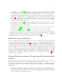
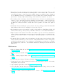
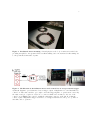
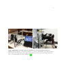
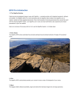
1
Supplementary Information S1
Traditional insect mounting
Figure 1 shows insects mounted horizontally with a pin going through the body from the back. This
mounting technique gives a strong hold on the insect body and facilitate specimen handling but provides
limited access for 3D scanning.
Image processing and 3D reconstruction software
Software used for image processing and 3D reconstruction are:
• Helicon Focus [1] for multi-focus image stacking to extend depth of field. There are alternative
open-source software such as CombineZP [2] and Huggins & Enfuse [3]. However we found Helicon
easier to use and able to exploit multi-core processing.
• 3DSOMTM software [4] for 3D reconstruction from multiple view images based on visual hull technique. The 3D reconstruction pipeline used by 3DSOMTM is described in [5]. There are other
3D reconstruction software including commercial software Agisoft Photo Scan [6]; and open-source
softwares Bundler [7] and Patch-based Multi-view Stereo [7, 8], and visual hull mesh software [9].
These two off-the-shelf software packages, together, cost around AUD1700 based on 2013 prices.
Image acquisition equipment
We use the following off-the-shelf components:
• A GigaPanTM Panorama Robot EPIC 100 [10]. Normally this device is used to control the tilt and
pan of a camera to capture panorama images. In this project, we turn it side-ways and use it as
a two-axis turntable to control the tilt and pan of the specimen to be imaged. The GigaPanTM
Panorama Robot connects to a camera via a cable and triggers a camera to capture one or more
images per rotation angle.
• A CanonTM 600D camera or better. It provides low-noise, high resolution images (18MP). It is
highly customizable with several ports for external trigger input, flash trigger output, and a USB
port for remote tethering. One problem with many DSLR cameras is that they rely on a mechanical
shutter which can cause mechanical vibration and image blur. The image blur due to mechanical
shutter vibration can be alleviated by using a camera flash triggered between shutter movement.
• A CanonTM EF 100mm macro lens for normal-mode and CanonTM MP-65mm for macro mode.
The EF-100mm lens provides magnification of 1× or smaller, while the MP-E 65mm lens provides
magnification from 1× to 5×. These macro lenses also have much less optical distortion than
some other lenses. A low-cost solution to make normal lens achieve higher magnification is to add
a macro extension tube between the camera and the lens. However this often increases optical
distortions [11]. The depth of field of MP-65mm lens as function of magnification and aperture can
be obtained from its user manual.
• A ViltroxTM JY-670 macro ring flash [12]. This flash provides illumination and reduces exposure
time. Short exposure time is critical for macro photography to reduce image blurring due to
vibration from the camera’s mechanical shutter. Additionally, a Tronix SpeedFire flash power
supply [13] is used for fast flash charging.
2
• A StackShotTM macro-rail [14]. This device enables us to capture high-magnification partiallyfocused images at predetermined depth intervals with high position accuracy. This macro-rail can
run automatically to capture images along a single direction. The process of movement and image
acquisition using macro-rail starts with a press of “Up” button on the rail’s control panel. To
synchronize StackShotTM macro-rail and GigaPanTM robot, we built a circuit interface, shown in
Figure 2, to convert the robot’s trigger signal to a press-button effect. The step size of the rail is set
to be approximately 70% of the depth of field of the macro lens to allow for adjacent overlapping
required for stacking multi-focus images.
• Two 1mW laser pointers [15] for specimen alignment. The laser beams are used to locate the
specimen at the center of rotation of the two-axis turntable so that the specimen stays at the same
position while being rotated and imaged.
• Aluminium frames [16] to hold the turntable, laser pointers, camera, and macro-rails in position.
• Button magnets [17], plastic spacers [18], epoxy glue and pins to mount insect specimens.
The system does not need any special software for acquiring images. The EOS Utility software
accompanying the camera is needed to remote-tether the camera and transfer images to a computer
during image acquisition. Based on 2013 prices, we estimate the total hardware to cost around AUD3200
to AUD5600. Examples of actual acquisition setups are shown in Figure 3.
Estimation of processing time
The reconstruction process described in this paper is a proof of concept and not yet optimized for speed
and for large-scale digitization. A time estimation for each stage of the 3D reconstruction procedure for
the insects shown in paper is provided in Table 1. The longhorn beetle, Christmas beetle and Amycterine
ground weevil take relatively similar amount of time to obtain a 3D model. The sand wasp has increased
reconstruction time due to the extra time required to manually correct the errors of background removal
around the wings, and to refine camera pose during reconstruction (hairs significantly increase the time
for pose refinement). The granary weevil, due to its small size, takes much more time to mount using
a microscope, acquire multi-focus images and perform 3D reconstruction. It is often the case that the
reconstruction stage is repeated several times to find and fix errors in background removal, or to iterate
the refinement process until the result is acceptable. Therefore, the times provided in Table 1 should
only be considered as indicative.
Informal feedback on using a 3D insect model for species identification
One possible use case for 3D insect models is species identification. In drafting this paper, we needed to
fully identify the Christmas beetle. We asked CSIRO entomologist Mr Tom Weir to try to do so from
the photograph, the 3D model, and finally the actual specimen. In addition to identifying the specimen
as a male Anoplognathus viriditarsus from the 3D model alone, Mr Weir provided feedback which we
summarize as:
• The single top-view photograph does not capture the key features needed to identify the species,
just enough information to determine its genus. The features are located at different parts of the
insects such as abdomen, head, mouth, claws, rear end, etc. Multiple images captured at particular
angles are required to show all these features.
3
• The 3D model provides useful extra information and allows views from any angle. There are still
missing features such as the mouth area and hairy surface on the head/nose due to resolution of
geometries and texture colours. However the available features are roughly enough to identify its
species. Examination and species identification would be facilitated if the texture information was
provided more clearly, or high-resolution images of the features were attached to the model.
• The actual specimen obviously provides all the information needed but needs examination under
a microscope for some features such as the mouth area and hair surface on the head. However,
out-of-focus effect and other physical restrictions makes the use of microscope to view the actual
specimen more cumbersome than to view the 3D model of specimen on a mobile device (such as
iPad).
• Identification involves matching the given specimen to its corresponding specimen in the Australian
National Insect Collection and comparing it to closely related species.
• For identification purposes, the natural-colour 3D model is much more helpful than the Micro CT
3D model. The better geometry accuracy of the Micro CT model does not assist in this instance.
• Higher resolution of the natural-colour 3D model is desirable to provide details of key identification
features. This is particularly important for features, such as hairs, that never get included in the
3D models. One solution would be to attach high resolution photographs to locations of the key
features.
• To make the 3D model useful for species identification, it is important to know in advance all key
features and the identification procedure and level. Ideally, this information would be arranged in a
way that directly supports fast, correct identification. 3D visualization and annotation could make
the identification procedure more obvious that the instructions currently provided in text and 2D
illustrations.
References
1. HeliconSoft (2013). Helicon Focus. URL http://www.heliconsoft.com/heliconsoft-products/
helicon-focus/.
2. Hadley A (2010). CombineZP. URL http://www.hadleyweb.pwp.blueyonder.co.uk/CZP/News.
htm.
3. D’Angelo P (2013). Hugin & Enfuse. URL http://hugin.sourceforge.net/tutorials/index.
shtml.
4. Creative Dimension Software Ltd (2013). 3DSOM. URL http://www.3dsom.com.
5. Baumberg A, Lyons A, Taylor R (2005) 3D S.O.M.A commercial software solution to 3D scanning.
Graphical Models 67: 476–495.
6. Agisoft (2013). Agisoft PhotoScan. URL http://www.agisoft.ru/.
7. Snavely N (2010). Bundler: Structure from Motion (SfM) for Unordered Image Collections. URL
http://www.cs.cornell.edu/~snavely/bundler/.
8. Furukawa Y (2010). Patch-based Multi-view Stereo Software. URL http://www.di.ens.fr/
pmvs/.
4
9. Forbes K (2009). Visual Hulls from Uncalibrated Snapshots. URL http://www.dip.ee.uct.ac.
za/~kforbes/DoubleMirror/DoubleMirror.html.
10. GigaPan Systems (2013). The GigaPan Store - Products, software and accessories to create gigapixel panoramas. URL http://gigapan.com/cms/shop/store.
11. McHugh S (2013).
Macro extension tubes and close-up lenses.
URL http://www.
cambridgeincolour.com/tutorials/macro-extension-tubes-closeup.htm.
12. JVC Technology (2013). Viltrox JY-670 macro ring lite. URL http://www.viltrox.com/en/
Products/flashlight/2012/1121/2.html.
13. Innovatronix Inc (2013). Tronix SpeedFire. URL http://www.innovatronix.com/index.php/
products/item/35-tronix-speedfire.
14. Cognisys Inc (2013). StackShot - Focus stacking macro rail. URL http://www.cognisys-inc.
com/stackshot/stackshot.php.
15. Dick-Smith (2013). Keychain 1mW Laser Pointer. URL http://www.dicksmith.com.au/
office-accessories/keychain-1mw-laser-pointer-dsau-xp0671.
16. Bunnings (2013). Castor Cup Round Tic 48mm Clear Plastic 25685. URL http://www.bunnings.
com.au/castor-cup-round-tic-48mm-clear-plastic-25685_p4050109.
17. Frenergy Magnets (2013). Neodymium Disc Magnet 10mm dia. x 3mm height N50. URL http:
//www.frenergy.com.au/products/Disc-10mm-dia.-x-3mm-height-N50.html.
18. Bunnings
(2013).
Metalmate
RCR
25.4
x
25.4
x
1.2mm
1m
Aluminium
Square
Box
Tube.
URL
http://www.bunnings.com.au/
metalmate-rcr-25-4-x-25-4-x-1-2mm-1m-aluminium-square-box-tube_p1067815.
19. Nguyen C, Adcock M, Lovell D, Mantle B, La Salle J (2014). Insect collections going 3D.
doi:10.4225/08/531FE0104C11A. URL http://dx.doi.org/10.4225/08/531FE0104C11A. Viewable at http://www.youtube.com/watch?v=THvfu6shJjg&list=UUak3NZxjNnWip327vYL8RLA or
http://publish.viostream.com/play/xbz189zsuhn8.
Figure Legends
Tables
Table 1. Time consumption estimation
Insect
Longhorn beetle,
Christmas beetle
and ground weevil
Sand Wasp
Granary Weevil
Mounting (min)
5
Acquisition (min)
15
Reconstruction (min)
60
5
30
15
180
120
120
5
Figure 1. Traditional insect mounting. A metal pin pierces the body of an insect from the back
providing stronghold to the specimen. However this mounting can be inconvenient for 3D scanning due
to the speciment’s horizontal body axis.
Figure 2. Modification of StackShotTM macro-rail’s control box to accept external trigger.
A) Circuit diagram to provide interface between trigger output of GigaPanTM robot and StackShotTM
control box. The resistor and the opto-coupler convert the trigger signal to a “press button” action. B)
the resistor and opto-coupler are soldered to a connector which can be mounted to the case of the
control box. C) Finished the control box with the extra input connector on the left. Note that the
connector pins of GigaPanTM trigger cable have to be swapped such that red cable goes to position 2
and white cable to position 3.
6
Figure 3. Examples of actual set-up in normal-mode (A) and macro-mode (B). The
GigaPanTM Panorama Robot is mounted sideways to act as a two-axis turntable. The camera is turned
900 around optical axis so that it can capture images that better fit the specimen and the mat target.
Video of the system (B) at work are available at [19].