1
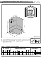
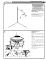
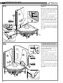
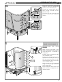
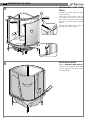
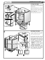
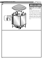
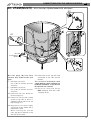
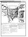
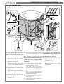
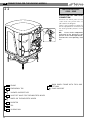
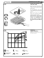
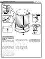
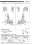
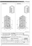
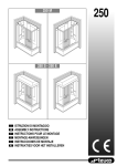
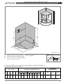
GB
PRE-INSTALLATION CARD ART. 252M (mm 1400 x 1400)
80
11
80
00
350
1860
2090
12
00
14
14
0
50
10
14
40
-
N.B. Installation must take place once floors and
Hot water connection for 1/2" tap fittings
walls are completed.
Cold water connection for tap fittings 1/2"
Connection for drainage pipe recessed in floor 1 1/2"
Electrical connection for Hydromassage IPX4
(box with cable press PG 13.5)
Siphon
97
C
F
O
CA
Ø 40
Measurements in mm.
160
The electrical installation must comply with the safety regulations for bathroom installation, as
described in the enclosed user’s manual.
ART. 252 M
Hydromassage
Net Water
Floor Delivery Delivery
Weight Content(1) Load
Weight Volume Vers.
Water
Air
Vert.
lt.
Kg/m2
Kg.
Kg.
m3
No. Jets Capacity Capacity Jets
172
245
269
283
ELECTRICAL
CHARACTERISTICS(2)
HYDRAULIC CHARACTERISTICS
3
Top 8
400
l/min.
280
l/min.
6
Multifunctions
Foot
Jets
2
Back Capacity Min.Max.
Jets
l/min Pressure
3
9 ÷16
2 ÷5
bar
Supply
Drain
Conn.
Whirlpool
Art.
Electropump
Kw
Installed Power
Kw
1/2"
11/2"
2WTX28
0,9
1,35
(1) - At overflow level
(2) - Before connecting the appliance, make sure that the voltage indicated on the rating plate is the same as that of the electric mains.I
The information and characteristics shown do not bind Teuco Guzzini srl who reserves the right to make any modifications it retains necessary without any prior warning or notice of replacement.
17
GB PRE-INSTALLATION CARD ART. 252S - 252E (mm 1400 x 1400)
20
12
80
11
2300
12
00
00
14
350
1860
1950
80
14
0
50
10
14
40
-
Hot water connection for 1/2" tap fittings
Cold water connection for tap fittings and sauna 1/2"
Connection for drainage pipe recessed in floor 11/2"
Electrical connection for Hydromassage IPX5
(box with cable press PG 13,5)
CA1 - Electrical connection for sauna and Multifunctions
IPX4 (box with cable press PG 21)
N.B. Installation must take place once floors and
Siphon
walls are completed.
The room in wich the sauna is to be installed
should be at least 240 cm high for service and
maintenance purposes.
97
C
F
O
CA
Ø 40
Measurements in mm.
160
Electric connections must be effected in accordance with safety regulations for bathroom
installation as described in the enclosed instruction booklet.
ART. 252 S - 252 E
Hydromassage
Multifunctions
Water
Net
Floor Delivery Delivery
Weight Content(1) Load
Weight Volume Vers.
Water
Air
Vert. Foot Cent. Back Capacity Min.Max.
lt.
Kg.
Kg/m2
Kg.
m3 No. Jets Capacity Capacity Jets Jets Sh.He. Jets l/min Pressure
206
245
287
319
ELECTRICAL
CHARACTERISTICS (2)
HYDRAULIC CHARACTERISTICS
3
Top 8
400
l/min.
280
l/min.
6
2
1
3
9 ÷16
2 ÷5
bar
Whirlpool
Supply
Drain
Conn.
1/2"
11/2" 2WTX28 1,35
Art.
Kw
Sauna
Multifunctions
Art.
Kw
Min. Max
Kw
5NTX18
2,4÷5
-
5MTX18
2,4÷5
0,05
(1) - Overflow level.
(2) - Before connecting the appliance, make sure that the voltage indicated on the rating plate is the same as that of the electric mainsI
The information and characteristics shown do not bind Teuco Guzzini srl who reserves the right to make any modifications it retains necessary without any prior warning or notice of replacement.
18
ASSEMBLING THE CABIN GB
1
All screws and accessories which
are necessary for installation are in
the appropriate box
Bag (A) screws for steps
1 - 3 - 3a - 3b - 3c
12
70
PREPARING THE WALL FOR
INSTALLATION
2040
P
Drill the holes in the wall to fasten
the Hydroshower to the wall as indicated in the diagram.
Fasten the small bracket (P) to the
wall using a screw and fischer.
POSITIONING THE
BATHTUB
2
Remove the screw indicated by the
arrow in order to remove the front
panel.
Pull the bottom part of the panel
towards you so that the clips (Y)
come out of their respective
housings.
Loosen the nut beneath the frame
of the bathtub, remove the
protective brackets for the front
panel and then tighten the nut
once again.
Place the bathtub in the corner of
the bathroom and make sure it is
level by using the appropriate
adjustable feet.
Prepare the drain connection using
the trap supplied.
X
Y
19
GB ASSEMBLING THE CABIN
3a
ASSEMBLING THE BACK
PANELS
C1
B
C1
M5X25
Ø5
M5X25
Ø5-M5
C
4,2x60
Ø5
3b
Bag (D) - plastic accessories
M3x10
Ø4
C2
M
B
A
C1
M5X25
Ø5-M5
4,2X60
Ø5-M5
C
20
Move the shower base away from
the corner in order to proceed with
the subsequent assembly steps.
Remove the screw from the end of
the lower track.
Apply silicone to the end of the
track as shown in the diagram.
Place the back panel (B) onto the
shower base and insert the support
into the end of the bottom track.
Fasten the panel to the track with
the screw (C) removed earlier and a
washer.
Insert the screws with the washers
(C1) and then fasten the panel to
the bathtub with the appropriate
nuts (C1).
Fit the rubber doorstop (M) onto
the panel (A) and fasten it with the
screw and washer (C2).
Remove the screw from the end of
the lower track.
Apply silicone to the end of the
track as shown in the diagram.
Place the back panel (A) onto the
shower base and insert the support
into the end of the bottom track.
Fasten the panel to the track with
the screw (C) removed earlier and a
washer.
Insert the screws with the washers
(C1) and then fasten the panel to
the bathtub with the appropriate
nuts (C1).
ASSEMBLING THE CABIN GB
3c
Fasten the back panels (A) and (B)
together with the appropriate
screws, nuts and washers (C2).
Tighten the screws (C1), which
were already inserted into the
bathtub, firmly.
To install the taps onto the back
panel, consult the attached
manual.
M5
Ø5
M5x25
Ø5
C2
C2
A
M5
Ø5
B
M5x25
Ø5-Ø5
C2
C1
C1
C1
C1
C1
4
Bag (B) - screws for steps 4 - 5
INSTALLING THE SIDE
PANELS
C
B
C
A1
Ø5-M5
Apply silicone to the groove in the
track corresponding to the position
of the side panels, as indicated in
the diagram.
Carefully slide the side panels (A1)
into the bottom track.
Position the threaded pins on the
support for the side panel (A1) so
that they match up with the holes
on the back panel (A); if necessary,
use a 2.5 Allen wrench.
Check that the seal (!) fits properly
along the entire length of the side
panel support (A1).
Fasten side panel (A1) to the back
panel (A) with the appropriate nuts
and washers (C).
21
GB ASSEMBLING THE CABIN
5
INSTALLING
TRACK
C1
4,2x60
Ø5
4,2x60
Ø5
C1
THE
TOP
Remove the screws from the ends
of the top track.
Insert the track onto the ends of
the supports and fasten it to the
back panels using the screws and
washers (C1) that were removed
earlier.
Tighten the screws on the ends of
the side panel (A1) support.
A1
6
22
APPLYING SILICONE
Apply a NEUTRAL (NON ACETIC)
silicone so as to prevent water from
leaking between the back panel
and the bathtub.
ASSEMBLING THE CABIN GB
7
FITTING THE DOOR
Insert the track covers (V) and the
end-trim (Y) into the top and
bottom tracks.
Turn the nut (D) until it is flush
with the top of the “C” screw.
Mount the door, hooking the
wheels (P) with the spring support
onto the lower track
Lift the door up so that the top
wheels (N) slide into the track.
C
D
N
V
Y
Y
V
P
Y
V
CENTRING THE DOOR
8
K
D
M4x30
C
A
Fit the handle onto the door
support and tighten the screws (C).
Then insert the piece of trim.
Close the door and make sure that
the magnetic seals are aligned
along the entire length of the door.
In the event that the seals do not
come together - as in case (A) or
case (B) - adjust the top slide
assembly indicated by the arrow.
- Lift the door, grasping it by the
supports.
- Tighten the screw (D) until the
magnetic seals are aligned.
N.B. After adjusting the slide
assembly, lock the nuts (D) in
place, inserting the covers (K) with
the inner wings facing outwards.
B
23
GB ASSEMBLING THE CABIN
9
ONLY FOR ARTICLES
252S - 252E
MOUNTING THE SAUNA
DOME ONTO THE SHOWER
CABIN
G
G
24
Place the adhesive steam seal onto
the top edge of the back panels.
Position the sauna onto the shower
cabin, making sure not to damage
the water and electrical hoses
attached to it. Make sure that the
steam seal (G) remains turned
toward the inside of the shower
cabin and that the front edge of the
dome fits into the slot on the top
track.
CONNECTIONS FOR THE VARIOUS MODELS GB
Art. 252M(MULTI) - Multifunction Hydroshower with whirlpool
A2
11
A1
F
9
C
A3
F
9
10
D
10
9
C
8
8
4
10
Blue N
Yellow-Green
Brown P
4
11
10
CA
11
A4
4
Once the plugs (D) have been
removed, they should not be used
again.
C - Hot water connection.
Use a 90 cm flexible stainless
steel hose.
F - Cold water connection.
Use a 90 cm flexible stainless
steel hose.
A1 - Connection for hose 10 for the
back massage unit.
A4 - Connection for the tap with tube
4 mounted on the cabin and the
diverter.
The electrical installation must
comply with the safety regulations for
bathroom installation, as described in
the attached user’s manual.
CA - Electrical connection for the
IPX5 whirlpool (box with cable
clamp PG 13.5).
A2 - Connection for the both shower
system using tube 9, which is
supplied, and for tube 11 for the
foot massage unit.
A3 - Diagram for the water supply
connection for the model with a
thermostatic mixer.
When installing the shut-off
valve, pay special attention to the
direction of the arrow.
25
GB CONNECTIONS FOR THE VARIOUS MODELS
Art. 252S(TOP) - Top Multifunction Hydrosteam with whirlpool
A4
A1
2
2
3
2 1
11
5
9
F
9
A2
10
1
CA1
C
1
3
3
5
5
N Blue
Yellow green
P Brown
A5
D
F
9
8
C
10
Blue N
Yellow green
Brown P
CA
10
11
4
8
10
A3
4
11
A6
3
D
3
Once the plugs (D) have been A4 - Connection for hoses 1-2-3 for
removed, they should not be used
the sauna and hose 5 for the
again.
shower head with nebulizer.
NB:
Hoses 1 and 2 for the
C - Hot water connection.
decalcification
system must always be
Use a 90 cm flexible stainless
filled
with
water.
Therefore, this
steel hose.
system must not be emptied during
F - Cold water connection.
installation.
Use a 90 cm flexible stainless
steel hose and a union T for the A5 - Diagram for the water supply
connection for the model with
water supply to the sauna.
and a thermostatic mixer.
A1 - Connection for the shower system
When installing the shut-off
using hose 9, which is supplied,
valve, pay special attention to the
and for hose 11 for the foot masdirection of the arrow.
sage.
A6 - Connection for the tap with tube
A2 - Connection for hose 10 for the
4 mounted on the cabin and the
back massage unit.
diverter.
A3 - Connection for hose 3 (to the
drain pipe).
26
4
The electrical installation must
comply with the safety regulations for
bathroom installation, as described in
the attached user’s manual.
CA - Electrical connection for the
IPX5 whirlpool (box with cable
clamp PG 13.5)
CA1 - Electrical connection for the
IPX4 sauna (box with cable
clamp PG 21)
CONNECTIONS FOR THE VARIOUS MODELS GB
Art. 252E(PLUS)
A4
Plus Multifunction Hydrosteam with whirlpool
2
A1
2
5 3
2
11
1
F
9
1
3
CA1
C
3
5
5
N Blue
Yellow green
P Brown
A5
A2
2
1
F
C
11
10
Blue N
Yellow green
Brown P
1
CA
11
10
A3
4
A6
3
A7
10
D
10
Once the plugs (D) have been A4 - Connection for hoses 1-2-3 for
the sauna and hose 5 for the
removed, they should not be used
shower head with nebulizer.
again.
NB:
Hoses 1 and 2 for the
C - Hot water connection.
decalcification
system must always be
Use and a 60 cm flexible
filled
with
water.
Therefore, this
stainless steel hose.
system must not be emptied during
F - Cold water connection.
installation.
Use and a 80 cm flexible
stainless steel hose and a and a A5 - Diagram for the water supply
connection for the model with
union T for the water supply to
and a thermostatic mixer.
the sauna.
Use and a 60 cm flexible
A1 - Connection for the shower system
stainless steel hose (F) and a 80
using hose 9, which is supplied,
cm flexible stainless steel hose
and for hose 11 for the foot mas(C).
sage.
When installing the shut-off
valve, pay special attention to the
A2 - Cleaning the taps with filter.
direction of the arrow.
A3 - Connection for the electrical wire
from the sauna to the wire from A6 - Connection for hose 3 (to the
drain pipe).
the power unit.
A7 - Connection for hose 10 for the
back massage unit.
3
The electrical installation must
comply with the safety regulations for
bathroom installation, as described in
the attached user’s manual.
CA - Electrical connection for the
IPX5 whirlpool (box with cable
clamp PG 13.5)
CA1 - Electrical connection for the
IPX4 sauna (box with cable
clamp PG 21)
27
GB CONNECTIONS FOR THE VARIOUS MODELS
11
ONLY FOR ARTICLES
252S - 252E
EQUIPOTENTIAL EARTHING
CONNECTION
Connect the metal parts of the
cabin with the yellow wire as
indicated in the diagram.
There is and a terminal at point (1)
for the equipotential connection of
the other grounds present in the
room.
NB:
If one of the components
indicated in the diagram is not
present on the model purchased,
insulate the corresponding “fast
on”.
1
2
3
4
5
6
7
8
9
10
28
1
FRAME
2
EMERGENCY TAP
3
SHOWER SUPPORT ROD
4
SHUT-OFF VALVE FOR THERMOSTATIC MIXER
5
MIXER OR THERMOSTATIC MIXER
6
DIVERTER
7
TAP
8
SLIDING RAIL
BACK PANEL FRAME WITH TAPS AND
FITTINGS
10 PUMP SUPPORT
9
ASSEMBLING THE CABIN GB
12
USING THE SHOWER FOR
THE FIRST TIME
Once all of the connections are
made and before fastening the
cabin to the wall, remove all of the
adhesive tags.
Run the regeneration and a sauna
cycle, following the instructions
contained in the attached user’s
manual.
Make sure that there are no water
leaks in the connections and that
everything operates normally.
If the first time the sauna system is
turned on the control panel
displays the “DIAGNOSIS 9”
message, remove the grate and
press the button for resetting the
thermostat, indicated with the
arrow.
13
HYDRAULIC
CHARACTERISTICS
l/min
Diagram of the mixed water flow for
the various features.
15
10
5
0
1
2
3
4
5
Bar
Vertical
massage
Back
massage
Foot
massage
Overhead fixed
shower with
nebulizer
Shower
massage
Spout from
overflow
29
GB ASSEMBLING THE CABIN
14
C1
T1
M5x16
Ø5-M5
M5x16
Ø5
C2
T2
C4
4,2x38
Ø5
Y
T
X
Ø8
Bag (C) - screws for step 14
FIXING THE SHOWER TO
THE WALL
If the unit is equipped with and a
sauna, you must lift the dome and
insert a spacer between the track
and the dome itself in order to fix
the cabin definitively.
Move the cabin to the wall, position
the bracket (T1) on the frame, drill
a hole in the wall, insert the screw
with the fischer and fasten the
bracket (T1) to the frame,
tightening the screw with the
washer (C1).
Insert the corner bracket (T2) into
the bracket on the wall and fasten
it with the screw and washer (C2).
Fit the side panel by sliding it
down from the top so as to hook it
onto the support bracket on the
frame.
30
Fix the side panel by mounting the
towel-knob with the screws and
washers (C2); insert the trim.
Fix the bathtub to the floor with
plates (T), screws and fischers.
Re-install the bathtub panel by
inserting the top edge underneath
the bathtub and pressing the clips
(Y) so that they go back into their
respective housings; fasten the
panel with the screw which was
removed previously.
ONLY FOR ARTICLE 252E
Connect the cable (S) to the
control panel located on the side
panel.