1
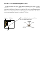
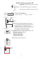
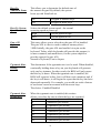
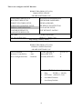
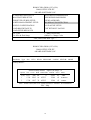
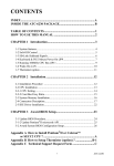
CONTENTS
INDEX .......................................................................................... A
HOW TO USE THIS MANUAL……………………………….2
INTRODUCTION TO THE ATC-6510 MAINBOARD
HARDWARE……………………………………………………3
INSIDE THE ATC-6510 MAINBOARD PACKAGE………...4
CHAPTER 1
Introduction…………………………………..5
1-1 Soft-Off-Control..............................................................................5
1-2 LDCM ( LANDesk Client Manager, option) ............................... .6
1-3 Thermister (option)........................................................................ .7
1-4 Wake-On-LAN.............................................................................. .7
1-5 SB-Link Sideband Signals (JP3)…………………………………8
CHAPTER 2
Installation....................................................... 9
2-1 Installation Procedure ................................................................. .9
2-2 CPU Installation............................................................................ .10
2-3 System Memory Installation……………………………………..16
2-4 Connectors Description................................................................. .17
2-5 IDE Driver Installation ................................................................. .22
CHAPTER 3
Award BIOS Setup ......................................... 23
3-1 Update BIOS Procedure................................................................ .24
3-1-1 Update Pentium II microcode API…………………………….25
3-2 Award System BIOS Configuration Setup ................................... .26
Appendix A ……………………………………………………..56
Appendix B How to Install Pentium II CPU ? &
How to Install Celeron CPU ?
Appendix C How to Setup Thermister (option) ?
HOW TO USE THIS MANUAL
1
To obtain maximum use from this manual it is suggested:
Read Page A COMPONENT LOCATION DIAGRAM where you find the
mainboard layout diagram. Please refer to it when you configure the system.
Read about an overview of the mainboard features, packing contents, and how to
upgrade as well as to change hardware configurations such as memory size, CPU type,
jumper settings lists and connectors in the following categories:
INTRODUCTION TO THE ATC-6510 MAINBOARD HARDWARE
INSIDE THE ATC-6510 MAINBOARD PACKAGE
Chapter 1 Introduction
Chapter 2 Installation
When you have finished reading of both chapter 1 and chapter 2, turn to Chapter 3
Award BIOS Setup where you will find the update BIOS procedure and the further
information which is stored in the SETUP is the system hardware configuration.
The back of this manual contains APPENDIX A which is a list of request form for
technical support, APPENDIX B which shows you how to setup Pentium II CPU and
APPENDIX C which shows you how to setup thermister.
Your system dealer will set up the mainboard according to your demand of the
computer. It means that the current settings of your mainboard may not be the same as
the defaults shown in this user's manual. If you need to change your configuration,
please ask your dealer first. Be sure this will not void your system warranty, or ask
your dealer to do it for you.
REMARK
Intel® is a registered trademark of Intel Corporation.
All other brands and product names are trademarks registered trademarks of their respective companies.
INTRODUCTION TO THE ATC-6510 MAINBOARD
2
HARDWARE
Each ATC-6510 mainboard supports or contains the following components:
! INTEL Pentium II CPU operating from 233MHz up to 333MHz.
! INTEL CeleronTM CPU operating from 266MHz up to 333MHz.
! INTEL 440EX PCIset.
! ATI AGP Rage IIC 3D VGA chipset.
! Yamaha 719/715 IIC 3D stereo sound PnP chipset, optional for ATI AGP Rage
Pro 3D.
! Using two 168-pin DIMM sockets, provides two banks of 64-bit wide path up to
256MB SDRAM or 256 EDO DRAM (with parity chip ECC support).
! Built-in Switching Voltage Regulator.(VRM 8.2 SPEC.)
! INTEL LDCM software.(option)
! Supports auto-detect CPU core voltage range 1.8V to 3.5V.
! Supports one AGP slot, three PCI slots with revision 2.1 interface compliant and
one 16-bit ISA slot.
! Dual Master IDE connectors support Ultra DMA/33, up to four devices in two
channels for connecting of high capacity hard drive, CD-ROM disk drive, tape
backup etc..
! Supports the USB (Universal Serial Bus) connector.
! PS/2 keyboard connector and PS/2 mouse connector.
! Winbond 83977 high-speed Ultra Multi-I/O chipset.
! Supports Infrared transfer (IrDA TX/RX) connection.
! One FDC port supports two devices up to 2.88MB.
! Two 16550A fast UARTs compatible serial ports.
! One EPP/ECP mode parallel printer port.
! Built-in Hardware Health Monitoring. (option)
! Built-in SGRAM optional for 2MB, 4MB, 8MB; default value is 4MB.
! Hardware Dimension is 244mm x 244mm. (9.6" x 9.6")
INSIDE THE ATC-6510 MAINBOARD PACKAGE
3
The mainboard comes securely packed in a durable box and shipping carton. If any of
the following items are missing or damaged, please contact your supplier.
Each mainboard contains:
Description
Q'TY
1
Mainboard
: ATC-6510.
1
Retention mechanism (for Pentium II installation)
1
CD(option)
: LDCM, Enhanced IDE driver
Award system BIOS Update Utility
1
Diskette(option)
: Enhanced IDE driver
Award system BIOS Update Utility
1
Cable
: Thermister cable (option).
1
Cable
: Enhanced IDE cable.
1
Cable
: F.D.D. cable.
1
Manual
: User manual. (English version)
1
English LDCM user manual (option)
CHAPTER 1 INTRODUCTION
4
The ATC-6510 mainboard has ATI AGP Rage IIC 3D VGA chipset, Yamaha
719/715 IIC 3D stereo sound PnP chipsets and SGRAM (option) onboard. The ATI
AGP Rage IIC 3D VGA chipset using AGP interface technique which allows users
could have 3D display resolution without plug any of VGA cards and the Yamaha
719/715 IIC 3D stereo sound PnP chipset using ISA interface which could let your
system has 3D stereo sound. With 2MB SGRAM onboard, the mainboard can play
large volume games. If your mainboard built-in 4MB SGRAM, your system can
perform more powerful gamers e.g. 3D games. The 8 SGRAM onboard is to provide
users who need running volume CAD software.
1-1 SOFTWARE POWER OFF CONTROL
The mainboard design supports Software Power Off Control feature through the
SMM code in the BIOS under Windows 95, and MS-DOS operation system
environment. This is Intel ATX form factor feature and you should use ATX power
supply.
First, you should connect the power switch cable (provided by the ATX case
supplier) to the connector “PS-ON” on the mainboard. In the BIOS screen of
POWER MANAGEMENT SETUP’, choose “User Defined” (or “Min. Power Saving”
or “Max. Power Saving”) in ‘Power Manager’ and choose “Yes” in ‘PM Control by
APM’.
In Windows 95, if you would like to power off the system, you just choose
“shutdown the computer ?” in the “Shut Down Windows“ from Windows 95, then the
system power will be off directly, and become the stand-by status. You will find the
power LED light is not blinking (see the table below for the operating status). If
you would like to restart the system, just press the power switch button, and the
system will be powered on.
Note : If you will leave your system for several days, we suggest you use hardware
power off to shutdown your system.
Status
Software power off
control
APM mode
System running
Power LED Light
Light off
Turbo LED Light
Light off
Blinking
Light on
Light on
Light on
1-2 LDCM (LANDesk Client Manager)(option)
5
ATC-6510 built-in controller(option) support Intel LDCM. LDCM can satisfy
users who want manageable systems that can interact automatically with the user.
Client manager is the answer, enabling both administrators and clients to manage
systems. The features of LDCM are as following :
※ View system inventory
Client Manager enables you to view hundreds of inventoried items. Some of these
items are software related, while many others are hardware related.
※ View DMI-compliant component information
Client manager enables you to view component information that is compliant with the
Desktop Manager Interface(DMI). This means you can manage third-party DMIcompliant components not included with Client manager.
※ Back up and restore system configuration files.
Client Manager enables you back up and restore system configuration files. Whenever
you plan on changing the system configuration , you can make a backup set. If the
system no longer works correctly, after you change the system configuration , you
can simply restore the system configuration with the backup set.
※ Troubleshoot
Since Client manager enables you to view the system inventory, you can easily
troubleshoot system problems.
※ Receive notifications for system events
Client manager enables you to receive notification of certain system events. For
example, if the system is running low on virtual memory, you are notified of the
potential problem.
※ Transfer files to and from client workstations
As an administrator, you have the ability to transfer files to and from client
workstation. This is helpful, for example, when you need to update a client
workstation driver.
※ Remotely reboot client workstations
Administrator also have the ability to remotely reboot a workstation . This is helpful
when you want your system configuration settings to take effect.
6
1-3 Thermister (option)
This means that users can monitor the CPU temperature through thermister.
When setting up the thermister, the BIOS will load the CPU temperature automatically.
There is a choice of the warning beep sound if users set the option on. If the CPU
temperature overheated, users will get the notice from the thermister. This time you
should shut down computer and check your devices. Consequently, protecting and
monitoring the CPU temperature is the thermister’s job.
1-4 Wake-On-LAN
The remote Wake-On-LAN mode of operation is a mechanism that uses
Advanced Micro Device Magic Packet technology to power up a sleeping workstation
on the network. This mechanism is accomplished when the LAN card receives a
specific packet of information, called a Magic Packet, addressed to the node on the
network. For additional protection, Secure ON is an optional security feature that can
be added to the Magic Packet that requires a password to power up the sleeping
workstation. When the LAN card is in remote Wake-On-LAN mode, main system
power can be shut down leaving power only for the LAN card and auxiliary power
recondition.
The LAN card performs no network activities while in the remote
Wake-On-LAN mode of operation. It only monitors the network for receipt of a
Magic Packet. If a Magic Packet is addressed to the LAN card on the network, the
LAN card wake up the system. If the Secure ON feature has been enabled, the
password added to the Magic Packet is also verified prior to waking up the system.
WOL LAN card will provide a 3-pin line to connect the WOL connector on the
mainboard.
CAUTION :
For Wake-on-LAN, the +5V standby line for the power supply must capable of
Delievring +5V ±5% at 720mA. Failure to provide adequate standby current when
implementing Wake-on-LAN, can damage the power supply.
Before you enable Wake-on-LAN function, first check your power supply
specification to meet the above requirement or not.
7
1-5 SB-LINK Sideband Signals (JP3)
In order to migrate the legacy Sound Blaster compatible audio to the PCI bus,
EMU8008 incorporates a pair of SB-Link request/grant sideband signals (PCPCIR
EQ#A and PCPCISIRQ) to interface to the PCI bus. SB-Link is a mechanism that was
defined and developed by Creative as a docking solution which allows ISA slots to
exist in docking stations connected to desktop PC PCI bus.
ISA slot
PCI slots
JP3 2x3 sideband header, sound will also
has a 2x3 header and a cable.
REQ#A
JP 3
8
GND
GND
GNT#A
SIRQ
CHAPTER 2 INSTALLATION
2-1 INSTALLATION PROCEDURE
Before installing the computer, please prepare all components such as CPU, DRAM;
peripherals such as hard drive, keyboard, CD-ROM disk drive and accessories such as
cables. Then, install the system as following:
1. Plug CPU/ heat sink (refer to Pentium II installation guide, Appendix A), and
DRAM modules on the mainboard.
2. Set DIP switch based on your configuration.
3. Plug add-on cards into PCI/ISA slots, if needed.
4. Connect cables to peripherals, specially for VGA and Sound connector.
5. Make sure all components and devices are well connected, turn on the power and
setup System BIOS based on your configuration.
6. Install peripherals, add-on card drivers and test them.
7. If all of above procedures are success, turn-off the power then plug all of them into
your computer case.
Remark :
Before you do the mainboard installation, please keep in mind that VGA
and Sound chipsets are built-in on the ATC-6510 mainboard along with
MicroATX Form Factor.
9
2-2 CPU INSTALLATION
The 6510 mainboard supports both INTEL Pentium II CPU and Celeron CPU.
2-2-1 CPU TYPE SELECTION (by BIOS)
1.Press the <Del> key when the system is booting up.
2.The following main menu will appear.
ROM PCI/ISA BIOS (ATC-6510)
CMOS SETUP UTILITY
AWARD SOFTWARE, INC.
STANDARD CMOS SETUP
INTEGRATED PERIPHERALS
BIOS FEATURES SETUP
CHIPSET FEATURES SETUP
POWER MANAGEMENT SETUP
PNP/PCI CONFIGURATION
LOAD BIOS DEFAULTS
LOAD SETUP DEFAULTS
SUPERVISOR PASSWORD
USER PASSWORD
IDE HDD AUTO DETECTION
SAVE & EXIT SETUP
EXIT WITHOUT SAVING
ESC: Quit
F10: Save & Exit Setup
#$%&:Select Item
(Shift) F2 : Change Color
AT Clock, DRAM Timings, .......
3.
Select “ CHIPSET FEATURES SETUP ”
STANDARD CMOS SETUP
BIOS FEATURES SETUP
CHIPSET FEATURES SETUP
POWER MANAGEMENT SETUP
PNP/PCI CONFIGURATION
LOAD BIOS DEFAULTS
LOAD SETUP DEFAULTS
INTEGRATED PERIPHERALS
SUPERVISOR PASSWORD
USER PASSWORD
IDE HDD AUTO DETECTION
SAVE & EXIT SETUP
EXIT WITHOUT SAVING
ESC: Quit
F10: Save & Exit Setup
#$%&:Select Item
(Shift) F2 : Change Color
AT Clock, DRAM Timings, .......
10
4. Then the following screen will appear.
ROM PCI/ISA BIOS (ATC-6510)
CHIPSET FEATURES SETUP
AWARD SOFTWARE, INC.
Auto Configuration
DRAM Speed Selection
MA Wait State
EDO RAS# To CAS# Delay
EDO RAS# Precharge Time
EDO DRAM Read Burst
EDO DRAM Write Burst
CPU-To-PCI IDE Posting
System BIOS Cacheable
Video BIOS Cacheable
Video RAM Cacheable
8 Bit I/O Recovery Time
16 Bit I/O Recovery Time
Memory Hole At 15M-16M
Passive Release
Delayed Transaction
AGP Aperture Size (MB)
SDRAM RAS-to-CAS Delay
SDRAM RAS Precharge Time
: Enabled
: 60 ns
: Slow
:3
:3
: x333
: x222
: Disabled
: Disabled
: Disabled
: Disabled
:3
:2
: Disabled
: Enabled
: Disabled
SDRAM CAS latency Time
CPU Clock Ratio
Auto Detect DIMM/PCI ClK
CPU Clock Frequency
Spread Spectrum Modulated
:3
: 2.0x
: Enabled
: 66MHz
: Disabled
*Following menus are
optional*
*CPU Warning Temperature
*Current System Temperature
*Current CPU Temperature
*Current ChassisFAN Speed
*Current PWRFAN Speed
*Current CPUFAN Speed
*Vcore : 2.80V
VTT(V)
*+3.3V : 3.45V
+5V
*+12V : 12.22V
–12V
*-5V : -5.16V
: Disabled
: 20 o C/ 68 o F
: 20 o C/ 68 o F
: 0 PRM
: 0 PRM
: 0 RPM
: 1.47V
: 4.91V
: -11.76
: 128
: Slow
: Slow
Esc: Quit
#$%&:Select Item
F1 : Help
PU/PD/+/-:Modify
F5 : Old Values
(Shift)F2 :Color
F6 :Load BIOS Defaults
F7 :Load Setup Defaults
※※ NOTE
If an incorrect CPU frequency is set through the BIOS, a system failure may
occur. This system failure can be solved by pressing the “Insert” key on the
keyboard to clear up the previous set frequency (i.e. back to 133MHz (66MHz x 2.0)
or the default frequency), and then the power button to restart the system and reset
the value in BIOS screen. Or user can clear CMOS to reset the BIOS value.
Also the ATC-6510 mainboard supports keyboard power on or
mouse power on function, (refer to ‘Integrated Peripherals’, page48,49).
When you set ‘keyboard power on’, you can select set password or not.
When you set password, you should key-in the password to power on
the system. If you forget the password, you should clear CMOS to reset
the system.
11
5a. Intel Pentium II 233MHz (66 x 3.5)
ROM PCI/ISA BIOS (ATC-6510)
CHIPSET FEATURES SETUP
AWARD SOFTWARE, INC.
Auto Configuration
: Enabled
SDRAM CAS latency Time
:3
DRAM Speed Selection
MA Wait State
EDO RAS# To CAS# Delay
EDO RAS# Precharge Time
EDO DRAM Read Burst
EDO DRAM Write Burst
CPU-To-PCI IDE Posting
System BIOS Cacheable
Video BIOS Cacheable
Video RAM Cacheable
8 Bit I/O Recovery Time
16 Bit I/O Recovery Time
Memory Hole At 15M-16M
Passive Release
Delayed Transaction
: 60 ns
: Slow
:3
:3
: x333
: x222
: Disabled
: Disabled
: Disabled
: Disabled
:3
:2
: Disabled
: Enabled
: Disabled
CPU Clock Ratio
Auto Detect DIMM/PCI ClK
CPU Clock Frequency
Spread Spectrum Modulated
: 3.5x
: Enabled
: 66MHz
: Disabled
*Following menus are
optional*
*CPU Warning Temperature
*Current System Temperature
*Current CPU Temperature
*Current ChassisFAN Speed
*Current PWRFAN Speed
*Current CPUFAN Speed
*Vcore : 2.80V
VTT(V)
*+3.3V : 3.45V
+5V
*+12V : 12.22V
–12V
*-5V : -5.16V
: Disabled
: 20 o C/ 68 o F
: 20 o C/ 68 o F
: 0 PRM
: 0 PRM
: 0 RPM
: 1.47V
: 4.91V
: -11.76
AGP Aperture Size (MB)
SDRAM RAS-to-CAS Delay
SDRAM RAS Precharge Time
: 128
: Slow
: Slow
Esc: Quit
#$%&:Select Item
F1 : Help
PU/PD/+/-:Modify
F5 : Old Values
(Shift)F2 :Color
F6 :Load BIOS Defaults
F7 :Load Setup Defaults
12
5b. Intel Pentium II 266MHz (66 x 4.0)
ROM PCI/ISA BIOS (ATC-6510)
CHIPSET FEATURES SETUP
AWARD SOFTWARE, INC.
Auto Configuration
: Enabled
SDRAM CAS latency Time
:3
DRAM Speed Selection
MA Wait State
EDO RAS# To CAS# Delay
EDO RAS# Precharge Time
EDO DRAM Read Burst
EDO DRAM Write Burst
CPU-To-PCI IDE Posting
System BIOS Cacheable
Video BIOS Cacheable
Video RAM Cacheable
8 Bit I/O Recovery Time
16 Bit I/O Recovery Time
Memory Hole At 15M-16M
Passive Release
Delayed Transaction
: 60 ns
: Slow
:3
:3
: x333
: x222
: Disabled
: Disabled
: Disabled
: Disabled
:3
:2
: Disabled
: Enabled
: Disabled
CPU Clock Ratio
Auto Detect DIMM/PCI ClK
CPU Clock Frequency
Spread Spectrum Modulated
: 4.0x
: Enabled
: 66MHz
: Disabled
*Following menus are
optional*
*CPU Warning Temperature
*Current System Temperature
*Current CPU Temperature
*Current ChassisFAN Speed
*Current PWRFAN Speed
*Current CPUFAN Speed
*Vcore : 2.80V
VTT(V)
*+3.3V : 3.45V
+5V
*+12V : 12.22V
–12V
*-5V : -5.16V
: Disabled
: 20 o C/ 68 o F
: 20 o C/ 68 o F
: 0 PRM
: 0 PRM
: 0 RPM
: 1.47V
: 4.91V
: -11.76
AGP Aperture Size (MB)
SDRAM RAS-to-CAS Delay
SDRAM RAS Precharge Time
: 128
: Slow
: Slow
Esc: Quit
#$%&:Select Item
F1 : Help
PU/PD/+/-:Modify
F5 : Old Values
(Shift)F2 :Color
F6 :Load BIOS Defaults
F7 :Load Setup Defaults
13
5c. Intel Pentium II 300MHz (66 x 4.5)
ROM PCI/ISA BIOS (ATC-6510)
CHIPSET FEATURES SETUP
AWARD SOFTWARE, INC.
Auto Configuration
: Enabled
SDRAM CAS latency Time
:3
DRAM Speed Selection
MA Wait State
EDO RAS# To CAS# Delay
EDO RAS# Precharge Time
EDO DRAM Read Burst
EDO DRAM Write Burst
CPU-To-PCI IDE Posting
System BIOS Cacheable
Video BIOS Cacheable
Video RAM Cacheable
8 Bit I/O Recovery Time
16 Bit I/O Recovery Time
Memory Hole At 15M-16M
Passive Release
Delayed Transaction
: 60 ns
: Slow
:3
:3
: x333
: x222
: Disabled
: Disabled
: Disabled
: Disabled
:3
:2
: Disabled
: Enabled
: Disabled
CPU Clock Ratio
Auto Detect DIMM/PCI ClK
CPU Clock Frequency
Spread Spectrum Modulated
: 4.5x
: Enabled
: 66MHz
: Disabled
*Following menus are
optional*
*CPU Warning Temperature
*Current System Temperature
*Current CPU Temperature
*Current ChassisFAN Speed
*Current PWRFAN Speed
*Current CPUFAN Speed
*Vcore : 2.80V
VTT(V)
*+3.3V : 3.45V
+5V
*+12V : 12.22V
–12V
*-5V : -5.16V
: Disabled
: 20 o C/ 68 o F
: 20 o C/ 68 o F
: 0 PRM
: 0 PRM
: 0 RPM
: 1.47V
: 4.91V
: -11.76
AGP Aperture Size (MB)
SDRAM RAS-to-CAS Delay
SDRAM RAS Precharge Time
: 128
: Slow
: Slow
Esc: Quit
#$%&:Select Item
F1 : Help
PU/PD/+/-:Modify
F5 : Old Values
(Shift)F2 :Color
F6 :Load BIOS Defaults
F7 :Load Setup Defaults
14
5d. Intel Pentium II 333MHz (66 x 5.0)
ROM PCI/ISA BIOS (ATC-6510)
CHIPSET FEATURES SETUP
AWARD SOFTWARE, INC.
Auto Configuration
: Enabled
SDRAM CAS latency Time
:3
DRAM Speed Selection
MA Wait State
EDO RAS# To CAS# Delay
EDO RAS# Precharge Time
EDO DRAM Read Burst
EDO DRAM Write Burst
CPU-To-PCI IDE Posting
System BIOS Cacheable
Video BIOS Cacheable
Video RAM Cacheable
8 Bit I/O Recovery Time
16 Bit I/O Recovery Time
Memory Hole At 15M-16M
Passive Release
Delayed Transaction
: 60 ns
: Slow
:3
:3
: x333
: x222
: Disabled
: Disabled
: Disabled
: Disabled
:3
:2
: Disabled
: Enabled
: Disabled
CPU Clock Ratio
Auto Detect DIMM/PCI ClK
CPU Clock Frequency
Spread Spectrum Modulated
: 5.0x
: Enabled
: 66MHz
: Disabled
*Following menus are
optional*
*CPU Warning Temperature
*Current System Temperature
*Current CPU Temperature
*Current ChassisFAN Speed
*Current PWRFAN Speed
*Current CPUFAN Speed
*Vcore : 2.80V
VTT(V)
*+3.3V : 3.45V
+5V
*+12V : 12.22V
–12V
*-5V : -5.16V
: Disabled
: 20 o C/ 68 o F
: 20 o C/ 68 o F
: 0 PRM
: 0 PRM
: 0 RPM
: 1.47V
: 4.91V
: -11.76
AGP Aperture Size (MB)
SDRAM RAS-to-CAS Delay
SDRAM RAS Precharge Time
: 128
: Slow
: Slow
Esc: Quit
#$%&:Select Item
F1 : Help
PU/PD/+/-:Modify
F5 : Old Values
(Shift)F2 :Color
F6 :Load BIOS Defaults
F7 :Load Setup Defaults
15
5e. Intel CeleronTM CPU 266MHz (66 x 4.0)
ROM PCI/ISA BIOS (ATC-6510)
CHIPSET FEATURES SETUP
AWARD SOFTWARE, INC.
Auto Configuration
: Enabled
SDRAM CAS latency Time
:3
DRAM Speed Selection
MA Wait State
EDO RAS# To CAS# Delay
EDO RAS# Precharge Time
EDO DRAM Read Burst
EDO DRAM Write Burst
CPU-To-PCI IDE Posting
System BIOS Cacheable
Video BIOS Cacheable
Video RAM Cacheable
8 Bit I/O Recovery Time
16 Bit I/O Recovery Time
Memory Hole At 15M-16M
Passive Release
Delayed Transaction
: 60 ns
: Slow
:3
:3
: x333
: x222
: Disabled
: Disabled
: Disabled
: Disabled
:3
:2
: Disabled
: Enabled
: Disabled
CPU Clock Ratio
Auto Detect DIMM/PCI ClK
CPU Clock Frequency
Spread Spectrum Modulated
: 4.0x
: Enabled
: 66MHz
: Disabled
*Following menus are
optional*
*CPU Warning Temperature
*Current System Temperature
*Current CPU Temperature
*Current ChassisFAN Speed
*Current PWRFAN Speed
*Current CPUFAN Speed
*Vcore : 2.80V
VTT(V)
*+3.3V : 3.45V
+5V
*+12V : 12.22V
–12V
*-5V : -5.16V
: Disabled
: 20 o C/ 68 o F
: 20 o C/ 68 o F
: 0 PRM
: 0 PRM
: 0 RPM
: 1.47V
: 4.91V
: -11.76
AGP Aperture Size (MB)
SDRAM RAS-to-CAS Delay
SDRAM RAS Precharge Time
: 128
: Slow
: Slow
Esc: Quit
#$%&:Select Item
F1 : Help
PU/PD/+/-:Modify
F5 : Old Values
(Shift)F2 :Color
F6 :Load BIOS Defaults
F7 :Load Setup Defaults
16
5f. Intel CeleronTM CPU 300MHz (66 x 4.5)
ROM PCI/ISA BIOS (ATC-6510)
CHIPSET FEATURES SETUP
AWARD SOFTWARE, INC.
Auto Configuration
: Enabled
SDRAM CAS latency Time
:3
DRAM Speed Selection
MA Wait State
EDO RAS# To CAS# Delay
EDO RAS# Precharge Time
EDO DRAM Read Burst
EDO DRAM Write Burst
CPU-To-PCI IDE Posting
System BIOS Cacheable
Video BIOS Cacheable
Video RAM Cacheable
8 Bit I/O Recovery Time
16 Bit I/O Recovery Time
Memory Hole At 15M-16M
Passive Release
Delayed Transaction
: 60 ns
: Slow
:3
:3
: x333
: x222
: Disabled
: Disabled
: Disabled
: Disabled
:3
:2
: Disabled
: Enabled
: Disabled
CPU Clock Ratio
Auto Detect DIMM/PCI ClK
CPU Clock Frequency
Spread Spectrum Modulated
: 4.5x
: Enabled
: 66MHz
: Disabled
*Following menus are
optional*
*CPU Warning Temperature
*Current System Temperature
*Current CPU Temperature
*Current ChassisFAN Speed
*Current PWRFAN Speed
*Current CPUFAN Speed
*Vcore : 2.80V
VTT(V)
*+3.3V : 3.45V
+5V
*+12V : 12.22V
–12V
*-5V : -5.16V
: Disabled
: 20 o C/ 68 o F
: 20 o C/ 68 o F
: 0 PRM
: 0 PRM
: 0 RPM
: 1.47V
: 4.91V
: -11.76
AGP Aperture Size (MB)
SDRAM RAS-to-CAS Delay
SDRAM RAS Precharge Time
: 128
: Slow
: Slow
Esc: Quit
#$%&:Select Item
F1 : Help
PU/PD/+/-:Modify
F5 : Old Values
(Shift)F2 :Color
F6 :Load BIOS Defaults
F7 :Load Setup Defaults
17
5g. Intel CeleronTM CPU 333MHz (66 x 5.0)
ROM PCI/ISA BIOS (ATC-6510)
CHIPSET FEATURES SETUP
AWARD SOFTWARE, INC.
Auto Configuration
: Enabled
SDRAM CAS latency Time
:3
DRAM Speed Selection
MA Wait State
EDO RAS# To CAS# Delay
EDO RAS# Precharge Time
EDO DRAM Read Burst
EDO DRAM Write Burst
CPU-To-PCI IDE Posting
System BIOS Cacheable
Video BIOS Cacheable
Video RAM Cacheable
8 Bit I/O Recovery Time
16 Bit I/O Recovery Time
Memory Hole At 15M-16M
Passive Release
Delayed Transaction
: 60 ns
: Slow
:3
:3
: x333
: x222
: Disabled
: Disabled
: Disabled
: Disabled
:3
:2
: Disabled
: Enabled
: Disabled
CPU Clock Ratio
Auto Detect DIMM/PCI ClK
CPU Clock Frequency
Spread Spectrum Modulated
: 5.0x
: Enabled
: 66MHz
: Disabled
*Following menus are
optional*
*CPU Warning Temperature
*Current System Temperature
*Current CPU Temperature
*Current ChassisFAN Speed
*Current PWRFAN Speed
*Current CPUFAN Speed
*Vcore : 2.80V
VTT(V)
*+3.3V : 3.45V
+5V
*+12V : 12.22V
–12V
*-5V : -5.16V
: Disabled
: 20 o C/ 68 o F
: 20 o C/ 68 o F
: 0 PRM
: 0 PRM
: 0 RPM
: 1.47V
: 4.91V
: -11.76
AGP Aperture Size (MB)
SDRAM RAS-to-CAS Delay
SDRAM RAS Precharge Time
: 128
: Slow
: Slow
Esc: Quit
#$%&:Select Item
F1 : Help
PU/PD/+/-:Modify
F5 : Old Values
(Shift)F2 :Color
F6 :Load BIOS Defaults
F7 :Load Setup Defaults
18
2-3 SYSTEM MEMORY INSTALLATION
The ATC-6510 provides two 168-pin DIMM sockets for system memory
expansion from 8MB to 256MB. These two DIMMs are arranged to two banks,
please refer to page A. Each bank provides 64-bit wide data path.
※ Samples of System Memory Combinations Options ※
BANK0
DIMM 1
BANK1
DIMM 2
Total Memory
DIMM 1-2
8MBx1
-
8MB
-
8MBx1
8MB
8MBx1
8MBx1
16MB
16MBx1
-
16MB
-
16MBx1
16MB
8MBx1
16MBx1
24MB
16MBx1
8MBx1
24MB
16MBx1
16MBx1
32MB
32MBx1
-
32MB
-
32MBx1
32MB
32MBx1
32MBx1
64MB
32MBx1
64MBx1
96MB
64MBx1
32MBx1
96MB
64MBx1
64MBx1
128MB
:
:
:
128MBx1
128MBx1
256MB
19
2-4 CONNECTORS DESCRIPTION
The locations of following connectors are indicated in page A. When you plug
wires into the following connector of CONN1, you should have the pin 1 edge of the
wires align with the pin 1 end of the connector.
CONN1 : speaker, keyboard lock, reset, SMI,
turbo LED, and IDE LED connectors.
SPK
RST
EXTSMI
KEYLOCK
TB-LED IDE-LED
SPK : speaker
Speaker
GND
GND
VCC
Power LED connector
PS ON
Power LED +
N/C
GND (power)
Keylock
GND
Slot 1
RST : Reset connector
Reset Signal
GND
SMI : SMI lead
GND
SMI Signal
TB-LED : Turbo LED indicator, LED on
when system runs higher speed.
GND
+5V
20
IDE-LED : IDE devices indicator LED
connector. IDE-LED stays ON indicates
LED signal
The
+5V
be
Pin 12
Pin 24
(2) Chassis FAN
on-board IDE devices in operation.
red wire of the HDD connector must
PS_ON : Power Button
Pin 12 : PS_ON
Pin 24 : +5VSB
(1) CPU FAN
Slot 1
FAN : CPU cooling fan connector. Wire with
+12V voltage (most likely red wire) must be
plugged into pin2, and GROUND wires
(most likely black wire) must be plugged into
pin3. Please confirm the wire color
(3) POWER FAN
re-presentation with your supplier.
1
GND CAUTION: Plug the wire into wrong connector will
2
+12V
DAMAGE fan and mainboard.
3
Sense
FAN1 for CPU Fan.
FAN2 for Chassis Fan.
FAN3 for Power Fan.
IR1 : Infrared module connector.
1
2
3
4
5
+5V
FIRRX
IRRX
GND
IRTX
Slot 1
21
10
PW1 : ATX mode +3.3/5/12V power supply
connector.
20
1 3.3V
6
+5V
11 3.3V
16 GND
2 3.3V
7
GND
12 -12V
17 GND
3 GND
8
PWRGD 13 GND
4 +5V
9
5VSB
5 GND
10 +12V
18 -5V
14* PS_ON 19 +5V
15 GND
20 +5V
* PS_ON : Soft-Off power control
COM1/COM2 : these two connectors are
used to connect serial port cables.
Slot 1
1
2
3
4
5
6
7
8
9
Slot 1
pin
Signal name
1
NDCDA/B
2
NSINA/B
3
NSOUTA/B
4
NDTRA/B
5
GND
6
NDSRA/B
7
NRTSA/B
8
NCTSA/B
9
NRIA/B
A is COM1, B is COM2
FDC1 : this connector is used to connect the floppy
drive through a cable.
34
33
2
1
pin
signal
pin
2 RWC20
4 Reserved
22
6 FDEDIN
24
8 Index26
10 Motor EnableA- 28
12 Drive Sele.B30
14 Drive Sele.A32
16 Motor EnableB- 34
18 DIRAll of odd pins are ground
22
signal
STEPWrite Data
Write Gate
Track 00Write ProtectRead DataSide 1 Sele.DisketteChange
Slot 1
25
13
13
1
LPT : this connector is used to connect parallel
port cable.
Pin
Signal
pin
Signal
1
STROBE10 ACK2
Data Bit 0
11 BUSY
3
Data Bit 1
12 PE
4
Data Bit 2
13 SLCT
5
Data Bit 3
14 Auto Feed6
Data Bit 4
15 ERRORData Bit 5
16 INIT8
Data Bit 6
17 SLCT IN9
Data Bit 7
Pin18 -- pin25 are GND
LPT1 COM1 COM2 MIDI/Game Port
PS/2 Mouse
Keyboard
conn.
Audio Line In
Audio Mic In
USB 1
USB 0
Audio Line Out
23
40
4
2
39
3
1
Slot 1
IDE1/IDE2 : these two connectors are used to
connect IDE devices through IDE cables,
a total of 4 devices can be connected.
pin
1
2
3
4
5
6
7
8
9
10
11
12
13
14
15
16
17
18
19
20
signal
Reset IDE
GND
Host Data 7
Host Data 8
Host Data 6
Host Data 9
Host Data 5
Host Data 10
Host Data 4
Host Data 11
Host Data 3
Host Data 12
Host Data 2
Host Data 13
Host Data 1
Host Data 14
Host Data 0
Host Data 15
GND
Key
Pin
21
22
23
24
25
26
27
28
29
30
31
32
33
34
35
36
37
38
39
40
* IDE1 : pin31 is IRQ14;
IDE2 : pin31 is IRQ15 or MIRQ0
24
Signal
DDRQ0(1)
GND
I/O WriteGND
I/O ReadGND
IORDY
N/C
DDAK0- (1-)
GND
IRQ14*
IOCS16Addr 1
N/C
Addr 0
Addr 2
ChipSele.1PChipSele.3PActivity
GND
2-5 IDE DRIVER INSTALLATION
The IDE driver installation procedure is as following :
Setup for Windows 95 :
1. Starting Windows 95
2. Select “START”, “RUN”.
3. Install INF.EXE before you install IDE driver, please refer to readme file.
4. Type “A:\WIN95\SETUP.EXE”.
If the installation is to be done from CD-ROM, put the All-In-One CD
into your CD-ROM drive; In Windows 95, choose Run menu, type
D:\WIN95\SETUP.EXE.(If your CD-ROM is not the drive D, type the
appropriate letter instead.)
5. Restart computer, then follow the instructions on your screen to install
new IDE driver we offer in the 3.5“ diskette or CD.
6. Exit Windows 95, turn power off; then turn power on.
After installation, the screen will show a yellow !, please ignore it.
(The other platforms please refer to readme file.)
Make sure your HDD should follow ATA standard, and your CD-ROM should
follow ATAPI standard. When you plug-in the IDE devices, please plug your first and
second devices into IDE 1 port (Master then Slave), then plug third and forth devices
into IDE 2 port. If you have CD-ROM driver, please set it behind hard disk devices as
the last device. For example, if you have 2 HDDs and 1 CD-ROM, you should set
HDD1 and HDD2 in IDE1 Master and Slave, set CD-ROM in IDE 2 Master. Some of
the brands devices combination may not work under this sequence, you can try to
re-arrange the devices sequence, or contact your vendor.
Primary
Master
ATA
ATA
ATA
ATA
Primary
Slave
Secondary Secondary
Master
Slave
ATAPI
ATAPI
ATAPI
ATAPI
25
no ATAPI
disk & CD-ROM
use only one cable
CD-ROM and a tape
or two CD-ROMs
2-6 VGA & SOUND DRIVER INSTALLATION
The All-In-One CD contains “readme.txt”, “Ati AGP Driver”, “Yamaha 715 ISA
driver” and “Yamaha 724 PCI driver” four application programs.
26
CHAPTER 3 Award BIOS SETUP
Award BIOS manufacturer provides access to the system BIOS through the hardware
and software on each ATC-6510 mainboard. The hardware consists of a Flash ROM
and the software is a group of programs that are installed in the ROMBIOS along with
all the other data the BIOS must contain.
The ATC-6510 mainboard will require special driver supplied by the manufacturer to
update the BIOS SETUP program. It is a good idea to read the next page for details
for update BIOS driver installation or you can ask your system dealer to do it for you.
When the driver has been successfully updated, it is very important to contact your
system dealer to change the CMOS settings for your computer. The CMOS settings
are shown in the following pages.
NOTE : To clear CMOS you should unplug the power cord, then set 2-3 to clear, put
it back to normal position and plug the power cord again.
JP8
1-2
2-3
Normal
Clear
Normal CMOS
ISA slot
PCI slots
Clear CMOS
JP 8
27
3-1 UPDATE BIOS PROCEDURE
If the BIOS needs to be updated, you can get a diskette with the updated BIOS
from your system supplier. The BIOS diskette includes :
“awdflash.exe” -- BIOS update utility program
“awdflash.doc”
“(update BIOS filename with version number).bin”
The update procedure is as following:
1. Boot the system to DOS mode in a normal manner.
2. Insert the updated diskette to drive A (or B).
3. Change working directory to floppy drive, A or B, which contains the update
BIOS diskette. -- Type “a:\” or “b:\”, “ENTER”.
4. Run the BIOS update utility -- Type “awdflash”, “ENTER”.
5. Type “(update BIOS file name with version number).bin”, ENTER.
6. If you do not want to save the old BIOS Type “N” when the screen displays the
message : " Do you want to save BIOS (Y/N) ?".
7. Type “Y“ when the screen shows the message : " Are you sure to program
(Y/N) ?".
8. Follow instructions displayed on the screen. DO NOT remove the update BIOS
diskette from the floppy drive nor turn the system power off until the BIOS update
is completed.
9. Turn the power off. Clear the data in CMOS according to the procedure described
in the previous page.
10. Turn the system power on and test that your system is working properly.
28
3-1-1 UPDATE PENTIUM II MICROCODE API
Intel also provides MICROCODE API(Applications Programming Interface) for
Pentium II processor-based mainboard user to update data block in BIOS quickly and
easily. (You can find this utility in the All-In-One CD in the mainboard package).
The BIOS code on the Pentium II processor-based mainboards contains data that is
specific to each silicon stepping of the processor. Integrators must ensure that this BIOS
stepping data matches the processor stepping used. When the BIOS does not contain
stepping data that matches the processor stepping, integrators must update the data in the
BIOS before shipping the system. Historically, Pentium II systems have been updated by
replacing the entire BIOS with a new revision of BIOS that contains the correct stepping
data.
Intel‘s BIOS update API allows just the stepping data within the BIOS to be
updated as needed. Mainboards that contain a BIOS with the Intel-defined BIOS update
API can be quickly and easily updated, if required, without obtaining a complete BIOS
upgrade. Using this utility, integrators can easily verify that the correct stepping data is
present in all Pentium II processor-based mainboards. However, if the stepping data
requires updating, the mainboard BIOS must contain the Intel-defined BIOS update API,
otherwise a complete BIOS upgrade is required from the mainboard vendor.
Put the All-In-One CD into your CD-ROM drive, e.g. drive E, and then type
E:\>”ENTER”, and type \api\checkup3.
The main menu should now be displayed, showing the following four options :
1) Check and load update
2) Specify stepping data file [current : pep.pdb]
3) Help
4) Quit without loading update
Select 1 to know the stepping filename, select 2 to load right patch code, then
select 1 to update proper patch code. Now, the screen will show the message “please
remove floppy diskette from floppy disk drive”. Then cold boot (mechanical power
off) system to continue. For more information, please refer to “CHECKUP.HLP“ file.
29
3-2 Award SYSTEM BIOS
CONFIGURATION SETUP
The following pages explain how to set up the system configuration (CMOS)
under the Award BIOS. The SETUP program is stored in the Read-Only-Memory
(ROM) on the mainboard. To do the SETUP procedure, press the <Del> key when the
system is booting up. The following main menu will appear. Please select "
STANDARD CMOS SETUP" to enter the next screen.
ROM PCI/ISA BIOS (ATC-6510)
CMOS SETUP UTILITY
AWARD SOFTWARE, INC.
STANDARD CMOS SETUP
BIOS FEATURES SETUP
CHIPSET FEATURES SETUP
POWER MANAGEMENT SETUP
PNP/PCI CONFIGURATION
LOAD BIOS DEFAULTS
LOAD SETUP DEFAULTS
INTEGRATED PERIPHERALS
SUPERVISOR PASSWORD
USER PASSWORD
IDE HDD AUTO DETECTION
SAVE & EXIT SETUP
EXIT WITHOUT SAVING
ESC: Quit
F10: Save & Exit Setup
$%&:Select Item
(Shift) F2 : Change Color
Time, Date, Hard Disk Type .....
The section on the bottom of the main menu explains how to control this screen.
The other section displays the items highlighted in the list.
30
This screen records some basic hardware information, and sets the system clock and error
handling. These records can be lost or corrupted if the on-board battery has failed or is weak.
ROM PCI/ISA BIOS (ATC-6510)
CMOS SETUP UTILITY
AWARD SOFTWARE, INC.
STANDARD CMOS SETUP
BIOS FEATURES SETUP
CHIPSET FEATURES SETUP
POWER MANAGEMENT SETUP
PNP/PCI CONFIGURATION
LOAD BIOS DEFAULTS
LOAD SETUP DEFAULTS
INTEGRATED PERIPHERALS
SUPERVISOR PASSWORD
USER PASSWORD
IDE HDD AUTO DETECTION
SAVE & EXIT SETUP
EXIT WITHOUT SAVING
ESC: Quit
F10: Save & Exit Setup
#$%&:Select Item
(Shift) F2 : Change Color
Time, Date, Hard Disk Type .....
ROM PCI/ISA BIOS (ATC-6510)
STANDARD CMOS SETUP
AWARD SOFTWARE, INC.
Date (mm:dd:yy) : Wed, May 20 1998
Time(hh:mm:ss) : 13 : 37 : 14
HARD DISKS TYPE SIZE CYLS HEAD PRECOMP LANDZ SECTOR MODE
Primary Master : Auto
Primary Slave
: Auto
Secondary Master : Auto
Secondary Slave : Auto
Drive A : 1.44M, 3.5 in.
0
0
0
0
Drive B : None
Floppy 3 Mode Support : Disabled
Video : EGA/VGA
Halt On: All Errors
ESC
F1
:
Quit
: Help
0
0
0
0
0
0
0
0
0
0
0
0
0
0
0
0
0
0
0
0
Auto
Auto
Auto
Auto
Base Memory
:
640K
Extended memory
:
7168K
Other Memory
:
384K
-----------------------------------------------Total Memory
:
8192K
#$%&:Select Item
(Shift) F2 : Change Color
31
PU/PD/+/- : Modify
Date
The date format is <day>, <date><month><year>.
Press<F3> to show the calendar.
Day
The day, from Sun to Sat, determined
by the BIOS and is display-only
Date
The date, from 1 to 31
Month
The month, Jan. through Dec.
Year
The year, from 1900 to 2099
Time
The time format is <hour><minute><second>. The time is
calculated based on the 24-hour military-time clock.
For example, 1p.m. is 13:00:00.
Primary Master
Primary Slave
Secondary Master
Secondary Slave
These categories identify the types of the 2 channels
that have been installed in the computer. There
are 45 predefined types and 4 user definable
types are for Enhanced IDE BIOS. Type 1 to 45
are predefined. Type ‘user’ is user-definable.
Press PgUp/PgDn to select a numbered hard
disk type or type the number and press<Enter>.
If you select ‘Auto’, the BIOS will auto-detect the
HDD & CD-ROM Drive at the POST stage and
show the IDE for HDD & CD-ROM Drive. If
you select ‘user’, you will need to know the
information listed below. Enter the information
directly from the keyboard and press <Enter>.
This information should be from your hard disk
vender or dealer. If the controller of the HDD
interface is ESDI, the selection shall be ‘Type 1’;
if SCSI, the selection shall be ‘None’.
If no device is installed select
‘NONE’ and press <Enter>.
Type
drive type
SIZE
Automatically adjusts
CYLS
number of cylinders
HEAD
number of heads
PRECOMP write precom
LANDZ
landing zone
SECTOR
number of sectors
MODE
mode type
32
Drive A
Drive B
This category identifies the types of floppy disk drive
A or drive B that have been installed in the computer.
None
No floppy drive installed
360K, 5.25 in 5.25“ PC-type 360KB capacity
1.2M, 5.25 in 5.25“ AT-type 1.2MB capacity
720K, 3.5 in 3.5“ double-side 720KB capacity
1.44M, 3.5 in 3.5“ double-side 1.44MB capacity
2.88M, 3.5 in 3.5“ double-side 2.88MB capacity
Floppy 3 Mode
Support
This is the Japanese standard floppy drive. This standard
stores 1.2MB in a 3.5” diskette
Video
Halt On
This category selects the type of video adapter used for the
primary system monitor. Although secondary monitors are
supported, you do not have to select the type in Setup.
EGA/VGA
Enhanced Graphics Adapter/Video
Graphics Array. For EGA, VGA, SEGA,
SVGA or PGA monitor adapters
CGA 40
Color Graphics Adapters, power up in
40 column mode
CGA 80
Color Graphics Adapters, power up in
80 column mode
MONO
Monochrome adapter, includes high
resolution monochrome adapters
This category determines whether the computer
will stop if an error is detected during power up.
No errors The system boot will not be stopped for
any error that may be detected
All errors When the BIOS detects a non-fatal
error the system will be stopped and
you will be prompted
All, But
The system boot will not stop for a
Keyboard keyboard error, it will stop for all other
errors
All, But
The system boot will not stop for a disk
Diskette
error, it will stop for all other errors
All, But
The system boot will not stop for a disk
Disk/Key or keyboard error, it will stop for all
other errors
33
Memory
This category is display-only which is determined by POST
(Power On Self Test) of the BIOS.
Base Memory The POST will determine the amount of base
(or conventional) memory installed in the system. The value of
the base memory is typically 512K or 640K based on the
memory installed on the motherboard.
Extended Memory How much extended memory is present
during the POST. This is the amount of memory located above
1MB in the CPU‘s memory address map.
Other Memory This refers to the memory located in the 640K
to 1024K address space. This is memory that can be used for
different applications. DOS users this area to load device drivers
in an effort to keep as much base memory free for application
programs. The BIOS is the most frequent user of this RAM area
since this is where it shadows RAM.
34
This screen is a list of system configuration options. Some of them are defaults required by the
mainboard's design, others depend on the features of your system.
ROM PCI/ISA BIOS (ATC-6510)
CMOS SETUP UTILITY
AWARD SOFTWARE, INC.
STANDARD CMOS SETUP
BIOS FEATURES SETUP
CHIPSET FEATURES SETUP
POWER MANAGEMENT SETUP
PNP/PCI CONFIGURATION
LOAD BIOS DEFAULTS
LOAD SETUP DEFAULTS
INTEGRATED PERIPHERALS
SUPERVISOR PASSWORD
USER PASSWORD
IDE HDD AUTO DETECTION
SAVE & EXIT SETUP
EXIT WITHOUT SAVING
ESC: Quit
F10: Save & Exit Setup
#$%&:Select Item
(Shift) F2 : Change Color
Virus, Protection, Boot Sequence
ROM PCI/ISA BIOS (ATC-6510)
BIOS FEATURES SETUP
AWARD SOFTWARE, INC.
Virus Warning
CPU Internal Cache
External Cache
Quick Power On Self Test
Boot Sequence
Swap Floppy Drive
Boot Up Floppy Seek
Boot Up NumLock Status
Boot Up System Speed
Gate A20 Option
Typematic Rate Setting
: Disabled
: Enabled
: Enabled
: Enabled
: A,C,SCSI
: Disabled
: Enabled
: On
: High
: Fast
: Disabled
Video BIOS Shadow
C8000-CBFFF Shadow
CC000-CFFFF Shadow
D0000-D3FFF Shadow
D4000-D7FFF Shadow
D8000-DBFFF Shadow
DC000-DFFFF Shadow
Typematic Rate(Chars/Sec)
Typematic Delay(Msec)
Security Option
PCI/VGA Palette Snoop
Assign IRQ For VGA
OS Select for DRAM>64MB
Report No FDD For Win95
:6
: 250
: Setup
: Disabled
: Enabled
: Non-OS2
: No
Esc : Quit
#$%&:Select Item
F1 : Help
PU/PD/+/- : Modify
F5 : Old Values (SHIFT) F2 : Color
F6 : Load BIOS Defaults
F7 : Load Setup Defaults
35
: Enabled
: Disabled
: Disabled
: Disabled
: Disabled
: Disabled
: Disabled
Virus Warning
When this item is enabled, the Award BIOS will monitor the
boot sector and partition table of the hard disk drive for any
attempt at modification. If an attempt is made, the BIOS will
halt the system and the following error message will appear.
Afterwards, if necessary, you will be able to run an antivirus
program to locate and remove the problem before any damage
is done.
! WARNING !
Disk boot sector is to be modified
Type ‘Y’ to accept write or ‘N’ to abort write
Award Software, Inc.
Enabled
Activates automatically when the system
boots up, if anything attempts to access
the boot sector or hard disk partition
table will cause a warning message to
appear.
Disabled No warning message will appear when
anything attempts to access the boot
sector or hard disk partition table.
Many disk diagnostic programs which attempt to
access the boot sector table can cause the above warning
message. If you will be running such a program, we
recommend that you first disable Virus Protection beforehand.
CPU
Internal Cache
External Cache
These two categories speed up memory access.
However, it depends on CPU/chipset design.
The default value is ‘enabled‘.
Quick Power On
Self Test
This category speeds up Power On Self Test
after you power up the computer. If you set
Enabled, BIOS will shorten or skip some checked
items during POST.
36
Boot Sequence
This category determines which drive is to search
first for the Disk Operating System (i.e., DOS).
A, C, SCSI
System will first search for floppy disk drive then
hard disk drive, and the next is SCSI device.
C, A, SCSI
System will first search for hard disk drive then
floppy disk drive, and the next is SCSI device.
C, CDROM, A
System will first search for hard disk drive then
CDROM drive, and the next is floppy disk drive.
CDROM, C, A
System will first search for CDROM drive then
hard disk drive, and the next is floppy disk drive.
D, A, SCSI
System will first search for secondary hard disk
drive then floppy disk drive, and the next is SCSI
device.
E, A, SCSI
System will first search for third hard disk drive
then floppy disk drive, and the next is SCSI device.
F, A, SCSI
System will first search for fourth hard disk drive
then floppy disk drive, and the next is SCSI device.
SCSI, A, C
System will first search for SCSI device then
floppy disk drive, and the next is hard disk drive.
SCSI, C, A
System will first search for SCSI device then hard
disk drive, and the next is floppy disk drive.
C only
LS/ZIP, C
System will search for hard disk drive only.
System will first search for LS120 or IOMEGA
(ZIP) drive, and the next is hard disk drive.
C is primary master; D is primary slave;
E is secondary master, F is secondary slave
Swap Floppy
Drive
This item allows you to determine whether to
enable the swap floppy drive or not.
The choice : Enabled/ Disabled
Boot Up Floppy
Seek
During POST, the BIOS will determine if the floppy
disk drive installed is 40 tracks (360K) or 80
tracks (720K, 1.2M, 1.44M)
Enabled BIOS searches for floppy disk drive to
determine if it is 40 or 80 tracks
Disabled BIOS will not search for the type of
floppy disk drive by track number
37
Boot Up
NumLock Status
This allows you to determine the default state of
the numeric keypad. By default, the system
boots up with NumLock on.
On
Off
Keypad is numeric keys
Keypad is arrow keys
Boot Up System
Speed
Selects the default system speed - the normal
operating speed at power up.
High
Set the speed to high
Low
Set the speed to low
Gate A20
Option
This entry allows you to select how the gate A20 is handled.
The gate A20 is a device used to address memory above
1 MB. Initially, the gate A20 was handled via a pin on the
keyboard. Today, while keyboards still provide this support, it
is more common, and much faster, for the system chipset to
provide support for gate A20.
Normal is keyboard; Fast is chipset.
Typematic Rate
Setting
This determines if the typematic rate is to be used. When disabled,
continually holding down a key on your keyboard will generate
only one key instance. In other words, the BIOS will only report
that the key is down. When the typematic rate is enabled, the
BIOS will report as before, but it will then wait a moment, and, if
the key is still down, it will begin the report that the key has been
depressed repeatedly. For example, you would use such a feature
to accelerate cursor movements with the arrow keys.
The choice : Enabled/Disabled
Typematic Rate
(Chars/Sec)
When the typematic rate is enabled, this section
allows you select the rate at which the keys are repeated.
6
6 characters per second
8
8 characters per second
10
10 characters per second
12
12 characters per second
15
15 characters per second
20
20 characters per second
24
24 characters per second
30
30 characters per second
38
Typematic Delay
(Msec)
When the typematic rate is enabled, this section
allows you select the delay between when the
key was first depressed and when the
acceleration begins.
250
250 msec
500
500 msec
750
750 msec
1000
1000 msec
Security Option
This category allows you to limit access to the
system and Setup, or just to Setup.
System
The system will not boot and access to
Setup will be denied if the correct
password is not entered at the prompt
Setup
The system will boot, but access to
Setup will be denied if the correct
password is not entered at the prompt
To disable security, select PASSWORD SETTING
at Main Menu and then you will be asked to enter
password. Do not type anything and just press
<Enter>, it will disable security. Once the security
is disabled, the system will boot and you can enter
Setup freely.
PCI/VGA
Palette Snoop
It determines whether the MPEG ISA/VESA
VGA cards can work with PCI/VGA or not.
Enabled When PCI/VGA working with MPEG
ISA/VESA VGA Card
Disabled When PCI/VGA not working with
MPEG ISA/VESA VGA Card
Assign IRQ for
VGA
When this items is enabled, the system will assign an IRQ for
VGA. If this item is disabled, the VGA will not occupy an
IRQ; therefore the IRQ of VGA will be released for other
usage.
39
OS Select for
DRAM > 64MB
Report No FDD
For WIN 95
This item allows you to access the memory that is over
64MB in OS/2.
The choice : Non-OS2 or OS2
Set this item to Yes BIOS will report FDD to Win95.
If in standard CMOS setup, set Drive A to none, and set
this item to yes. Inside Win95, My Computer and File
manager Disk(A:) will show Removable Disk (A:).
Video BIOS
Shadow
Determines whether video BIOS will be copied to RAM.
However it is optional depending on chipset design.
Video Shadow will increase the video speed.
The choice : Enabled/Disabled
C8000 - CBFFF
Shadow
DC000 - DFFFF
Shadow
These categories determine whether option ROMs will
be copied to RAM. An example of such option ROM
would be the support of onboard SCSI.
The choice : Enabled/Disabled
Notice that the ATC-6510 mainboard is subdivided into two models. The first
model of the ATC-6510 mainboard built-in Hardware Health Monitoring ie
Winbond 83781. The second model of the ATC-6510 mainboard did not built-in
Hardware Health Monitoring.
*See next page for further information with Hardware Health Monitoring
and without Hardware Health Monitoring.*
40
This screen controls the setting for the chipset on the mainboard.
ROM PCI/ISA BIOS (ATC-6510)
CMOS SETUP UTILITY
AWARD SOFTWARE, INC.
STANDARD CMOS SETUP
BIOS FEATURES SETUP
CHIPSET FEATURES SETUP
POWER MANAGEMENT SETUP
PNP/PCI CONFIGURATION
LOAD BIOS DEFAULTS
LOAD SETUP DEFAULTS
INTEGRATED PERIPHERALS
SUPERVISOR PASSWORD
USER PASSWORD
IDE HDD AUTO DETECTION
SAVE & EXIT SETUP
EXIT WITHOUT SAVING
ESC: Quit
F10: Save & Exit Setup
#$%&:Select Item
(Shift) F2 : Change Color
AT Clock, DRAM Timings, .......
ROM PCI/ISA BIOS (ATC-6510)
CHIPSET FEATURES SETUP
AWARD SOFTWARE, INC.
Auto Configuration
DRAM Speed Selection
MA Wait State
EDO RAS# To CAS# Delay
EDO RAS# Precharge Time
SDRAM CAS latency Time
CPU Clock Ratio
Auto Detect DIMM/PCI ClK
CPU Clock Frequency
Spread Spectrum Modulated
:3
: 3.0x
: Enabled
: 66MHz
: Disabled
*Following menus are
optional*
EDO DRAM Write Burst
CPU-to-PCI IDE Posting
System BIOS Cacheable
Video BIOS Cacheable
Video RAM Cacheable
8-bit I/O Recovery Time
16-bit I/O Recovery Time
Memory Hole At 15M-16M
Passive Release
Delayed Transaction
: Enabled
: 60 ns
: Slow
:3
:3
: x333
: x222
: Disabled
: Disabled
: Disabled
: Disabled
:3
:2
: Disabled
: Enabled
: Disabled
*CPU Warning Temperature
*Current System Temperature
*Current CPU Temperature
*Current CPUFAN Speed
*Current ChassisFAN Speed
*Current PWRFAN Speed
*Vcore : 2.80V
VTT(V)
*+3.3V : 3.45V
+5V
*+12V : 12.22V
–12V
*-5V : -5.16V
: Disabled
: 20 o C/ 68 o F
: 20 o C/ 68 o F
: 0 PRM
: 0 PRM
: 0 PRM
: 1.47V
: 4.91V
: -11.76
AGP Aperture Size (MB)
SDRAM RAS-to-CAS Delay
SDRAM RAS Precharge Time
: 128
: Slow
: Slow
Esc: Quit
:Select Item
F1 : Help
PU/PD/+/-:Modify
F5 : Old Values
(Shift)F2 :Color
F6 :Load BIOS Defaults
F7 : Load Setup Defaults
EDO DRAM Read Burst
41
Auto
Configuration
The first chipset settings deal with CPU access to dynamic
random access memory (DRAM). The default timings have
been carefully chosen and should only be altered if data is
being lost. Such a scenario might well occur if your system had
mixed speed DRAM chips installed so that greater delays may
be required to preserve the integrity of the data held in the
slower memory chips.
DRAM Speed
Selection
The DRAM speed is controlled by the DRAM timing Registers.
The timings programmed into this register are dependent on
the system design. Slower rates may be required in certain system
designs to support loose layouts or slower memory.
i.e. 60ns; 70ns
MA Wait State
This item allows you to select MA Wait State.
The choice : Fast, Slow
EDO RAS# to
CAS# Delay
This sets the relative delay between the row and column address
strobes from DRAM (EDO). The choice : 2, 3
EDO RAS#
Precharge Time
Defines the length of time for Row Address Strobe from DRAM
(EDO) is allowed to precharge.
The choice : 3,4
EDO DRAM
Read Burst
EDO DRAM
Write Burst
This sets the timing for burst mode read (or writes)from DRAM
(EDO). Burst read and write requests are generated by the CPU
in four separate parts. The lower the timing numbers, the faster
the system will address memory.
i.e. x222 is read/write DRAM timings are 2-2-2-2
DRAM Data
Integrity Mode
Select parity, ECC, or Disabled, depending on the type of
DRAM installed in your system.
The choice : ECC, Parity, Disabled
CPU-To-PCI
IDE posting
Select Enabled to post write cycles from the CPU to the PCI
IDE interface. IDE access are posted in the CPU to PCI buffers,
for cycle optimization.
The choice : Enabled, disabled
42
System BIOS
Cacheable
Select Enabled allows caching of the system BIOS ROM at
F0000h-FFFFFh, resulting in better system performance.
However, if any program writes to this memory area, a system
error may result.
Video BIOS
Cacheable
Select Enabled allows caching of the video BIOS ROM at
F0000h-FFFFFh, resulting in better system performance.
However, if any program writes to this memory area, a system
error may result.
Video RAM
Cacheable
Select Enabled allows caching of the video RAM, resulting in
better system performance. However, if any program writes to
this memory area, a system error may result.
8 Bit I/O
Recovery Time
The recovery time is the length of time, measured in CPU
clocks, which the system will be delay after the completion of
an I/O request. This delay takes place because the CPU is
operating so much faster than the input/output bus that the CPU
must be delayed to allow for the completion of the I/O.This item
allows you to determine the recovery time allowed for 8- bit
I/O. Choices are from NA, 1 to 8 CPU clocks.
16 Bit I/O
Recovery Time
This item allows you to determine the recovery
time allowed for 16-bit I/O. Choices are from NA,
1 to 4 CPU clocks.
Memory Hole At
15M-16M
In order to improve performance, certain space
in memory can be reserved for ISA cards. This memory
must be mapped into the memory below 16MB.
Passive Release
When Enabled, CPU to PCI bus accesses are allowed during
passive release. Otherwise, the arbiter only accepts another PCI
master access to local DRAM.
The choice : Enabled, disabled
Delayed
Transaction
This chipset has an embedded 32-bit posted write buffer to
support delay transactions cycles. Select Enabled to support
compliance with PCI specification version 2.1.
The choice : Enabled, disabled space
43
AGP Aperture
Size (MB)
Select the size of the AGP aperture. The aperture is a portion of
the PCI memory address range dedicated for graphics memory
address space. Host cycle that hit the aperture range are
forwarded to the AGP without any translation. See
www.agpforum.org for AGP information.
The choice 4, 8, 16, 32, 64, 128, 256
SDRAM RAS-toCAS Delay
SDRAM CAS
latency Time
You can select RAS to CAS Delay time (CAS latency time) in
HCLKs of 2/2 or 3/3. The system board designer should set the
values in this field, depending on the DRAM installed. Do not
change the values in this field unless you change specifications
of the installed DRAM or the installed CPU. The choice: 2,3
SDRAM RAS
Precharge Time
Defines the length of time for Row Address Strobe is allowed to
precharge.
CPU Clock Ratio
Use this option to set CPU clock ratio. After change the CPU
Clock Ratio, if the system can not start , please see “ CPU Clock
Frequency “ item to solve the problem.
Auto Detect
DIMM/PCI ClK
If this item is enabled, the unused DIMM and PCI slot clock
will be disabled. If this item is disabled the unused DIMM
and PCI slot will still get the active clock signal.
Spread Spectrum
Modulated
CPU Clock
Frequency
Enable / Disable this item the BIOS will Enable / Disable
the clock generator spread spectrum .
Use this item to set CPU base clock frequency.
After change the CPU Clock Frequency, if the system can
not start, then turn power off, press and hold “ Insert ” key,
power on until screen show up.
44
※ ※ NOTE Press “ Del ” to enter BIOS setup and set the CPU clock
frequency / CPU clock ratio to correct value.
The following functions are optional, and they show only when the monitoring IC exists
on the mainboard. Please confirm this with your supplier.
CPU Warning
Temperature
When this item is enabled, we can set the CPU warning
temperature . If the CPU temperature is higher than the
setting temperature, the system will beep.
Current System
Temperature
This field displays the current system temperature, if your
computer contains a monitoring system.
Current CPU
Temperature
It shows the current system temperature.
Current CPUFAN
/ChassisFAN/
PWRFAN Speed
It shows the running speed of the system fan, Chassis fan and
power fan. The value will be changing when the system is
running. If you do not install the fan, the value will show 0.
45
This screen controls the 'green' features of this mainboard.
ROM PCI/ISA BIOS (ATC-6510)
CMOS SETUP UTILITY
AWARD SOFTWARE, INC.
STANDARD CMOS SETUP
BIOS FEATURES SETUP
CHIPSET FEATURES SETUP
POWER MANAGEMENT SETUP
PNP/PCI CONFIGURATION
LOAD BIOS DEFAULTS
LOAD SETUP DEFAULTS
INTEGRATED PERIPHERALS
SUPERVISOR PASSWORD
USER PASSWORD
IDE HDD AUTO DETECTION
SAVE & EXIT SETUP
EXIT WITHOUT SAVING
ESC: Quit
F10: Save & Exit Setup
#$%&:Select Item
(Shift) F2 : Change Color
Sleep Timer, Suspend Timer, .....
ROM PCI/ISA BIOS (ATC-6510)
POWER MANAGEMENT SETUP
AWARD SOFTWARE, INC.
Power Management
: User Defined
PM Control by APM
: Yes
Video Off Method
: DPMS
Video Off After
: Standby
Modem Use IRQ
:3
Doze Mode
: Disabled
Standby Mode
: Disabled
Suspend Mode
: Disabled
HDD Power Down
: Disabled
Throttle Duty Cycle
: 62.5%
ZZ Active in Suspend
: Disabled
VGA Active Monitor
: Enabled
Soft-Off by PWR-BTTN : Instant-Off
CPUFAN Off In Suspend : Enabled
*Reload Global Timer Events*
IRQ [3-7, 9-15], NMI
:Disabled
Primary IDE 0
:Disabled
Primary IDE 1
:Disabled
Secondary IDE 0
:Disabled
Secondary IDE 1
:Disabled
Floppy Disk
:Disabled
Serial Port
:Enabled
Parallel Port
:Disabled
Resume by Ring
Resume by Alarm
Wake Up On LAN
IRQ 8 Break Suspend
Esc: Quit
#$%& :Select Item
F1 : Help
PU/PD/+/- : Modify
F5 : Old Values (Shift) F2: Color
F6 : Load BIOS Defaults
F7 : Load Setup Defaults
: Disabled
: Disabled
: Enabled
: Disabled
46
Power
Management
This category allows you to select the type (or
degree) of power saving and is directly related to
the following modes : Doze; Standby; Suspend;
HDD Power Down.
Min. Power Minimum power management. Doze =1hr.;
Saving
Standby=1hr.; Suspend=1hr.; HDD Power
Down=15min
Max. Power Maximum power management only
Saving
available for SL CPU.Doze=1min.;
Standby=1min.;Suspend=1min.;HDD
Power Down=1min
User
Allows you to set each mode individually.
Defined
When not disabled, each of the ranges are
from 1min. to 1hr. except for HDD Power
Down which ranges from 1 to 15min. and
disable
If you would like to use Software Power-off Control
function, you cannot choose“ Disabled ”here, and
should select “Yes” in PM Control by APM.
PM Control
by APM
When enabled, an Advanced Power Management
device
will be activated to enhance the Max. Power Saving
Mode and stop the CPU internal clock. If the Max.
Power Saving is not enabled, this will be shown as NO.
Video Off
Method
This determines the manner in which the monitor is blanked.
V/H SYNC This selection will cause the system to
+ Blank
turn off the vertical and horizontal
sync. ports and write blanks to the
video buffer
Blank
This option only writes blanks to the
Screen
video buffer
DPMS
Initial display power management
signaling
47
Video off After
When enabled, this feature allows the VGA adapter to
operate in a power saving mode.
N/A
Suspend
Standby
Doze
MODEM Use IRQ
used.
Monitor will remain on during power saving modes.
Monitor blanked when the systems enters the Suspend mode.
Monitor blanked when the system enters Standby mode.
Monitor blanked when the system enters any power saving
mode.
This item determines the IRQ in which the MODEM can be
The choice : 3,4,5,7,9,10,11,NA.
The Following 4 modes are Green PC power saving functions which are only user
configurable when ‘User Defined’ power management has been selected.
Doze Mode
When enabled and after the set time of system inactivity, the
CPU clock will run at slower speed while all other devices
still operate at full speed.
Standby Mode
When enabled and after the set time of system inactivity, the
fixed disk drive and the video would be shut off while all
other devices still operate at full speed.
Suspend Mode
When enabled and after the set time of system inactivity, all
devices except the CPU will be shut off.
HDD Power Down When enabled and after the set time of system inactivity, the
hard disk drive will be powered down while all other devices
remain active.
Throttle Duty Cycle When the system enters Doze mode, the CPU clock runs only
part of time. You may select the percent of time that the
clock runs.
ZZ Active in
Suspend
When enabled, the ZZ signal is active during Suspend mode.
VGA Active
Monitor
When Enabled, any video active restarts the global timer for
standby mode.
48
Soft-Off by
PWR-BTTN
Instant-off : When push the power button, the system power will
be off immediately. Delay 4 sec : when push the power button, it
will enter suspend mode. We need to push the power button and
hold for 4 seconds to turn off the power.
CPUFAN Off
In Suspend
Enabled : under suspend mode, the CPU FAN will be turn off.
Disabled : suspend mode will not turn off CPU FAN.
Resume by Ring
Enabled : when system in suspend mode, it can be wake up by
modem. Disabled : it cannot be wake up by modem.
Resume by Alarm
When Enabled, two additional lines will be added to the screen :
Date (of Month) Alarm; Time (hh:mm:ss) Alarm to let user
set the desired date and time. After power off, the system will
automatic power on at the specified date and time.
Wake Up On LAN
Enabled : If you have installed LDCM administrator software, and
any client side is powered off, you can wake up by LAN through
the LDCM mechanism.
Disabled : You cannot wake up by LAN.
IRQ 8 Break
Suspend
When enabled, the device which occupies the IRQ8 can wake up
the system.
49
This screen configures the PCI Bus slots.
ROM PCI/ISA BIOS (ATC-6510)
CMOS SETUP UTILITY
AWARD SOFTWARE, INC.
STANDARD CMOS SETUP
BIOS FEATURES SETUP
CHIPSET FEATURES SETUP
POWER MANAGEMENT SETUP
PNP/PCI CONFIGURATION
LOAD BIOS DEFAULTS
LOAD SETUP DEFAULTS
INTEGRATED PERIPHERALS
SUPERVISOR PASSWORD
USER PASSWORD
IDE HDD AUTO DETECTION
SAVE & EXIT SETUP
EXIT WITHOUT SAVING
ESC: Quit
F10: Save & Exit Setup
#$%&:Select Item
(Shift) F2 : Change Color
IRQ Settings, Latency Timers, .....
ROM PCI/ISA BIOS (ATC-6510)
PNP/PCI CONFIGURATION
AWARD SOFTWARE, INC.
PNP OS Installed
Resources Controlled by
Reset Configuration Data
: No
: Auto
: Disabled
PCI IDE IRQ Map to
Primary IDE INT#
Secondary IDE INT#
: PCI-AUTO
:A
:B
Esc: Quit #$%& :Select Item
F1 : Help
PU/PD/+/- : Modify
F5 : Old Values (Shift) F2: Color
F6 : Load BIOS Defaults
F7 : Load Setup Defaults
50
PNP OS Installed
This item allows you to determine PnP OS or not.
Choices are Yes or No.
Resource
Controlled by
The Award Plug and Play BIOS has the capability to
automatically configure all of the boot and Plug and Play
compatible devices. However, this capability means absolutely
nothing unless you are using a Plug and Play OS such as
Windows 95. Choices are Auto and Manual.
Reset Configuration Data
This item allows you to determine whether to reset the
configuration data or not.
IRQ3/4/5/7/9/10
11/12/14/15,
DMA0/1/3/5/6/7
Assign to
This item allows you to determine the IRQ/DMA assigned to
the ISA bus and is not available to any PCI slot.
Choices are Legacy ISA and PCI/ISA PnP.
PCI IDE IRQ
Map To
Primary IDE INT#
Secondary IDE
INT#
Used MEM base
addr
Used MEM Length
This allows you to configure your system to the type of IDE disk
controller in use. By default, Setup assumes that your controller is
an ISA device rather than a PCI controller. The most apparent
difference is the type of slot being used. If you have equipped your
system with a PCI controller, changing this allows you to specify
which slot holds the controller and which PCI interrupt (A,B,C,D)
is associated with the connected hard disk. This setting refers to the
hard disk drive itself, rather than individual partitions. Since each
IDE controller supports two separate hard drives, you can select the
INT# for each. Again, you will note that the primary has a lower
interrupt than the secondary as described in “ lot x Using INT#”
above. Select ‘PCI Auto’ allows the system to automatically
determine how your IDE disk system is configured.
This item allows you to determine which basic address will
not be occupied by PCI card and leave these address for
some special ISA card used only.
Choices are C800, CC00, D000, D400, D800, DC00.
This item determines the memory length of address which is for
some special ISA Card used. Choices are 8K, 64K, 32K, 16K.
51
This section page includes all the items of IDE hard drive and Programmed
Input/Output features. See also Section “Chipset Features Setup”.
ROM PCI/ISA BIOS (ATC-6510)
CMOS SETUP UTILITY
AWARD SOFTWARE, INC.
STANDARD CMOS SETUP
BIOS FEATURES SETUP
CHIPSET FEATURES SETUP
POWER MANAGEMENT SETUP
PNP/PCI CONFIGURATION
LOAD BIOS DEFAULTS
LOAD SETUP DEFAULTS
INTEGRATED PERIPHERALS
SUPERVISOR PASSWORD
USER PASSWORD
IDE HDD AUTO DETECTION
SAVE & EXIT SETUP
EXIT WITHOUT SAVING
ESC: Quit
F10: Save & Exit Setup
#$%&:Select Item
(Shift) F2 : Change Color
Time, Date, Hard Disk Type .....
ROM PCI/ISA BIOS (ATC-6510)
INTEGRATED PERIPHERALS
AWARD SOFTWARE, INC.
IDE HDD Block Mode
IDE Primary Master PIO
IDE Primary Slave PIO
IDE Secondary Master PIO
IDE Secondary Slave PIO
IDE Primary Master UDMA
IDE Primary Slave UDMA
IDE Secondary Master UDMA
IDE Secondary Slave UDMA
On-Chip Primary PCI IDE
On-Chip Secondary PCI IDE
Onboard Audio Chip
USB Keyboard Support
: Enabled
: Auto
: Auto
: Auto
: Auto
: Auto
: Auto
: Auto
: Auto
: Enabled
: Enabled
: Enabled
: Disabled
Onboard Parallel Port : 378/IRQ7
Onboard Parallel Mode : ECP
ECP Mode Use DMA : 3
Init AGP Display First
Power On Function
KBC input clock
Onboard FDC Controller
Onboard Serial Port 1
Onboard Serial Port 2
UART Mode Select
: Disabled
Esc: Quit #$%& :Select Item
: Button Only F1 : Help
PU/PD/+/- : Modify
: 8 MHz
F5 : Old Values (Shift) F2: Color
: Enabled
F6 : Load BIOS Defaults
: 3F8/IRQ4 F7 : Load Setup Defaults
: 3F8/IRQ3
: Normal
52
IDE HDD Block
Mode
This allows your HD controller to use the fast block
mode to transfer data to and from your HD drive
Enabled IDE controller uses block mode
Disabled IDE controller uses standard mode
IDE Primary
Master/Slave PIO
IDE Secondary
Master/Slave PIO
PIO - Programmed Input/Output, it allows the BIOS to
tell the controller what it wants and then let the controller
and the CPU to complete the task by themselves.
This is simpler and more faster. Your system supports
five modes, 0 - 4, which primarily differ in timing. When
Auto is selected, the BIOS will select the best available mode.
Auto, will support the Ultra DMA function.
IDE Primary
Master/Slave UDMA Disabled, will not support the Ultra DMA function.
IDE Secondary
Master/Slave UDMA
On-Chip Primary
PCI IDE
On-Chip Secondary PCI IDE
This setup item allows you to either enable or disable the
primary/secondary controller. You might choose to disable
the controller if you were to add higher performance
or specialized controller.
Onboard Audio
Chip
When enabled, the system will automatically detect sound card,
if your system has a sound card on the mainboard.
When disabled, the system will not detect the sound card.
USB Keyboard
Support
Enabled will support USB keyboard in Win95 2.1 and NT 5.0 or
above operating system.
Init AGP
Display First
This item will activate the AGP in the multi-display environment
, it displayed, if disabled, and the system has both AGP and PCI
VGA card, the AGP monitor will not display.
Power On
Function
KB Power On Password: this function is available for ATX power
only. User can select the power on method to power on the system.
The options are the following :Password : when user select this
option, it will show “Enter Password:”, after user type password, it
will show “ Confirm Password:”, user should type the same
password to confirm it. After power off, if user types the correct
password, the system will power on.
53
Hot Key : when user select this option, it will show another line
lines as Hot Key Power ON: Ctrl-F1”’ select any one you like.
After power off, if user key in the control-F, it will power up the
system.
Mouse Left, Mouse Right : it will power up the system by double
click the left or right mouse. Note do not move your mouse between
the first click and the second click.
BUTTON ONLY : only the power button can power the system.
KBC input clock
Let user change the keyboard working clock.
On Board
FDC Controller
This item will enable or disable the floppy disk controller.
On Board
Serial Port 1
User can select serial port IRQ. If set to Auto, system will assign
an IRQ for it. Note : set to Auto is not recommended.
On Board
Serial Port 2
User can select serial port IRQ. If set to Auto, system will
assign an IRQ for it. Note : set to Auto is not recommended.
UART Mode
Select
This lets you select the Infrared mode. Choices are Standard,
HPIR, and ASKIR. If you choose HPIR or ASKIR mode,
the screen will show another two lines to let you choose
‘IR Function Duplex’ (Full or Half) and‘RxD TxD Active’
(Hi Lo; Lo Hi; Hi Hi;Lo Lo).
On Board
Parallel Port
Let user select IRQ for parallel port, when Disabled, the parallel
port will be disabled
On Board
Parallel Mode
Let user select error check mode. This item is not recommended to
change except user has special request.
ECP Mode
Use DMA
Select a DMA channel for the port.
Choices are 3, 1.
54
ROM PCI/ISA BIOS (ATC-6510)
CMOS SETUP UTILITY
AWARD SOFTWARE, INC.
STANDARD CMOS SETUP
INTEGRATED PERIPHERALS
BIOS FEATURES SETUP
CHIPSET FEATURES SETUP
POWER MANAGEMENT SETUP
PNP/PCI CONFIGURATION
LOAD BIOS DEFAULTS
LOAD SETUP DEFAULTS
SUPERVISOR PASSWORD
USER PASSWORD
IDE HDD AUTO DETECTION
SAVE & EXIT SETUP
EXIT WITHOUT SAVING
ESC: Quit
F10: Save & Exit Setup
#$%&:Select Item
(Shift) F2 : Change Color
Time, Date, Hard Disk Type .....
ROM PCI/ISA BIOS (ATC-6510)
CMOS SETUP UTILITY
AWARD SOFTWARE, INC.
Hard Disks
Type
Size
CYLS HEAD PRECOMP LANDZ SECTOR MODE
Primary Master :
Select Primary Master Option (N=Skip) : N
Options Size CYLS Head PRECOMP LANDZ Sector Mode
2(Y) 1337
1
1339
3
1338
648 64
2595 16
1297 32
0
65535
65535
2594
2594
2594
63
63
63
LBA
NORMAL
LARGE
Note : Some OSes (like SCO-UNIX) must use “Normal” for installation
ESC : Skip
55
The last step is 'save and exit'. If you select this item and press 'Y', then these records will be
saved in the CMOS memory on the mainboard. It will be checked every time you turn your
computer on.
ROM PCI/ISA BIOS (ATC-6510)
CMOS SETUP UTILITY
AWARD SOFTWARE, INC.
STANDARD CMOS SETUP
BIOS FEATURES SETUP
CHIPSET FEATURES SETUP
POWER MANAGEMENT SETUP
PNP/PCI CONFIGURATION
LOAD BIOS DEFAULTS
LOAD SETUP DEFAULTS
INTEGRATED PERIPHERALS
SUPERVISOR PASSWORD
USER PASSWORD
IDE HDD AUTO DETECTION
SAVE & EXIT SETUP
EXIT WITHOUT SAVING
ESC: Quit
#$%&:Select Item
F10: Save & Exit Setup
(Shift) F2 : Change Color
Time, Date, Hard Disk Type .....
ROM PCI/ISA BIOS (ATC-6510)
STANDARD CMOS SETUP
AWARD SOFTWARE, INC.
STANDARD CMOS SETUP
BIOS FEATURES SETUP
CHIPSET FEATURES SETUP
POWER MANAGEMENT SETUP
PNP/PCI CONFIGURATION
LOAD BIOS DEFAULTS
ESC: Quit
F10: Save & Exit Setup
INTEGRATED PERIPHERALS
PASSWORD SETTING
IDE HDD AUTO DETECTION
SAVE & EXIT SETUP
EXIT WITHOUT SAVING
SAVE to CMOS and EXIT (Y/N):Y
#$%&:Select Item
(Shift) F2 : Change Color
Save Data to CMOS & Exit SETUP
56
LOAD BIOS DEFAULTS
When your mainboard has problems and needs to
trouble shoot the system, you can use this function.
The default values loaded only affect the BIOS Features
Setup, Chipset Features Setup, Power Management
Setup and PNP/PCI Configuration Setup. There is no
effect on the Standard CMOS Setup. To use this function,
select it from main menu and press <Enter>. A line will
appear on the screen asking if you want to load the BIOS
default values. Press <Yes> and <Enter> then the BIOS
default values will be loaded.
LOAD SETUP DEFAULTS
This allows you to load optimal settings which are stored in
the BIOS ROM. The default values loaded only affect the
BIOS Features Setup, Chipset Features Setup, Power
Management Setup and PNP/PCI Configuration Setup.
There is no effect on the Standard CMOS Setup. To use
this function, select it from main menu and press <Enter>.
A line will appear on the screen asking if you want to load
the Setup default values. Press <Yes> and <Enter> then
the Setup default values will be loaded.
SUPERVISOR PASSWORD / USER PASSWORD
This allows you to set the password. The mainboard defaults with
password disabled.
Enter/Change password : Enter the current password, at
the prompt, key-in your new password (up to eight
alphanumeric characters), press <Enter>. At the next
prompt, confirm the new password by typing it again and press
<Enter>.
Disable password : Press the <Enter> key instead of
entering a new password when the ‘Enter Password’
dialog box appears. A message will appear confirming that
the password is disabled.
If you set both supervisor and user passwords, only the
supervisor password allows you to enter the BIOS SETUP
program.
57
CAUTION :If you forgot your password, you must disable
the CMOS by turning power off and set JP 8 to ‘close‘. And then
open reload the system.
IDE HDD AUTO DETECTION
This allows you to detect the IDE hard disk drivers‘ parameters
and enter them into ‘Standard CMOS Setup’ automatically.
If the auto-detected parameters displayed do not
match the ones that should be used for your hard drive,
do not accept them. Press <N> to reject the values
and enter the correct ones manually on the Standard
CMOS Setup screen.
SAVE & EXIT SETUP
This allows you to save the new setting values in the
CMOS memory and continue with the booting process.
Select what you want to do, press <Enter>.
EXIT WITHOUT SAVING
This allows you to exit the BIOS setup utility without
recording any new values or changing old ones.
58
※ Control Key Description ※
UP ARROW
DOWN ARROW
LEFT ARROW
RIGHT ARROW
Esc KEY
PgUp KEY
PgDn KEY
F1 KEY
F2 KEY
F5 KEY
F6 KEY
F7 KEY
F10 KEY
↑
↓
←
→
Esc
Move to previous item
Move to next item
Move to the item in the left hand
Move to the item in the right hand
Main Menu : Quit and not save
changes
Setup menu : Exit current page and
return to main menu
Increase the numeric value or make
changes
Decrease the numeric value or make
changes
Help
General help
<Shift>+F2 Change color from total 16 colors
Old Value
Restore the pervious CMOS value
from CMOS
Load BIOS
Load the default CMOS value from
default
BIOS default table
Load setup
Load Setup default
default
Save & Exit Save all the CMOS changes and Exit
Setup
setup, only for Main Menu
59
APPENDIX A
※※TECHNICAL
SUPPORT REQUEST FORM※※
※※
※※
If the mainboard doesn't function properly, please complete the following information and return it to
your system dealer. If the further information is needed, please attach it.
Model No :
ATC-6510
Date of Purchase : ______________
Serial No : ___________________
HARDWARE :
BRAND
MODEL
SPEED
Q'TY
DIM Module
CPU SPEED : ________ MHz
DRAM :______MB (
SDRAM/EDO DRAM)
Hard Disk Interface Controller : _____ IDE, ____ SCSI
Hard Disk Brand :___________, Model :_________, Capacity :________
Display Controller Brand :_____________,Model :__________
Controller Chip Brand :_____________,Model :__________
SOFTWARE:
Award SYSTEM BIOS: Version _________ Date Code _____________
Other Add-on Cards Information:
Add-on Card
Bus Interface
Model
Error Description
160-6510-010000-80520
60
Remark