
1
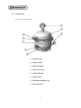
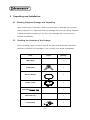
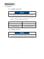
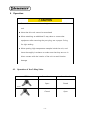
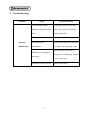
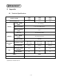
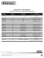
Operation Manual Round Vacuum Desiccators Models : F42400-2021, -2041, -2121, -2141, -2221, and -2241 Manual No. 942402021 Version 1.0 Table of Contents 1 Safety ......................................................................................................................................................................................1 2 1.1 Operation Manual ..........................................................................................................................................1 1.2 DANGER/CAUTION/NOTICE Alerts ........................................................................................................1 1.3 Danger Alerts ...................................................................................................................................................1 1.4 Caution Alerts ..................................................................................................................................................3 Product Description ......................................................................................................................................................4 2.1 Introduction .........................................................................................................................................................4 2.2 Characteristics .....................................................................................................................................................6 2.3 Components ........................................................................................................................................................9 3 Unpacking and Installation ................................................................................................................................... 10 3.1 Checking Shipment Damage and Unpacking ................................................................................. 10 3.2 Checking the Contents of the Package ............................................................................................. 10 3.3 Installation ....................................................................................................................................................... 11 4 3.3.1 Installation Environment.............................................................................................................. 11 3.3.2 Installation location ....................................................................................................................... 11 Operation ...................................................................................................................................................................... 12 4.1 Operation of the 3-way Valve ................................................................................................................ 12 4.2 Vacuum Formation ...................................................................................................................................... 14 5 Maintenance ................................................................................................................................................................ 16 6 Troubleshooting ......................................................................................................................................................... 17 7 Accessories ................................................................................................................................................................... 18 8 Appendix ....................................................................................................................................................................... 19 8.1 Technical Specifications ............................................................................................................................. 19 8.2 Disposal of the Unit .................................................................................................................................... 20 8.3 Warranty and Disclaimer .......................................................................................................................... 20 8.4 After-sales Service and Customer Assistance ................................................................................. 20 ii 1 Safety 1.1 Operation Manual This manual contains important safety and operation information. You must carefully read, understand, and follow all the instructions in this manual prior to operating this instrument. Keep this manual in a safe place nearby for reference and make it easily available to all users. 1.2 DANGER/CAUTION/NOTICE Alerts This manual highlights DANGER/CAUTION/NOTICE alerts to prevent injury or property damage and also to achieve optimum performance of your instrument. These alerts are classified into three types in this manual depending on the importance and the risk levels as described below: Symbols Meaning Ignoring this alert could cause serious or even fatal injury. Ignoring this alert could cause serious injury or property damage. Ignoring this alert could cause operational problems. Ensure to read the danger and caution alerts in 1.3 and 1.4 carefully before use. 1.3 Danger Alerts ◆ Never install or use this unit in explosive atmospheres. 1 ◆ Never install this unit near to hazardous or flammable substances. ◆ Never disassemble, repair, or modify this unit on your own. Doing so will void your warranty and may result in injuries or product damages. 2 1.4 Caution Alerts Ignoring the following cautions could cause serious injury or property damage. ◆ Carefully read all the warning labels before using this unit. And do not remove or damage the warning labels. ◆ Do not move this unit during operation. ◆ Do not use this unit in wet or moist atmosphere or where water leakage is expected. ◆ Do not use this unit in contaminated atmosphere or where metallic dust exists. ◆ Do not expose this unit to any heat sources including direct sunlight. ◆ Do not allow moisture, organic solvent, dust, or corrosive gases to get into this unit. ◆ Do not use chlorine bleach, ammonia-based cleaners, abrasives, ammonia, or metal scouring pads. Wipe with a soft damped cloth or a sponge soaked in water or diluted neutral detergent. 3 2 Product Description 2.1 Introduction Congratulations of your purchase of our high-quality round vacuum desiccator which is specially designed to provide maximum benefit for your investment with respect to performance, safety, ease of use, and durability. Currently six round vacuum desiccator models of are available from Bel-Art Products: F42400-2021, -2041, -2121, -2141, -2221, and -2241 All models come standard with a vacuum gauge while the models ending in xx41 are ambertinted and are UV blocking models. These UV blocking models are offered to minimize damages or discoloration of light-sensitive samples by using UV-blocking resin which completely blocks all ranges of UV and the blue spectrum of the visible light. Being lightweight and yet shatter-resistant, Bel-Art’s round vacuum desiccators are safer and more economical alternatives to conventional glass desiccators for both vacuum and nonvacuum applications. The vacuum environment created by these desiccators provides a very low humidity, contamination-free, corrosion-free, and dust-free condition which is ideal for: drying at low pressure to minimize the heat effects. removing residual solvents or air bubbles 4 cultivating anaerobic microbes minimizing the re-absorption of humidity and the exposure to air during the drying or the cooling stages of biological/medical/food/materials experiments conducting experiments at low pressure drying at low pressure to minimize the heat effects. 5 2.2 Characteristics (1) Outstanding Vacuum Sustainment This unit maintains a 1 Torr (133 Pa) vacuum for over 72 hours at room temperature and stays gastight allowing reliable experiments over extended periods. (2) Molded Polycarbonate Body and Base The body and the base of this unit are made of shock-resistant, highly tensile, and transparent polycarbonate to provide extreme durability as well as convenient visual observation from outside. The body is molded as a single piece requiring no adhesive and, therefore, allows virtually no leakage. (3) Viton® 3-Way Valve This unit comes standard with a leak-proof Viton® 3-way valve offering consistent and uniform vacuum draw, vacuum release, or gas exchange without the inconvenience of connecting and disconnecting pump hoses to the unit. If needed, an additional 3-way valve can be attached to the port at the base. (4) Locker 6 This unit is equipped with a locker which allows tight sealing for both vacuum and non-vacuum applications. In addition, this locker provides additional convenience and safety when moving the unit. (5) Wide Range of Models Currently six different models of are available: F42400-2021, -2041, -2121, -2141, 2221, and -2241 These models come in three different capacities to suit the user’s needs with the internal volume of 6, 10 or 20 liter . (6) Easy Vacuum Level Checking The vacuum gauge installed on top of the body allows convenient checking of the vacuum level. All models include a vacuum gauge. (7) UV Blocking These UV blocking models (F42400-2041, -2141, and -2241) are offered to minimize damages or discoloration of light-sensitive samples by using UV-blocking resin which completely blocks all ranges of UV and the blue spectrum of the visible light. (8) High Quality Vacuum Seal The silicone gasket ensures reliable vacuum formation and sustainment without using any grease. For easy cleaning and maintenance, the vacuum seal is specially designed 7 to fit snuggly into the bottom groove of the body. (9) Desiccant Tray All models come with a desiccant tray. Desiccants are sold separately. 8 2.3 Components Round Vacuum Desiccators ⑤ ④ ⑥ ③ ② ① ⑦ ⑧ (1) Desiccator jar (2) Flange Locker (3) Silicone Gasket (4) Desiccator cover (5) Vacuum Gauge (6) 3-Way Valve (7) Perforated Sample Tray (8) Desiccant Tray 9 3 Unpacking and Installation 3.1 Checking Shipment Damage and Unpacking Upon receiving the instrument, check to ensure that no damage has occurred during shipment. It is important that any damage that occurred during shipment is detected before unpacking. If you find such damage, the carrier must be notified immediately. 3.2 Checking the Contents of the Package After unpacking, check to ensure that all the parts and accessories described below are included in the package. If not, contact your dealer immediately. Item Figure Quantity Main Body - 1 3-Way Valve 1 Silicone Gasket 1 Flange Locker 1 Perforated Sample Tray - 1 Desiccant Tray - 1 User Manual 1 10 3.3 Installation 3.3.1 Installation Environment Avoid exposure to any heat sources including direct sunlight. This unit is designed for indoor use in laboratory environments. The conditions for proper installation are as follows: Permissible Ambient Temperature 5 to 40℃ (41 to 104°F) Permissible Relative Humidity Below 80% Permissible Altitude 0 to 2,000 m (6,562 ft) 3.3.2 Installation Location Install the unit on a level surface Install the unit at least 30cm away from other equipment 11 4 Operation Do not form a vacuum when airtight containers are inside the unit Note that this unit cannot be autoclaved When attaching an additional 3-way valve or some other equipment after removing the port plug, use a proper O-ring for tight sealing When putting high-temperature samples inside the unit, cool them thoroughly in advance or make sure that they are not in direct contact with the interior of the unit to avoid interior damage 4.1 Operation of the 3-Way Valve ITEM Front Nozzle Rear Nozzle Open Closed Closed Open Rear Front 12 Closed 13 Closed 4.2 Vacuum Formation The procedures for vacuum formation are as follows: (1) Connect the vacuum pump hose to one of the two nozzles of the 3-way valve (2) After activating the vacuum pump, turn the valve handle towards the nozzle to open it and read the vacuum gauge to check whether the vacuum is forming properly (3) When the desired vacuum level is achieved, turn the valve handle until it is perpendicular to the nozzle to close it and check the vacuum gauge whether there is any leakage (4) When releasing the vacuum, slowly turn the valve handle towards the opposite nozzle to return to the normal pressure .. 14 Do not impact or drop the unit when a vacuum is formed inside When forming or releasing a vacuum, turn the valve handle slowly to avoid rapid pressure change. If not, the stored samples can be damaged or dispersed When forming a vacuum, install a cold trap in front of the vacuum pump. Moisture and chemicals from the samples may result in damages to the pump. Do not let the body of the unit into direct contact with acetone, benzene, toluene, chloroform, cresol, sodium hydroxide, highly concentrated nitric or sulfuric acid, acetic acids, or strong chlorine-based solvents Ensure that the silicone gasket is not damaged by strong acid or base. Damaged gasket can cause malfunction of the unit When a vacuum is formed inside the unit, do not apply excessive force to the 3-way valves, the vacuum gauge, or any of their vicinities. Any damages caused by external forces can cause malfunction of the unit When the unit is not forming a vacuum, keep the valve handle perpendicular to the nozzles When relocating the unit, do not carry by the protruded parts such as the vacuum gauge or 3-way valves 15 5 Maintenance If the unit is contaminated, wear chemicals-resistant gloves before cleaning Regularly check the 3-way valves, the vacuum gauge, or any of their vicinities for any damage Regularly check the vacuum seal as well as the surface where the body and the base are in contact and keep them always clean and undamaged Make sure to clean the silicone gasket regularly using diluted neutral detergent. For thorough cleaning, detach the seal from the lid Do not use chlorine bleach, ammonia-based cleaners, abrasives, organic solvents, or metal scouring pads when cleaning. Use a soft cloth all the time. 16 6 Troubleshooting Problem Cause Corrective Action Contaminated surface Thoroughly clean the surface between the body and the with a soft cloth using diluted base neutral detergent Damaged gasket Replace the gasket Vacuum Unsuitable room Check the temperature whether Malfunction temperature it is within the operating range Check whether the valve is Misplaced or damaged 3properly set. If damaged, replace way valve it with a new one Damaged vacuum gauge 17 Replace the gauge 7 Accessories See enclosed addendum for Accessories Parts List 18 8 Appendix 8.1 Technical Specifications Models F42400Internal Volume (L) Gauge -2021 -2121 -2221 -2041 -2141 -2241 6 10 20 Range 0 ~ -0.1 (Analog) (MPa) Vacuum Max. Permissible 1.33 x 10⁻⁴ MPa (1Torr) Nozzle Diameter Ø 9.5 (mm) Cover/Jar Material Tray, PC (Polycarbonate) Flange PP (Polypropylene) Locker Vacuum Gasket Dimensions (mm) Overall(mm, WxH) Net weight(kg) Perforated Sample Tray(mm) Tray Max load(Kg) Silicone 286 x 279 353 x 325 427 x 399 (286 x 354) (353 x 400) (427 x 475) 1.5(1.7) 2.5(2.6) 4.2(4.3) 192 250 310 15 20 25 Color* Clear UV Protection (Range)* UV A,B,C 100% (200~450nm) *Note: Models F42400-2041, -2141, and 2241 are Amber color and have the UV blocking capabilities indicated above . 19 8.2 Disposal of the Unit Disposing of the unit must be done in an environmentally responsible way if it has been potentially exposed to bio-agents or radioactive samples. Failure to follow stringent requirements for appropriate disposal may lead to actions against you and your organization. (1) First, check with your laboratory or organization to ensure that you are following all the policies and procedures for disposal of laboratory equipments and wastes. (2) If not possible, contact your local governing body for regulations regarding disposal of laboratory equipments. Jeio Tech highly recommends you to find a local service provider that can properly dispose of your unit. 8.3 Warranty and Disclaimer See enclosed Warranty Card for conditions and requirements. 8.4 After-sales Service and Customer Assistance Our after-sales service responds to your questions concerning maintenance and repair of your unit as well as spare parts. In case of a warranty claim, repair or purchase of replacement parts or in case of queries or other problems, please contact your local dealer or Bel-Art Products representative. 20 The contents of this manual can be changed or upgraded without prior notice. The copyright of this manual is reserved by Bel-Art Products. 21 Addendum to User Manual Accessories Parts List for Round Model Desiccators Bel-Art Accessory No. Unit of Measure Accessory Description Used with Bel-Art Desiccator Number(s) 942402035 EA Vacuum Gauge F42400-2021, -2041, -2121, -2141, -2221, -2241 942402034 EA Seal F42400-2021, -2041 942402033 EA Seal F42400-2121, -2141 942402032 EA Seal F42400-2221, -2241 942402031 EA Desiccant Tray F42400-2021, -2041 942402030 EA Desiccant Tray F42400-2121, -2141 942402029 EA Desiccant Tray F42400-2221, -2241 942402028 EA Perforated Shelves F42400-2021, -2041 942402027 EA Perforated Shelves F42400-2121, -2141 942402026 EA Perforated Shelves F42400-2221, -2241 942402025 EA Flange Locker F42400-2021, -2041 942402024 EA Flange Locker F42400-2121, -2141 942402023 EA Flange Locker F42400-2221, -2241 942402022 EA 3-Way Valve (For Round) F42400-2021, -2041, -2121, -2141, -2221, -2241 942402021 EA User Manual - Round Models F42400-2021, -2041, -2121, -2141, -2221, -2241 661 Route 23 South, Wayne, NJ 07470 TEL: 1-800-4BEL-ART • FAX: 973-694-7199 • www.belart.com Scienceware® is a registered TM of Bel-Art Products. Bel-Art Products assumes no obligation or liability for any advice furnished by it, or for results obtained with respect to these products. All such advice is given and accepted at the buyer’s risk. © 2012 Bel-Art Products. All Rights Reserved. 10/12


![Intra-Pod instructions.ppt [Read-Only]](http://vs1.manualzilla.com/store/data/007247390_1-f78b03339eb740c14aa24b2c59786747-150x150.png)