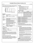
1
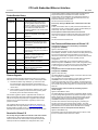
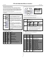
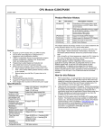
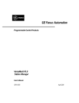
CPU with Embedded Ethernet Interface
June 2010
GFK-1892J
IC200CPUE05 shares the basic features of the other VersaMax PLC
CPUs. It provides powerful PLC functionality in a small, versatile
system. CPUE05 can serve as the system controller for up to 64
modules with up to 2048 I/O points. Two serial ports provide RS-232
and RS-485 interfaces for serial communications. CPUE05 also
provides a built-in Ethernet Interface. The RS-232 serial port can be
configured for Local Station manager operation to provide access to
diagnostic information about the Ethernet interface. CPUE05 has 128kB
of configurable memory.
Specifications
Size
Program storage
In addition, CPUE05 is compatible with the EZ Program Store device,
which can be used to write, read, update, and verify programs,
configuration, and reference table data without a programmer or
programming software.
CPUE05
PWR
Power Supply current consumption
with no serial port converter or EZ
Program Store device
5V uses 220mA
Power Supply current consumption
with serial port converter or EZ
Program Store device
5V uses: 320mA
Floating point
Boolean execution speed
Real time clock accuracy (for timer
functions)
Time of day clock accuracy
MAC XXXXXXXXXXXX
OK
RUN
FAULT
FORCE
PORT 1
Width: 4.95” (126mm) - along DIN rail
Length: 5.04” (128mm)
Depth: 2.72” (69.1mm)
System flash, battery-backed RAM
IC200CPUE05
PORT 2
PORT 1
Embedded communications
Configurable memory
Ethernet Interface Specifications
Ethernet data rate
Ethernet port
Number of SRTP server
connections
Number of Ethernet Global Data
(EGD) configuration-based
exchanges
EGD Exchange limits
IP ADDRESS
RS232
PORT 2
ETHERNET
RESTART
ETHERNET
10 MBPS BASE T
LAN
STAT
PORT 1
RS485
Features
▪
▪
▪
▪
▪
▪
▪
▪
▪
▪
▪
EGD Time Synchronization
EGD Selective Consumption
Load EGD configuration from PLC
to programmer
Remote Station Manager over UDP
Local Station Manager
(RS-232)
Supports up to 64 modules with up to 2048 I/O points
Can be either autoconfigured or configured from a programmer
using configuration software
128KB of configurable memory for the application program,
hardware configuration, registers (%R), analog inputs (%AI),
and analog outputs (%AQ)
Programming in Ladder Diagram and Instruction List
Non-volatile flash memory for program storage
Battery backup for program, data, and time of day clock
Super capacitor provides power to memory for 1 hour
Over 1 hour, backup battery protects memory contents up
to 6 months.
Backup battery has shelf life of 5 years when not in use.
Run/Stop switch
Floating point (real) data functions
Embedded RS-232, RS-485, and Ethernet communications
70mm height when mounted on DIN rail with power supply
(sold separately)
3.3V uses: 570mA
Yes
0.8 ms/K (typical)
100ppm (0.01%) or +/- 9sec/day
23ppm (0.0023%) or +/- 2sec/day @ 30C.
100ppm (0.01%) or +/- 9sec/day @ full
temperature range
RS-232, RS-485, Ethernet
128K bytes maximum
10Mbps (half- or full-duplex)
RJ-45, UTP
8
32
100 data ranges per exchange
1400 bytes of data per exchange
NTP
Yes
Yes
Yes
Via CPU Port 1
Product Information
▪
▪
Revisions:
CPUE05-DH, CPUE05-EH
Power Supply
Requires PWRx02
Firmware:
Version 2.36
Programmer
Compatibility:
VersaPro software version 2.0 or later, and
Machine Edition Logic Developer.
All types of I/O and communications modules
can be used in expansion racks. Some analog
modules require specific module revisions in
expansion racks, as listed below:
Module
Module Revision
*ALG320
B or later
*ALG321
B or later
*ALG322
B or later
*ALG430
C or later
*ALG431
C or later
*ALG432
B or later
Expansion I/O
Compatibility:
1
CPU with Embedded Ethernet Interface
June 2010
GFK-1892J
communication between master and slave failed, the slave did not
respond to subsequent commands from master, even after
communication was re-established. This happened irrespective of
master PLC/CPU type. A power cycle of the slave Micro PLC was
required to restore the communication.
Product Revision History
Rev
Date
Description/Features
CPUE05-EH
CPUE05-DH
June 2010
Firmware release 2.36
Modbus Serial Communication issues
when using Radio modems have been
corrected. In addition, prior to release 2.36
the PLC incorrectly accepted invalid values
for the TOD clock. Please refer to the
“Resolved for Release 2.36” section below
for more details.
CPUE05-EG
March 2010
This issue is resolved in release 2.36.
Port Lock up during the Modbus RTU communication with radio
modems
In RTU communication when any delay was introduced between two
characters of a frame, causing a break in frame, the RTU Master port
would lockup. This issue is resolved in release 2.36.
PLC accepted an invalid month value for the TOC clock
Changed manufacturing location. No
changes to compatibility, functionality or
performance.
The PLC would accept an invalid month value input for Time of Day
clock which resulted with a Controller CPU Hardware failure” error
message.
CPUE05-DG October 2008 Updated Power Supply OK signal circuit.
This issue is resolved in release 2.36.
CPUE05-CG January 2006 Firmware release 2.35
Corrections to PID function block, serial
communications, and EZ Program Store
device features.
CPUE05-CF
CPUE05-BE
June 2004
June 2003
New Features and Enhancements in Release 2.36
Configuration for Receive to Transmit Delay in RTU Master
Configuration COMMREQ
Firmware release 2.34
Serial communications and PID function
block enhanced. Changed to V0 plastic for
module housing.
Applies to RTU Master Only
This configuration provides an option for the user to select ‘Receive to
Transmit Delay’ for Master. The device will force this delay after the last
byte is received and the last frame transmitted out of current port.
ATEX approval for Group 2, Category 3
applications. Firmware release 2.32
Support for 32-bit register data for
Modbus® RTU Master
‘Receive to Transmit Delay’ configuration is not linked to End of Frame
timeout. User has to take care of inter operability of these
configurations.
CPUE05-AD
March 2003
Firmware release 2.31
Support for Modbus RTU Master
CPUE05-AC
not released Firmware release 2.30
CPUE05-AB
March 2002
Firmware release 2.20
Added new serial I/O baud rates
‘Receive to Transmit Delay’ can be configured at Word 23 of RTU
Master Configuration COMMREQ. This is an 8-bit configuration having
10 millisecond units. The value range is 0 to 255. The default value is
0, which configures this delay as 3.5 character times at current
baud rate.
CPUE05-AA
March 2001
Firmware release 2.10
Initial Product Release
Configuration for End of Frame timeout in RTU Slave
Configuration COMMREQ
Applies to RTU Slave Only
Firmware Upgrades
This feature allows the user to configure ‘end of frame’ timeout in RTU
Slave configuration COMMREQ.
Firmware release 2.36 replaces all previous versions. If you need to
determine the current firmware version of a CPU, see the steps below:
This configuration can be set at Word 19 of RTU Slave Configuration
COMMREQ. This is a 16-bit configuration with units of 100
microseconds and Value range from 0 to 65535. The default value is 0,
which configures this delay as 3.5 character times at current baud rate.
The minimum value for this configuration is 3 character times at current
baud rate.
▪
▪
With Machine Edition Logic Developer, go online to the CPU,
then select Target > Online Commands > Show Status. The
Device Information Software Revision shows the current firmware
revision level.
With a VersaPro or Control programmer, attach the CPU. Under
the PLC menu (VersaPro) or the Comm menu (Control), select
the Memory tab on the Status Information dialog.
Smart recognition of End of Frame by calculating expected
number of bytes
Applies to RTU Master & Slave
This feature allows the device operating as either RTU Master or Slave,
to ignore garbage data appended to any valid RTU message. The RTU
Master compares the received bytes with expected number of bytes.
The expected number of bytes in the Master is calculated while the
COMMREQ information is processed to create the query.
This firmware upgrade is optional. Applications that use RTU and
SNPX communication with radio modems and applications that use
TOD service request may benefit from an upgrade to CPU firmware
version 2.36. For all other applications, upgrading to version 2.36
provides no benefit.
The RTU Slave determines the message length by examining the
Function code in the query message during reception. The slave
determines the expected query message length after receiving at least
two characters and no more than seven characters of the message.
The upgrade kit 4A751470-G07 can be ordered from the factory, or
downloaded from the Support website, www.ge-ip.com/support. The
firmware resides in FLASH memory, and is upgraded by serial
download from a Windows PC via CPU port 1. Port 2 cannot be used.
Different Error Code for Incomplete Frame & CRC Error
Applies to RTU Master Only
If the Master receives the incomplete frame and if the CRC is invalid,
the error code 0607H will be returned as a status.
Resolved for Release 2.36
Port Lockup during the SNPX communication with radio modems
In SNPX protocol, while communicating through modems (dial-up
modems, switched carrier radio modems and packet oriented radio
modems) and with the VersaMax PLC configured as slave, if the
2
CPU with Embedded Ethernet Interface
June 2010
GFK-1892J
configuration is stored. If the Target/Download and Start option
of Machine Edition Logic Developer – PLC is used to store the
modified EGD configuration, production of EGD exchanges may
not begin as expected.
Restrictions/ Operating Notes
1.
When a serial port is configured for either Modbus RTU (slave or
master) or Serial I/O, and a parity, framing or over-run error occurs
while a serial message is being received, the next message
received is ignored.
2.
When a serial port is configured for Modbus RTU slave, an SNP
master device (for example, a serial programmer or HMI/SCADA
device that uses the SNP protocol) may attach to the port. If the
SNP device is disconnected and then an RTU query is sent to the
port before 10 seconds have elapsed, the port is unable to receive
any serial messages. To recover, power to the CPU must be
turned off and then on.
3.
When a serial port is configured for Serial I/O, and a new hardware
configuration is stored that changes the port protocol to SNP, the
port may not respond to SNP Attach messages until the CPU is
powered off and then on.
4.
Using an older revision non-intelligent analog module in an
expansion rack will cause a System Configuration Mismatch error
to be logged. The faulted module must be replaced with a newer
revision before it will be scanned. The allowed revisions are
detailed under Compatibility, in the Product Information section,
above.
To avoid this issue, always store the hardware configuration using
the Target/Download option, wait 5 seconds, and then transition
manually to RUN Mode.
13. Changing an IND or ISA PID function block integral rate
parameter value from 1 (that is, from 0.001 repeats/sec.) to 0 or
from 0 to 1 causes a step change in both the integral term and the
control variable (CV) output. This result is expected. A zero
integral rate value specifies that the integral term contribution to
CV is zero, while a non-zero value specifies a non-zero
contribution.
14. In rare instances, exceptions 28/1e and/or 1/0e may occur during
power down of the CPUE05. These do not indicate a problem and
may be ignored.
15. In very rare instances, the CPU may not add a module being hot
inserted. It will not generate an ‘Addition of Module’ fault and the
module will not be scanned. The situation can be corrected by
extracting and re-inserting the module.
16. In very rare instances, a module being hot inserted may cause
analog modules in the same rack to set outputs to zero. In
addition, ‘Loss of Module’, ‘System Configuration Mismatch’ or
field faults may be generated on other modules in the same rack.
If the modules do not return to correct behavior momentarily,
power cycling will restore full operation.
5.
Occasionally, a "Backplane Communication Fault" may be logged
on an intelligent I/O module after power-cycling the main or
expansion rack. This is a diagnostic fault that can be cleared.
6.
If the receiver in a local single rack is powered off while the CPU is
powered on, erroneous “Addition of rack” faults may be logged by
the CPU. It is recommended that both the CPU and the receiver
be powered by a single source.
7.
In very rare instances, when field power is lost on one module,
non-intelligent modules in the same rack may also report faults.
8.
In series 90-30 CPUs, the Shift Register Bit (SHIFR_BIT)
instruction may be used to rotate a bit sequence around a range of
discrete references by specifying the same reference for the
output, Q, and the start reference, ST.
18. If the PLC Fault Table is cleared, but the I/O Fault Table is not,
the Ethernet interface may not regenerate pre-existing faults.
Conversely, if the I/O Fault Table is cleared, and the PLC Fault
Table is not, faults may be duplicated in the PLC Fault Table. It is
recommended that you clear the PLC and I/O Fault Tables at the
same time.
However, in VersaMax CPUs, separate references must be used
for ST and Q, and additional logic must be used to copy the output
bit from the Q reference to the ST reference.
19. The CPUE05 gives priority to servicing the user logic program
before servicing Ethernet traffic. Therefore, a long sweep time
may impact Ethernet throughput.
When the configured size of a reference table is changed after the
table is stored to flash memory, and the user attempts to read
Initial/Forced Values from flash memory, the table will be filled with
zeros.
20. When servicing Ethernet traffic, the CPUE05 gives priority to
servicing EGD traffic before servicing SRTP traffic, and gives
priority to servicing SRTP traffic before servicing Station Manager
traffic. Therefore, a heavy load of EGD traffic can lock out SRTP
operation and likewise a heavy load of EGD and/or SRTP traffic
can lock out Station Manager operation. For example,
configuring the CPUE05 with 32 EGD exchanges at rates faster
than 150 ms will result in frequent timeouts on SRTP operations.
9.
17. When using the VersaPro programmer connected to the CPUE05
via Ethernet, exceptions 8/8 and 8/16 may occur when frequently
changing reference view tables to a PLC with a very long (> 300
ms) sweep time.
10. In release 2.36, new COMMREQ parameters are added for RTU
Port Setup COMMREQ. The RTU Master Port Setup COMMREQ
has a new configuration word for Receive to Transmit Delay along
with Character Gap Timeout. The RTU Slave Port Setup
COMMREQ has a new configuration word for Character Gap
Timeout along with Receive to Transmit Delay.
21. Do not issue multiple “ping” requests to a CPUE05 – it processes
one incoming ping at a time.
These parameters are not inter-dependent and are configured and
used independently.
22. If the configured data length of a consumed EGD exchange does
not match the received data length, the PLC Fault Table will be
filled with entries (exception 28/1d) until the condition is corrected.
Use the Station Manager “Stat g” command to determine which
exchange is misconfigured.
11. When downloading a hardware configuration through the Ethernet
port, do not check the Write all items to flash option of the
Store/Download dialog. Checking that option causes the download
to fails and disconnects the programmer. The Ethernet interface
switches to its backup configuration and posts a PLC fault
indicating that a time-out expired while waiting for a hardware
configuration. The interface must be restarted to restore Ethernet
communications.
23. Caution to NTP users:
a) No exception reported if NTP server not available at startup.
b) Station Manager startup message does not display correct
time if NTP configured.
c) Do not set NTP advanced user parameters nminpoll* and
nmaxpoll* to the same value.
d) Do not use more than one NTP server of the same stratum.
e) Do not specify the IP address of a CPUE05 as the time server
in the configuration of a CPUE05 or other device.
The flash write option only succeeds when used with stores of
logic and/or reference table values.
12. When a hardware configuration that contains an Ethernet Global
Data (EGD) exchange was previously stored to a CPUE05, and
the definition of the EGD exchange is modified without changing
the exchange ID, the CPU’s Ethernet interface requires a few
seconds to process the new definition when the hardware
3
CPU with Embedded Ethernet Interface
June 2010
GFK-1892J
24. If your application attempts to perform more Ethernet
communication than the CPUE05 can support, the following
behaviors may be observed:
Changes to the User’s Manual
The following changes apply to the ModBus RTU Master
Communications datasheet, GFK-2220C.
a)
The Ethernet interface may restart itself and the exception log
will contain 28/1 exceptions followed by a system error restart
1/5.
b) Ethernet operation will stop and the Ethernet LEDs in the
lower right corner will blink indicating fatal fault 31. Push the
Ethernet restart pushbutton to recover normal Ethernet
operation.
c) Ethernet operation will stop, the Ethernet LAN LED will go off,
and pushing the Ethernet restart pushbutton will have no
effect. There will be no response to Station Manager
commands. Ten seconds later, the Ethernet interface will
restart itself. The exception log will contain a restart due to
watchdog timeout 1/0c.
d) The application may fail to receive data from one or more
nodes that are transmitting data to it. Push the Ethernet
restart pushbutton to recover normal Ethernet operation.
e) The exception log will contain 28/1b and/or 28/1d exceptions.
For each such exception, data for one EGD consumption
sample will not be delivered into reference memory
NOTE: If your application experiences these symptoms of
overload, you must reduce the number/frequency/size of EGD
exchanges and/or number/frequency/size of SRTP channels.
1.
Major Error Code: RESPONSE_ERROR
Numeric
Status
Value
Minor error code
Description
INCOMPLETE_FRAME_
INVALID_CRC
0607H
The response received is an
incomplete frame and CRC is
invalid.
INCOMPLETE_FRAME_
VALID_CRC
0207H
The response received is an
incomplete frame and CRC is valid.
COMPLETE_FRAME_
INVALID_CRC
0107H
The response received is a
complete frame but CRC not
matched.
2.
25. EGD group number to UDP port number assignment cannot be
changed by setting the g*_udp advanced user parameters.
In the section “ModBus RTU Master Commands” new parameters
are added for the command “Initialize RTU Master Port: 65520
(FFF0)”. The details are as follows.
RTU Mode: RTU Master
26. The CPUE05 does not support “supernetting”, a technique of
configuring the subnet mask in such a way to allow communication
to multiple subnets.
Location
Address+22
27. Sustained heavy SRTP Server operation with very large data
transfers (>32Kbytes) can cause loss of an internal resource called
message buffers. This can result in reduced network performance
and possible loss of message received from the network.
28. The CPUE05 does not reject a configuration containing a
broadcast or multicast value for the module’s IP Address. Do not
configure broadcast or multicast values for an individual IP
address. Avoid addresses of the following forms:
▪
▪
▪
▪
In the section “Error Codes for RTU Master Commands,” the
following error code needs to be added.
Value
0-255 (units of
10ms,e.g.
10=100ms)
Description
Receive to Transmit Delay
Note: This is an independent delay
between the latest character received and
the first character sent. There is no
interoperability between the Character
Gap Timeout and this value.
RTU Mode: RTU Slave
Location
x.y.z.255
Address+19
>223.x.y.z
x.y.z.0
x.y.z.1
Such addresses may result in erratic communications behavior.
Value
0 – 65,535 (0 to
6.5535
seconds)
0 = Default
29. When a CPUE05 is configured as RTU Master and Receive to
Transmit delay is configured for other than minimum value, if noise
or garbage data is received during RTU communication, while
CPU waits for Receive to Transmit delay to expire, a correct
response may get reported as an error response in COMMREQ
status word.
Description
Character Gap Timeout in
100-microsecond increments.
Note: Specifies the time that the
Master/Slave waits after receiving a broken
frame before setting end of frame. This is
an individual parameter that doesn’t have
any relationship with other parameters.
Note: After configuring the Receive to Transmit and Character Gap
Delays, you must synchronize Master and Slave for successful
communication.
4
CPU with Embedded Ethernet Interface
June 2010
GFK-1892J
Panel-Mounting
Preinstallation Check
If excessive vibration is a factor the CPU should also be screwed down
to the mounting panel.
Carefully inspect all shipping containers for damage. If any equipment is
damaged, notify the delivery service immediately. Save the damaged
shipping container for inspection by the delivery service. After
unpacking the equipment, record all serial numbers. Save the shipping
containers and packing material in case it is necessary to transport or
ship any part of the system.
Note 1. Tolerances are +/- 0.13mm (0.005in) non-cumulative.
Note 2. 1.1-1.4Nm (10-12 in/lbs) of torque should be applied to M3.5
(#6-32) steel screw threaded into material containing internal
threads and having a minimum thickness of 2.4mm (0.093in).
SEE NOTE 2.
Installation in Hazardous Locations
•
•
4.3mm
0.170in
EQUIPMENT LABELED WITH REFERENCE TO CLASS I, DIV. 2,
GROUPS A, B, C & D, HAZARDOUS LOCATIONS IS SUITABLE
FOR USE IN CLASS I, DIVISION 2, GROUPS A, B, C, D OR
NON-HAZARDOUS LOCATIONS ONLY
FLAT WASHER
4.3mm
0.170in
WARNING - EXPLOSION HAZARD - SUBSTITUTION OF
COMPONENTS MAY IMPAIR SUITABILITY FOR CLASS I,
DIVISION 2;
•
WARNING - EXPLOSION HAZARD - WHEN IN HAZARDOUS
LOCATIONS, TURN OFF POWER BEFORE REPLACING OR
WIRING MODULES; AND
•
WARNING - EXPLOSION HAZARD - DO NOT DISCONNECT
EQUIPMENT UNLESS POWER HAS BEEN SWITCHED OFF OR
THE AREA IS KNOWN TO BE NONHAZARDOUS.
M3.5 (#6) SCREW
SPLIT LOCK
WASHER
5.1mm
0.200in
15.9mm
0.62in REF
TAPPED
HOLE IN
PANEL
CPU
Removing the CPU from the DIN Rail
1.
2.
Module Installation
3.
This equipment may be mounted on a horizontal or vertical DIN rail. If
mounted on a vertical DIN rail, the CPU module must be located at the
bottom. The CPU and connecting carriers must be installed on the
same section of 35mm x 7.5mm DIN rail, 1mm thick. Steel DIN rail is
recommended. The DIN rail must be electrically grounded to provide
EMC protection. The rail must have a conductive (unpainted) corrosionresistant finish. DIN rails compliant with DIN EN50022 are preferred.
For vibration resistance, the DIN rail should be installed on a panel
using screws spaced approximately 15.24cm (6 inches) apart.
4.
Turn off power to the power supply.
(If the CPU is attached to the panel with a screw) remove the
power supply module. Remove the panel-mount screw.
Slide the CPU away from the other modules until the connector on
the right side disengages from the next carrier.
With a small flathead screwdriver, pull the DIN rail latch outward
while tilting the other end of the module down to disengage it from
the DIN rail.
Activating or Replacing the Backup Battery
The CPU is shipped with a battery already installed. The battery holder
is located in the top side of the CPU module. Before the first use,
activate the battery by pulling and removing the insulator tab.
Rated thermal specifications for the CPU module are based on a
clearance of 2” above and below the equipment and 1” to the left of the
CPU module.
1.
Allow sufficient finger clearance for opening CPU door.
2.
Allow adequate clearance for serial port and Ethernet cables.
3.
Allow adequate space for power wiring.
To replace the battery, use a small screwdriver to gently pry open the
battery holder. Replace battery only with*ACC001 from your PLC
supplier, or with Panasonic battery: BR2032. Use of another battery
may present a risk of fire or explosion.
The CPU with power supply attached fits into a 70mm deep enclosure.
Installing the CPU on the DIN Rail
Caution
The CPU snaps easily onto the DIN rail. No tools are required for
mounting or grounding to the DIN rail.
Battery may explode if mistreated.
Do not recharge, disassemble, heat above 100 °C (212 °F) or
incinerate.
Before joining module carriers to the CPU, remove the connector cover
on the right-hand side of the CPU. Do not discard this cover, you will
need to install it on the last carrier, to protect the connector pins from
contamination and damage during use.
5
CPU with Embedded Ethernet Interface
June 2010
GFK-1892J
Switching the PLC Operating Mode
Observing the Module LEDs
The CPU contains two sets of LEDs, one in the upper left corner and
one in the lower right corner.
The CPU Run/Stop mode switch is located behind the module door.
This switch can be used to place the CPU in Stop or Run mode. It can
also be used to block accidental writing to CPU memory and forcing or
overriding discrete data. Use of this feature is configurable. The default
configuration enables Run/Stop mode selection and disables memory
protection.
PWR
OK
RUN
The LEDs in the upper left corner indicate the presence of
power and show the operating mode and status of the
CPU.
FAULT
FORCE
PORT 1
RUN/ON
PORT 2
STOP/OFF
FORCE
ON when the CPU is receiving 5V power from the power supply.
Does not indicate the status of the 3.3V power output.
ON indicates the CPU has passed its powerup diagnostics and is
functioning properly. OFF indicates a CPU problem. Fast blinking
indicates that the CPU is running its powerup diagnostics. Slow
blinking indicates the CPU is configuring I/O modules.
(Simultaneous blinking of this LED and the green Run LED indicates
that the CPU is in boot mode and is waiting for a firmware update
through Port 1.)
Green when the CPU is in Run mode. Amber when the CPU is in
Stop/IO Scan mode. If this LED is OFF but OK is ON, the CPU is in
Stop/No IO Scan mode. If this LED is flashing green and the Fault
LED is ON, the module switch was moved from Stop to Run mode
while a fatal fault existed. Toggling the switch will continue to Run
mode.
ON if the CPU is in Stop/Faulted mode because a fatal fault has
occurred. To turn off the Fault LED, clear both the I/O Fault Table
and the PLC Fault Table. If this LED is blinking and the OK LED is
OFF a fatal fault was detected during PLC powerup diagnostics.
Contact PLC Field Service.
ON if an override is active on a bit reference.
PORT 1
PORT 2
Blinking indicates activity on that port. (Note: does not blink to
indicate local Station Manager activity, see PORT 1 LED below.)
POWER
If Run/Stop mode switch operation is enabled, the switch can be used
to place the CPU in Run mode.
OK
If the CPU has non-fatal faults and is not in Stop/Fault mode, placing
the switch in Run position causes the CPU to go to Run mode. Faults
are NOT cleared.
If the CPU has fatal faults and is in Stop/Fault mode, placing the switch
in Run position causes the Run LED to blink for 5 seconds. While the
Run LED is blinking, the CPU switch can be used to clear the fault table
and put the CPU in Run mode. After the switch has been in Run
position for at least ½ second, move it to Stop position for at least ½
second. Then move it back to Run position. The faults are cleared and
the CPU goes to Run mode. The LED stops blinking and stays on. This
can be repeated if necessary.
RUN
If the switch is not toggled, after 5 seconds the Run LED goes off and
the CPU remains in Stop/Fault mode. Faults stay in the fault table.
FAULT
Ethernet Restart Pushbutton
The Ethernet Restart pushbutton is located on the right side of the
module.
LAN
Ethernet Restart
Pushbutton
ETHERNET
RESTART
STAT
PORT 1
ETHERNET
10 MBPS BASE T
LAN
STAT
PORT 1
LAN
The Ethernet Restart pushbutton has two functions:
▪
▪
When pressed for less than 5 seconds, it resets the Ethernet
hardware, tests the Ethernet LEDs, and restarts the Ethernet
firmware. This disrupts any Ethernet communications that are
presently underway.
When pressed for at least 5 seconds, it toggles the function of
Port 1 between its configured operation and forced local
Station Manager operation.
STAT
PORT 1
6
The LEDs in the lower right corner show the operating
mode and status of the Ethernet port. The Ethernet
LEDs turn ON briefly, first amber then green, whenever
a restart is performed in the Operational state by
pressing and releasing the Restart pushbutton (see
below). This allows you to verify that the Ethernet
LEDs are operational. All three LEDs blink green in
unison when a software load is in progress.
Indicates the status and activity of the Ethernet network connection.
ON/flickering green indicates Ethernet interface is online. ON amber
indicates Ethernet interface is offline.
Indicates the general status of the Ethernet interface. ON green
indicates no “exception” detected. ON amber indicates an exception.
Blinking amber indicates error code. Blinking green indicates waiting
for configuration or waiting for IP address.
ON amber indicates Port 1 is available for local Station Manager use
(either by configuration or forced). OFF indicates PLC CPU is
controlling Port 1.
CPU with Embedded Ethernet Interface
June 2010
GFK-1892J
Cable Diagram for Attachment to a PC
Using the CPU Serial Ports
The CPU’s two serial ports are software-configurable for SNP slave,
RTU slave, Serial I/O operation, or local Station Manager operation
(Port 1 only). If a port is being used for RTU, it automatically switches to
SNP slave mode if necessary. Both ports’ default configuration is SNP
slave mode. If configured for Serial I/O, a port automatically reverts to
SNP slave when the CPU is in Stop mode.
5
RS232
PORT 2
9
RS485
6
7
3
3
4
4
5
5
8
9
CPU
Port 1
9-pin male
(2) TXD
(3) RXD
(5) GND
(7) CTS
(8) RTS
The shield must attach to shell of
connectors on both ends of the cable.
Vendor Part numbers below are provided for reference only. Any part
that meets the same specification can be used.
Cable:
Belden
9610
Computer cable, overall braid over foil shield
5 conductor †
30 Volt / 80°C (176°F)
24 AWG tinned copper, 7x32 stranding
Vendor:
Plug:
Type:
Pin:
ITT/Cannon
Crimp
DEA9PK87F0
030-2487-017
AMP
205204-1
66506-9
9 Pin Male
Connector
:
Solder
Connector
Shell:
Pin Assignments for Port 1
Direction
PC 9-Pin
Serial Port
9-pin female
(2) RXD
(3) TXD
(5) GND
(7) RTS
(8) CTS
Connector and Cable Specifications for Port 1
Port 2 is an RS-485 port with a 15-pin female D-sub
connector. This can be attached directly to an RS-485 to
RS-232 adapter (IC690ACC901). Port 2 can be used for
program, configuration, and table updates with the EZ
Program Store module. Port 2 screw locks are threaded
(metric) M3x0.5).
8
2
8
If Port 1 is configured as a local Station Manager, it
cannot be used for CPU serial communications and the
Ethernet Restart pushbutton will NOT toggle it to the
CPU serial protocols.
1
2
7
Port 1 is an RS-232 port with a 9-pin female D-sub
connector. The pinout of Port 1 allows a simple, straightthrough cable to connect with a standard AT-style RS232 port. Cable shielding attaches to the shell. Port 1
screw locks are threaded #4-40. Port 1 can be
configured for either CPU serial communications (SNP,
RTU, Serial I/O), or local Station Manager use. If Port 1
has been configured for CPU use, it can be forced to
local Station Manager operation using the Ethernet
Restart pushbutton. Port 1 remains in that mode until the
PLC is power cycled, or the Ethernet Restart pushbutton
is pressed.
1
1
6
An external device can obtain power from Port 2 if it requires 100mA or
less at 5VDC.
PORT 1
1
†
Function
ITT/Cannon
AMP
ZDE9P
747904-2
---
Kit* – ITT Cannon DE121073-54 [9-pin size backshell kit]:
Metal-Plated Plastic (Plastic with Nickel over Copper) †
Cable Grounding Clamp (included)
40° cable exit design to maintain low-profile installation
Plus – ITT Cannon 250-8501-010 [Extended Jackscrew]:
Threaded with #4-40 for secure attachment to port †
Order Qty 2 for each cable shell ordered
Critical Information – any other part selected should meet or exceed this
criteria.
Use of this kit maintains the 70mm installed depth.
Pin
Signal
1
n/c
2
TXD
Output
Transmit Data output
3
RXD
Input
Receive Data input
Pin
Signal
Direction
Function
--
1
SHLD
--
Cable Shield Drain wire connection
0V/GND signal reference
2, 3, 4
n/c
--
5
P5V
Output
+5.1VDC to power external level
converters (100mA max.)
6
RTSA
Output
Request to Send (A) output
7
GND
--
0V/GND reference signal
8
CTSB’
Input
Clear to Send (B’) input
9
RT
--
Resistor Termination (120 ohm) for RDA’
10
RDA’
Input
Receive Data (A’) input
11
RDB’
Input
Receive Data (B’) input
12
SDA
Output
Transmit Data (A) output
13
SDB
Output
Transmit Data (B) output
14
RTSB
Output
Request to Send (B) output
15
CTSA’
Input
Clear to Send (A’) input
Shell
SHLD
--
Cable Shield wire connection / 100%
(Continuous) shielding cable shield
connection
*
--
4
n/c
5
GND
6
n/c
7
CTS
Input
Clear to Send input
8
RTS
Output
Request to Send output
9
n/c
Shell
SHLD
--
Pin Assignments for Port 2
---
Cable Shield wire connection / 100%
(Continuous) shielding cable shield connection
7
--
CPU with Embedded Ethernet Interface
June 2010
GFK-1892J
The Ethernet interface can be used to:
Connector and Cable Specifications for Port 2
▪
Vendor Part numbers below are provided for reference only. Any part
that meets the same specification can be used.
Cable:
Belden
8105
15 Pin Male
Connector:
Connector
Shell:
Low Capacitance Computer cable, overall braid over foil shield
5 Twisted-pairs †
Shield Drain Wire †
30 Volt / 80°C (176°F)
24 AWG tinned copper, 7x32 stranding
Velocity of Propagation = 78%
Nominal Impedance = 100Ω †
Type:
Vendor:
Plug:
Pin:
Crimp
ITT/Cannon
DAA15PK87F0
030-2487-017
AMP
205206-1
66506-9
Solder
ITT/Cannon
ZDA15P
-AMP
747908-2
--
▪
▪
Kit*– ITT Cannon DA121073-50 [15-pin size backshell kit]:
Metal-Plated Plastic (Plastic with Nickel over Copper) †
Cable Grounding Clamp (included)
40° cable exit design to maintain low-profile installation
Plus – ITT Cannon 250-8501-009 [Extended Jackscrew]:
Threaded with (metric) M3x0.5 for secure attachment †
Order Qty 2 for each cable shell ordered
▪
▪
† Critical Information – any other part selected should meet or exceed this
criteria.
*
Use of this kit maintains the 70mm installed depth.
Cable Lengths
Maximum cable lengths the total number of feet from the CPU to the
last device attached to the cable are:
Ethernet LAN Port
The 10BaseT twisted pair cable must meet applicable IEEE 802
standards. Category 5 is recommended.
Port 1 (RS-232) = 15 meters (50 ft.)
Port 2 (RS-485) = 1200 meters (4000 ft.)
Ethernet
LAN Port
10BaseT
RJ-45
Serial Port Baud Rates
Port 1
RTU protocol
1200, 2400, 4800, 9600,
19.2K, 38.4*K, 57.6*K
Serial I/O protocol
1200, 2400, 4800, 9600,
19.2K, 38.4K*, 57.6K*
1200, 2400, 4800, 9600,
19.2K, 38.4K*, 57.6K*
SNP protocol
4800, 9600, 19.2K,
38.4K*
4800, 9600, 19.2K, 38.4K*
Local Station Manager
1200, 2400, 4800, 9600,
(this is independent of
19.2K, 38.4K, 57.6K,
serial protocol baud rate)
115.2K
*
Only available on one port at a time.
ETHERNET
10 MBPS BASE T
NA
▪
▪
▪
▪
The built-in Ethernet interface makes it possible to communicate on a
10BaseT network. The CPUE05 supports half-duplex and full-duplex
operation; operation is automatically sensed without user configuration.
Using 10/100 hubs allows communication on a network containing
100Mb devices.
Host Computer or
Control Device Running
a Host Communications
Toolkit Application
Series 90-70 PLC with
Ethernet Interface
LAN
STAT
PORT 1
Station Manager Functionality
Built-in Station Manager functionality permits on-line diagnostic and
supervisory access through either Port 1 or via Ethernet. Station
Manager services include:
Using the Ethernet Port
VersaMax PLC with
CPUE05
ETHERNET
RESTART
Port 2
1200, 2400, 4800, 9600,
19.2K, 38.4*K, 57.6*K
VersaMax PLC with
CPUE05
Send and receive Ethernet Global Data. Ethernet Global Data can
be used for highly efficient periodic data transfer on the LAN. The
CPU supports up to 32 simultaneous Ethernet Global Data
exchanges. Global Data exchanges are configured using the PLC
programming software, then stored to the PLC. Both Produced
and Consumed exchanges may be configured. Supports up to
1200 data ranges across all Ethernet Global Data exchanges,
and supports selective consumption of Ethernet Global Data
exchanges.
Access CPU data from a host computer or other PLC. CPU
supports up to eight simultaneous SRTP Server connections for
use by other SRTP client devices on the Ethernet network.
Communicate simultaneously to multiple devices. The
multiplexing capabilities of the Ethernet interface, along with the
Ethernet network’s high capacity, allow the CPU to communicate
with several other devices at the same time.
Indirectly attach to other Local Area Networks and/or wide area
networks via third party IP routers. Communicate with remote
PLCs and other nodes via an IP Router.
Communicate with remote computers via PPP (Point-to-Point
Protocol) or SLIP (Serial Line Protocol) using modems and/or
serial lines. Using third party PPP or SLIP devices, a remote host
computer can be attached to a TCP/IP network.
Programmer Software
runninng on a PC
Series 90-30
CPU364 PLC
Ethernet Cable
Hub
8
An interactive set of commands for interrogating and controlling
the station.
Unrestricted access to observe internal statistics, an exception
log, and configuration parameters.
Password security for commands that change station parameters
or operation.
Use of the Station Manager function requires a separate computer
terminal or terminal emulator.