1
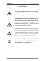
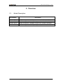
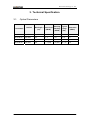
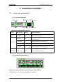
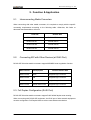
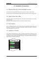
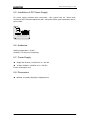
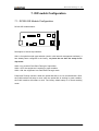
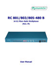
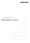
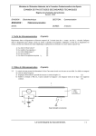
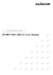
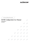
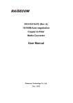
RC202-GE (Rev. B) 1000M Copper-to-Fiber Media Converter User Manual Raisecom Technology Co., Ltd. Dec, 2005 Raisecom Technology Co., Ltd. CONTENT 1. SAFETY NOTICE .................................................................................................................2 2. OVERVIEW............................................................................................................................3 2.1. 3. TECHNICAL SPECIFICATION...........................................................................................4 3.1. 4. 6. 7. OPTICAL PARAMETERS .....................................................................................................4 CONSTRUCTION & INDICATOR ......................................................................................5 4.1. 5. MODEL DESCRIPTION .......................................................................................................3 FRONT VIEW AND INDICATORS ..........................................................................................5 FUNCTION & APPLICATION .............................................................................................7 5.1. INTERCONNECTING MEDIA CONVERTERS .........................................................................7 5.2. CONNECTING MC WITH OTHER DEVICES (AT RJ45 PORT)................................................7 5.3. FULL DUPLEX CONFIGURATION (RJ45 PORT)...................................................................7 5.4. CONNECTION WITH OTHER EQUIPMENT (AT OPTICAL PORT) ............................................8 INSTALLATION & INSPECTION .......................................................................................9 6.1. MATCHING FIBER-OPTIC CABLE WITH MEDIA CONVERTER .............................................9 6.2. TYPES OF FIBER-OPTIC CABLE .........................................................................................9 6.3. RJ45 INTERFACE ..............................................................................................................9 6.4. INSTALLATION OF CHASSIS ...............................................................................................9 6.5. INSTALLATION OF DC POWER SUPPLY ............................................................................10 6.6. AMBIENCE ......................................................................................................................10 6.7. POWER SUPPLY...............................................................................................................10 6.8. DIMENSIONS ...................................................................................................................10 DIP-SWITCH CONFIGURATION ..................................................................................... 11 7.1. RC202-GE MODULE CONFIGURATION ........................................................................... 11 1 Raisecom Technology Co., Ltd. 1. Safety Notice Please read the following notice carefully before installing and using the device, Raisecom shall not be responsible for any loss that caused by violating safety notice. RC202-GE (Rev. B) has high sensitivity optical interface, so the power of optical transceiver output interface must be checked before connecting. To avoid damaging, it is not allowed that the optical power of transceiver’s output interface is higher than that of RC202-GE. RC202-GE (Rev. B) is an integrated device which has precise elements, please avoid violent shake and impact, and do not disassemble or maintain the device yourself. If it is required, please do it under the guide of our technical staff following anti static steps. Please contact us if there is any need. There must be grounding protection for the sake of safety; do not disassemble the device yourself, we regard this as you waiver your rights of repair guarantee. 2 Raisecom Technology Co., Ltd. 2. Overview 2.1. Model Description Part Number Description RC202-GE-M SNMP manageable, 1000Mbps, multimode, 0-0.55km, RJ45/DSC RC202-GE-S1 SNMP manageable, 1000Mbps, single mode, 0-25km, RJ45/DSC RC202-GE-S2 SNMP manageable, 1000Mbps, single mode, 10-60km, RJ45/DSC RC202-GE-S3 SNMP manageable, 1000Mbps, single mode, 25-100km, RJ45/DSC 3 Raisecom Technology Co., Ltd. 3. Technical Specification 3.1. Optical Parameters PART NUMBER Interface Wavelength Launch Power Receiving Sensitivity (nm) (dBmW) (dBmW) Typical Range (Km) Attenuation (dB/Km) RC202-GE-M DSC-RJ45 850 -10 ~ -3 < -15 0 ~ 0.55 3 RC202-GE-S1 DSC-RJ45 1310 -10 ~ -3 < -23 0 ~ 25 0.5 RC202-GE-S2 DSC-RJ45 1550 -3 ~ +2 (DFB) < -20 10 ~ 60 0.25 RC202-GE-S3 DSC-RJ45 1550 -3 ~ +2 (DFB) < -30 (APD) 25 ~ 100 0.25 4 Raisecom Technology Co., Ltd. 4. Construction & Indicator 4.1. Front view and indicators 1. Front view of RC202-GE: Optical Link RJ45 Link RJ45 Transmit LNK LNK TX PWR FDX RX Power RJ45 Duplex RJ45 Receive Explanation of RC202-GE indicators: Interface Optical Interface Indicator Name Indicator The Status Explanation Optical Link LNK RJ45 Link LINK RJ45 Transmit TX Flashing: Transmitting data in RJ45 interface RJ45 Receive RX Flashing: Receiving data in RJ45 interface. Full Duplex FDX Power PWR ON: Optical receive link works in good condition; OFF: Optical receive link down. ON: RJ45 links works in good condition; OFF: RJ45 link down RJ45 Interface ON: RJ45 interface works in full duplex mode; OFF: RJ45 interface works in half duplex mode; ON: Power supply works in good condition; Power Supply OFF: Power supply disconnected. 2. Front view of 16-slot chassis PWR PS1 PS2 5V 12V 5V 12V RAISECOM Explanation of the indicators on 16-slot chassis is as follows: PWR indicator: ON, chassis power supply works normal. 5 Raisecom Technology Co., Ltd. PS1-5V indicator: OFF, power supply PS1 for modules works normal, otherwise abnormal. PS1-12V indicator: OFF, power supply PS1 for fans works normal, otherwise abnormal. PS2-5V indicator: OFF, power supply PS2 for modules works normal, otherwise abnormal. PS2-12V indicator: OFF, power supply PS2 for fans works normal, otherwise abnormal. 6 Raisecom Technology Co., Ltd. 5. Function & Application 5.1. Interconnecting Media Converters When connecting with other media converters, it is required to comply with the specific connecting requirements according to the following table. Otherwise, link faults or abnormal data transmission will occur. Host Site 5.2. Remote Site RC202-GE-M RC202-GE-M RC202-GE-S1 RC202-GE-S1 RC202-GE-S2 RC202-GE-S2 RC202-GE-S3 RC202-GE-S3 Connecting MC with Other Devices (at RJ45 Port) RC202-GE-XX series media converters support MDI/MDIX auto-negotiation function. Media Converter Other Equipment Connection Mode of RJ45 Media Converter Switch Straight-through or Crossover Media Converter HUB Straight-through or Crossover Media Converter Router Straight-through or Crossover Media Converter Network Interface Card Straight-through or Crossover 5.3. Full Duplex Configuration (RJ45 Port) RC202-GE-XX series media converters support RJ45 full/half duplex auto-sensing. When connecting with RC202-GE equipment, the RJ45 port of other network equipment must be configured to Full Duplex Mode to ensure normal data transmission. 7 Raisecom Technology Co., Ltd. 5.4. Connection with Other Equipment (at Optical Port) Several mandatory conditions are required: 1. The same wavelength 2. The same bit rate (1000Mbps) 3. Matched optical power 8 Raisecom Technology Co., Ltd. 6. Installation & Inspection 6.1. Matching Fiber-Optic Cable with Media Converter RC202-GE-M series shall adopt multimode fiber, and the connector shall be DSC. RC202-GE-S1/2/3 series shall adopt single-mode fiber, and the connector shall be DSC. 6.2. Types of Fiber-Optic Cable Fiber-optic cable for multi-mode fiber port: 62.5/125um multi-mode fiber or 50/125um multi-mode fiber. Fiber-optic cable for single mode fiber port: 9/125um single mode fiber. 6.3. RJ45 Interface Cat.5 of twisted-pair shall be used. Please note that twisted-pair cables shall not be longer than 100 meters. For connection configuration, please see Chapter 2, Connection with Other Equipment (at RJ45 Port). 6.4. Installation of Chassis The chassis can be fixed onto 19” rack. The fixing accessories of chassis are in the accessory box. If fixing the chassis with the rear hole, there’ll be 3cm space between the front edge of chassis and the front edge of the rack; if fixing with the front hole, the front edges will be in the same vertical level. 19" Standard Chassis Frame 9 Raisecom Technology Co., Ltd. 6.5. Installation of DC Power Supply DC power supply provides three connectors: –48V, ground and 0V. These three connectors are connected respectively with –48V power cable, ground protection and 0V power cable. -48V 地 0V 6.6. Ambience Working temperature: -20-60℃ Humidity: 5%~90% non-condensing 6.7. Power Supply Single Slot Chassis: 115/230V AC or –48V DC 16-Slots Chassis: 115/230V AC or –48V DC Power consumption: 5W 6.8. Dimensions Modular: 91(width)*25(height)*155(depth) mm 10 Raisecom Technology Co., Ltd. 7. DIP-switch Configuration 7.1. RC202-GE Module Configuration RC202-GE module sketch: SW1 SW2 Description of the two dip-switches: SW1 is for optical module type selection (work in with network management software). It has already been configured in the factory, so please do not alter the setup of this dip-switch. SW2-1 is to monitor Fault-Pass-Through of optical link. SW2-1 OFF: the equipment is working in good condition. SW2-1 ON: the equipment is at Fault-Pass-Through mode. Fault-Pass-Through function: When the optical link fails or is not connected with a fiber, the RJ45 interface will stop to work; when the optical link is working in good condition, the RJ45 interface will restart to work. The factory default setup is in normal working mode. 11 Raisecom Technology Co., Ltd. @2005 Raisecom Technology Co., Ltd. All trademarks are the property of their respective owners. Technical information may be subject to change without prior notification. -V36 12