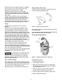
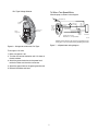
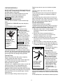
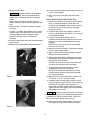
1
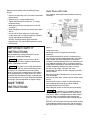
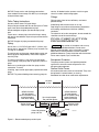
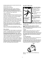
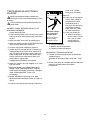
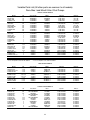
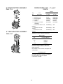
DURA-GLAS and MAX-E-GLAS™
CENTRIFUGAL PUMPS with TRAP
O
W
N
E
R’
S
M
A
N
U
A
L
1917 0895 NF
INSTALLATION, OPERATION & PARTS
Series PE, PEA, P2R, P2RA
This manual should be furnished to the end user of this pump; its use will
reduce service calls and chance of injury and will lengthen pump life.
© 2010 Pentair Water Pool and Spa, Inc. All rights reserved.
1620 Hawkins Ave., Sanford, NC 27330 • (919) 566-8000
10951 West Los Angeles Ave., Moorpark, CA 93021 • (805) 553-5000
Customer Suppport: (800) 831-7133
Sta-Rite®, Max-E-Glas™ and Pentair Water Pool and Spa® is a trademark and/or a registered trademark of Pentair Water Pool and
Spa, Inc. and/or its affiliated companies in the United States and/or other countries. Plasto-Joint Stik® is a registered trademark of
La-Co Industries, Inc. Teflon® is a registered trademark of E.I. Du Pont De Nemours and Company Corporation. Unless noted, names
and brands of others that may be used in this document are not used to indicate an affiliation or endorsement between the proprietors
of these names and brands and Pentair Water Pool and Spa, Inc. Those names and brands may be the trademarks or registered
trademarks of those partiesor others.
S413 (Rev. A)
04-15-10
‘PE’ and ‘P2R’ SERIES
PUMPS
WITH TRAP
READ AND FOLLOW
SAFETY INSTRUCTIONS!
To avoid unneeded service calls, prevent possible
injuries, and get the most out of your pump,
READ THIS MANUAL CAREFULLY!
This is the safety alert symbol. When you see this
symbol on your system or in this manual, look for
one of the following signal words and be alert to the
potential for personal injury.
The Sta-Rite ‘PE’ and ‘P2R’ Series Self-priming
Centrifugal pumps:
warns about hazards that will cause death,
serious personal
injury, or major property damage if ignored.
• Are designed for use with swimming pools or as
centrifugal pumps.
• Are excellent performers; durable, reliable.
warns about hazards that can cause death,
serious personal
injury, or major property damage if ignored.
Table of Contents
Safety Instructions ...................................................2-3
warns about hazards that will or can cause
minor personal injury or property damage if ignored.
Installation ................................................................3-5
Electrical ...................................................................5-8
NOTICE indicates special instructions not related to
hazards.
Operation................................................................9-10
Carefully read and follow all safety instructions in this
manual and on equipment. Keep safety labels in good
condition; replace if missing or damaged.
Storage/Winterizing....................................................10
Pump Service .......................................................10-11
Incorrectly installed or tested equipment
may fail, causing severe injury or property
damage. Read and follow instructions in
owner's manual when installing and
operating equipment. Have a trained pool professional
perform all pressure tests.
1. Do not connect system to a high pressure or city
water system.
2. Use equipment only in a pool or spa installation.
3. Install pump with at least 2 hydraulically balanced
main drains equipped with correctly installed, screwfastened, anti-entrapment certified covers. See Page
4.
4. Trapped air in system can cause explosion. BE SURE
all air is out of system before operating or testing
equipment.
Troubleshooting Guide...............................................12
Repair Parts List ...................................................13-15
Warranty ....................................................................16
2
INSTALLATION
Before pressure testing, make the following safety
checks:
Only qualified, licensed personnel should install pump
and wiring.
• Check all clamps, bolts, lids, and system accessories
before testing.
• Release all air in system before testing.
• Tighten Sta-Rite trap lids to 30 ft. lbs. (4.1 kg-m)
torque for testing.
• Water pressure for test must be less than 25 PSI
(7.5 kg/cm2).
• Water Temperature for test must be less than 100o F
(38o C).
• Limit test to 24 hours. After test, visually check
system to be sure it is ready for operation. Remove
trap lid and retighten hand tight only.
NOTICE: These parameters apply to Sta-Rite
equipment only. For non-Sta-Rite equipment, consult
manufacturer.
Figure 1
IMPORTANT SAFETY
INSTRUCTIONS
Pump mount must:
Be located away from corrosive or flammable
chemicals.
Have enough ventilation to maintain air temperature at
less than the maximum ambient temperature rating (Max.
Amb.) listed on the motor model plate. If this pump is
installed in an enclosure/pump house, the enclosure must
have adequate ventilation and air circulation to keep the
temperature in the enclosure at or below the motor’s rated
ambient temperature whenever the pump is running.
Be solid - Level - Rigid - Vibration free - Noncombustible. (To reduce vibration and pipe stress, bolt
pump to mount.)
Allow pump suction inlet height to be as close to water
level as possible.
Allow use of short, direct suction pipe (To reduce friction
losses).
Allow for gate valves in suction and discharge piping.
Have adequate floor drainage to prevent flooding.
Be protected from excess moisture.
Allow adequate access for servicing pump and piping.
Always follow basic safety precautions with this
equipment, including the following.
To reduce the risk of injury, do not
permit children to use this product unless they are
closely supervised at all times.
This pump is for use with permanently
installed pools and may also be used with hot tubs
and spas if so marked. Do not use with storable
pools. A permanently installed pool is constructed in
or on the ground or in a building such that it cannot
be readily disassembled for storage. A storable pool
is constructed so that it may be readily disassembled
for storage and reassembled to its original integrity.
SAVE THESE
INSTRUCTIONS
Fire and burn hazard. Modern motors run
at high temperatures. To reduce the risk of fire, do not
allow leaves, debris, or foreign matter to collect around
the pump motor. To avoid burns when handling the
motor, let it cool for 20 minutes before trying to work on
it.
NOTICE: Use Teflon tape or Plasto-Joint Stik for making
all threaded connections to the pump. Do not use pipe
dope; pipe dope will cause stress cracking in the pump.
3
NOTICE: Pump suction and discharge connections
have molded in thread stops. DO NOT try to screw pipe
in beyond these stops.
service, all flooded suction systems must have gate
valves in suction and discharge pipes.
Fittings:
Fittings restrict flow; for best efficiency use fewest
possible fittings.
Avoid fittings which could cause an air trap.
Pool fittings must conform to International Association
of Plumbing and Mechanical Officials (IAPMO)
standards.
To reduce risk of suction entrapment, do not exceed the
rated flow rate of the suction fittings.
Teflon Taping Instructions:
Use only new or clean PVC pipe fittings.
Wrap male pipe threads with one to two layers of Teflon
tape. Cover entire threaded portion of pipe.
Do not overtighten or tighten past thread stop in pump
port!
If leaks occur, remove pipe, clean off old tape, rewrap
with one to two additional layers of tape and remake the
connection.
NOTICE: Support all piping connected with pump!
POOL PUMP SUCTION
REQUIREMENTS
Piping:
Pump suction is hazardous and can trap
and drown or disembowel bathers. Do not use or
operate swimming pools, spas, or hot tubs if a suction
outlet cover is missing, broken, or loose. Follow the
guidelines below for a pump installation which minimizes
risk to users of pools, spas, and hot tubs.
Use at least 1-1/2" IPS PVC pipe with 5" (127mm) trap.
Use at least 2" pipe with 6" (152mm) trap. Increase size
if a long run is needed.
To avoid strains on the pump, support both suction and
discharge pipes independently. Place these supports
near the pump.
To avoid a strain left by a gap at the last connection,
start all piping at the pump and run pipe away from the
pump.
Never use a suction pipe smaller than pump suction
connection. To avoid
airlocking, slope suction pipe slightly upward toward the
pump.
NOTICE: To prevent flooding when removing pump for
Entrapment Protection
The pump suction system must provide protection
against the hazard of suction entrapment or hair
entrapment/entanglement.
Suction Outlet Covers
All suction outlet covers must be maintained. They must
be replaced if cracked, broken, or missing.
See below for outlet cover certification requirements.
At Least
3 Feet
IAPMO Certified
Anti-entrapment
Cover or Suction Fitting,
screw-fastened to
Main Drain Sump
No valves between
Tee and Main Drains
Suction Outlet
(Main Drain)
IAPMO Certified
Anti-entrapment
Cover or Suction Fitting,
screw-fastened to
Main Drain Sump
Suction Outlet
(Main Drain)
Pump
Valves OK between
pump and Tee
2762 0197
Figure 2 – Recommended pump suction layout.
4
ELECTRICAL
All suction outlets must have correctly installed, screwfastened covers in place.
Ground motor before
connecting to electrical
power supply. Failure to
ground motor can cause
severe or fatal electrical
shock hazard.
Testing and Certification
Suction outlet covers must have been tested by a
nationally recognized testing laboratory and found to
comply with the latest ASME/ANSI Specification for
Suction Fittings For Use in Swimming Pools, Spas, Hot
Tubs, and Whirlpool Bathtub Applications.
Do not ground to a gas
supply line.
Outlets Per Pump
Provide at least two hydraulically balanced main drains,
with covers (see Page 4), for each swimming pool pump
suction line. The centers of the main drains (suction
fittings) must be at least three feet apart.
The system must be built so that it cannot operate with
the pump drawing water from only one main drain (that
is, there must be at least two main drains connected to
the pump whenever it is running). (See Figure 2).
However, if two main drains run into a single suction
line, the single suction line may be equipped with a
valve which will shutoff both main drains from the pump
(see Figure 2).
More than one pump can be connected to a single
suction line as long as the requirements above are met.
Hazardous voltage.
Can shock, burn,
or cause death.
To avoid dangerous or
fatal electrical shock,
turn OFF power to motor
before working on electrical
connections.
Ground pump before
connecting to
power supply.
Ground Fault Circuit
Interrupter (GFCI)
tripping indicates an electrical
problem. If GFCI trips and will
not reset, have a qualified electrician inspect and repair
electrical system.
Exactly match supply voltage to nameplate
voltage. Incorrect voltage can cause fire or
seriously damage motor and voids warranty. If in doubt
consult a licensed electrician.
Water Velocity
Voltage
The maximum water velocity through any suction outlet
must be 1.5 feet per second unless the outlet complies
with the latest ASME/SNSI Specification for Suction
Fittings For Use in Swimming Pools, Spas, Hot Tubs,
and Whirlpool Bathtub Applications. In any case, do not
exceed the suction fittings maximum designed flow rate.
If 100% of the pump’s flow comes from the main drain
system, the maximum water velocity in the pump
suction hydraulic system must be six feet per second or
less even if one main drain (suction fitting) is completely
blocked. The flow through the remaining main drain(s)
must comply with the latest ASME/ANSI Specification
for Suction Fittings For Use in Swimming Pools, Spas,
Hot Tubs, and Whirlpool Bathtub Applications.
Voltage at motor must be not more than 10% above or
below motor nameplate rated voltage or motor may
overheat, causing overload tripping and reduced component
life. If voltage is less than 90% or more than 110% of rated
voltage when motor is running at full load, consult power
company.
Grounding/Bonding
Install, ground, bond and wire motor according to local
or National Electrical Code requirements.
Permanently ground motor. Use green ground terminal
provided under motor canopy or access plate (See Fig.
3); use size and type wire required by code. Connect
motor ground terminal to electrical service ground.
BONDING
LUG
GREEN
GROUND
SCREW
510 0993
Figure 3 – Typical ground screw and bonding lug
locations.
5
Remove Motor End Cover
Ground wire must be a copper conductor. It should be
the same size as the current-carrying wires to the
motor, but not smaller than No. 12 AWG.
Bond motor to pool structure. Use a solid copper
conductor, size No. 8 AWG (8.4 sq. mm) or larger. Run
wire from external bonding lug (see Fig. 3) to reinforcing
rod or mesh.
Connect a No. 8 AWG (8.4 sq. mm) solid copper
bonding wire to the pressure wire connector provided
on the motor housing and to all metal parts of the
swimming pool, spa, or hot tub and to all electrical
equipment, metal piping or conduit within 5 feet (1.5 m)
of the inside walls of swimming pool, spa, or hot tub.
If you have a dual-voltage motor, and will connect it to
115 volts, follow the procedure below.
Wiring
NOTICE: For 575 volt models, consult a licensed
electrician.
NOTICE: 3 phase models require magnetic motor
starters and external overload protection. If in doubt
about the procedure, consult a licensed electrician.
Pump must be permanently connected to circuit. See
Figures 4A, and 4B for wiring connection diagrams. See
Table I, Page 8, for correct wire and circuit breaker
sizes for the pump alone. If other lights or appliances
are also on the same circuit, be sure to add their amp
loads to pump amp load before figuring wire and circuit
breaker sizes. (If unsure how to do this or if this is
confusing, consult a licensed electrician.) Use the load
circuit breaker as the master on-off switch.
Install a Ground Fault Circuit Interrupter (GFCI) in
circuit; it will sense a short-circuit to ground and
disconnect power before it becomes dangerous to pool
users. For size of GFCI required and test procedures for
GFCI, see manufacturer’s instruction.
In case of power outage, check GFCI for tripping (which
will prevent normal pump operation). Reset if
necessary.
Figure 4 - Removing motor end cover.
You will need to remove the motor end cover to change
the voltage setting.
Your motor terminal board (located under the motor end
cover) should look like one of those below.
Plug Type Voltage Selector
Ground
Screw
Voltage Change
Plug
Power Lead
Terminals
Risk of dangerous or fatal electrical shock.
Be sure that power to the motor circuit is off before
working on wiring, wiring connections, or motor. Reinstall the motor end cover and all other wiring covers
before turning on the power.
Figure 5 – Voltage set to 230 volts, Plug Type.
To change to 115 volts:
1. Make sure power is off.
Motor Switch Settings
Dual-voltage motors (motors that can operate at either
115 or 230 volts), are set at the factory to 230 volts. Do
not change motor voltage setting if line voltage is 230
volts, or if you have a single voltage motor.
NOTE: Never wire a 115 volt motor to a 230 volt line.
2. Pull the plug straight up.
3. Move and attach the plug at the 115 volt position.
The plug will now cover 2 metal tabs. The arrow on
the plug will point to 115V.
4. Attach the power lead wires to the power lead
terminals. Make sure the wires are secure.
5. Attach the ground wire to the green ground screw
6. Reinstall the Motor end cover
6
To Wire a Two-Speed Motor
Dial Type Voltage Selector
Wire the pump as shown in the diagram.
Ground (Green)
Ground
Screw
Low Speed
230
Volt
Lines
Voltage
Change Dial
Power Lead
Terminals
L2=COM
L1=HI
A=LOW
A
Back of
motor
with
Terminal
Board
L2
Common
Power Supply for
Optional Timer.
L1
High Speed
Remote
SPDT
Switch
If using timer, Connect
Timer Motor to Low Speed Only
Circuit
Protector
4558 0304
Minimum switch and timer amp rating must equal Branch Fuse
Rating given in "Recommended Fusing and Wiring Data" table.
Figure 7 – 2-Speed motor wiring diagram.
Figure 6 – Voltage set to 230 volts, Dial Type.
To change to 115 volts:
1. Make sure power is off.
2. Turn the dial counter-clockwise until 115 shows in
the dial window.
3. Attach the power lead wires to the power lead
terminals. Make sure the wires are secure.
4. Attach the ground wire to the green ground screw
5. Reinstall the Motor end cover
7
TABLE I – ELECTRICAL DATA - FUSING AND WIRING REQUIREMENTS
Dura-Glas I and Max-E-Glas I Pool Pumps
Single-Speed Models
Model
Motor
HP
Voltage/
Hz/Phase
PE52C-180L
PE5C-180L
P2R5C-180L
P2RA5C-179L
PE52D-181L
PE5D-181L
PEA5D-180L
PEAXSSD-180
P2R5D-181L
P2RA5D-180L
71532
PE52E-182L
PE5E-182L
PEA5E-181L
PEAXSSE-181
P2FA5E-180L
P2R5E-182L
P2RA5E-181L
71808
PEA5F-182L
PEA6F-182L
PEAXSSF-182
P2FA5F-181L
P2RA5F-182L
PE52F-183L
PEAXSSG-183
P2RA6G-183L
P2RAXG-183LS
PEAAXSSG-184
PE6H-185L, LC
1/2
1/2
1/2
1/2
3/4
3/4
3/4
3/4
3/4
3/4
3/4
1
1
1
1
1
1
1
1
1-1/2
1-1/2
1-1/2
1-1/2
1-1/2
1-1/2
2
2
2
2-1/2
3
100/200/60/1
115/230/60/1
115/230/60/1
230/60/1
100/200/60/1
115/230/60/1
115/230/60/1
115/230/60/1
115/230/60/1
115/230/60/1
115/230/60/1
200/60/1
115/230/60/1
115/230/60/1
115/230/60/1
115/230/60/1
115/230/60/1
115/230/60/1
115/230/60/1
115/230/60/1
115/230/60/1
115/230/60/1
115/230/60/1
115/230/60/1
200/60/1
230/60/1
230/60/1
230/60/1
230/60/1
230/60/1
Max Load Branch Fuse
Amps
Rating Amps*
12.0/6.0
9.6/4.8
13.4/6.7
9.9/5.0
13.4/6.7
13.8/6.9
11.0/5.5
9.6/4.8
15.3/7.6
13.4/6.7
13.4/6.7
8.5
16.0/8.0
13.8/6.9
12.6/6.3
13.4/6.7
18.2/9.1
15.3/7.6
15.3/7.6
16.0/8.0
16.0/8.0
16.0/8.0
15.3/7.6
18.2/9.1
10.5
10.4
12.0
12.0
11.2
15.8
15/15
15/15
20/15
15/15
20/15
20/15
15/15
15/15
20/15
20/15
20/15
15
25/15
20/15
20/15
20/15
30/15
20/15
20/15
30/15
30/15
30/15
20/15
30
15
15
20
20
20
25
Serv. to Motor - Dist. in Ft. (M)
0-100'
101-200'
201-300'
(0-30M)
(30-60M)
(60-90M)
14/14(2/2)
14/14(2/2)
12/14(2/3)
14/14(2/2)
12/14(3/2)
12/14(3/2)
14/14(2/2)
14/14(2/3)
12/14(3/2)
12/14(3/2)
12/14(3/2)
14(2)
12/14(3/2)
12/14(3/2)
12/14(3/2)
12/14(3/2)
10/14(5.5/2)
12/14(3/2)
12/14(3/2)
12/14(3/2)
12/14(3/2)
12/14(3/2)
12/14(3/2)
10/14(5.5/2)
14(2)
14(2)
14(2)
14(2)
14(2)
12(3)
10/14(5.5/2)
10/14(5.5/2)
10/14(5.5/2)
12/14(3/2)
10/14(5.5/2)
10/14(5.5/2)
10/14(5.5/2)
10/14(5.5/2)
8/14(8.4/2)
10/14(5.5/2)
10/14(5.5/2)
14(2)
8/14(8.4/2)
10/14(5.5/2)
10/14(5.5/2)
10/14(5.5/2)
8/14(8.4/2)
8/14(8.4/2)
8/14(8.4/2)
8/14(8.4/2)
8/14(8.4/2)
8/14(8.4/2)
8/14(8.4/2)
8/14(8.4/2)
12(3)
14(2)
14(2)
14(2)
14(2)
12(3)
8/12(8.4/3)
10/14(5.5/2)
8/14(8.4/2)
8/14(8.4/2)
8/14(8.4/2)
8/14(8.4/2)
8/14(8.4/2)
10/14(5.5/2)
6/14(14/2)
8/14(8.4/2)
8/14(8.4/2)
12(3)
6/12(14/3)
8/12(8.4/2)
8/14(8.4/2)
8/14(8.4/2)
6/12(14/3)
6/14(14/2)
6/14(14/2)
6/14(14/2)
6/14(14/2)
6/14(14/2)
6/14(14/2)
6/12(14/3)
12(3)
12(3)
12(3)
12(3)
12(3)
10(5.5)
Two-Speed Models
Model
PEXYD-194L
PEAXYE-181L
P2RA5YE-181L, LC
P2RA5YE-194L
P2RA5YF-182L
P2RA5YF-196L
P2RA6YF-182L
PEAXYG-183L
PEAXYG-183LS
P2RA5YG-183L
Motor
HP
Voltage/
Hz/Phase
3/4–1/8
1–1/6
1–1/6
1–1/6
1-1/2–1/4
1-1/2–1/4
1-1/2–1/4
2–1/3
2–1/3
2–1/3
115/60/1
230/60/1
230/60/1
115/60/1
230/60/1
115/60/1
115/60/1
230/60/1
230/60/1
230/60/1
Max Load Branch Fuse
Amps
Rating Amps*
12.0/4.0
5.3/2.0
7.3/2.6
14.5/5.0
9.2/2.5
18.7/5.1
18.7/5.1
10.1/3.7
10.1/3.7
10.1/3.7
15
15
15
20
15
25
25
15
15
15
Serv. to Motor - Dist. in Ft. (M)
0-100'
101-200'
201-300'
(0-30M)
(30-60M)
(60-90M)
14(2)
14(2)
14(2)
12(3
14(2)
10(5)
10(5)
14(2)
14(2)
14(2)
10(5)
14(2)
14(2)
8(8.4)
14(2)
8(8.4)
8(8.4)
14(2)
14(2)
14(2)
8(8.4)
14(2)
14(2)
6(14)
12(3)
6(14)
6(14)
12(3)
12(3)
12(3)
Three Phase Models
Model
P2RA5C3-179
P2R5D3-181
P2R52D3-181
P2R5E3-182
P2R52E3-182
P2R5F3-183
P2R52F3-183
P2R5G3-184
P2R52G3-184
PE6H3-185
Motor
HP
Voltage/
Hz/Phase
1/2
3/4
3/4
1
1
1-1/2
1-1/2
2
2
3
208-230/460/60/3
230/460/60/3
200/400/60/3
230/460/60/3
200/400/60/3
230/460/60/3
200/400/60/3
230/460/60/3
200/400/60/3
230/460/60/3
Max Load Branch Fuse
Amps
Rating Amps*
2.3/1.15
3.6
3.8/1.9
4.7
5.6/2.8
5.8
6.6/3.3
7.0
8.0/4.0
9.7/4.9
15/15
15
15/15
15
15/15
15
15/15
15
15/15
15/15
NOTICE: For 575 volt models, consult a licensed electrician.
8
Serv. to Motor - Dist. in Ft. (M)
0-100'
101-200'
201-300'
(0-30M)
(30-60M)
(60-90M)
14/14(2/2)
14/14(2/2)
14/14(2/2)
14/14(2/2)
14/14(2/2)
14/14(2/2)
14/14(2/2)
14/14(2/2)
14/14(2/2)
14/14(2/2)
14/14(2/2)
14/14(2/2)
14/14(2/2)
14/14(2/2)
14/14(2/2)
14/14(2/2)
14/14(2/2)
14/14(2/2)
14/14(2/2)
14/14(2/2)
14/14(2/2)
14/14(2/2)
14/14(2/2)
14/14(2/2)
14/14(2/2)
14/14(2/2)
14/14(2/2)
14/14(2/2)
14/14(2/2)
12/14(3/2)
OPERATION
Replace trap cover on trap; turn clockwise to tighten
cover.
NOTICE: Tighten trap cover by hand only (no
wrenches)!
Pump should prime now. Priming time will depend on
vertical length of suction lift and horizontal length of
suction piping.
If pump does not prime, make sure that all valves are
open, suction pipe end is under water, pump suction is
below water level, and that there are no leaks in suction
pipe. See Troubleshooting Guide, Page 12.
NOTICE: NEVER run pump dry. Running pump dry may
damage seals, causing leakage and flooding. Fill pump
with water before starting motor.
NOTICE: Maximum ambient temperature for motor
operation must not exceed maximum ambient
temperature rating on motor model plate.
Before removing trap cover:
1. STOP PUMP before proceeding.
2. CLOSE GATE VALVES in suction and discharge
pipes.
3. RELEASE ALL PRESSURE from pump and piping
system.
4. NEVER tighten or loosen clamp while pump is
operating.
If pump is being
pressure tested,
release all pressure before
removing trap cover.
Do not block pump
suction. To do so with
body may cause severe or
fatal injury. Small children
using pool must ALWAYS
Hazardous suction.
Can trap hair or
have close adult supervision.
Routine Maintenance
The only routine maintenance needed is
inspection/cleaning of trap basket. Debris or trash that
collects in basket will choke off water flow through the
pump. Follow instructions below to clean trap:
1. Stop pump, close valves in suction and discharge,
and release all pressure from system before
proceeding.
2. Unscrew trap lid (turn counterclockwise). If
necessary, use a lever such as a board or long
screwdriver between lugs on trap cover.
3. Remove strainer basket and clean. Be sure all holes
in basket are clear, flush basket with water and
replace in trap.
4. Clean and inspect “O” Ring; reinstall on trap cover.
5. Clean “O” Ring groove on trap body and replace lid.
To help keep lid from sticking, tighten hand tight only
(no wrenches!).
6. Prime pump (see priming
instructions, above).
body parts, causing
severe injury
or death.
Fire and burn
hazard. Modern motors run
at high temperatures. To
Do not block
reduce the risk of fire, do not
suction.
allow leaves, debris, or
foreign matter to collect
around the pump motor. To avoid burns when handling
the motor, let it cool for 20 minutes before trying to work
on it. An automatic internal cutoff switch protects single
phase motors from heat damage during operation.
Draining Pump
1. Pump down water level
below all inlets to the pool.
To avoid dangerous or
fatal electrical shock
hazard, turn OFF power to
motor before draining pump.
2. To prevent pump from
freezing, remove the trap
Hazardous voltage.
Can shock, burn,
cover and drain the tank
or cause death.
body through the drain
plug (Key No. 15, Page
Disconnect power
13). Clean pump
before working
thoroughly; replace trap
on pump or motor.
cover.
NOTICE: Tighten trap cover by hand only (no wrenches)!
Use a lever or wrench only if necessary to remove cover!
If pump is not anchored, use caution to not break attached
piping!
3. Use Sta-Rite U79-11 Lid Wrench to remove trap covers
Priming Pump
Release all pressure from filter, pump, and piping
system; see the filter owner’s manual.
In a flooded suction system (water source higher than
pump), pump will prime itself when suction and
discharge valves are opened.
If pump is not in a flooded suction system, unscrew and
remove trap cover; fill trap and pump with water.
Do not lubricate the trap cover O-Ring. The original
equipment O-Ring contains a permanent internal lubricant.
NOTICE: If you replace the O-Ring with a non-internally
lubricated O-Ring, you may need to apply a silicone
based lubricant.
Clean and inspect O-Ring; reinstall on trap cover.
9
that have been overtightened or have taken a set and
cannot be removed by hand. Lugs have been provided
on the trap lid to use a lever or pry bar for loosening.
4. Cap inlet piping after draining to keep water out of
the pipes.
5. Be sure motor is kept dry and covered.
9. Prime pump according to instructions on Page 9.
PUMP
SERVICE
Pump should only be
serviced by qualified
personnel.
Storage/Winterizing:
For best results, use only
genuine Sta-Rite factory
parts.
Explosion hazard. Purging the system with
compressed air can cause components to explode, with
risk of severe injury or death to anyone nearby. Use only
a low pressure (below 5 PSI), high volume blower when
air purging the pump, filter, or piping.
Be sure to prime pump (Page
9) before starting.
Hazardous voltage.
Can shock, burn,
or cause death.
Pool chemicals may give off corrosive
fumes. Store chemicals away from pump in a well
ventilated area.
NOTICE: Allowing pump to freeze will damage pump
and void warranty!
NOTICE: Do not use anti-freeze solutions (except
propylene glycol) in your pool/spa system. Propylene
glycol is non-toxic and will not damage plastic system
components; other anti-freezes are highly toxic and may
also damage plastic components in the system.
Drain all water from pump and piping when expecting
freezing temperatures or when storing pump for a long
time (see instructions below).
Keep motor dry and covered during storage.
To avoid condensation/corrosion problems, do not
cover pump with plastic.
For outdoor/unprotected installations:
1. Gravity drain system as far as possible.
2. Protect areas which retain water with non-toxic
propylene glycol antifreeze (“RV antifreeze”).
3. Enclose entire system in a weatherproof enclosure.
4. To avoid condensation/corrosion damage, allow
ventilation; do not wrap system in plastic.
5. Use a 40% propylene glycol/60% water solution to
protect pump to -50 degrees F (-46 degrees C).
Disconnect power
before working
on pump or motor.
Before removing trap
cover:
1. STOP PUMP before
proceeding.
2. CLOSE GATE VALVES in
suction and discharge
pipes.
3. RELEASE ALL PRESSURE from pump and piping
system.
4. NEVER tighten or loosen clamp while pump is
operating.
To avoid dangerous or fatal electrical shock
hazard, turn OFF power to motor before working
on pump or motor.
Aside from lubricating trap cover O-Ring, no lubrication
or regular maintenance is needed beyond reasonable
care and periodic cleaning.
If shaft seal is worn or damaged, repair as follows:
Pump Disassembly/Removing Old Seal
Disconnect power to pump motor.
Be sure gate valves on suction and return piping
are closed before starting work.
Release all pressure by opening all vents before
starting work.
1. Drain pump by removing drain plugs on bottom of
pump body and trap body.
Startup For Winterized Equipment
1. Remove any temporary weather protection placed
around system.
2. Follow filter manufacturer’s instructions for
reactivation of the filter.
3. Inspect all electrical wiring for damage or
deterioration over the shutdown period. Have a
qualified serviceman repair wiring as needed.
4. Inspect and tighten all watertight connections.
5. Open all valves in suction and return piping.
6. Remove any winterizing plugs in piping system.
7. Drain all antifreeze from system.
8. Close all drain valves and replace all drain plugs in
piping system.
2. After making sure that there is no pressure in trap
body, remove cover
(unscrew by turning counterclockwise).
3. Remove clamp holding pump halves together.
4. Remove pump base mounting bolts, if used. Motor
and seal plate assembly can now be pulled away
from pump body.
5. Remove five screws and washers holding diffuser to
seal plate.
10
6. Remove motor canopy.
10. Place seal plate face down on flat surface and tap out
ceramic seat (Figure 8).
11. Clean seal cavity in seal plate and clean motor
shaft.
Capacitor voltage can be dangerous.
Before proceeding, short the capacitor terminals
together with a screwdriver that has an insulated
handle.
Being careful not to touch capacitor terminals,
loosen capacitor clamp and move capacitor to one
side.
7. Hold shaft with 7/16" open-end wrench on motor
shaft flats.
NOTICE: On models with impeller screw, remove
impeller screw (left hand thread - turn clockwise)
and gasket before removing impeller. Inspect
gasket for damage, cracks, etc. Replace if
damaged.
8. Unscrew impeller from shaft (turn counterclockwise
when facing it).
9. Remove four screws holding seal plate to motor.
Pump Reassembly/Installing New Seal
1. Ceramic seat must be clean and free of dirt, grease,
dust, etc. Wet outer edge of O-Ring with small
amount of liquid detergent; press ceramic seat into
seal plate cavity firmly and squarely with finger
pressure (Figure 9).
2. If ceramic seat will not locate properly, remove it,
place face up on bench and reclean cavity. Ceramic
seat should now locate.
3. If seat still will not locate properly, place a
cardboard washer over the polished face and use a
piece of 3/4" (19mm) standard pipe for pressing
purposes.
NOTICE: Be sure not to scratch or mar polished
surface or seal will leak.
4. Remount seal plate on motor. Tighten bolts to 60-80
inch-lbs. (69-92 kg/cm) torque.
5. Apply a small amount of liquid detergent to inside
diameter of rotating half of seal.
6. Slide rotating seal member, polished face last, over
threaded shaft end and shaft shoulder until rubber
drive ring hits shaft shoulder.
NOTICE: Be sure not to nick or scratch polished
seal face; seal will leak if face is damaged.
7. Screw impeller onto shaft (clockwise); this will
automatically locate seal in seal plate.
NOTICE: On models with impeller screw: install
impeller gasket and lock screw (left-hand thread –
turn counterclockwise).
8. Mount diffuser on seal plate; tighten screws to 1014 inch-lbs. (11.5-16.1 cent.-kg.) torque.
9. Assemble motor and seal plate to volute; be sure
clamp is properly seated. NOTICE: Clamp knob can
be located in any position around volute; if it is
moved after assembly, tighten knob while tapping
around clamp to assist sealing. Do not move clamp
while pump is full of water.
Figure 8
Hazardous pressure. Release all pressure
from pump and piping system before working on pump
or attempting to adjust or remove clamp. Clamp may
blow off of pump if adjusted under pressure.
10. Reinstall pump base mounting bolts (if used) and
prime pump according to instructions on Page 9.
Figure 9
11
TROUBLESHOOTING
GUIDE
water. If so, a “higher
head” pump is needed.
Electrical:
10. Pump may be running too
slowly; check voltage at
motor terminals and at
meter while pump is
running. If low, see wiring
instructions or consult
power company. Check
for loose connections.
Hazardous voltage.
11. Pump may be too hot.
Can shock, burn,
A. Check line voltage; if
or cause death.
less than 90% or more
Disconnect power
than 110% of rated
before working
on pump or motor.
voltage consult a
licensed electrician.
B. Increase ventilation.
Read and understand safety and operating
instructions in this manual before doing any work
on pump!
Only qualified personnel should electrically test
pump motor!
FAILURE TO PUMP; REDUCED CAPACITY OR
DISCHARGE PRESSURE
Suction leaks/lost prime:
1. Pump must be primed; make sure that pump volute
and trap are full of water. See priming instructions,
Page 9.
2. Make sure there are no leaks in suction piping.
3. Make sure suction pipe inlet is well below the water
level to prevent pump from sucking air.
4. If suction trap gasket is defective, replace it.
5. Suction lift of 15 to 25 feet (4.5 to 7.5 meters) will
reduce performance. Suction lift of more than 25
feet (7.5 meters) will prevent pumping and cause
pump to lose prime. In either case, move pump
closure (vertically) to water source. Make sure
suction pipe is large enough.
Clogged pipe/trap/impeller, worn impeller:
6. Make sure suction trap is not clogged; if it is, clean
trap and strainer.
7. Make sure impeller is not clogged (follow steps 1
through 7 under “Removing Old Seal”, Page 10;
check impeller for clogging; follow steps 7 through 9
under “Installing New Seal”, Page 11, for
reassembly).
8. Impeller and diffuser may be worn. If so, order
replacement parts from Repair Parts List, Pages 13
and 14.
C. Reduce ambient temperature.
D. Tighten any loose connections.
MECHANICAL TROUBLES AND NOISE
1. If suction and discharge piping are not adequately
supported, pump
assembly will be strained. See “Installation”, Page
3.
2. Do not mount pump on a wooden platform! Securely
mount on concrete platform for quietest
performance.
9. Pump may be trying to push too high a column of
12
REPAIR PARTS LIST
DURA-GLAS POOL PUMP
MAX-E-GLAS POOL PUMP
1/2 through 3 HP Models
1
2 3
4
5
6
20
8
7
9
17
19
18
10
14
13
16
Key
No.
1
2
3
4
5
6
7
8
•
9
10
11
12
13
14
15
16
17
18
19
20
•
•
•
•
•
•
•
Part
Description
Motor
Screw, #10-32x1/2"
Bonding Lug
Water Slinger
Seal Plate
O-Ring
Shaft Seal
Clamp
Clamp Knob
Impeller
Diffuser*
Screw, #8-32x7/8"
Washer, #8 Lock
Diffuser O-Ring
Tank Body
1/4” NPT Drain Plug
Base w/Motor Pad*
Motor Pad*
Washer, Flat
Screw, 3/8-16x1-3/4" Hex Hd.**
Screw, 3/8-16x1" Hex Hd.***
Reducer 2"x1-1/2"
Decal “IMPORTANT-Do not
use pipe dope...”
Motor Nameplate
Tag, “CAUTION”
Tag, “WARNING”
Tag, “CAUTION, WARNING
(bonding)”
Nameplate
12
Qty.
1
1
1
1
1
1
1
1
1
1
1
5
5
1
1
1
1
1
2
2
2
1
1
11
Part
No.
Chart, Page 14
U30-692SS
U17-568
C69-2
C203-193P
U9-228A
17304-0100S
C19-37A
WC36-22
Chart, Page 14
Chart, Page 14
U30-542SS
U43-21SS
U9-226
C176-47P1
U178-920P
C104-42P
C35-11
U43-42SS
U30-77SS
U30-74SS
C78-7P
2766 0197
15
PE5, PE52, P2R5, P2RA5, and P2R52 models include
5" trap, Pkg. 115.
WC27-27
32155-7117
61002-0002
61002-0012
PE6 and P2RA6 models include 6" trap, Pkg. 161.
PEX, PEAX, P2RX and P2RAX models do not include trap.
To meet NSF Standard 50 requirements, these pumps
must be installed with an NSF listed hair and lint strainer.
C63-12
U33-121
For trap parts, see Page 15.
• Not illustrated.
* Models with “LS” suffix use Steel Base, Part No. J104-9C, and Motor Pad Part No.
C35-5.
** Not used on models with “LS” suffix.
*** Models with “LS” suffix use 4 3/8x16x1" Capscrews Part No. U30-74SS.
13
Variable Parts List (All other parts are common to all models)
Dura-Glas I and Max-E-Glas I Pool Pumps
SINGLE SPEED MODELS
Model
PE5C-180L
PE52C-180L
P2R5C-180L
P2RA5C-179L
PE52D-181L
PE5D-181L
PEA5D-180L
PEAXSSD-180
P2R5D-181L
P2RA5D-180L
71532
PE52E-182L
PE5E-182L
PEA5E-181L
PEAXSSE-181
P2FA5E-180L
P2R5E-182L
P2RA5E-181L
71808
PEA5F-182L
PEA6F-182L
PEAXSSF-182
P2FA5F-181L
P2RAXF-182LS
PE52F-183L
PEAXSSG-183**
P2RA6G-183L
P2RAXG-183L, LS
PEAAXSSG -184**
PE6H-185L, LC*
HP
Volts/Hz/Ph
Motor
Impeller
Diffuser
1/2
1/2
1/2
1/2
3/4
3/4
3/4
3/4
3/4
3/4
3/4
1
1
1
1
1
1
1
1
1-1/2
1-1/2
1-1/2
1-1/2
1-1/2
1-1/2
2
2
2
2-1/2
3
115/230/60/1
100/200/60/1
115/230/60/1
115/230/60/1
100/200/60/1
115/230/60/1
115/230/60/1
115/230/60/1
115/230/60/1
115/230/60/1
115/230/60/1
100/200/60/1
115/230/60/1
115/230/60/1
115/230/60/1
115/230/60/1
115/230/60/1
115/230/60/1
115/230/60/1
115/230/60/1
115/230/60/1
115/230/60/1
115/230/60/1
115/230/60/1
200/60/1
230/60/1
230/60/1
230/60/1
230/60/1
230/60/1
AE100CHL
AE100CH2
A100CHL
A100CLL
AE100DH2
AE100DHL
AE100DLL
AE100DLL
A100DHL
A100DLL
A100DLL
AE100EH2
AE100EHL
AE100ELL
AE100ELL
A100ESLL
A100EHL
A100ELL
A100ELL
AE100FLL
AE100FLL
AE100FLL
A100FSLL
A100FLL
AE100FH2
AE100GLL
A100GLL
A100GLL
AE100G5LL
AE100HLL
C105-92PS
C105-92PS
C105-92PS
C105-92PR
C105-138PEB
C105-138PEB
C105-92PS
C105-92PSC
C105-138PEB
C105-92PS
C105-92PS
C105-137PEB
C105-137PEB
C105-138PEB
C105-138PEBB
C105-92PS
C105-137PEB
C105-138PEB
C105-138PEB
C105-137PEB
C105-137PEB
C105-137PEB1
C105-138PEB
C105-137PEB
C105-137PDBA
C105-137PDB1A
C105-137PDBA
C105-137PDBA
C105-137PD1A
C105-137PKBA
C1-216P
C1-216P
C1-216P
C1-217P1
C1-200PA
C1-200PA
C1-216P
C1-216PB
C1-200PA
C1-216P
C1-216P
C1-200PA
C1-200PA
C1-200PA
C1-200PAB
C1-216P
C1-200PA
C1-200PA
C1-200PA
C1-200PA
C1-200PA
C1-200PAB
C1-200PA
C1-200PA
C1-200PA
C1-200PAB
C1-200PA
C1-200PA
C1-200PAB
C1-259P
* Uses one impeller screw, Part No. C30-12.
** Uses one impeller screw, Part No. C30-47.
TWO-SPEED MODELS
Model
PEXYD-194L
PEAXYE-181L
P2RA5YE-181L,LC
P2RA5YE-194L
P2RA5YF-182L*
P2RA6YF-182L
P2RA5YF-196L
PEAXYG-183L
P2RA5YG-183L*
PEAXYG-183LS
HP
Volts/Hz/Ph
Motor
Impeller
Diffuser
3/4–1/8
1–1/6
1–1/6
1–1/6
1-1/2–1/4
1-1/2–1/4
1-1/2–1/4
2–1/3
2–1/3
2–1/3
115/60/1
230/60/1
230/60/1
115/60/1
230/60/1
230/60/1
115/60/1
230/60/1
230/60/1
230/60/1
AE100ELL-Y
62003-2001
A100ELL-Y
AE100SLL-Y
A100FLL-Y
A100FSLL-Y
A100FSLL-Y
AE100GLL-Y
AE100GLL-Y
AE100GLL-Y
C105-138PEBA
C105-138PEB
C105-138PEB
C105-138PEB
C105-137PEBA
C105-137PEBA
C105-137PEBA
C105-138PDBA
C105-137PDBA
C105-138PDBA
C1-200PA
C1-200PA
C1-200PA
C1-200PA
C1-200PA
C1-200PA
C1-200PA
C1-200PA
C1-200PA
C1-200PA
Impeller
C105-92PRA
C105-138PEBA
C105-138PEBA
C105-137PEBA
C105-137PEBA
C105-137PDBA
C105-137PDBA
C105-137PEBA
C105-137PDA
C105-137PDA
C105-137PDBA
C105-137PDBA
C105-137PKBA
Diffuser
C1-217P
C1-200PA
C1-200PA
C1-200PA
C1-200PA
C1-200PA
C1-200PA
C1-200PA
C1-200PA
C1-200PA
C1-200PA
C1-200PA
C1-200PA
* Uses one impeller screw, Part No. C30-12.
THREE-PHASE MODELS
Model
P2RA5C3-179*
P2R5D3-181*
P2R52D3-181*
P2R5E3-182*
P2R52E3-181*
P2R5F3-183*
P2R52F3-183*
P2RA5F36-182*
P2R5G3-184*
P2R52G3-184*
PE5G36-184*
P2RA5G36-183*
PE6H3-185*
HP
1/2
3/4
3/4
1
1
1-1/2
1-1/2
1-1/2
2
2
2
2
3
Volts/Hz/Ph
208–230/460/60/3
208–230/460/60/3
200/400/3
208–230/460/60/3
200/400/3
208–230/460/60/3
200/400/3
575/60/3
230/460/60/3
200/400/3
575/60/3
575/60/3
200–230/460/60/3
Motor
AP100CL
AP100DH
AP100DH2
AP100EH
AP100EH2
AP100FH
AP100FH2
62001-1019
AP100GH
AP100GH2
62003-2087
62003-2087
AP100HL
* Uses one impeller screw, Part No. C30-12.
14
5" TRAP/ADAPTER ASSEMBLY
PKG. 115
REPAIR PARTS LIST - 5" and 6"
TRAPS*
1
Key
No.
2
1
2
3
4
5
6
Trap Cover
O-Ring - Cover
Strainer Basket
Trap Body
Gasket
Pipe Plug - 1/4" NPT
(w/O-Ring)
7 Capscrew-5/16-18x1-1/4"
64SS(4)
8 Washer, Lock 5/16"
11SS(4)
9 Washer, Flat 5/16"
41SS(4)
3
4
5
6
6A
9
1844 0695
8
7
6" TRAP/ADAPTER ASSEMBLY
PKG. 161
C3-139P1
U9-229
C108-33P
C153-53P1
C20-123
U178-920P
16920-0011
16920-0012
16920-0017
C153-58P
C20-123
U178-920P
U30-64SS(4)
U30-
U43-11SS(4)
U43-
U43-41SS(4)
U43-
*Quantity one unless otherwise indicated ( ).
Overhaul Kits
1
2
3
H.P.
Parts-Pak Number
1/2
3/4
1
1-1/2
PP1011
PP1014
PP1016
PP1018
Kit includes: Impeller, Diffuser, Shaft Seal,
Gaskets, O-Rings, Hardware, Shims, Wear
Rings and Inserts.
Not available for two and three horsepower PE
series pumps.
4
5
9
Part No.
Pkg. 115
Pkg. 161
5" Trap
6" Trap
Part
Description
1843 0695
8
7
Seal/Gasket Kit
6
6A
Kit includes Shaft Seal, Gaskets, and O-Rings.
For all horsepower PE series pumps.
Parts-Pak No. PP1000.
15
*S413*
S413 (Rev. A) 04-15-10


![4403002491_712_716 menu_EN_A [s]](http://vs1.manualzilla.com/store/data/005650300_1-96030b29e24dd373b0bced3bef593dda-150x150.png)