1
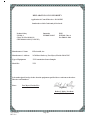
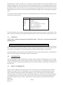
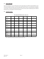
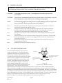
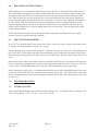
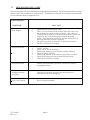
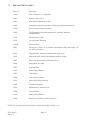
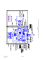
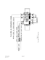
MicroTUV ONLINE UV
TRANSMISSION SENSOR/SAMPLER
OPERATION & MAINTENANCE
MANUAL
HF scientific, inc.
3170 Metro Parkway
Fort Myers, FL 33916-7597
Phone: (239) 337-2116
Fax: (239) 332-7643
Catalog #22416 (4/03)
TABLE OF CONTENTS
1.0
I M P O R T A N T I N F O R M A T I O N ......................................................... 1
1.1
1.2
13
2.0
Page No.
H O W T O U S E T H I S M A N U A L ............................................................... 1
S P E C I F I C A T I O N S FOR THE TUV SENSOR/SAMPLER........................... 1
TUV SYSTEM .......................................................................................................... 1
I N S T A L L A T I O N .................................................................................... 2
2 . 1 P A C K I N G L I S T F O R T H E TUV -------------------------------------------------------- 2
2.2
U N P A C K I N G A N D I N S P E C T I O N .......................................................... 2
2.3
M O U N T I N G ................................................................................................ 2
2 . 3 . 1 S e n s o r / S a m p l e r P o w e r .................................................................. 2
2 . 3 . 2 In s t a l l i n g t h e D e s i c c a n t T r a y and Pouch....................................... 3
2 . 3 . 3 Sensor/Sampler P l u m b i n g .................................................................. 3
2.4
C O L D W E A T H E R K I T I N S T A L L A T I O N .............................................. 3
2 . 4 . 1 H e a t i n g C a b l e I n s t a l l a t i o n .......................................................... 3
2 . 4 . 2 P i p e I n s u l a t i o n I n s t a l l a t i o n ........................................................ 4
3.0
S T E P - B Y - S T E P O P E R A T I O N ........................................................... 4
3.1
3.2
4.0
C A L I B R A T I O N ....................................................................................... 5
4.1
5.0
6.0
1 0 0 % T C A L I B R A T I O N ............................................................................. 5
F L O W SENSOR ......................................................................................... 6
M A I N T E N A N C E ..................................................................................... 6
6 .1
6.2
6.3
6.4
6. 5
6.6
6. 7
6. 8
6. 9
7.0
T H E O R Y OF OPERATION .......................................................................... 4
S T A R T U P ................................................................................................... 5
S Y S T E M C L E A N I N G ............................................................................... 7
C U V E T T E MAINTENANCE ......................................................................... 7
T-S T R A I N E R MAINTENANCE .................................................................... 8
D E S I C C A N T MAINTENANCE..................................................................... 8
100% T CALIBRATION SOLUTION MAINTENANCE ................................. 8
CLEANING THE INTAKE STRAINER ......................................................... 9
REPLACING PUMP TUBING .......................................................................... 9
REPLACING SYSTEM TUBING ..................................................................... 10
SHUT DOWN PROCEDURE ........................................................................... 10
T R O U B L E S H O O T I N G ......................................................................... 10
7.1
7.2
7.3
G E N E R A L N O T E S .................................................................................... 10
T R O U B L E S H O O T I N G G U I D E ................................................................ 11
R E P L A C E M E N T P A R T S .......................................................................... 12
WARRANTY ............................................................................................... 18
APPENDIX A: MSDS ................................................................................ 19
TUV (04/03)
REV. 0.6
Page I
TABLE OF CONTENTS (Continued...)
Figures
Figure No. Title
Page No.
1
D e s i c c a n t T r a y I n s t a l l a t i o n .................................................... 3
2
Q u a r t z F l o w H e a d A s s e m b l y .................................................... 7
3
S e n s o r / S a m p l e r O u t l i n e D i m e n s i o n s ................................... 1 3
4
I n t e r i o r / E x t e r i o r P l u m b i n g and Electrical C o n n e c t i o n s ... 1 4
5
P o w e r I n p u t C a b l e C o n n e c t i o n s ............................................ 1 5
6
H e a t e r C a b l e S t r i p p i n g I n s t r u c t i o n s ................................... 16
7
C o l d W e a t h e r K i t I n s t a l l a t i o n D e t a i l s ................................ 17
TUV (04/03)
REV. 0.6
Page II
DECLARATION OF CONFORMITY
Application of Council Directive: 89/336/EEC
Standards to which Conformity is Declared:
Product Safety
UL3101-1
CSA-C22.2 No. 1010-1-92
CE EN61010-1:1993 (73/23 EEC)
Immunity
EN50082-2:1995
EMI
EN55011 Class A
Per 50081-2:1994
Manufacturer’s Name:
HF scientific, inc.
Manufacturer’s Address:
3170 Metro Parkway, Fort Myers, Florida 33916-7597
Type of Equipment:
UV Transmission Sensor/Sampler
Model No:
TUV
I, the undersigned, hereby declare that the equipment specified above conforms to the above
Directive and Standard
Place:
Fort Myers, Florida USA
__________________________
(Signature)
Robert J. Maley, President
(Full Name)
TUV (04/03)
REV. 0.6
Page III
1.0
IMPORTANT INFORMATION
1.1
HOW TO USE THIS MANUAL
This equipment, while sophisticated, has been designed for simple and easy operation. In
keeping with that philosophy, this TUV user’s manual has been written to simplify all steps
in the procedures that follow.
THE MOST IMPORTANT ASPECT OF THIS MANUAL IS THAT YOU, THE USER, READ IT
IN ITS ENTIRETY AND REFER TO IT OFTEN.
Pay particular attention to the “Warning” and “Caution” messages throughout. Although
the TUV is easy to use, all electrical and safety precautions must be followed. “Notes” have
also been added to give further clarification or reminders in certain instances.
1.2
SPECIFICATIONS FOR THE TUV SENSOR/SAMPLER
Specification
Range:
Resolution:
Uncertainty:
Lamp:
Response Time:
Microprocessor:
Operating Temperature: (*)
Storage Temperature:
Optical Cleaning:
Flow rate:
Sensor/Sampler-Analyzer Separation:
Sensor/Sampler-Controller or Analyzer
communication:
Sensor/Sampler Enclosure
Dimensions:
Pollution Degree:
Over voltage category:
TUV Sensor/Sampler
Single, 0 - 100% Transmission
1.0 % of value
1% of full scale
Low pressure, Mercury vapor, 253.7 nm
Reading is updated every 30 seconds
68HC05
-4°F (-20°C) to 122°F (50°C)
-4°F (-20°C) to 140°F (60°C)
Removable cuvette / Cleaning Solution Connection
140 - ml/min – 180ml/min.
Depending on site conditions, up to 1000 feet (300m)
RS-485 Serial Port, 9600 Baud, Isolated 1.5kv
29.9” x 39.4" x 11.8" (760 x 1000 x 300mm)
2
II
* When Cold Weather Kit is installed.
1.3
TUV SYSTEM
A complete operating system consists of the TUV Sensor/Sampler and a controller or analyzer. Please refer
to the operations manual of the controller or analyzer for installation, operation and maintenance
instructions.
WARNING: IN ORDER TO PREVENT SERIOUS BURNS, NEVER EXPOSE ONE'S
SELF TO UV LIGHT FROM THE LAMP WITHIN THE SENSOR MODULE.
TUV(04/03)
REV. 0.6
Page 1
2.0
INSTALLATION
2.1
PACKING LIST FOR THE TUV
CONTENTS
1)
2)
3)
4)
QUANTITY
Sensor/Sampler enclosure
Cold Weather Kit
Heating Cable
8” Coupler
Wire Tie (Black) 15"
Pipe Insulation 7/8" I.D. x 6ft.
Enclosure Interface Assembly
Adhesive
Heat Shrink Insulation
Cleaning Solution Kit
Desiccant Tray Kit
1
1
25 ft.
3
1
4
1
1 tube
see instructions
1
1
A complete listing of replacement parts appears on page 12 of this manual.
2.2
UNPACKING AND INSPECTION
Use extreme care when unpacking your TUV and check that all of the contents are included.
Check for any damage that may have occurred during shipping. If there is any shipping damage; notify the shipping company immediately and arrange for a prompt inspection. If there are any omissions,
report
this immediately to the Service Dept. at HF scientific, inc. for assistance.
2.3
MOUNTING
2.3.1 Sensor/Sampler Power
This system may be ordered as either 110-120VAC or 220-240VAC. The latter uses a prewired step-down
transformer mounted inside the Sensor/Sampler enclosure. The power required by the system is 480 VA.
Either unit may be cord connected or hard wired.
For North American installations (120VAC) a 15 foot (3.35 meter) power cord is provided. For all other
installations either the power cord must be customer-provided or the Sensor/Sampler may be hard wired. Actual
hard wire electrical supply requirements will depend on local codes/rules. Refer to Figure 5 for main electrical
supply connections.
If the unit is to be hard wired, the power cord (if provided) must be removed. First, remove the right screw from
the DIN rail containing the circuit breaker and GFI. Once this screw is removed, the clear shield can be slid to
the right, exposing the line terminals. Disconnect the cord from the GFI and ground block. Remove the wiring
duct covers by pressing the fingers inward and pulling the covers off. Remove the cord from the wiring duct,
loosen the bulkhead fitting on the bottom panel, and pull it through. The new wires can then be fed through the
bulkhead, into the wiring duct, and connected at the power input GFI breaker and ground block just as the power
cord was. Tighten the bulkhead fitting when finished.
TUV (04/03)
REV. 0.6
Page 2
WARNING: If the power connection is to be hardwired, place TUV on a separate circuit breaker or
switch to allow for service. Observe all local wiring codes. Site connections should be wired by a Qualified
Electrician.
2.3.2
Installing the Desiccant Tray and Pouch
Before operating the Micro TUV for the first time the desiccant tray and
foot valve assembly must be installed, along with the replaceable
desiccant pouch. Please refer to Figure 1 while installing for the first time.
To initially install, locate the desiccant kit, boxed separately. Unscrew
the four thumbscrews and remove the electronics half of the sensor.
Install the large o-ring in the provided groove, then the desiccant tray. In the
bottom of the round cup of the desiccant tray there is a ledge for the small
0-ring followed by the foot valve. Finally open the bag and remove the
dessicant pouch and the indicator card. Install these items and replace
the top portion of the sensor.
2.3.3
Sensor/Sampler Plumbing
There are two external connections required. The first is the source line
with the strainer at its foot. The second is the drain line. These hoses are
shipped in separate plastic bags in the Sensor/Sampler enclosure. The
source and drain lines should not exceed 25 feet (7.6 m) in length. The
flow rate may be substantially reduced if the lines are extended any
further. The sampling flow rate is 140 ml/min. - 180 ml/min.
NOTE: Only route drain line to a free flowing drain.
NOTE: Only use as much line as needed. The excess should be cut off.
Figure 1
Dessicant Tray Installation
If any of the above conditions are not met, a flow error or an emergency drainage may occur.
2.4
COLD WEATHER KIT INSTALLATION
2.4.1
Heating Cable Installation
Disconnect power before installing the heating cable. The drain and intake lines must be sized to the proper
length before installing the heating cable. First, measure the amount of heating cable necessary to run from the
heating cable bulkhead on the bottom of the Sensor/Sampler enclosure to 2 inches above the maximum level of
the effluent stream and add 9 inches (230 mm) for the connections inside. If the heating cable needs to be cut
to length, make the cut at the open end, not the yellow sealed end. Next, prepare the cut end for connections
(see Figure 6). After the cable is prepared, unscrew the compression nut on the heating cable bulkhead on the
bottom of the instrument enclosure located between the intake and drain bulkheads (see Figure 7). Remove the
slotted through plug, it will be used later. Replace the compression nut, but do not tighten. Remove the cover of
the vertical wiring duct by pressing the fingers on the sides inward. Locate the heating cable power block (labeled
L1 & L2). The heating cable should now be stripped and prepared for power and ground connection at one end,
and sealed at the other. Feed the prepared end carefully through the bulkhead far enough to make the power and
ground hookup (about nine inches). Connect the power wires to the power block and the rolled braided shield wire
to the ground terminal block (see Figure 4). Run the heating cable into the wiring duct and through the fingers so
there are no kinks or slack in the cable. Replace the wiring duct cover. Unscrew the compression nut and allow
it to slide down the cable a few inches. The slotted through plug should be slit on one side to allow it to be wrapped
around the heating cable. Wrap it around the cable with the chamfered end down just below the bulkhead fitting.
Slide the plug into the bulkhead and tighten the compression nut behind it by hand. A wrench should not be
necessary. Refer to Figures 4, 6 and 7.
TUV (04/03)
REV. 0.6
Page 3
2.4.2 Pipe Insulation Installation
Pull the intake and drain lines out and lay them together with the heating cable (which should have already
been installed) as straight as possible. Slide the enclosure interface over all three lines up to the bulkhead
panel with the larger opening upward (see Figure 7). Using the 15-inch cable tie, cinch the interface around
the three bulkheads tightly. The insulation lenghts and the couplers are slit lenghtwise to allow assembly over
the lines, instead of running the lines through the insulation. Wrap a 6-foot length around the lines and cable
and slide it up to the interface.
Peel the backing tape from both sides of the slit and press together. Apply adhesive to the outside of the last
two inches on the end close to the interface. Slide the length into the interface no more than two inches while
twisting it to spread the adhesive evenly. Make sure that the intake and drain lines are not kinked. Wrap
another 6-foot length around the lines and cable and slide it up to the first length.
Peel the backing tape from both sides of the slit and press together. Apply some adhesive where the two pieces
butt together, then press and hold the joint until a bond is formed. The 8 inch sections of insulation are
designed to act as couplings between the 6 foot lengths. After the butt joint is bonded, apply more adhesive
around the joint not more than 4 inches in either direction. Take an 8-inch coupling and wrap it around the
joint, making sure it is centered. Peel the backing tape from both sides of the slit and press together. Hold
until the applied adhesive begins to set up. Repeat this process down to the end of the line. Cut off any excess
insulation 6 inches (150mm) above the intake filter. It is recommended that the insulated lines be run through
PVC pipe for extra protection and that any bends are very gradual to avoid kinks in the lines.
3.0
STEP-BY-STEP OPERATION
3.1
THEORY OF OPERATION
The HF scientific On-line UV Transmission Sensor/Sampler is intended to operate along with a controller
or analyzer to comprise a complete "system". The TUV Sensor/Sampler can perform all of it's own
internal control functions, but it has no form of input or output. The Sensor/Sampler communicates
to the controller or analyzer through an RS-485 data port. It is the controller or analyzer's job to ask
for readings and interpret them. The controller or analyzer is also responsible for initiating
calibrations, displaying data and supporting control functions. Please refer to the manuals accompanying the controller or analyzer for complete information of its operation.
The HF scientific On-line UV Transmission Sensor/Sampler is specifically designed to monitor the
transmission of 253.7nm light through fluid being pumped through the sensor cuvette. The low-pressure
mercury vapor lamp is temperature controlled by the Sensor/Sampler’s microprocessor, which turns the
lamp to the “on” state for a fraction of a second every 30 seconds. During this short interval several hundred
readings of the transmission are taken. These readings are digitally signal processed over the "on" time
period to preclude instantaneous fluctuations from biasing the value. Because the lamp is "on" for such
a short period, UV degradation of the optical path is held to an absolute minimum.
The Sensor/Sampler enclosure houses the sampling pump, control valve and a one gallon empty container
for the 100% transmission calibration fluid. The amount of calibration fluid is sufficient for approximately
15 calibrations, and is contained in a replaceable container. The calibration fluid is available as a
replacement item. The entire pump-head kit is replaceable and is available as Part No. 22041. The Sensor/
Sampler also houses the Sensor module, CPU module, Power Supply module, cabinet heater, T-strainer,
and flow sensor. Refer to Section 7.3 for replacement part numbers.
The CPU module controls the lamp heat, serial port communication system, and many other housekeeping
functions. A signal from the flow sensor will shut the unit down if insufficient flow is detected for more
that 10 seconds. This safeguard will prevent a buildup of pressure if a line were to get clogged or excessive
leakage if a line or connector were to fail.
TUV (04/03)
REV. 0.6
Page 4
Inside the Sensor module, warm dry air is constantly circulated around the exterior of the sampling cuvette
to prohibit condensation. A desiccant tray is provided to dry the heated air. To avoid flooding in case of cuvette
breakage within the sensor housing, a foot valve is included which normally seals the drain connection from
the outside air. This valve is a float valve, which only opens in the presence of water. In case of cuvette
breakage the float valve directs water to the outside of the Sensor/Sampler enclosure through an emergency
drain.
Controls for the Sensor/Sampler are Power On/Off, and the Pump On/Off. The CPU module contains L.E.D.
status lamps as shown below:
LED Name
Lamp Heat
Pump
Lamp
Valve
Flow
Purpose/Description
Lamp Heater On (Blinking=Normal)
Pump On
Lamp on (100 mS)
Valve on during 100% Cal cycle
Flow (On=NoFlow)
(Off=Normal Operation)
(Blinking=Low Flow)
The Sensor/Sampler also contains a thermostatically controlled heater that is used for cold climates. The
heater’s fan runs constantly even though the heating elements are only activated at the set temperature. (50°F)
3.2
START UP
NOTE: 100% T solution can be purchased from HF scientific . If necessary, it can be purchased locally
(distilled water).
WARNING: Using distilled water may affect accuracy of the TUV.
After the plumbing is complete the system needs to be bled of air. Turn the Sensor/Sampler power on. It may
take up to 8 minutes to purge the system of air. This will require that the CPU is reset, as it may shut off after
a few minutes of running air. Use the push button on the Power Supply Module to perform this.
Once the plumbing system is purged of all air and the flow head cleaned and locked in place, install the fresh
100%T solution container in the sampler inside the main cabinet.
4.0
CALIBRATION
The Sensor/Sampler requires calibrations occasionally to adjust for debris buildup on the cuvette. Calibrations are initiated by periods set in the analyzer, usually every 24-48 hours. A calibration consists of a dark
reading and a 100%T reading. Dark readings set the low end of the readable scale and 100%T calibrations set
the upper end.
4.1
100%T CALIBRATION
During a 100%T calibration the solenoid/valve will switch the source of fluid supply from the effluent
sample, to the 100%T water. It will pump this water for a predetermined time and then shut the pump
down. During this shutdown period the Sensor/Sampler’s CPU will perform several calibrations and
will adjust its gain to the amount of signal available dependant on the condition of the optical path (debris
or contaminant on the cuvette walls). The solenoid/valve will then return to providing the sample to the
pump intake and the pump will restart. At this time the Sensor/Sampler is returned to normal on-line
operation.
TUV (04/03)
Page 5
REV. 0.6
5.0
FLOW SENSOR
The Sensor/Sampler has a flow sensor that will detect a flow failure, turn off the pump and indicate a flow
failure to the controller or analyzer. The flow sensor is ignored after the CPU is reset for the first few minutes
of operation to allow the system to prime with sample fluid. The flow sensor is also ignored after a calibration
for two minutes. The flow sensor should trip after ten seconds of no flow which is indicated by the FLOW LED
illuminated in the CPU Module of the Sensor/Sampler.
6.0
MAINTENANCE
Recommended Maintenance Intervals
Maintenance
Required
Check T –
Strainer
Check cuvette
Check 100%
T level
Clean intake
strainer
Clean T –
strainer
Clean cuvette
Check
desiccant
colour
System
cleaning
Replace pump
tubing
Replace
system tubing
Daily
Weekly
Monthly
Every 3
Months
X
Reference
Section
6.3
X
X
6.2
6.5
X
6.6
X
6.3
X
X
6.2
6.4
X
6.1
X
6.7
X
Note: maintenance intervals may be more frequent in certain sites.
TUV (04/03)
REV. 0.6
Yearly
Page 6
6.8
6.1
SYSTEM CLEANING
WARNING: The use of safety glasses is recommended. Follow all safety procedures with
the chemicals in this procedure. (See precautions on M.S.D.S. data sheets)
CAUTION:
Avoid getting air into the system. Avoid letting the source line come out of the
source water.
CAUTION:
If the system is not immediately put back into operation after system cleaning, run clean
water through the system to flush out any remaining cleaning agents.
NOTE:
For the following Steps use the Pump Switch to stop the pumping action, leaving the main
power switch ON. This prevents the system from cooling off.
Step 1
-
Step 2
-
Step 3
-
Step 4
-
Step 5
-
Step 6
-
6.2
With the Pump Switch OFF, undo the quick connect just to the left of the T-strainer by
pressing the metal button and pulling it apart.
Using the cleaning kit provided, insert the quick connect to the T-strainer connection.
Drop the suction tube into 6% Sodium Hypochloride. Turn Pump ON for 5 minutes.
Turn pump OFF and let stand for 5 minutes before proceeding to next step.
Insert the suction line into a source of clean water. Turn the Pump Switch ON and pump
for 5 minutes.
Insert the suction line into a solution of 50/50% Lime-A-Way ® and water. Turn the Pump
Switch ON and pump for 5 minutes. Turn pump OFF and let stand for 5 minutes before
proceeding to next step.
Remove the cleaning solution kit from the quick connect and reconnect the source line.
Turn the Pump Switch ON.
Restart the system at the controller or analyzer.
CUVETTE MAINTENANCE
It is recommended that the cuvette be checked
flow head
visually for clarity daily. Altough the instrument
compensates for build-up on the glass, the cuvette
will need to be manually cleaned from time to time.
Screw and unscrew the cuvette
by gripping fingers on this
To visually inspect the cuvette, remove the flow head
surface only.
from the sensor by gripping it with one hand while
Remove any moisture.
Do
not
touch
glass
with
twisting the locking collar counter-clockwise with
cuvette
fingers
the other. Pull the flow head out of the sensor and
observe the condition of the glass. If the cuvette
requires manual cleaning, place a cover over the
Figure 2
sensor top so that no moisture or foreign objects will
Quartz Flow Head Assembly
enter the sensor. Also, turn the pump off at the
pump switch before removing the cuvette from the flow head. To remove the cuvette, hold the flow head
with one hand while turning the cuvette counterclockwise by gripping it at the top only. Refer to Figure 2.
The quartz cuvette supplied with the unit must be clean and free of all fingerprints. Cleaning is accomplished
by washing the interior and exterior of the cuvette in a mild liquid detergent solution (.5 ml/4L water). Then
rinse it thoroughly 8 to 10 times, in clean distilled water, to remove all streaks. To remove slime and scale
deposits, use diluted bleach to first remove slime and then use Lime-A-Way® to remove scale.
(NOTE: Dispose of in accordance with all applicable environmental regulations).
TUV(04/03)
REV. 0.6
Page 7
If the cuvette does not appear to be clean, use soft, lint-free tissues (i.e. Kimwipe® ) to wipe the inside then rinse
with clean water. Dry the outside completely prior to reinserting it into the optical well. Turn the cuvette into
the flow head by gripping at the top, turning clockwise, seat it with fingers only.
Place the flow head back into the sensor and lock in place by holding the flow head still while twisting the
locking collar clockwise. Turn the pump back on and restart the system.
NOTE: The instrument may have to be restarted a few times using the push button on the power supply
module if it has lost its prime during this operation.
6.3
T-STRAINER MAINTENANCE
The T-strainer is designed to keep heavy solids from plugging internal orifices within the instrument. If the
T-strainer is not cleaned periodically, components such as the pump, solenoid and flow sensor could be damaged.
The T-strainer is designed such that the solids build up between the screen and the housing so that the user can
visually see how clogged it is. If the T-strainer is clogged, turn the pump switch off. Unclip the T-strainer by
pulling it out from its retaining clip. Hold it outside the enclosure to avoid spilling water inside. You may wish
to open the T-strainer over a bucket or drain as about 300ml of water will spill as the filter is opened. Unscrew
the clear body and remove the filter screen. Clean the screen and body thoroughly. Fill the body with clean
water. Reassemble the filter assembly and return it to the clip. Turn the pump switch ON and prime the system
by resetting the instrument. The instrument may be reset by turning the power supply module switch off and then on.
NOTE: The instrument may have to be restarted a few times using the push button on the power supply
module if it has lost its prime during this operation.
6.4
DESICCANT MAINTENANCE
Proper use of the supplied desiccant is essential in maintaining the performance of the instrument. The desiccant
pouch is designed to have a long life; however, replacement of the desiccant pack will be required from time to time.
To determine the condition of the desiccant, check the included humidity indicator card. If required, a new
sealed desiccant pouch and indicator card are available from HF scientific inc. part #21555R.
It is essential that all enclosure seals be maintained. The emergency drain and o-rings that are supplied with each
new instrument form part of the instrument humidity seal. Inspect these items each time the desiccant pouch is
replaced. Replace any parts found to be defective.
NOTE: Moisture presence in the desiccant could cause erroneous readings.
Remember to dry the quartz cuvette of excess moisture before inserting it into the optical well. This will speed
up the evaporation time.
NOTE: The desiccant tray is not rechargeable.
6.5
100% T CALIBRATION SOLUTION MAINTENANCE
The 100% T calibration solution is in the 4 liter bottle that is mounted on the door of the TUV Sensor/
Sampler (Refer to figure 4). This bottle is shipped empty with the instrument and must be filled during
the installation. A full bottle is good for about 15 calibrations. Since automatic calibration cycles are user
settable, the life of a full bottle will vary. The bottle should be refilled or replaced when the level of solution
gets to within one inch from the bottom.
Replacement bottles of 100% T solution may be ordered from HF scientific.
To replace the bottle, disconnect the hose at the quick connect. Remove the bottle to replace or refill, reusing the
provided cap equipped with the quick connect.
TUV (04/03)
REV. 0.6
Page 8
A full bottle of 100% T solution will last for about 15 calibrations. The controller or analyzer will remind you
when the bottle is empty. Replacement is essential for proper operation.
6.6
CLEANING THE INTAKE STRAINER
There is an intake strainer at the begining of the intake line that prevents large particles from entering the system.
This strainer may get clogged and have to be cleaned. It should be checked periodically by pulling the intake line
up from the channel and visually inspecting the strainer. Clean the strainer using a brush and/or pressurized water
spray. If there is build-up within the strainer, it may be soaked in a 50/50% Lime-A-Way solution.
6.7
REPLACING PUMP TUBING
As with all peristaltic type pumps, the tubing will eventually wear out and need replacement. Replacement
tubing is available in a Pump Tubing Kit (Part # 22047). To replace the tubing, first remove the hose clamps
from the tubing at the pump head (twist clamp to disengage teeth). Pull the suction and discharge lines from
the pump head tubing (including the elbows). Rotate the pump head counterclockwise (see arrows in Figure A)
to disengage from the latch studs on the pump enclosure. Loosen the latch screws if necessary. DO NOT
REMOVE LATCH SCREWS.
FIGURE B
FIGURE A
Grasp the tabs on the back cover of the pump head and pull straight out to remove. CAUTION: DO NOT
LOSE THE BEARING FROM THE CENTER HOLE ON THE BACK COVER. It is not necessary to remove
the spider and bearings from the housing.
FIGURE C
Remove the old tubing and retaining collars from the pump head. Position the spider as shown in Figure C.
Put the retaining collar on the new pump tubing as shown and position the collar in the pump head with the
open end facing outward. While rotating the spider counterclockwise, push the tubing into the housing to
center over the rollers as shown in Figure C. Replace the back cover on the pump head. BE SURE IT FITS
TIGHTLY AND FLUSH WITH THE HOUSING. Slide the pump head onto the motor drive shaft and turn it
clockwise to lock onto the 2 latch screws. Retighten the latch screws to secure the pump head. Push the
suction and discharge line elbows into the new pump tubing and secure with the hose clamps. Use pliers to
squeeze the clamps tightly. CAUTION: Hose clamps must be tightened securely to prevent leakage.
TUV(04/03)
REV. 0.6
Page 9
6.8
REPLACING SYSTEM TUBING
All the tubing in the system should be checked at least yearly for wear. A Tubing Kit (Part# 22887) is available which contains enough tubing to replace all the tubing in the system. To replace a length of tubing, turn
the pump off and remove the piece of tubing from the system by unscrewing the compression nuts at both
ends. Slide the nuts back onto the tubing and remove the inserts from each end of the tubing. Remove the
nuts, measure the length of tubing and discard the worn tubing. Cut a piece of new tubing the same length as
the worn tubing. Slide the compression nuts onto the tubing from each end so that the threads are facing
outward and push an insert into each end. Slide the compression nuts up to the inserts and screw the new
tubing in place within the unit. Dress the tubing into the unit as it was before. Turn the pump back on and
resume normal operation.
NOTE: The instrument may have to be restarted a few times using the push button on the power supply
module if it has lost its prime during this operation.
6.9
SHUT DOWN PROCEDURE
If the TUV is to be shut down for any long period of time, such as for winter, follow the procedure below
to prepare the Sensor/Sampler enclosure for storage.
Run two cleaning cycles as described in section 6.1. Clean the T-strainer as in section 6.3. After flushing with
the Lime-A-Way, fill the bottles with clean water and flush the system with at least four bottles of clean water.
Disconnect the cleaning solution line and leave the quick connect open. Run the system to bleed the lines of
water.
Shut down all power to the system. Remove the cuvette and the 100%T solution. Disconnect the tubings to the
pump. Loosen the two pump head screws, then turn the pump head counterclockwise and remove. Store the
cuvette, 100%T solution and pump head in a safe place that is maintained at room temperature.
Before starting the system again, it is recommended that clean water be back-flushed through the source line
with a water hose to clean the source strainer and ensure that the line is clear. Check the drain line in the same
manner. Reinstall these lines, the cuvette, the pump head and the 100%T bottle. Start up the system as described
in section 3.2
7.0
TROUBLESHOOTING
7.1
GENERAL NOTES
Service and Technical Support are available from HF scientific, inc., 3170 Metro Parkway, Fort Myers, FL
33916-7597@ Phone (239) 337-2116, Fax (239) 332-7643
TUV (04/03)
REV. 0.6
Page 10
7.2
TROUBLESHOOTING GUIDE
The following table will supply fundamental troubleshooting information. The guide assumes that the controls
and functions of the instrument are used correctly. The intention of the guide is to eliminate common faults,
not to troubleshot down to component level.
Sensor/Sampler:
SYMPTOM
Flow Stopped
Pump won't prime
SOLUTION
1.
2.
3.
4.
Ensure that the Pump Switch is ON.
There is a sieve located at the suction end of the source line
that functions as a filter for larger particles. Also, there is a
T-strainer which functions as a sacrificial element in that it will
clog before any of the internal path of the sensor/pump
stream. These should be checked as the most likely place of
blockage and either cleaned or replaced.
The system should be periodically cleaned (site-sensitive).
The flow switch may be clogged.
1.
2.
3.
4.
5.
6.
7.
Clean T-strainer.
Check source line for blockage.
Check pump tubing for wear. Replace tubing if needed.
Check all tubing for kinks.
Check pump head for wear. Replace pump head if needed.
Check for blockage and check all tubing connections.
Check flow switch for blockage.
Pump shuts down
Observe flow LED during operation, could be air leakage
or plugged strainers.
Readings fluctuate
5-10 units
There may be moisture present in the desiccant tray or
cleaning solution in the standpipe.
Error Codes/Alarms
Refer to Analyzer Manual.
TUV (04/03)
REV. 0.6
Page 11
7.3
REPLACEMENT PARTS
Part No.
Description
19306
100% T Solution, 1 x 4 gallon/4L
20616
Heating Cable (120V)
20815
Wire Shielded RS-485 (per foot)
19403
Cleaning Solution Kit (includes modified cap, tubing and connectors)
21380
Quick Connect Coupler Assembly
22966
Cold Weather Kit (includes heating cable, insulation, hardware
and instructions)
21766
Cabinet Heater (120V)
22974
Cuvette, Quartz Threaded
21555R
Desiccant Pack
22887
Tubing Kit, On-line TUV (includes replacement tubing and fittings for
the entire instrument)
22041
Pump Head Kit (includes pump head and tubing clips)
22047
Pump tubing Kit (includes pump tubing and hose clamps)
22811
Source Tubing Assembly with strainer (25 ft.)
22884
Pump Motor Assembly
22977
Sensor Module
22982
Power Supply Module
22987
CPU Module
22990
Flow Sensor Assembly
22972
Quartz Flow Head Assembly
22298
T-Strainer Assembly
22299
Replacement T-strainer Screen
22240
Circuit Breaker
21366
Earth Leakage Breaker
50064
Step-Down Transformer (230v units only)
NOTE: For any other parts not shown here, please contact HF scientific, inc..
TUV (04/03)
REV. 0.6
Page 12
Figure 3
Sensor/Sampler Outline Dimensions
TUV(04/03)
REV. 0.6
Page 13
TUV(04/03)
REV. 0.6
Page 14
Figure 4
Interior/Exterior Plumbing and Electrical Connections
TUV (04/03)
REV. 0.6
Page 15
Figure 5
Power Input Cable Connections
Figure 6
Heater Cable Stripping Instructions
TUV (04/03)
REV. 0.6
Page 16
Figure 7
Cold Weather Kit Installation Details
TUV (04/03)
REV. 0.6
Page 17
WARRANTY
HF scientific, inc., as manufacturer, warrants to the original purchaser of the instruments to be
free of defects in material and workmanship, in normal use and service, for a period of one year from
date of delivery to the original purchaser. HF scientific, inc.'s, obligation under this warranty
is limited to replacing, at its factory, the instrument or any part thereof. Parts which by their nature are
normally required to be replaced periodically, consistent with normal maintenance, specifically lamps,
reagent, desiccant, sensors, electrodes and fuses are excluded. Also excluded are accessories and supply type
items.
Original purchaser is responsible for return of the instruments, or parts thereof, to HF scientific, inc.'s
factory. This includes all freight charges incurred in shipping to and from HF scientific, inc.'s factory.
HF scientific, inc. is not responsible for damage to the instrument, or parts thereof,
resulting from misuse, negligence or accident, or defects resulting from repairs, alterations or installation
made by any person or company not authorized by HF scientific, inc.
HF scientific, inc. assumes no liability for consequential damage of any kind, and the
original purchaser, by placement of any order for the instrument, or parts thereof, shall be deemed liable
for any and all damages incurred by the use or misuse of the instruments, or parts thereof, by the
purchaser, its employees, or others, following receipt thereof.
This warranty is given expressly and in lieu of all other warranties, expressed or implied.
Purchaser agrees that there is no warranty on merchantability and that there are no other warranties, expressed or implied. No agent is authorized to assume for HF scientific, inc. any liability except
as above set forth.
HF scientific, inc.
3170 Metro Parkway
Fort Myers, FL 33916-7597
Phone: (239) 337-2116
Fax: (239) 332-7643
TUV(04/03)
REV. 0.6
Page 18
APPENDIX A
Emergency First Aid Procedures:
Eyes: Immediately flush eyes gently with copious quantities of
water for a minimum of 15 minutes. Use fingers to assure that eyelids are
separated and that eye is being irrigated. Call a physician.
Skin: Remove contaminated clothing. Flush contaminated area with
copious quantities of water for 15 minutes. Call a physician.
Ingestion: Unless large quantities are ingested, no problems should occur.
If symptoms develop, see a physician.
Inhalation: Unless large quantities are inhaled, no problems should
occur. If symptoms develop, see a physician.
DATE: August 11, 1998
REVISION: 3
MATERIAL SAFETY DATA SHEET
HF scientific, inc.
3170 Metro Parkway
Fort Myers, FL 33916-7597
239-337-2116
SECTION 6 REACTIVITY DATA
Stability: Stable under normal conditions of storage and use.
Conditions To Avoid: Do not breathe vapors.
Incompatibilities (Materials To Avoid): Avoid oxidizing agents,
alkalies, and nitrogen dioxide.
Hazardous Decomposition Products: Should not form.
Hazardous Polymerization: Will not occur under normal conditions of
use and storage.
EMERGENCY CONTACT:
HF scientific, inc.
3170 Metro Parkway
Fort Myers, FL 33916-7597
239-337-2116
SECTION 1 PRODUCT IDENTIFICATION
SECTION 7 SAFE HANDLING AND USE
PRODUCT NAME: 100% T Reference Solution
Steps To Be Taken In Case Material Is Released Or Spilled: Wipe up
with absorbent material.
Waste disposal method: Dispose of in accordance with all applicable
federal, state and local environmental regulations.
Precautions To Be Taken In Handling & Storing: Store tightly closed.
Protect from dust or other particular matter.
Other Precautions: Do not return used material to the bottle.
CATALOG NUMBERS: P19310 AND 905004
CHEMICAL FAMILY: NA
SYNONYMS: NA
FORMULA:
Water, CAS # 7732-18-5, >99.9%
Formaldehyde, CAS # 50-00-0, <0.1%
SECTION 8 CONTROL MEASURES
Respiratory Protection: Not required in normal use
Ventilation systems: General mechanical ventilation adequate under
normal conditions of use and storage.
Skin protection: Not required. Gloves recommended.
Eye Protection: Splash goggles recommended
Other Protective Equipment: Lab coat and eye wash station recommended
Work/Hygienic Practices: Wash after handling
SECTION 2 HAZARDOUS INGREDIENTS
Hazardous
Ingredients
OSHA PEL
ACGIH TLV
No hazardous or carcinogenic material greater than or equal to 0.1%
SECTION 3 PHYSICAL DATA
Boiling Point: Approx 100 deg C
Solubility In Water: Miscible
Vapor Pressure (mm Hg): Not found
Melting Point: Not applicable
Appearance And Odor: Clear, colorless solution. No appreciable odor
Vapor Density (Air=1): Not found
Specific Gravity (H20=1): Approximately 1
Percent Volatile By Vol: Not found
Evaporation Rate (Butyl Acetate=1): Like water
SECTION 4 FIRE AND EXPLOSION HAZARD
DATA
Flash Point (Method Used): Not flammable
Flammable Limits: Not flammable
Fire Extinguishing Media: Suitable to cause of fire
Fire Fighting Procedures: Suitable to cause of fire
Unusual Fire And Explosive Hazards: None
NO GUARANTEE IS MADE AS TO THE ACCURACY OF ANY
DATA OR STATEMENT CONTAINED HEREIN. WHILE THIS
MATERIAL IS FURNISHED IN GOOD FAITH, NO WARRANTY
EXPRESS OR IMPLIED, OR MERCHANTABILITY, FITNESS OR
OTHERWISE IS MADE. THIS MATERIAL IS OFFERED ONLY
FOR YOUR CONSIDERATION, INVESTIGATION AND VERIFICATION AND HF SCIENTIFIC, INC., INCLUDING ITS DIVISIONS, AFFILIATES, SUBSIDIARIES AND SUPPLIERS, SHALL
NOT IN ANY EVENT BE LIABLE FOR SPECIAL, INCIDENTAL,
OR CONSEQUENTIAL DAMAGES IN CONNECTION WITH ITS
PUBLICATION. LIKEWISE, NO STATEMENT MADE HEREIN
SHALL BE CONSTRUED AS A PERMISSION OR RECOMMENDATION FOR THE USE OF ANY PRODUCTION IN A MANNER
THAT MIGHT INFRINGE EXISTING PATENT.
SECTION 5 HEALTH EFFECTS AND FIRST AID
Routes Of Entry: Inhalation? Yes. Skin? Yes. Ingestion? Yes.
Health Hazards (Acute & Chronic): May cause irritation in sensitive
people.
Carcinogenicity: NTP? IARC Monographs? OSHA Regulated?
Not Applicable
Signs & Symptoms Of Exposure: Irritation.
Medical Conditions Generally Aggravated By Exposure: People with
preexisting skin disorders or eye problems. People with impaired liver,
kidney or respiratory function may be more susceptible to the effects.
TUV(04/03)
REV. 0.6
Page 19