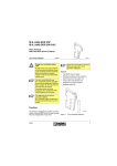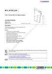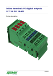
1
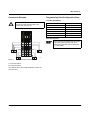
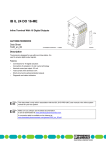
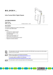
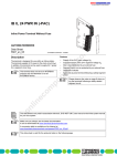
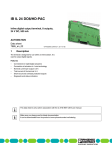
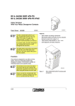
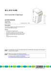
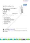
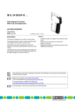
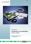
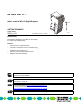
IB IL 24 DO 16 ...
Inline Terminal With 16 Digital Outputs
4 x
AUTOMATIONWORX
Data Sheet
5559_en_04
© PHOENIX CONTACT - 01/2007
5 5 5 9 B 0 0 6
Description
The terminal is designed for use within an Inline station.
It is used to output digital signals.
Features
–
–
–
–
–
–
Connections for 16 digital actuators
Connection of actuators in 2 and 3-wire technology
Nominal current per output: 0.5 A
Total current of the terminal: 8 A
Short-circuit and overload protected outputs
Diagnostic and status indicators
This data sheet is only valid in association with the IB IL SYS PRO UM E user manual or the Inline system
manual for your bus system.
Please note that the numbering of the terminal points differs with regard to the different connector versions
(see Figure 2 on page 6).
Make sure you always use the latest documentation.
It can be downloaded at www.download.phoenixcontact.com.
A conversion table is available on the Internet at
www.download.phoenixcontact.com/general/7000_en_00.pdf.
This data sheet is valid for all products listed on the following page:
IB IL 24 DO 16 ...
Ordering Data
Products
Description
Type
Order No.
Pcs./Pck.
Inline Terminal with 16 digital outputs; without accessories
transmission speed of 500 kbps
IB IL 24 DO 16
2726272
1
Inline Terminal with 16 digital outputs;
complete with accessories (connectors and labeling fields);
transmission speed of 500 kbps
IB IL 24 DO 16-PAC
2861292
1
Inline Terminal with 16 digital outputs;
complete with accessories
(connectors with individual numbering and labeling fields);
transmission speed of 500 kbps
IB IL 24 DO 16-PAC/SN
2862961
1
Inline Terminal with 16 digital outputs; without accessories
transmission speed of 2 Mbps
IB IL 24 DO 16-2MBD
2855318
1
Inline Terminal with 16 digital outputs;
complete with accessories (connectors and labeling fields);
transmission speed of 2 Mbps
IB IL 24 DO 16-2MBD-PAC
2862013
1
Inline Terminal with 16 digital outputs;
complete with accessories
(connectors with individual numbering and labeling fields);
transmission speed of 2 Mbps
IB IL 24 DO 16-2MBD-PAC/SN
2878324
1
Four of the listed connectors or one connector set are needed for complete fitting of the IB IL 24 DO 16 and the IB IL 24 DO 16-2MBD
terminals.
Accessories
Description
Type
Order No.
Pcs./Pkt
Connector, without colored identification,
for digital 4 or 16-channel Inline terminals
IB IL SCN-12
2726340
10
Connector, colored identification,
for digital 4, or 16-channel Inline terminals
IB IL SCN-12-OCP
2727624
10
Connector set with 48 spring-cage connections (green, w/o color print)
IB IL DI/DO 16-PLSET
2860976
1
Connector set with 48 spring-cage connections (green,with color print)
IB IL DO 16-PLSET/OCP
2860992
1
Description
Type
Order No.
Pcs./Pck.
"Automation Terminals of the Inline Product Range" user manual
IL SYS INST UM E
2698737
1
"Configuring and Installing the INTERBUS Inline Product Range"
user manual
IB IL SYS PRO UM E
2743048
1
Documentation
Technical Data
General Data
Housing dimensions (width x height x depth)
48.8 mm x 120 mm x 71.5 mm
Weight
130 g (without conncetor), 152 g (with connector)
Operating mode
Process data mode with 1 word
Connection method for actuators
2 and 3-wire technology
Ambient temperature (operation)
-25°C to +55°C
Ambient temperature (storage/transport)
-25°C to +85°C
Permissible humidity (operation/storage/transport)
10% to 95%, according to DIN EN 61131-2
Permissible air pressure (operation/storage/transport)
70 kPa to 106 kPa (up to 3000 m above sea level)
Degree of protection
IP20 according to IEC 60529
Protection class
Class according to VDE 0106, IEC 60539
5559_en_04
PHOENIX CONTACT
2
IB IL 24 DO 16 ...
General Data (Continued)
Connection data for Inline connector
Connection method
Spring-cage terminals
Conductor cross section
0.2 mm2 to 1.5 mm2 (solid or stranded), 24 - 16 AWG
Interface
Local bus
Through data routing
Transmission Speed
IB IL 24 DO 16; IB IL 24 DO 16-PAC; IB IL 24 DO 16-PAC/SN
500 kbps
IB IL 24 DO 16-2MBD; IB IL 24 DO 16-2MBD-PAC;
IB IL 24 DO 16-2MBD-PAC/SN
2 Mbps
Power Consumption
500 kbps
Communications power
7.5 V DC
7.5 V DC
Current consumption at UL
90 mA, maximum
105 mA, maximum
2 Mbps
Power consumption at UL
0.675 W, maximum
0.79 W, maximum
Segment supply voltage US
24 V DC (nominal value)
24 V DC (nominal value)
Nominal current consumption at US
8 A (16 x 0.5 A), maximum
8 A (16 x 0.5 A), maximum
Supply of the Module Electronics and I/O Through Bus Coupler/Power Terminal
Connection method
Through potential routing
Digital Outputs
Number
16
Nominal output voltage UOUT
24 V DC
Differential voltage for Inom
≤1V
Nominal current Inom per channel
0.5 A
Tolerance of the nominal current
+10%
Total current
8A
Protection
Short circuit; overload
Channels are thermally coupled in groups of four, i.e., an error in one channel can affect the other channels.
Nominal load
Ohmic
48 Ω/12 W
Lamp
12 W
Inductive
12 VA (1.2 H, 50 Ω)
Signal delay upon power up of:
Nominal ohmic load
500 μs, typical
Nominal lamp load
100 ms, typical (with switching frequencies up to 8 Hz; above this frequency
the lamp load responds like an ohmic load)
Nominal inductive load
100 ms (1.2 H, 50 Ω), typical
Signal delay upon power down of:
Nominal ohmic load
1 ms, typical
Nominal lamp load
1 ms, typical
Nominal inductive load
50 ms (1.2 H, 50 Ω), typical
Switching frequency with:
Nominal ohmic load
300 Hz, maximum
This switching frequency is limited by the selected data rate, the number of bus devices, the bus structure, the software, and the control
or computer system used.
Nominal lamp load
5559_en_04
8 Hz, maximum
PHOENIX CONTACT
3
IB IL 24 DO 16 ...
Digital Outputs (Continued)
This switching frequency is limited by the selected data rate, the number of bus devices, the bus structure, the software, and the control
or computer system used.
0.5 Hz (1.2 H, 50 Ω), maximum
Nominal inductive load
Overload response
Auto restart
Response time with ohmic overload (12 Ω)
3 s, approximately
Restart frequency with ohmic overload
400 Hz, approximately
Restart frequency with lamp overload
400 Hz, approximately
Response with inductive overload
Output may be damaged
Response time in the event of a short circuit
3 s, approximately
Reverse voltage protection against short pulses
Protected against reverse voltages
Resistance to permanently applied reverse voltages
Protected against reverse voltages,
permissible current 2 A, maximum
Validity of output data after connecting the 24 V supply voltage (power up)
5 ms, typical
Response upon power down
The output follows the supply voltage without delay.
Limitation of the voltage induced on circuit interruption
-15 V ≤ Udemag ≤ -45.8 V
(Udemag = demagnetization voltage)
Single maximum energy in free running
400 mJ, maximum
Protective circuit type
Integrated 45 V Zener diode in the output chip
Overcurrent circuit
0.7 A, minimum
Output current when switched off
300 μA, maximum
Output voltage when switched off
2 V, maximum
Output current with ground connection interrupt
25 mA, maximum
Switching power with ground connection interrupt
100 mW at 1 kΩ load resistance, typical
Inrush current with lamp load
1.5 A for 20 ms, maximum
Output Characteristic Curve When Switched On (Typical) (500 kbps and 2 Mbps)
Output Current (A)
Output Voltage Difference (V)
0
0
0.1
0.04
0.2
0.08
0.3
0.12
0.4
0.16
0.5
0.20
Power Dissipation
500 kbps
2 Mbps
Formula to Calculate the Power Dissipation of the Electronics
n
PTOT = 0.19 W + S (0.10 W + ILi2 x 0.4 W)
i=1
n
PTOT = 0.40 W + S (0.10 W + ILi2 x 0.4 W)
i=1
Where
PTOT
Total power dissipation in the terminal
i
index
n
Number of set outputs (n = 1 to 16)
ILi
Load current of output i
Power Dissipation of the Housing PHOU (500 kbps and 2 Mbps)
2.7 W, maximum (within the permissible operating temperature)
5559_en_04
PHOENIX CONTACT
4
IB IL 24 DO 16 ...
Limitation of Simultaneity, Derating (500 kbps and 2 Mbps)
Maximum Load Current at 100%
Ambient Temperature TA
Simultaneity
Maximum Load Current at 75%
Simultaneity
-25°C ≤ TA < +40°C
0.50
0.50
+40°C ≤ TA < +45°C
0.45
0.50
+45°C ≤ TA < +50°C
0.40
0.50
+50°C ≤ TA < +55°C
0.35
0.50
Safety Equipment
Overload/short circuit in the segment circuit
Electronic; with four 4-channel drivers
Surge voltage
Protective elements of the power terminal
Protection up to 33 V DC
Polarity reversal of the supply voltage
Protective elements of the power terminal
The supply voltage must be protected. The power supply unit should be able
to supply four times (400%) the nominal current of the fuse.
Reverse voltage
Integrated protection against reverse voltages
Electrical Isolation/Isolation of the Voltage Areas
To provide electrical isolation between the logic level and the I/O area it is necessary to supply the station bus coupler and the digital
output terminal described here via the bus coupler or a power terminal from separate power supply units. Interconnection of the power
supply units in the 24 V area is not permitted. (See also application description.)
Common Potentials
The 24 V main voltage, 24 V segment voltage, and GND have the same potential. FE is a separate potential area.
Separate Potentials in the System Consisting of Bus Coupler/Power Terminal and I/O Terminal
- Test Distance
- Test Voltage
5 V supply incoming remote bus/7.5 V supply (bus logic)
500 V AC, 50 Hz, 1 min.
5 V supply outgoing remote bus/7.5 V supply (bus logic)
500 V AC, 50 Hz, 1 min.
7.5 V supply (bus logic)/24 V supply (I/O)
500 V AC, 50 Hz, 1 min.
24 V supply (I/O)/functional earth ground
500 V AC, 50 Hz, 1 min.
Error Messages to the Higher-Level Control or Computer System
Short circuit/overload of an output
Yes
An error message is generated when an output is short circuited and switched on. In addition, the diagnostic LED (D) flashes on the terminal at 2 Hz (medium) under these conditions.
Falling below or exceeding the operating voltage
No
Approvals
For the latest approvals, please visit www.download.phoenixcontact.com.
5559_en_04
PHOENIX CONTACT
5
IB IL 24 DO 16 ...
Local Diagnostic and Status Indicators
and Terminal Point Assignment
D
1
1
1
2
2
3
4
Des.
D
1, 2,
3, 4
1
2
3
Local Diagnostic and Status Indicators
Color Meaning
Green Diagnostics
Yellow Status indicators of the outputs
2
3
3
4
4
Function Identification
4
D O 1 6
Pink
2 Mbps: White stripe in the vicinity of the D LED
Terminal Point Assignment for Each Connector
Terminal Point Assignment
5 5 5 9 C 0 0 2
Figure 1
A
Signal output (OUT)
x.2
Ground contact (GND)
for 2 and 3-wire termination
x.3
FE connection
for 3-wire termination
x.4
Signal output (OUT)
x.5
Ground contact (GND)
for 2 and 3-wire termination
x.6
FE connection
for 3-wire termination
Diagnostic and status indicators
B
4 x
x
x.1
1
2
x
x
1 .1
1
1
2 .1
1 .1
1
1 .2
2
2
2 .2
1 .2
2
1 .3
3
3
2 .3
1 .3
3
1 .4
4
4
2 .4
1 .4
4
1 .5
5
1 .6
6
1
2
1
2
1
2
1
2
1 .1
2 .1
3 .1
4 .1
5 .1
6 .1
7 .1
8 .1
1 .2
5
5
2 .5
1 .6
6
6
2 .6
3 .2
4 .2
1 .3
2 .3
3 .3
4 .3
2 .4
3 .4
1 .6
2 .6
3 .6
6 6
3
8 .3
4
8 .4
5
8 .5
6
8 .6
8 .3
7 .4
8 .4
6 .5
7 .5
8 .5
5 5
5 .6
6 6
8 .2
4 4
5 .5
4 .6
7 .3
6 .4
5 5
5 5
2
8 .2
3 3
5 .4
4 .5
7 .2
6 .3
4 4
3 .5
x
8 .1
2 2
5 .3
4 .4
4 4
2 .5
6 .2
3 3
3 3
1 .4
5 .2
2 2
2 2
1 .5
1 .5
2 .2
1
1 1
1 1
1 1
6 .6
7 .6
6 6
8 .6
5 5 5 9 B 0 0 7
Figure 2
A
B
Terminal point numbering when using
individual connectors (A) and when using a
connector set (B)
Using the IB IL 24 DO 16-PAC/SN and IB IL 24 DO 16-2MBD-PAC/SN with the provided connectors
Using individual connectors (IB IL SCN-12 or IB IL SCN-12-OCP)
Using the IB IL 24 DO 16-PAC and IB IL 24 DO 16-2MBD-PAC with the original connector set
Using the IB IL DO 16-PLSET/OCP or IB IL DI/DO 16-PLSET connector sets
5559_en_04
PHOENIX CONTACT
6
IB IL 24 DO 16 ...
Internal Circuit Diagram
L o c a l b u s
O P C
U
L
6
4
2
+ 2 4 V (U
+ 2 4 V (U
2
2
)
S
M
2
8
)
5 5 5 9 B 0 0 3
Figure 3
Internal wiring of the terminal points
Key:
OPC
Protocol chip (bus logic
including voltage conditioning)
LED
Optocoupler
Transistor
Digital output
Electrically isolated area
Other symbols used are explained in the
IB IL SYS PRO UM E user manual or the
system manual for your bus system.
5559_en_04
PHOENIX CONTACT
7
IB IL 24 DO 16 ...
Connection Example
Programming Data/Configuration Data
Local Bus (INTERBUS)
When connecting the actuators observe the
assignment of the terminal points to the
process data (see page 9).
1
1
D
2
1
1
2
3
1
2
3
4
4
3
2
2
3
4
3
4
ID code
BDhex (189dec)
Length code
01hex
Process data channel
16 bits
Input address area
0 bytes
Output address area
2 bytes
Parameter channel (PCP)
0 bytes
Register length (bus)
2 bytes
4
DO16
Other Bus Systems
1
1
2
1
2
1
2
11
11
11
1
2
22
22
22
2
3
33
33
33
3
4
44
44
44
4
5
55
55
55
5
6
66
66
66
6
For the programming data/configuration data
of other bus systems, please refer to the
corresponding electronic device data sheet
(e.g., GSD, EDS).
OUT14
1
Figure 4
OUT16
A
OUT3
OUT1
A
2
A
B
7375A004
Typical actuator connection
A: 3-wire termination
B: 2-wire termination
The numbers above the module illustration indicate the
connector slots.
5559_en_04
PHOENIX CONTACT
8
IB IL 24 DO 16 ...
Process Data
Assignment of the Terminal Points to the OUT Process Data
Please refer to the data sheet DB GB IBS SYS ADDRESS, Order No. 9000990, for the assignment of the
shown (byte.bit) view to your INTERBUS control or computer system.
For the assignment of the illustrated (byte.bit) view to control systems of other bus systems, please refer to the
AH IB IL 24 DI/DO 16 ADDRESS document, Order No. 9014124.
The following table applies to the IB IL 24 DO 16-PAC and the IB IL 24 DO 16-2MBD-PAC terminals with the
original connector set and when using the IB IL DI/DO 16-PLSET and IB IL DO 16-PLSET/OCP connector sets
(see also Figure 2 on page 6, detail B).
(Byte.bit) view
Byte
Assignment
Slot
Byte 0
Bit
7
6
5
4
3
Byte 1
2
2
1
0
7
6
1
5
4
3
2
4
1
0
3
Terminal point
(signal)
4.4 3.4 4.1 3.1 2.4 1.4 2.1 1.1 8.4 7.4 8.1 7.1 6.4 5.4 6.1 5.1
Terminal point
(GND)
4.5 3.5 4.2 3.2 2.5 1.5 2.2 1.2 8.5 7.5 8.2 7.2 6.5 5.5 6.2 5.2
Terminal point (FE)
4.6 3.6 4.3 3.3 2.6 1.6 2.3 1.3 8.6 7.6 8.3 7.3 6.6 5.6 6.3 5.3
Status indicator Slot
2
LED
4
3
1
2
1
4
3
4
2
1
4
3
3
2
1
4
3
2
1
The following table applies to the IB IL 24 DO 16-PAC/SN terminal with the original connector set and when
using the IB IL SCN-12 or IB IL SCN-12-OCP connectors (see also Figure 2 on page 6, detail A).
(Byte.bit) view
Byte
Assignment
Slot
Byte 0
Bit
7
6
5
4
3
Byte 1
2
4
1
0
7
6
3
5
4
3
2
2
1
0
1
Terminal point
(signal)
2.4 1.4 2.1 1.1 2.4 1.4 2.1 1.1 2.4 1.4 2.1 1.1 2.4 1.4 2.1 1.1
Terminal point
(GND)
2.5 1.5 2.2 1.2 2.5 1.5 2.2 1.2 2.5 1.5 2.2 1.2 2.5 1.5 2.2 1.2
Terminal point (FE)
2.6 1.6 2.3 1.3 2.6 1.6 2.3 1.3 2.6 1.6 2.3 1.3 2.6 1.6 2.3 1.3
Status indicator Slot
LED
4
4
3
3
2
1
4
3
2
2
1
4
3
1
2
1
4
3
2
1
© PHOENIX CONTACT 01/2007
5559_en_04
PHOENIX CONTACT GmbH & Co. KG • 32823 Blomberg • Germany
Phone: +49-(0) 5235-3-00 • Fax: +49-(0) 5235-3-4 12 00
www.phoenixcontact.com
9