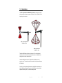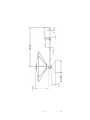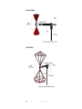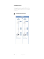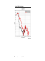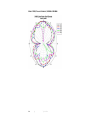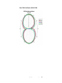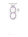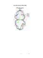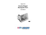
1
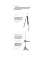
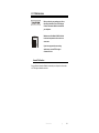
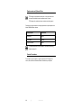
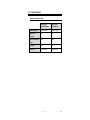
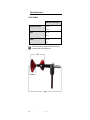
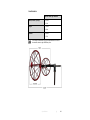
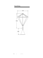
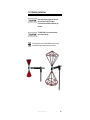
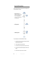
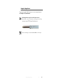
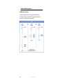
Model 3180B Mini-Bicon Antenna User Manual Model 3180B with conical elements Model 3180B with cage elements ETS-Lindgren L.P. reserves the right to make changes to any product described herein in order to improve function, design, or for any other reason. Nothing contained herein shall constitute ETS-Lindgren L.P. assuming any liability whatsoever arising out of the application or use of any product or circuit described herein. ETS-Lindgren L.P. does not convey any license under its patent rights or the rights of others. © Copyright 2012 by ETS-Lindgren L.P. All Rights Reserved. No part of this document may be copied by any means without written permission from ETS-Lindgren L.P. Trademarks used in this document: The ETS-Lindgren logo is a trademark of ETS-Lindgren L.P. Revision Record | MANUAL,MODEL 3180B | Part #399331, Rev. A ii Revision Description Date A Initial Release January, 2012 | Table of Contents Notes, Cautions, and Warnings ................................................ v 1.0 Introduction .......................................................................... 7 Tripod Options ............................................................................................ 9 ETS-Lindgren Product Information Bulletin ............................................... 10 2.0 Maintenance ....................................................................... 11 Annual Calibration .................................................................................... 11 Replacement and Optional Parts .............................................................. 12 Service Procedures .................................................................................. 12 3.0 Specifications ..................................................................... 13 Electrical Specifications ............................................................................ 13 Physical Specifications ............................................................................. 14 Conical Elements .............................................................................. 14 Cage Elements ................................................................................. 15 Dimensional Drawings .............................................................................. 16 4.0 Assembly Instructions ...................................................... 19 Parts to Assemble..................................................................................... 19 Conical Elements .............................................................................. 20 Cage Elements ................................................................................. 20 Steps to Assemble .................................................................................... 21 5.0 Mounting Instructions ....................................................... 23 Using Included Mounting Adapters ........................................................... 24 Using the Stinger Mount ........................................................................... 25 Additional Mounting Options ..................................................................... 26 4-TR Mounting Options ..................................................................... 26 7-TR and Mast Mounting Options...................................................... 27 2x2 Boom Mounting Options ............................................................. 28 6.0 Application ......................................................................... 29 7.0 Typical Data ........................................................................ 31 Typical Gain and Antenna Factor—Both Elements ................................... 31 Typical VSWR—Both Elements ................................................................ 32 Typical Radiation Patterns ........................................................................ 33 | iii Model 3180B, Conical Elements, 400 MHz–900 MHz ....................... 33 Model 3180B, Conical Elements, 1000 MHz–3000 MHz ................... 34 Model 3180B, Cage Elements, 40 MHz–100 MHz............................. 35 Model 3180B, Cage Elements, 200 MHz–600 MHz ........................... 36 Model 3180B, Cage Elements, 700 MHz–1000 MHz ......................... 37 Appendix A: Warranty ............................................................. 39 iv | Notes, Cautions, and Warnings Note: Denotes helpful information intended to provide tips for better use of the product. Caution: Denotes a hazard. Failure to follow instructions could result in minor personal injury and/or property damage. Included text gives proper procedures. Warning: Denotes a hazard. Failure to follow instructions could result in SEVERE personal injury and/or property damage. Included text gives proper procedures. See the ETS-Lindgren Product Information Bulletin for safety, regulatory, and other product marking information. | v This page intentionally left blank. vi | 1.0 Introduction The ETS-Lindgren Model 3180B Mini-Bicon Antenna is designed for optimal performance across a frequency range of 30 MHz to 1 GHz or 30 MHz to 3 GHz, depending on the elements: With conical elements: 30 MHz to 3 GHz With cage elements: 30 MHz to 1 GHz The Model 3180B ships with both sets of elements. The uniquely-designed elements provide an omni-directional pattern without the main radiation beam splitting into two lobes in the elevation cut. The Model 3180B is ideal for the Free Space NSA (FSNSA) test for fully anechoic rooms. The small size allows for harmonic monitoring when testing per IEC 61000-4-3. In addition to covering the traditional frequency range EMC measurements, the Model 3180B covers all the VHF and part of the UHF bands, making it ideal for spectrum monitoring of FM, TV, and some cellular phones. Introduction | 7 The Model 3180B is designed to have a radiation pattern that is omni-directional in the H-plane and maintains a single lobe in the E-plane across the range. The elements have been optimized to avoid splitting of the main radiation beam in the elevation cut. The Model 3180B includes a stinger mount and standard mounting hardware. For the variety of mounting options available for the Model 3180B, see Mounting Instructions on page 23. 8 | Introduction Tripod Options ETS-Lindgren offers the following nonmetallic, non-reflective tripods for use at both indoor and outdoor EMC test sites. 4-TR Tripod—Constructed of linen phenolic and delrin, designed with an adjustable center post for precise height adjustments. Maximum height is 2.0 m (80.0 in), and minimum height is 94 cm (37.0 in). This tripod can support up to an 11.8 kg (26.0 lb) load. 7-TR Tripod—Constructed of PVC and fiberglass components, providing increased stability for physically large antennas. The unique design allows for quick assembly, disassembly, and convenient storage. Allows several different configurations, including options for manual or pneumatic polarization. Quick height adjustment and locking wheels provide ease of use during testing. Maximum height is 2.17 m (85.8 in), with a minimum height of 0.8 m (31.8 in). This tripod can support a 13.5 kg (30 lb) load. Introduction | 9 ETS-Lindgren Product Information Bulletin See the ETS-Lindgren Product Information Bulletin included with your shipment for the following: 10 Warranty information Safety, regulatory, and other product marking information Steps to receive your shipment Steps to return a component for service ETS-Lindgren calibration service ETS-Lindgren contact information | Introduction 2.0 Maintenance Before performing any maintenance, follow the safety information in the ETS-Lindgren Product Information Bulletin included with your shipment. WARRANTY Maintenance of the Model 3180B is limited to external components such as cables or connectors. If you have any questions concerning maintenance, contact ETS-Lindgren Customer Service. Annual Calibration See the Product Information Bulletin included with your shipment for information on ETS-Lindgren calibration services. Maintenance | 11 Replacement and Optional Parts ETS-Lindgren may substitute a similar part or new part number with the same functionality for another part/part number. Contact ETS-Lindgren for questions about part numbers and ordering parts. Following are the part numbers for ordering replacement or optional parts for the Model 3180B Mini-Bicon Antenna. Part Description Part Number Clamp Block 102108 Support Base 101942B Support Rod White 100733 For additional/optional mounting hardware, see Additional Mounting Options on page 23. Service Procedures For the steps to return a system or system component to ETS-Lindgren for service, see the Product Information Bulletin included with your shipment. 12 | Maintenance 3.0 Specifications Electrical Specifications Model 3180B, Conical Elements Model 3180B, Cage Elements Frequency Range: 30 MHz–3 GHz 30 MHz–1 GHz VSWR Ratio (Average): ~5:1 ~5:1 Maximum Continuous Power: 50 W 200 W Impedance: 50 Ω 50 Ω Connector: Type N female Type N female Specifications | 13 Physical Specifications CONICAL ELEMENTS Model 3180B, Conical Elements Width (Element, tip-to-tip): 30.0 cm 11.8 in Length: 60.5 cm 23.8 in Diameter: 16.5 cm 6.5 in ETS-Lindgren recommends using a 6 dB pad attached to the end of the antenna; otherwise, high VSWR may occur. 14 | Specifications CAGE ELEMENTS Model 3180B, Cage Elements Width (Element, tip-to-tip): 66.3 cm 26.1 in Length: 72.2 cm 28.4 in Diameter: 40.0 cm 15.7 in ETS-Lindgren recommends using a 6 dB pad attached to the end of the antenna; otherwise, high VSWR may occur. Specifications | 15 Dimensional Drawings 16 | Specifications Specifications | 17 This page intentionally left blank. 18 | Specifications 4.0 Assembly Instructions Before connecting any components, follow the safety information in the ETS-Lindgren Product Information Bulletin included with your shipment. Parts to Assemble The Model 3180B Mini-Bicon Antenna is shipped unassembled, and includes these parts: Balun–includes attached stinger mount Belleville washer (2) Clamp block Element (2) Support rod and base Assembly Instructions | 19 CONICAL ELEMENTS CAGE ELEMENTS 20 | Assembly Instructions Steps to Assemble 1. Slide a belleville washer onto the threaded screw end of one of the elements. 2. Line up the screw threads with the receptacle hole on the balun and turn the element until it is firmly secured in the balun. Do not cross thread this connection or permanent damage to the joint could occur. 3. Repeat step 1 and step 2 using the remaining washer and element. Assembly Instructions | 21 This page intentionally left blank. 22 | Assembly Instructions 5.0 Mounting Instructions Before connecting any components, follow the safety information in the ETS-Lindgren Product Information Bulletin included with your shipment. The Model 3180B is a precision measurement device. Handle with care. The following photos show the Model 3180B mounted onto a tripod with clamp block; support base and support rod not shown. Mounting Instructions | 23 Using Included Mounting Adapters The Model 3180B Mini-Bicon Antenna ships with these mounting adapters, used to mount the antenna to a 4-TR tripod: 102108 Clamp Block—Uses standard 7/8–14 threads and comes with a 1/4–20 thread adapter for mounting to an ETS-Lindgren tripod or most other tripods. 100733 Support Rod 101942B Support Base To use these adapters to mount the Model 3180B to a 4-TR tripod: 24 1. Assemble the clamp block, support base, and support rod, and attach the support base to the 4-TR tripod. 2. Unscrew the clamp block latch and open the top. 3. Insert the balun into the clamp block and close the top over the balun. 4. Move the latch to the closed position and tighten so the balun is held securely. 5. Attach the cable to the output connector on the antenna. | Mounting Instructions Using the Stinger Mount The stinger on the Model 3180B enables you to mount to antenna directly to an ETS-Lindgren 7-TR Tripod Positioner. Additional hardware is required to use the stinger to mount the Model 3180B to a mast. For information on ordering optional mounting hardware, contact the ETS-Lindgren Sales Department. Do not use the stinger to mount the Model 3180B onto a 4-TR tripod. Mounting Instructions | 25 Additional Mounting Options 4-TR MOUNTING OPTIONS Following are additional options for mounting the Model 3180B onto an ETS-Lindgren 4-TR tripod. Contact the ETS-Lindgren Sales Department for information on ordering optional mounting hardware. 26 | Mounting Instructions 7-TR AND M AST MOUNTING OPTIONS The stinger on the Model 3180B enables you to mount to antenna directly to an ETS-Lindgren 7-TR Tripod Positioner. Following are additional options for mounting the Model 3180B onto an ETS-Lindgren 7-TR Tripod Positioner. Contact the ETS-Lindgren Sales Department for information on ordering optional mounting hardware. Mast refers to 2070 Series, 2075, and 2175 Antenna Towers. 7-TR refers to 109042, 108983, and 108507 booms: 109042 boom—Straight boom; for general antenna mounting on a 7-TR 108983 boom—Offset boom; for general antenna mounting on a 7-TR with pneumatic or manual polarization; can also be used to mount stinger-type antennas 108507 boom—For Model 3106 Series antennas only; when changing polarization, maintains centerline rotation. Mounting Instructions | 27 2X2 BOOM MOUNTING OPTIONS Following are additional options for mounting the Model 3180B onto a 2x2 boom. Contact the ETS-Lindgren Sales Department for information on ordering optional mounting hardware. 2x2 boom refers to a typical 2-inch by 2-inch boom. 28 | Mounting Instructions 6.0 Application The Model 3180B Mini-Bicon Antenna is ideally suited for swept site attenuation measurements per ANSI and FCC specifications. The Model 3180B can be used for horizontal and vertical site attenuation measurements. A 20 dB pre-amplifier is recommended in line with the receive antenna to minimize the required transmitted power and to reduce the possibility of saturation of the transmitting antenna. The maximum continuous input power for the Model 3180B is 50 W when using the conical elements (because of the higher VSWR at the lower end of the range) and 200W when using the cage elements. Each antenna is calibrated during manufacturing. The results of the calibration are tabulated as gain and antenna factor vs. frequency for use in Specification Compliance Testing. Typical data for the Model 3180B is provided in the next section. The Model 3180B is also ideal to measure the amplifier harmonics during immunity testing per IEC61000-4-3. The antenna is placed at the location of the immunity plane and the output is connected to a spectrum analyzer. The rest of the test set up is left exactly as-is during the normal immunity test. In this way the level of the harmonics measured take into account the antenna, chamber, and amplifier. Application | 29 This page intentionally left blank. 30 | Application 7.0 Typical Data Typical Gain and Antenna Factor—Both Elements Typical Data | 31 Typical VSWR—Both Elements 32 | Typical Data Typical Radiation Patterns MODEL 3180B, CONICAL ELEMENTS, 400 MHZ–900 MHZ Typical Data | 33 MODEL 3180B, CONICAL ELEMENTS, 1000 MHZ–3000 MHZ 34 | Typical Data MODEL 3180B, CAGE ELEMENTS, 40 MHZ–100 MHZ Typical Data | 35 MODEL 3180B, CAGE ELEMENTS, 200 MHZ–600 MHZ 36 | Typical Data MODEL 3180B, CAGE ELEMENTS, 700 MHZ–1000 MHZ Typical Data | 37 This page intentionally left blank. 38 | Typical Data Appendix A: Warranty See the Product Information Bulletin included with your shipment for the complete ETS-Lindgren warranty for your Model 3180B Mini-Bicon Antenna. DURATION OF WARRANTIES FOR MODEL 3180B All product warranties, except the warranty of title, and all remedies for warranty failures are limited to two years. Product Warranted Duration of Warranty Period Model 3180B Mini-Bicon Antenna 2 Years Warranty | 39