1
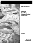
Migration Guide
Migrating PanelView Standard Applications
Important User Information
Solid-state equipment has operational characteristics differing from those of electromechanical equipment. Safety
Guidelines for the Application, Installation and Maintenance of Solid State Controls (publication SGI-1.1 available from
your local Rockwell Automation sales office or online at http://www.rockwellautomation.com/literature/) describes some
important differences between solid-state equipment and hard-wired electromechanical devices. Because of this difference,
and also because of the wide variety of uses for solid-state equipment, all persons responsible for applying this equipment
must satisfy themselves that each intended application of this equipment is acceptable.
In no event will Rockwell Automation, Inc. be responsible or liable for indirect or consequential damages resulting from
the use or application of this equipment.
The examples and diagrams in this manual are included solely for illustrative purposes. Because of the many variables and
requirements associated with any particular installation, Rockwell Automation, Inc. cannot assume responsibility or
liability for actual use based on the examples and diagrams.
No patent liability is assumed by Rockwell Automation, Inc. with respect to use of information, circuits, equipment, or
software described in this manual.
Reproduction of the contents of this manual, in whole or in part, without written permission of Rockwell Automation,
Inc., is prohibited.
Throughout this manual, when necessary, we use notes to make you aware of safety considerations.
WARNING: Identifies information about practices or circumstances that can cause an explosion in a hazardous
environment, which may lead to personal injury or death, property damage, or economic loss.
ATTENTION: Identifies information about practices or circumstances that can lead to personal injury or death,
property damage, or economic loss. Attentions help you identify a hazard, avoid a hazard, and recognize the
consequence
SHOCK HAZARD: Labels may be on or inside the equipment, for example, a drive or motor, to alert people that
dangerous voltage may be present.
BURN HAZARD: Labels may be on or inside the equipment, for example, a drive or motor, to alert people that
surfaces may reach dangerous temperatures.
IMPORTANT
Identifies information that is critical for successful application and understanding of the product.
Allen-Bradley, DH+, PanelView Standard, PanelView Plus, FactoryTalk View Machine Edition, FactoryTalk View Studio, RSLinx, PanelBuilder32, SLC, PLC-5, ControlLogix, Rockwell Software, Rockwell Automation, and
TechConnect are trademarks of Rockwell Automation, Inc.
Trademarks not belonging to Rockwell Automation are property of their respective companies.
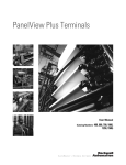
Where to Start
We Can Get You from Here...
PanelView Standard Terminal
SLC 500 Controller
PLC-5 Controller
ControlLogix Controller
...to Here
PanelView Plus Terminals
SLC 500 Controller
PLC-5 Controller
Rockwell Automation Publication 2711P-AP001A-EN-P - February 2011
ControlLogix Controller
3
Where to Start
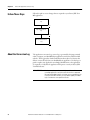
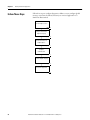
Follow this path to migrate your PanelView Standard terminal and application to
the PanelView Plus terminal platform.
Chapter 1
Things to Know Before You
Migrate
Chapter 2
Select a Terminal
Replacement
Chapter 3
Import Your Application
Chapter 4
Review the Application
Conversion Log
Chapter 5
Review Object Mapping
Chapter 6
Review Unsupported
Features
Chapter 7
Qualify the Runtime
Application
Chapter 8
Create the Runtime
Application
Chapter 9
Optimize Runtime
Performance
4
Before updating the migrated application,
review the conversion log details and the
remaining chapters. If you determine that
the conversion operation would not be
feasible, you can use the conversion
services provided by Rockwell
Automation. For more information, see
Conversion Services, publication
GMSC10-PP009
Appendix A
Advanced Object Editing
Rockwell Automation Publication 2711P-AP001A-EN-P - February 2011
Table of Contents
Preface
Introduction. . . . . . . . . . . . . . . . . . . . . . . . . . . . . . . . . . . . . . . . . . . . . . . . . . . . . . . 9
Audience . . . . . . . . . . . . . . . . . . . . . . . . . . . . . . . . . . . . . . . . . . . . . . . . . . . . . . . . 10
Required Software. . . . . . . . . . . . . . . . . . . . . . . . . . . . . . . . . . . . . . . . . . . . . . . . 10
Migration Services. . . . . . . . . . . . . . . . . . . . . . . . . . . . . . . . . . . . . . . . . . . . . . . . 10
Additional Resources . . . . . . . . . . . . . . . . . . . . . . . . . . . . . . . . . . . . . . . . . . . . . 11
Chapter 1
Things to Know Before You
Migrate
Introduction. . . . . . . . . . . . . . . . . . . . . . . . . . . . . . . . . . . . . . . . . . . . . . . . . . . . .
External Fonts . . . . . . . . . . . . . . . . . . . . . . . . . . . . . . . . . . . . . . . . . . . . . . . . . . .
Retain Last States on Startup . . . . . . . . . . . . . . . . . . . . . . . . . . . . . . . . . . . . . .
Unsupported Characters in Tag Names and Addresses . . . . . . . . . . . . . .
Bit Array Tags . . . . . . . . . . . . . . . . . . . . . . . . . . . . . . . . . . . . . . . . . . . . . . . . . . .
String Tags . . . . . . . . . . . . . . . . . . . . . . . . . . . . . . . . . . . . . . . . . . . . . . . . . . . . . .
Alarm Trigger Tags. . . . . . . . . . . . . . . . . . . . . . . . . . . . . . . . . . . . . . . . . . . . . . .
Bit Position Triggers . . . . . . . . . . . . . . . . . . . . . . . . . . . . . . . . . . . . . . . . . .
Least Significant Bit Triggers . . . . . . . . . . . . . . . . . . . . . . . . . . . . . . . . . .
Alarm Messages . . . . . . . . . . . . . . . . . . . . . . . . . . . . . . . . . . . . . . . . . . . . . . . . . .
Tags Assigned to Message Connections . . . . . . . . . . . . . . . . . . . . . . . . . . . .
13
14
14
14
14
14
15
15
16
17
17
Chapter 2
Select a Terminal Replacement Introduction. . . . . . . . . . . . . . . . . . . . . . . . . . . . . . . . . . . . . . . . . . . . . . . . . . . . . 19
Before You Begin. . . . . . . . . . . . . . . . . . . . . . . . . . . . . . . . . . . . . . . . . . . . . . . . .
Follow These Steps . . . . . . . . . . . . . . . . . . . . . . . . . . . . . . . . . . . . . . . . . . . . . . .
Selecting a Terminal Replacement . . . . . . . . . . . . . . . . . . . . . . . . . . . . . . . . .
Reviewing Terminal Comparisons . . . . . . . . . . . . . . . . . . . . . . . . . . . . . . . . .
Function Key Comparisons . . . . . . . . . . . . . . . . . . . . . . . . . . . . . . . . . . . . . . .
Installing a PanelView Plus Terminal . . . . . . . . . . . . . . . . . . . . . . . . . . . . . .
19
19
20
21
24
24
Chapter 3
Import Your Application
Introduction. . . . . . . . . . . . . . . . . . . . . . . . . . . . . . . . . . . . . . . . . . . . . . . . . . . . .
Before You Begin. . . . . . . . . . . . . . . . . . . . . . . . . . . . . . . . . . . . . . . . . . . . . . . . .
What You Need . . . . . . . . . . . . . . . . . . . . . . . . . . . . . . . . . . . . . . . . . . . . . . . . .
Follow These Steps . . . . . . . . . . . . . . . . . . . . . . . . . . . . . . . . . . . . . . . . . . . . . . .
Import Application. . . . . . . . . . . . . . . . . . . . . . . . . . . . . . . . . . . . . . . . . . . . . . .
Post Conversion Tips. . . . . . . . . . . . . . . . . . . . . . . . . . . . . . . . . . . . . . . . . . . . .
25
25
25
26
27
30
Chapter 4
Review the Application
Conversion Log
Introduction. . . . . . . . . . . . . . . . . . . . . . . . . . . . . . . . . . . . . . . . . . . . . . . . . . . . .
Before You Begin. . . . . . . . . . . . . . . . . . . . . . . . . . . . . . . . . . . . . . . . . . . . . . . . .
What You Need . . . . . . . . . . . . . . . . . . . . . . . . . . . . . . . . . . . . . . . . . . . . . . . . .
Follow These Steps . . . . . . . . . . . . . . . . . . . . . . . . . . . . . . . . . . . . . . . . . . . . . . .
About the Conversion Log. . . . . . . . . . . . . . . . . . . . . . . . . . . . . . . . . . . . . . . .
Open the Conversion Log . . . . . . . . . . . . . . . . . . . . . . . . . . . . . . . . . . . . . . . .
Review the Conversion Log . . . . . . . . . . . . . . . . . . . . . . . . . . . . . . . . . . . . . . .
Rockwell Automation Publication 2711P-AP001A-EN-P - February 2011
31
31
31
32
32
33
34
5
Table of Contents
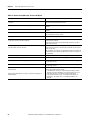
Conversion Messages You Can Ignore . . . . . . . . . . . . . . . . . . . . . . . . . .
RSLinx Messages. . . . . . . . . . . . . . . . . . . . . . . . . . . . . . . . . . . . . . . . . . . . . .
Screen and Object Conversion Messages . . . . . . . . . . . . . . . . . . . . . . . .
Tag Conversion Messages . . . . . . . . . . . . . . . . . . . . . . . . . . . . . . . . . . . . .
Alarm Conversion Messages . . . . . . . . . . . . . . . . . . . . . . . . . . . . . . . . . . .
34
35
35
37
38
Chapter 5
Review Object Mapping
Introduction . . . . . . . . . . . . . . . . . . . . . . . . . . . . . . . . . . . . . . . . . . . . . . . . . . . . .
Before You Begin . . . . . . . . . . . . . . . . . . . . . . . . . . . . . . . . . . . . . . . . . . . . . . . . .
What You Need . . . . . . . . . . . . . . . . . . . . . . . . . . . . . . . . . . . . . . . . . . . . . . . . . .
Follow These Steps . . . . . . . . . . . . . . . . . . . . . . . . . . . . . . . . . . . . . . . . . . . . . . .
Reviewing Object Mapping. . . . . . . . . . . . . . . . . . . . . . . . . . . . . . . . . . . . . . . .
Reviewing Data Type Mapping . . . . . . . . . . . . . . . . . . . . . . . . . . . . . . . . . . . .
Reviewing Mapping of Communication Networks . . . . . . . . . . . . . . . . . .
39
39
39
40
40
41
41
Chapter 6
Review Unsupported Features
Introduction . . . . . . . . . . . . . . . . . . . . . . . . . . . . . . . . . . . . . . . . . . . . . . . . . . . . .
Before You Begin . . . . . . . . . . . . . . . . . . . . . . . . . . . . . . . . . . . . . . . . . . . . . . . . .
What You Need . . . . . . . . . . . . . . . . . . . . . . . . . . . . . . . . . . . . . . . . . . . . . . . . . .
Follow These Steps . . . . . . . . . . . . . . . . . . . . . . . . . . . . . . . . . . . . . . . . . . . . . . .
Reviewing Unsupported Objects. . . . . . . . . . . . . . . . . . . . . . . . . . . . . . . . . . .
Reviewing Unsupported Tags and Controls . . . . . . . . . . . . . . . . . . . . . . . .
Reviewing Unsupported Features . . . . . . . . . . . . . . . . . . . . . . . . . . . . . . . . . .
43
43
43
44
44
44
45
Chapter 7
Qualify the Runtime Application Introduction . . . . . . . . . . . . . . . . . . . . . . . . . . . . . . . . . . . . . . . . . . . . . . . . . . . . . 47
Before You Begin . . . . . . . . . . . . . . . . . . . . . . . . . . . . . . . . . . . . . . . . . . . . . . . . .
What You Need . . . . . . . . . . . . . . . . . . . . . . . . . . . . . . . . . . . . . . . . . . . . . . . . . .
Follow These Steps . . . . . . . . . . . . . . . . . . . . . . . . . . . . . . . . . . . . . . . . . . . . . . .
Review Diagnostic Lists . . . . . . . . . . . . . . . . . . . . . . . . . . . . . . . . . . . . . . . . . . .
Configure the Runtime Diagnostic Display . . . . . . . . . . . . . . . . . . . . . . . . .
Review Error States for Graphic Objects. . . . . . . . . . . . . . . . . . . . . . . . . . . .
Configure Communication . . . . . . . . . . . . . . . . . . . . . . . . . . . . . . . . . . . . . . .
Test Run Graphic Displays . . . . . . . . . . . . . . . . . . . . . . . . . . . . . . . . . . . . . . . .
Test Run the Application . . . . . . . . . . . . . . . . . . . . . . . . . . . . . . . . . . . . . . . . .
6
Rockwell Automation Publication 2711P-AP001A-EN-P - February 2011
47
47
48
49
50
51
52
54
56
Table of Contents
Chapter 8
Create the Runtime Application Introduction. . . . . . . . . . . . . . . . . . . . . . . . . . . . . . . . . . . . . . . . . . . . . . . . . . . . . 57
Before You Begin. . . . . . . . . . . . . . . . . . . . . . . . . . . . . . . . . . . . . . . . . . . . . . . . .
What You Need . . . . . . . . . . . . . . . . . . . . . . . . . . . . . . . . . . . . . . . . . . . . . . . . .
Follow These Steps . . . . . . . . . . . . . . . . . . . . . . . . . . . . . . . . . . . . . . . . . . . . . . .
Create the Runtime Application. . . . . . . . . . . . . . . . . . . . . . . . . . . . . . . . . . .
Download the Runtime Application . . . . . . . . . . . . . . . . . . . . . . . . . . . . . . .
Download Application Using Ethernet Connection . . . . . . . . . . . . .
Download Application Using External Storage. . . . . . . . . . . . . . . . . .
Run the Application. . . . . . . . . . . . . . . . . . . . . . . . . . . . . . . . . . . . . . . . . . . . . .
57
57
58
59
60
60
64
66
Chapter 9
Optimize Runtime Performance Introduction. . . . . . . . . . . . . . . . . . . . . . . . . . . . . . . . . . . . . . . . . . . . . . . . . . . . . 67
Before You Begin. . . . . . . . . . . . . . . . . . . . . . . . . . . . . . . . . . . . . . . . . . . . . . . . .
What You Need . . . . . . . . . . . . . . . . . . . . . . . . . . . . . . . . . . . . . . . . . . . . . . . . .
Follow These Steps . . . . . . . . . . . . . . . . . . . . . . . . . . . . . . . . . . . . . . . . . . . . . . .
Benchmarking Performance. . . . . . . . . . . . . . . . . . . . . . . . . . . . . . . . . . . . . . .
Reviewing Tag Update Rate. . . . . . . . . . . . . . . . . . . . . . . . . . . . . . . . . . . . . . .
Measure Performance of Display Changes . . . . . . . . . . . . . . . . . . . . . . . . . .
Reviewing Background Updates . . . . . . . . . . . . . . . . . . . . . . . . . . . . . . . . . . .
Global Connections . . . . . . . . . . . . . . . . . . . . . . . . . . . . . . . . . . . . . . . . . .
Alarms. . . . . . . . . . . . . . . . . . . . . . . . . . . . . . . . . . . . . . . . . . . . . . . . . . . . . . .
Information Messages. . . . . . . . . . . . . . . . . . . . . . . . . . . . . . . . . . . . . . . . .
Optimize Tags for Network Performance . . . . . . . . . . . . . . . . . . . . . . . . . .
About the Tag Converter Wizard. . . . . . . . . . . . . . . . . . . . . . . . . . . . . .
Export the HMI Tag Database . . . . . . . . . . . . . . . . . . . . . . . . . . . . . . . .
Export Graphic Displays to XML File . . . . . . . . . . . . . . . . . . . . . . . . . .
Export Alarms to XML File . . . . . . . . . . . . . . . . . . . . . . . . . . . . . . . . . . .
Run the Tag Converter Wizard. . . . . . . . . . . . . . . . . . . . . . . . . . . . . . . .
Re-import the Display XML File. . . . . . . . . . . . . . . . . . . . . . . . . . . . . . .
Re-import the Alarms XML File . . . . . . . . . . . . . . . . . . . . . . . . . . . . . . .
67
67
68
68
69
70
71
71
72
73
73
74
75
77
79
81
84
87
Appendix A
Advanced Object Editing
Introduction. . . . . . . . . . . . . . . . . . . . . . . . . . . . . . . . . . . . . . . . . . . . . . . . . . . . .
Property Panel . . . . . . . . . . . . . . . . . . . . . . . . . . . . . . . . . . . . . . . . . . . . . . . . . . .
Edit Multiple Objects . . . . . . . . . . . . . . . . . . . . . . . . . . . . . . . . . . . . . . . . . . . .
Object Explorer . . . . . . . . . . . . . . . . . . . . . . . . . . . . . . . . . . . . . . . . . . . . . . . . . .
Substitute Tags . . . . . . . . . . . . . . . . . . . . . . . . . . . . . . . . . . . . . . . . . . . . . . . . . .
89
89
90
92
96
Index
Rockwell Automation Publication 2711P-AP001A-EN-P - February 2011
7
Table of Contents
8
Rockwell Automation Publication 2711P-AP001A-EN-P - February 2011
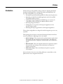
Preface
Introduction
This document provides guidelines and procedures for migrating a PanelView
Standard terminal application to the PanelView Plus terminal platform. The
procedures and guidelines cover the following:
• Selecting and optionally installing a PanelView Plus terminal replacement
• Importing your PanelView Standard application into the FactoryTalk
View Machine Edition software
• Updating the imported application and ladder logic, as necessary, for
compatibility with FactoryTalk View Machine Edition software
• Reviewing unsupported features
• Verifying the correct operation of the imported application on the
PanelView Plus terminal
• Measuring and improving performance of the migrated application
The procedures and guidelines are designed to make the migration process as easy
as possible.
The beginning of most chapters contains the following information. Read these
sections carefully before beginning work in each chapter.
• Before You Begin - This section lists the steps that must be completed and
decisions that must be made before starting the chapter. The chapters in
this quick start must be completed or reviewed in the order in which they
appear.
• What You Need - This section lists the items that are required to complete
the steps in the current chapter. This includes, but is not limited to,
hardware and software.
• Follow These Steps - This section illustrates the path or steps in the
current chapter.
Also note that the electronic version of this publication contains links to other
publications for easier navigation and reference.
Rockwell Automation Publication 2711P-AP001A-EN-P - February 2011
9
Preface
Audience
This quick start was created to assist a user familiar with Rockwell Automation
HMI products on how to convert existing PanelView Standard applications to
FactoryTalk View Machine Edition applications that run on PanelView Plus
terminals.
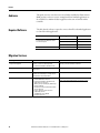
Required Software
The table lists the software required to convert a PanelView Standard application
to a PanelView Plus application.
Software
Terminal Type
Software Version
FactoryTalk View Studio, which includes:
• FactoryTalk View Machine Edition
• RSLinx Enterprise
PanelView Plus 400 or 600
4.0 or later
PanelView Plus 700 to 1500
5.1 or earlier
PanelView Plus 6 (700 to 1500)
6.0 or later
—
3.83 or earlier
PanelBuilder32
Migration Services
This migration service
Includes
For more information
Step Forward program
Provides a credit for returned product
Consult your local distributor for details
• PanelView Standard to PanelView Plus
PanelView Standard migration kits
PanelView Plus terminal and adapter plate at a
reduced price
Consult your local distributor for details
PanelView Plus starter kits
PanelView Plus terminal and associated
software at a reduced price to help you get
started with a new product family
Consult your local distributor for details
Bundled migration services
• PanelView Standard to PanelView Plus
terminal hardware conversion
• PanelView Standard to PanelView Plus
application file conversion
• Turnkey service including any ladder logic
changes required
• Delivered onsite by Rockwell Automation
service engineers
• Project supervision and conversion
engineering services
• Standardized service bundle
• Fixed price proposal
For more information on services, go to:
http://www.rockwellautomation.com/services/onsite
10
Rockwell Automation Publication 2711P-AP001A-EN-P - February 2011
Preface
Additional Resources
The table lists resources available for the PanelView Plus terminals.
Resource
Description
Cutout Adapter Kit for PanelView Plus 400 Keypad, Keypad/
Touch, and 600 Touch Terminals, Installation Instructions,
publication 2711P-IN020
Provides details on how to use the cutout adapter kit, catalog number 2711P-RAK4, to
mount a PanelView Plus 400 keypad, keypad/touch, or 600 touch terminal into the
existing panel cutout of a PanelView Standard 550 keypad and keypad/touch terminal.
Cutout Adapter Kit for PanelView Plus 600 Keypad and Keypad/
Touch Terminals, Installation Instructions, publication 2711PIN020
Provides details on how to use the cutout adapter kit, catalog number 2711P-RAK6, to
mount a PanelView Plus 600 keypad or keypad/touch terminal into the existing panel
cutout of a PanelView Standard 600 keypad or keypad/touch terminal.
Adapter Kit for PanelView Standard Terminal Cutouts
Installation Instructions, publication 2711P-IN010
Provides details on how to use the following cutout adapters to mount PanelView Plus
terminals into the panel cutouts of PanelView Standard terminals:
• Use catalog number 2711P-RAK7 to mount a PanelView Plus 700 keypad or keypad/
touch terminal into the panel cutout of a PanelView Standard 900 keypad terminal.
• Use catalog number 2711P-RAT7 to mount a PanelView Plus 700 touch terminal into
the panel cutout of a PanelView Standard 900 touch terminal.
• Use catalog number 2711P-RAK10 to mount a PanelView Plus 1000 keypad or
keypad/touch terminal into the panel cutout of a PanelView Standard 1000 keypad
terminal.
• Use catalog number 2711P-RAT10 to mount a PanelView Plus 1000 touch terminal
into the panel cutout of a PanelView Standard 1000 touch terminal.
• Use catalog number 2711P-RAK12S to mount a PanelView Plus 1250 keypad or
keypad/touch terminal into the panel cutout of a PanelView Standard 1400 keypad
terminal
• Use catalog number 2711P-RAT12S to mount a PanelView Plus 1250 touch terminal
into the panel cutout of a PanelView Standard 1400 touch terminal.
PanelView Plus 6 Terminals User Manual,
publication 2711P-UM006
Provides information on how to install, operate, configure, and troubleshoot
PanelView Plus 6 terminals (700, 1000, 1250, 1500).
PanelView Plus Terminals User Manual,
publication 2711P-UM001
Provides information on how to install, operate, configure, and troubleshoot
PanelView Plus 700, 1000, 1250, and 1500 terminals running FactoryTalk View
Machine Edition software version 5.1 or earlier.
PanelView Plus Terminals User Manual,
publication 2711PC-UM001
Provides information on how to install, operate, configure, and troubleshoot
PanelView Plus Compact 400, 600, and 1000 terminals.
Visualization Solutions Selection Guide,
publication VIEW-SG001
Provides an overview of visualization products including PanelView Plus 6 terminals.
FactoryTalk View Studio online help
Provides information and procedures for creating FactoryTalk View Machine Edition
applications and supported features.
You can view or download publications at http://www.rockwellautomation.com/
literature.
To order paper copies of technical documentation, contact your local Rockwell
Automation distributor or sales representative.
Rockwell Automation Publication 2711P-AP001A-EN-P - February 2011
11
Preface
12
Rockwell Automation Publication 2711P-AP001A-EN-P - February 2011
Chapter
1
Things to Know Before You Migrate
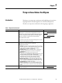
Introduction
This chapter covers important considerations and helpful things to know before
migrating a PanelView Standard application to a PanelView Plus platform.
The table covers important considerations when migrating an application.
Table 1 - Migration Considerations
Migration Consideration
Explanation
For More Information
Application reuse?
Do you need to reuse your PanelView Standard application and PLC
ladder logic? If so, you can convert your application for use with a
PanelView Plus terminal using FactoryTalk View Machine Edition (ME)
software. The application and PLC ladder logic may require updates
because some objects or features may not directly migrate to
FactoryTalk View ME software.
Refer to Reviewing Object Mapping
on page 40
Refer to Reviewing Unsupported
Features on page 45
If you want to create a new FactoryTalk View ME application instead of
reusing your current application, stop here.
Require enhanced features?
Does your application require enhanced features? If so, you can take
advantage of the advanced features offered by the
PanelView Plus 6 terminals:
• Functions: trending, data logging, alarming, information and local
messages, expressions, security, language switching, recipes, global
objects, multiversion support, faceplates, graphic libraries,
parameter files, rich graphics, and animation.
• Communication: Ethernet, ControlNet, DHPlus, and third-party
connectivity to additional protocols. Ethernet is the preferred
communication.
• Hardware: 8-wire analog resistive touchscreen, x86
1 GHz processor, 512 MB RAM and 512 MB nonvolatile memory, USB
and Secure Digital (SD) media support, modular display,
communication, and logic components. Other advantages include a
high-bright display, conformal-coated, and marine-certified
components to meet more stringent environmental conditions.
• Remote connectivity: FTP server, web server, VNC client/server,
ActiveX controls, PDF reader, and FactoryTalk ViewPoint remote
access is available on all PanelView Plus 6 terminals (700 to 1500),
catalog numbers 2711P-xxxx8, 2711P-xxxx9.
• Extended features: PanelView Plus 6 terminals with extended
features, catalog numbers 2711P-I9, include a Web browser, remote
desktop connection, Microsoft Office file viewers, and WordPad text
editor.
Terminal replacement options?
The terminal replacement for the PanelView Standard platform is the
PanelView Plus platform.
Rockwell Automation Publication 2711P-AP001A-EN-P - February 2011
Refer to Selecting a Terminal
Replacement on page 20
13
Chapter 1
Things to Know Before You Migrate
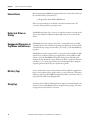
External Fonts
Before importing a PanelBuilder32 application that uses external fonts, make sure
the external font file is in this directory:
C:\Program Files\Allen-Bradley\PBEX\Fonts
If the conversion utility does not find the external font in this location, the
conversion will stop without reporting an error.
Retain Last States on
Startup
PanelBuilder32 software lets you choose to retain the last states on startup for all
objects. FactoryTalk View Machine Edition (ME) software does not have this
feature.
Unsupported Characters in
Tag Names and Addresses
PanelBuilder32 software supports semicolons (;) in tag addresses; FactoryTalk
View ME software does not. Before importing your application into FactoryTalk
View ME software, change the semicolons (;) to colons (:) in the PanelBuilder32
tag editor.
PanelBuilder32 software supports dashes (-) in tag names, FactoryTalk View ME
software does not. Before importing your application to FactoryTalk View ME
software, search the PanelBuilder32 tag editor for tag names with dashes and
duplicate the tags. Rename the tags to eliminate the dash, or replace the dash with
an underscore (_). Use the tag search function to find graphic objects using the
original tag names. Edit the objects to update the tag names.
Bit Array Tags
You can monitor bit arrays for alarm conditions in FactoryTalk View applications
but you can’t assign bit arrays to graphic objects, or write to bit arrays. This means
all bit array tags in your PanelBuilder32 application will be converted to memory
tags in the FactoryTalk View ME application.
String Tags
At runtime, FactoryTalk View ME applications support a maximum length of 82
characters. Because PanelBuilder32 protocols support longer strings, some alarm
messages may be truncated after conversion.
14
Rockwell Automation Publication 2711P-AP001A-EN-P - February 2011
Things to Know Before You Migrate
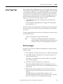
Alarm Trigger Tags
Chapter 1
Bit arrays with the Bit or LSBit trigger types are used to trigger alarm messages in
a FactoryTalk View ME application. Assigning alarm triggers to elements in a bit
array, instead of bit addresses, frees up tags in the database for other uses. When
an element of an array changes from 0 to 1, it can generate an alarm message if a
message has been set up for that bit position. With the Bit trigger type, you can
generate simultaneous alarm messages, one for each element. With the LSB
trigger type, only the lowest bit position triggers an alarm:
• In a PanelBuilder32 application, the trigger value for the bit data type
ranges from 0…31.
• In a FactoryTalk View ME application, the trigger value for the bit data
type ranges from 1…32.
The number of bits in the array depends on the data type of the tag. Integer data
types, for example, return 16 bits per element, while Bit data types return 8 bits
per element.
To trigger a digital alarm based on an array of controller bits, you must use a direct
reference and the syntax:
tagname,Larraylength (for example, [PLC5]N7:0,L5
TIP
Don’t leave a space between the tag address and the length. For
example, the address {[SLC]BlockWrite1, L8}, where BlockWrite is the
equivalent of N7:0, will not work. {[SLC]BlockWrite1,L8} will work.
Bit Position Triggers
Follow these steps in the FactoryTalk View ME application to trigger alarms by
using bit positions.
1. In the Trigger tab of the Alarm Setup editor, create a Bit type alarm trigger.
2. In the Trigger dialog box, click Browse in the Tag column and browse to
the first element of an array.
For example, in a Logix5000 controller called CLGX1, select AAlm[0].
This is an integer tag type.
3. Click OK to insert the tag address into your trigger tag.
This address {[CLGX1]AAlm[0]} will be the starting element in your
array tag. [CLGX1] is the direct reference or the RSLinx Enterprise device
shortcut name.
4. Double-click the address and append a comma and the letter L to the
address, then type the number of elements you want to include in your
array tag.
To add 64 elements to the example address, modify it to read
{[CLGX1]AAlm[0],L64]}. This syntax will return (64 x 16 =) 1024 bits.
Do not leave a space between the tag address and the length.
Rockwell Automation Publication 2711P-AP001A-EN-P - February 2011
15
Chapter 1
Things to Know Before You Migrate
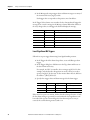
5. In the Messages tab, assign trigger values and alarm messages to as many of
the elements in the array tag as you like.
Each trigger value corresponds to a bit position, not a bit address.
In the Trigger Value column, enter a number for the element that will trigger the
message, then create the message in the Message column. When that element in
the array changes value, it will trigger the alarm and display the message.
Bit Position
Trigger Value
Message
1
1
Line 1: Conveyor has stopped
2
2
Line 1: Power failure
3
3
Line 2: Conveyor has stopped
4
4
Line 2: Power failure
...
...
...
1024
1024
Line 6: Oven door open
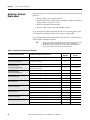
Least Significant Bit Triggers
Follow these steps to trigger alarms using Least Significant Bit positions.
1. In the Trigger tab of the Alarm Setup editor, create an LSBit type alarm
trigger.
2. In the Trigger dialog box, click Browse in the Tag column and browse to
the first element of an array.
For example, in a PLC-5 controller, select an integer tag N7:61. For this
example, only the first three bit positions are used, so there’s no need to
specify a length (L) for the array. To also monitor bits in N7:62, add L2 to
the address: ::[PLC5]N7:61,L2.
3. Specify these trigger values and alarm messages for the alarm trigger.
Bit in Array
Bit position
Trigger Value
Message
00
1
1
Motor has lost power
01
2
2
Motor has stopped
02
3
3
Overload switch has lost power
If the motor loses power at runtime, all three bit values change from 0 to 1. Only
the first alarm message is generated, because bit 00 is the least significant or the
lowest bit. If the operator acknowledges the first alarm and power is not yet
restored, the second alarm is generated, and so on.
16
Rockwell Automation Publication 2711P-AP001A-EN-P - February 2011
Things to Know Before You Migrate
Alarm Messages
Chapter 1
Both PanelBuilder32 and Machine Edition applications perform the same three
steps when an alarm is triggered.
1. Send the alarm message to the Data Tag connection.
2. Set the Notification Tag connection to 1.
3. Reset the Notification Tag connection to 0 when the Handshake tag
changes to a nonzero value.
The PanelBuilder32 application performs additional steps that are not required
by the ME application.
4. Send Null (00) to the Data Tag, overwriting the alarm message.
5. Set the Notification Tag to 1.
6. Reset the Notification Tag to 0 when the Handshake tag changes to a new
nonzero value.
The Data tag is now ready to accept a new alarm message.
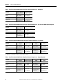
Tags Assigned to Message
Connections
Some PanelBuilder32 tags are assigned to Message connections in the converted
Machine Edition application.
This Tag in PanelBuilder32
Is Assigned to This Connection in ME
Remote Device Data tag
Message connection
Remote Device Notification tag
Message Notification connection
Remote Device Handshake tag
Message Handshake connection
Rockwell Automation Publication 2711P-AP001A-EN-P - February 2011
17
Chapter 1
Things to Know Before You Migrate
Notes:
18
Rockwell Automation Publication 2711P-AP001A-EN-P - February 2011
Chapter
2
Select a Terminal Replacement
Introduction
In this chapter, you will select and optionally install a PanelView Plus terminal
replacement for your PanelView Standard terminal.
Before You Begin
Review the migration considerations table (chapter 1).
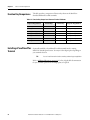
Follow These Steps
Follow these steps to select a PanelView Plus terminal as a replacement for your
PanelView Standard terminal.
Selecting a Terminal
Replacement
Page 20
Reviewing Terminal
Comparisons
Page 21
Function Key
Comparisons
Page 24
Installing a PanelView
Plus Terminal
Page 24
Rockwell Automation Publication 2711P-AP002A-EN-P - February 2011
19
Chapter 2
Select a Terminal Replacement
Selecting a Terminal
Replacement
Replacement options for the PanelView Standard terminals include the following
platforms:
• PanelView Plus 6 (700 to 1500) terminals
• PanelView Plus 700 to 1500 terminals running FactoryTalk View Machine
Edition software version 5.1 or earlier
• PanelView Plus 400 and 600 terminals
• PanelView Plus Compact 400, 600, and1000 terminals
Some of the PanelView Plus terminals fit directly into the existing panel cutouts
of the PanelView Standard terminals; others require an adapter plate.
None of the PanelView Plus terminals fit into the panel cutouts of the PanelView
Standard 300 or 300 Micro terminals.
TIP
• References to PanelView Plus 700, 1000, 1250, or 1500 terminal apply to both the
PanelView Plus 6 (700 to 1500) and PanelView Plus 700 to 1500 platforms.
• PanelView Plus Compact terminals use the same cutouts and adapter plates as
the corresponding PanelView Plus 400, 600, and 1000 models.
Table 2 - PanelView Plus Replacement Terminals
Adapter Plate
Required
Adapter Plate
Cat. No.
None(1)
—
—
PanelView Plus 400 keypad or keypad/touch
PanelView Plus 600 touch
No
—
PanelView Plus 600 keypad or keypad/touch
No
—
PanelView Plus 400 keypad or keypad/touch
PanelView Plus 600 touch
Yes
2711P-RAK4
PanelView Plus 600 keypad or keypad/touch
Yes
2711P-RAK6
PanelView Plus 700 keypad or keypad/touch
No
—
PanelView Plus 700 keypad or keypad/touch
Yes
2711P-RAK7
PanelView Plus 1000 keypad or keypad/touch
No
—
PanelView Plus 700 touch
Yes
2711P-RAT7
PanelView Plus 1000 touch
No
—
PanelView Plus 1000 keypad or keypad/touch
Yes
2711P-RAK10
PanelView Plus 1250 keypad or keypad/touch
No
—
PanelView Plus 1000 touch
Yes
2711P-RAT10
PanelView Plus 1250 touch
No
—
PanelView Plus 1250 keypad or keypad/touch
Yes
2711P-RAK12S
PanelView Plus 1500 keypad or keypad/touch
No
—
PanelView Plus 1250 touch
Yes
2711P-RAT12S
PanelView Plus 1500 touch
No
—
PanelView Standard Terminal
PanelView Plus Replacement Terminal
PanelView Standard 300 or 300 Micro
PanelView 550 or 600 touch
PanelView 550 keypad
PanelView 550 keypad/touch
PanelView 600 keypad
PanelView 600 keypad/touch
PanelView 900 keypad
PanelView 900 touch
PanelView 1000 keypad
PanelView 1000 touch
PanelView 1400 keypad
PanelView 1400 touch
(1) You can replace the PanelView Standard 300 or 300 Micro with a PanelView Plus 400 keypad terminal by increasing the size of the current panel cutout.
20
Rockwell Automation Publication 2711P-AP002A-EN-P - February 2011
Select a Terminal Replacement
Reviewing Terminal
Comparisons
Chapter 2
Review dimensions and other pertinent information to compare the PanelView
Standard terminals with the equivalent PanelView Plus terminals.
For specifications and catalog numbers of the PanelView Standard and
PanelView Plus terminals, go to http://www.ab.com/catalogs/
Table 3 - PanelView Standard 550 or 600 Touch Terminal Comparisons - No Adapter
Attribute
Standard 550
Touch
Standard 600
Touch
Plus 600
Touch
Plus 400
Keypad
Plus 400
Keypad, Key/Touch
Cutout dimensions H x W,
approx.
125 x 158 mm
4.91 x 6.20 in.
125 x 158 mm
4.91 x 6.20 in.
123 x 156 mm
4.86 x 6.15 in.
123 x 156 mm
4.86 x 6.15 in.
123 x 156 mm
4.86 x 6.15 in.
Depth, approx.
82 mm (3.20 in.)
96 mm (3.80 in.)
98 mm (3.86 in.)
90 mm (3.54 in.)
90 mm (3.54 in.)
Display size
4.75 in. monochrome
LCD blue mode
4.54 in. color
active matrix TFT
5.5 in. color
active matrix TFT
3.8 in. monochrome
passive matrix
3.5 in. color
active matrix TFT
Table 4 - PanelView Standard 550 Keypad or Keypad/Touch Terminal Comparisons - No Adapter
Attribute
Standard 550
Keypad, Key/Touch
Plus 600
Keypad, Key/Touch
Cutout dimensions H x W,
approx.
144 x 243 mm
5.66 x 9.55 in.
142 x 241 mm
5.61 x 9.50 in.
Depth, approx.
106 mm (4.20 in.)
98 mm (3.86 in.)
Display size
4.75 in. monochrome
LCD blue mode
5.5 in. color
active matrix TFT or
monochrome passive matrix
Table 5 - PanelView Standard 550 Keypad or Key/Touch Terminal Comparisons - Cat. No. 2711P-RAK4 Adapter Required
Attribute
Standard 550
Keypad, Key/Touch
Plus 400
Keypad
Plus 400
Keypad, Key/Touch
Plus 600
Touch
Cutout dimensions H x W,
approx.
144 x 243 mm
5.66 x 9.55 in.
123 x 156 mm
4.86 x 6.15 in.
123 x 156 mm
4.86 x 6.15 in.
123 x 156 mm
4.86 x 6.15 in.
Depth, approx.
106 mm (4.20 in.)
90 mm (3.54 in.)
90 mm (3.54 in.)
98 mm (3.86 in.)
Display size
4.75 in. monochrome
LCD blue mode
3.8 in. monochrome
passive matrix
3.5 in. color
active matrix TFT
5.5 in. color
active matrix TFT
Rockwell Automation Publication 2711P-AP002A-EN-P - February 2011
21
Chapter 2
Select a Terminal Replacement
Table 6 - PanelView Standard 600 Keypad or Key/Touch Terminal Comparisons - No Adapter
Attribute
Standard 600
Keypad, Key/Touch
Plus 700
Keypad, Key/Touch
Cutout dimensions H x W,
approx.
167 x 264 mm
6.57 x 10.39 in.
167 x 264 mm
6.57 x 10.39 in.
Depth, approx.
116 mm (4.57 in.)
55 mm (2.18 in.)(1)
Display size
4.54 in. color
active matrix TFT
6.5 in. color
active matrix TFT
(1) Optional add-on communication module will increase depth of the product.
Table 7 - PanelView Standard 600 Keypad or Key/Touch Terminal Comparisons - Cat. No. 2711P-RAK6 Adapter Required
Attribute
Standard 600
Keypad, Key/Touch
Plus 600
Keypad, Key/Touch
Cutout dimensions H x W,
approx.
167 x 264 mm
6.57 x 10.39 in.
142 x 241 mm
5.61 x 9.50 in.
Depth, approx.
116 mm (4.57 in.)
98 mm (3.86 in.)
Display size
4.54 in. color
active matrix TFT
5.5 in. color
active matrix TFT or
monochrome passive matrix
Table 8 - PanelView Standard 1000 Keypad or Key/Touch Terminal Comparisons - No Adapter
Attribute
Standard 1000
Keypad
Plus 1250
Keypad, Key/Touch
Standard 1000
Touch
Plus 1250
Touch
Cutout dimensions H x W,
approx.
257 x 390 mm
10.11 x 15.35 in.
257 x 390 mm
10.11 x 15.35 in.
257 x 338 mm
10.11 x 13.29 in.
257 x 338 mm
10.11 x 13.29 in.
Depth, approx.
112 mm (4.40 in.)
55 mm (2.18 in.)(1)
112 mm (4.40 in.)
55 mm (2.18 in.)(1)
Display size
8.3 in. color
active matrix TFT
or monochrome
12.1 in. color
active matrix TFT
8.3 in. color
active matrix TFT
or monochrome
12.1 in. color
active matrix TFT
(1) Optional add-on communication module will increase depth of the product.
Table 9 - PanelView Standard 1000 Touch or Key/Touch Terminal Comparisons - Adapter Required
Attribute
Adapter
Standard 1000
Keypad
Plus 1000
Keypad, Key/Touch
Cat. No. 2711P-RAK10
Standard 1000
Touch
Plus 1000
Touch
Cat. No. 2711P-RAT10
Cutout dimensions H x W,
approx.
257 x 390 mm
10.11 x 15.35 in.
224 x 375 mm
8.8 x 14.75 in.
257 x 338 mm
10.11 x 13.29 in.
224 x 305 mm
8.8 x 12.0 in.
Depth, approx.
112 mm (4.40 in.)
55 mm (2.18 in.) (1)
112 mm (4.40 in.)
55 mm (2.18 in.) (1)
Display size
8.3 in. color
active matrix TFT or
monochrome
10.4 in. color
active matrix TFT
8.3 in. color
active matrix TFT or
monochrome
10.4 in. color
active matrix TFT
(1) Optional add-on communication module will increase depth of the product.
22
Rockwell Automation Publication 2711P-AP002A-EN-P - February 2011
Select a Terminal Replacement
Chapter 2
Table 10 - PanelView Standard 900 Keypad or Key/Touch Terminal Comparisons - No Adapter
Attribute
Standard 900
Keypad
Plus 1000
Keypad, Key/Touch
Standard 900
Touch
Plus 1000
Touch
Cutout dimensions H x W,
approx.
224 x 375 mm
8.8 x 14.75 in.
224 x 375 mm
8.8 x 14.75 in.
224 x 305 mm
8.8 x 12.00 in.
224 x 305 mm
8.8 x 12.0 in.
Depth, approx.
112 mm (4.40 in.)
55 mm (2.18 in.) (1)
112 mm (4.40 in.)
55 mm (2.18 in.) (1)
Display size
8.3 in. color
active matrix TFT or
monochrome plasma
10.4 in. color
active matrix TFT
8.3 in. color
active matrix TFT or
monochrome plasma
10.4 in. color
active matrix TFT
(1) Optional add-on communication module will increase depth of the product.
Table 11 - PanelView Standard 900 Touch Terminal Comparisons - Adapter Required
Attribute
Adapter
Standard 900
Keypad
Plus 700
Keypad, Key/Touch
Cat. No. 2711P-RAK7
Standard 900
Touch
Plus 700
Touch
Cat. No. 2711P-RAT7
Cutout dimensions H x W,
approx.
224 x 375 mm
8.8 x 14.75 in.
167 x 264 mm
6.57 x 10.39 in.
224 x 305 mm
8.8 x 12.00 in.
154 x 220 mm
6.08 x 8.67 in.
Depth, approx.
112 mm (4.40 in.)
55 mm (2.18 in.) (1)
112 mm (4.40 in.)
55 mm (2.18 in.) (1)
Display size
8.3 in. color
active matrix TFT or
monochrome plasma
6.5 in. color
active matrix TFT
8.3 in. color
active matrix TFT or
monochrome plasma
6.5 in. color
active matrix TFT
(1) Optional add-on communication module will increase depth of the product.
Table 12 - PanelView Standard 1400 Touch Terminal Comparisons - No Adapter Required
Attribute
Standard 1400
Keypad
Plus 1500
Keypad, Key/Touch
Standard 1400
Touch
Plus 1500
Touch
Cutout dimensions H x W,
approx.
305 x 419 mm
12.0 x 16.50 in.
305 x 419 mm
12.0 x 16.50 in.
305 x 391 mm
12.0 x 15.40 in.
305 x 391 mm
12.0 x 15.40 in.
Depth, approx.
394 mm (15.53 in.)
65 mm (2.55 in.) (1)
394 mm (15.53 in.)
65 mm (2.55 in.) (1)
Display size
10.0 in. color CRT
15 in. color
active matrix TFT
10.0 in. color CRT
15 in. color
active matrix TFT
(1) Optional add-on communication module will increase depth of the product.
Table 13 - PanelView Standard 1400 Keypad or Touch Terminal Comparisons - Adapter Required
Attribute
Adapter
Standard 1400
Keypad
Plus 1250
Keypad, Key/Touch
Cat. No. 2711P-RAK12S
Standard 1400
Touch
Plus 1250
Touch
Cat. No. 2711P-RAT12S
Cutout dimensions H x W,
approx.
419 x 390 mm
16.50 x 12.0 in.
257 x 390 mm
10.11 x 15.35 in.
305 x 391 mm
12.0 in. x 15.40 in.
257 x 338 mm
10.11 x 13.29 in.
Depth, approx.
394 mm (15.53 in.)
55 mm (2.18 in.) (1)
394 mm (15.53 in.)
55 mm (2.18 in.) (1)
Display size
10.0 in. color CRT
12.1 in. color
active matrix TFT
10.0 in. color CRT
12.1 in. color
active matrix TFT
(1) Optional add-on communication module will increase depth of the product.
Rockwell Automation Publication 2711P-AP002A-EN-P - February 2011
23
Chapter 2
Select a Terminal Replacement
Function Key Comparisons
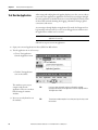
The table provides a comparison of function keys between the PanelView
Standard and PanelView Plus terminals.
Table 14 - Function Key Comparisons Between Terminal Platforms
PanelView Standard
Keypad or Keypad/Touch
PanelView Standard
Function Keys
300M keypad
F1…F4
300 keypad
F1…F8
F1…F8
400 keypad or keypad/touch
550 keypad or keypad/touch
F1…F10
F1…F10
600 keypad or keypad/touch
600 keypad or keypad/touch
F1…F10
F1…F10, K1…K12
700 keypad or keypad/touch
900 keypad
F1…F16
F1…F16, K1…K16
1000 keypad or keypad/touch
1000 keypad
F1…F16
F1…F20, K1…K20
1250 keypad or keypad/touch
1400 keypad
F1…F16, F17…F21
F1…F20, K1…K20
1500 keypad
Installing a PanelView Plus
Terminal
PanelView Plus
Function Keys
PanelView Plus Terminal
Keypad or Keypad/Touch
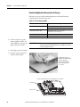
Optionally install the selected PanelView Plus terminal into the existing
PanelView Standard panel cutout. You may need an adapter plate depending on
your terminal selection.
TIP
You can install the terminal after converting and testing your application.
Refer to Additional Resources on page 11 for a list of applicable documentation
for your terminal replacement and adapter plate, if required.
24
Rockwell Automation Publication 2711P-AP002A-EN-P - February 2011
Chapter
3
Import Your Application
Introduction
In this chapter, you will import your existing PanelBuilder32 application into
FactoryTalk View Machine Edition (ME) software.
Different software is used by the PanelView Standard and PanelView Plus
platforms to develop applications.
• PanelView Standard terminals run applications created with
PanelBuilder32 software.
• PanelView Plus terminals run applications created with
FactoryTalk View ME software.
Before You Begin
• Review the migration considerations (Chapter 1).
• Select a PanelView Plus terminal replacement and adapter plate, if required
(Chapter 2).
• Optionally install the PanelView Plus terminal replacement (Chapter 2).
You can install the terminal after migrating and testing your application.
What You Need
• FactoryTalk View Studio for Machine Edition software with correct
version for your PanelView Plus terminal. Refer to Required Software on
page 10 for details.
• PanelBuilder32 .pba application file.
The application file can reside on your local hard drive or external storage
media:
– Secure Digital (SD) card or USB flash drive for PanelView Plus 6
terminals
– USB flash drive for PanelView Plus 6 or PanelView Plus terminals
– CompactFlash cards for PanelView Plus 400, 600, 700 to 1500
terminals, running FactoryTalk View ME software version 5.1 or earlier
Rockwell Automation Publication 2711P-AP002A-EN-P - February 2011
25
Chapter 3
Import Your Application
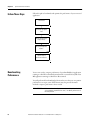
Follow These Steps
Follow these steps to import your PanelBuilder32 application into FactoryTalk
View Machine Edition software.
Import Application
page 27
Post Conversion Tips
page 30
26
Rockwell Automation Publication 2711P-AP002A-EN-P - February 2011
Import Your Application
Import Application
Chapter 3
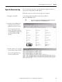
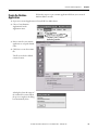
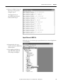
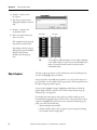
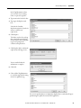
Follow these to import a PanelBuilder32 application into FactoryTalk View
Machine Edition software.
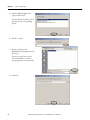
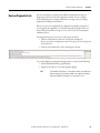
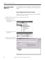
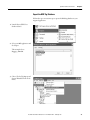
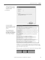
1. Launch the FactoryTalk View
Studio software.
2. Click the New tab.
3. Enter an Application name and
click Import.
4. Read the FactoryTalk View
dialog box and click OK.
RSLinx Enterprise software for
FactoryTalk View doesn’t need
to be installed before you import
your PanelBuilder32
application.
Rockwell Automation Publication 2711P-AP002A-EN-P - February 2011
27
Chapter 3
Import Your Application
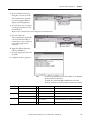
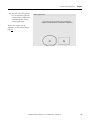
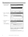
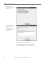
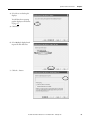
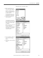
5. Select PanelBuilder Application
(*.pba) and click Next.
Select PanelView Terminal (*.pva) if
you don’t have the corresponding
.pba file.
6. Click the ... button.
7. Browse to and select your
PanelBuilder32 .pba application and
click Open.
The .pba or .pva file can reside on
your local hard drive or external
storage appropriate to your terminal.
8. Click Next.
28
Rockwell Automation Publication 2711P-AP002A-EN-P - February 2011
Import Your Application
Chapter 3
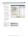
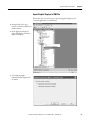
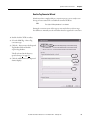
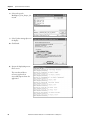
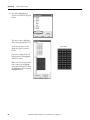
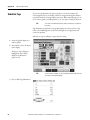
9. Configure the import options
based on your replacement
terminal.
Click Help at any time for
clarification of each option.
a. Check the Convert to new
window size checkbox.
b. Select the size (in pixels) of
your PanelView Plus
terminal display as shown in
chart.
c. Check Scale graphic displays.
When checked, this setting
rescales all displays.
d. If your original PanelView
Standard terminal had a
touch screen, or a both a
touch screen and keypad,
check the box under Touch
property conversion.
e. Click the Help button to
read the differences between
the caption alignment
options, then select an
option for your new
application.
f. Click Finish.
The Importing Project dialog
box shows the conversion status.
This process may take a while,
depending on the size of your
application. When done, you
will see the Project Status dialog
box in the next step.
Rockwell Automation Publication 2711P-AP002A-EN-P - February 2011
29
Chapter 3
Import Your Application
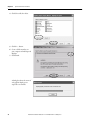
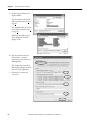
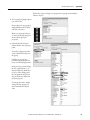
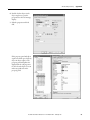
10. Review the Project Status dialog box and click OK.
11. Repeat steps 1…10 for each PanelBuilder32 application you want to import into FactoryTalk View ME software.
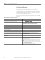
Post Conversion Tips
This table lists topics to consider after importing an application.
Table 15 - Post Conversion Tips
30
Software Feature
Description
What You Need To Do
Logout button
A Logout button assigned to a function
key in a PanelBuilder32 project will not
convert properly in the Machine
Edition application.
Reassign the function key manually.
Device shortcuts
After importing a PanelBuilder32 .pba
project, you may not see the newly
created device shortcuts in the Tag
Browser.
Restart FactoryTalk View Studio
software.
When you re-open the imported
application, the shortcuts will
display correctly.
Screens
When you import PanelBuilder32
Nothing
projects, all screens will be minimized.
Multistate objects
The first state value of PanelBuilder32
multistate objects is 1.
In Machine Edition software, the first
state value of multistate objects is 0.
Rockwell Automation Publication 2711P-AP002A-EN-P - February 2011
If the imported application contains
any of these multistate objects,
verify the state values:
• Control list selector
• List indicator
• Multistate indicator
• Latched push button
• Maintained push button
• Momentary push button
• Multistate push button
• Symbol indicator
Chapter
4
Review the Application Conversion Log
Introduction
In this chapter, you will review the conversion log generated by FactoryTalk View
Machine Edition (ME) software for your imported application. The results of
this log will help you to determine what updates are required in your converted
application.
Before You Begin
• Review migration considerations (Chapter 1).
• Select a PanelView Plus terminal replacement and adapter plate, if required
(Chapter 2).
• Install the PanelView Plus terminal in the existing PanelView Standard
panel cutout (Chapter 2).
• Import your PanelBuilder32 .pba application into FactoryTalk View ME
software (Chapter 3).
What You Need
• The new name of the application that was imported into FactoryTalk View
ME software. This was done in Chapter 3.
• Conversion log, convert.log, generated by the FactoryTalk View ME
import wizard.
Rockwell Automation Publication 2711P-AP002A-EN-P - February 2011
31
Chapter 4
Review the Application Conversion Log
Follow These Steps
Follow this path to review changes that are required to your FactoryTalk View
ME application.
About the Conversion
Log
page 32
Open the Conversion
Log
page 33
Review the Conversion
Log
page 34
About the Conversion Log
The application conversion log, convert.log, is generated by the import wizard
when you import your PanelBuilder32 application into FactoryTalk View ME
software. This log provides detailed information about objects or features that
did not convert directly from your PanelBuilder32 application. Use this log as a
guide to update your application accordingly. Modifications to the application
are required to verify that the application will operate correctly in FactoryTalk
View ME software.
IMPORTANT
32
It is important that you review each object and feature in the
converted application to verify that each will function as expected.
Because PanelBuilder32 objects or features may not map directly into
FactoryTalk View ME software, you may need to update your ladder
logic to achieve the same operational results.
Rockwell Automation Publication 2711P-AP002A-EN-P - February 2011
Review the Application Conversion Log
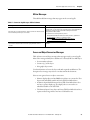
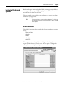
Open the Conversion Log
Chapter 4
The conversion log, convert.log, is stored with the new application that was
imported into FactoryTalk View ME software.
Follow these steps to locate the conversion log on your computer.
1. Navigate to this folder.
C:\Documents and Settings\All Users\Documents\RSView
Enterprise\ME\HMI projects\
TIP
All of your FactoryTalk View ME applications will be located in this
folder. This includes new or imported applications.
2. Double-click the HMI project
folder that contains the new
application name you created.
You entered this name in the
import wizard when importing
your PanelBuilder32 application
into FactoryTalk View ME
software.
3. Double-click the convert.log file
generated by the import wizard.
Your convert.log file will vary
from the example shown.
Rockwell Automation Publication 2711P-AP002A-EN-P - February 2011
33
Chapter 4
Review the Application Conversion Log
Review the Conversion Log
The conversion log file, convert.log, contains a list of messages including
warnings, errors, and unsupported features or objects in the converted
application. You can compare these messages to those in the tables for
information on why the message was logged. For your convenience, the message
tables are categorized into these groups:
• RSLinx software
• Tags
• Objects and screens
• Alarms
When resolving conversion log messages, refer to your original PanelBuilder32
application to review how the objects and tags were used.
During conversion, all PanelBuilder32 tag names and addresses are converted to
HMI tags in the FactoryTalk View ME tag database.
IMPORTANT
Some features or objects are no longer supported in FactoryTalk View
ME software. However, new features or objects are available
providing the same or enhanced functionality.
Conversion Messages You Can Ignore
Some error messages appear consistently when importing PanelBuilder32
projects and can be ignored.
Table 16 - Conversion Messages: To Be Ignored
34
Error Type
Ignore this Error
Startup editor
The initial screen does not exist in the graphics list.
Startup editor
Failed to get startup information.
Format error
File c:\documents and settings\all users\documents\rsview enterprise\me\hmi
project\app1\import text files\almsg.txt, section/key ’main’
Tags
Tags with a bit data type and a scale value of 0 are incorrectly logged during
the import.
Scale errors
Tag scale errors are logged only for analog tags.
Rockwell Automation Publication 2711P-AP002A-EN-P - February 2011
Review the Application Conversion Log
Chapter 4
RSLinx Messages
This table lists RSLinx messages that may appear in the convert.log file.
Table 17 - Conversion Log Messages: RSLinx Software
Message
Description
RSLinx Topic Converter log file created on <date> at <time>.
Review the HMI tags in FactoryTalk View ME software and note the
shortcut name. It is the same as the controller name in the PanelBuilder32
application. You must use this name when creating the shortcut in
FactoryTalk View ME software.
For information on creating shortcuts, refer to:
RSLinx2X topics to RSLinx Enterprise shortcuts conversion failed. User will
have to manually convert topics to shortcuts.
• FactoryTalk View Machine Edition User Guide, Volume 1, publication
ViewME-UM004, for details on creating shortcuts.
• Videos at http://www.rockwellautomation.com/solutions/
integratedarchitecture/resources4.html
RSLinx is not installed. Please install the latest RSLinx software for proper
import. Cannot create instance of RSLinx. Topic generation will not
succeed.
In FactoryTalk View ME software, set up communication and create a
shortcut.
Screen and Object Conversion Messages
Table 19 lists screen and object messages that may appear in the convert.log file.
Most of the messages identify these attributes for a FactoryTalk View ME object:
• Screen number and name
• Location (x,y) of the object
• New graphic object name
Use this information to locate the object and make required modifications. The
description for a message may reference a workaround in this document.
Here are some general notes on object conversions:
• Numeric display objects in PanelBuilder32 software are converted to Text
objects with embedded variables in FactoryTalk View ME software.
• A Numeric Input Enable button in FactoryTalk View ME software does
not have a separate display tag. The display value is converted to an
embedded variable on the Label Tab.
• The Numeric Input Cursor object in FactoryTalk View ME software has a
separate indicator tag and does not have a Label tab for text.
Rockwell Automation Publication 2711P-AP002A-EN-P - February 2011
35
Chapter 4
Review the Application Conversion Log
Table 18 - Conversion Log Messages: Screens and Objects
Message
Description
Message display object will be converted to Multistate Indicator object at
<location>.
A message display in PanelBuilder32 software is the same as a multistate
indicator in FactoryTalk View ME software.
Verify password button at <location> not supported.
The Verify Password button is not supported in FactoryTalk View ME
software.
Select Operator button at <location> not supported.
The Select Operator button is not supported in FactoryTalk View ME
software.
Screen security settings not converted.
Security settings are not converted in FactoryTalk View ME software. You
must reconfigure all security settings.
String pop up will be invoked with blank scratchpad on <location>.
Verify operation in FactoryTalk View ME software.
Cannot find block write start tag for pilot list selector at <location>. The
visible state connection will be unassigned.
The Piloted Control List Selector in PanelBuilder32 software does not have
a block write tag assigned.
Assign a block write tag in FactoryTalk View ME software if you want a
visible state connection.
For LSB support, refer to online help for correct syntax of Multistate
Indicator’s Value control at <location>.
FactoryTalk View ME software does support Least Significant Bit (LSB) on
multistate and list indicators. Check the object and make sure the syntax is
correct for the value.
The L parameter is used only for message addresses that are more than one
word in length. Refer to the FactoryTalk View online help for information on
the L parameter.
Blinking color images are not supported.
FactoryTalk View ME software does not support blinking color images.
Print Only objects not supported.
FactoryTalk View ME software does not support Print Only objects.
Line at <location> could not have property set: Width.
In FactoryTalk View ME software, lines have a line width that is separate
from the object location.
Line at <location> could not have property set: Height.
In FactoryTalk View ME software, lines have a line height that is separate
from the object location.
Numeric entry enable button at <location> could not have property set:
Minimum Value.
The Numeric Entry Enable button is converted to a Numeric Input Enable
button in FactoryTalk View ME software.
• In PanelBuilder32 software, the input and display floating point tags
shared the same name and address. The min/max values were out of
range and could not be set in the FactoryTalk View ME object.
• In FactoryTalk View ME software, set the default min and max for
floating point. The display value is an embedded variable on the
Label tab.
Numeric entry enable button at <location> could not have property set:
Maximum Value.
36
Rockwell Automation Publication 2711P-AP002A-EN-P - February 2011
Review the Application Conversion Log
Chapter 4
Tag Conversion Messages
This table lists tag messages that may appear in the convert.log file.
Table 19 - Conversion Log Messages: Tags
Message
Description
Invalid characters not supported. Tag has been converted to <name>.
FactoryTalk View ME software does not support periods in tag names. The
periods are converted to underscores.
Already exists in the tag database.
The converted tag already exists in the FactoryTalk View ME HMI tag
database or the conversion created it.
Could not be added to the tag database.
Verify that all the tag names exist in the FactoryTalk View HMI tag
database after the conversion.
The minimum value for this tag was invalid and has been set to the
minimum value based on the tag’s data type.
The minimum value for the tag in the PanelBuilder32 application is not valid
in the FactoryTalk View ME application. This discrepancy was corrected.
The minimum value for the tag was set according to the tag’s data type.
Verify that the tag data type and minimum value are correct.
The maximum value for this tag was invalid and has been set to the
minimum valid value based on the tag’s data type.
The maximum value for the tag in the PanelBuilder32 application is not
valid in the FactoryTalk View ME application. This discrepancy was
corrected. The maximum value for the tag was set according to the tag’s
data type. Verify that the tag data type and maximum value are correct.
The scale for this tag was invalid and has been set to its default value.
Verify that the scale for the tag data type is correct.
Tag converted to memory tag, as its addressing syntax is not supported.
For this specific instance, an RIO bit array data type with a length of 2 is
using output O:xxx address.
In the converted application. FactoryTalk View ME software does not
support bit arrays. Bit arrays are converted to memory tags.
Tag converted to memory tag, as its address is blank.
The tag was converted to a memory tag because the tag address was blank
in the PanelBuilder32 software.
The array size for this tag was invalid and has been set to the maximum
supported size.
The character array size was converted to the maximum string length of 82
in the FactoryTalk View ME application.
Bit array tags are not supported. Tag will be converted as a memory tag.
FactoryTalk View ME software does not support the bit array data type.
Typically, bit arrays were used in PanelBuilder32 software for addresses
less than one word in length.
In FactoryTalk View ME software, change the tag address to a full word
address. When using non-Remote I/O addresses these conversions take
place:
• Bit array is converted to an analog, default type Device tag with a word
length as opposed to a memory tag.
• BOOL is converted to a bit tag.
• DINT is converted to an analog, long integer tag.
Rockwell Automation Publication 2711P-AP002A-EN-P - February 2011
37
Chapter 4
Review the Application Conversion Log
Alarm Conversion Messages
This table lists alarm messages that may appear in the convert.log file.
For optimal performance, convert PanelBuilder32 alarm tags to direct reference
tags in FactoryTalk View ME software. Use the L parameter for the length in
16 bit words. The alarm trigger type can be bit.
Refer to the FactoryTalk View online help for information on the word length
L parameter.
Table 20 - Conversion Log Messages: Alarms
Message
Description
Bit and LSBit triggered alarms that used a trigger tag with a bit data type
will only be able to trigger a single alarm after import.
Refer to Alarm Trigger Tags on page 15 for details on alarm tag data types.
Alarm message Ack option not supported.
In PanelBuilder32 software, the alarm ACK is on an individual message.
FactoryTalk View ME software does not support individual
acknowledgement of alarms. The alarm Ack is on the triggers.
Alarm List at <location> will display all alarms.
This message describes the type of alarm list.
Alarm List at <location> will display all active alarms.
This message describes the type of alarm list.
Alarm List at <location> will display all alarms that have come out of alarm. This message describes the type of alarm list.
Alarm List at <location> does not support displaying alarms that do not
require acknowledgement.
This message describes the type of alarm list.
“Remote Clear All Alarm Tag” alarm control not supported.
FactoryTalk View ME software does not support this alarm tag.
“Remote Clear All Alarm Handshake Tag” alarm control not supported.
FactoryTalk View ME software does not support this alarm tag.
Tag converted to memory tag, as its address is blank.
The tag was converted to a memory tag because the tag address was blank
in PanelBuilder32 software.
The array size for this tag was invalid and has been set to the maximum
supported size.
The character array size was converted to the maximum string length of 82.
Bit array tags are not supported. Tag will be converted as a memory tag.
FactoryTalk View ME software does not support the bit array data type.
Typically, bit arrays were used in PanelBuilder32 software for addresses
less than one word in length.
In FactoryTalk View ME software, change the tag address to a full word
address. When using non-Remote I/O addresses, these conversions take
place:
• Bit array is converted to an analog, default type device tag with a word
length as opposed to a memory tag.
• BOOL is converted to a bit tag.
• DINT is converted to an analog, long integer tag.
38
Rockwell Automation Publication 2711P-AP002A-EN-P - February 2011
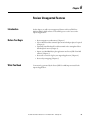
Chapter
5
Review Object Mapping
Introduction
Before You Begin
What You Need
In this chapter, you will review how objects and alarms from PanelBuilder32
software map to FactoryTalk View Machine Edition (ME) software.
• Review migration considerations (Chapter 1).
• Select a PanelView Plus terminal replacement and adapter plate, if required
(Chapter 2).
• Optionally install the PanelView Plus terminal in the existing PanelView
Standard panel cutout (Chapter 2).
• Import your PanelBuilder32 .pba application into FactoryTalk View ME
software (Chapter 3).
• Review the conversion log for your imported application (Chapter 4).
Conversion log generated by the FactoryTalk View ME Import Wizard for the
imported application.
Rockwell Automation Publication 2711P-AP002A-EN-P - February 2011
39
Chapter 5
Review Object Mapping
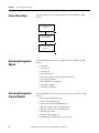
Follow These Steps
Follow these steps to review how PanelBuilder32 objects and alarms map to
FactoryTalk View ME software. This information will help you correct
application errors listed in the conversion log.
Reviewing Object
Mapping
page 40
Reviewing Data Type
Mapping
page 41
Reviewing Mapping of
Communication Networks
page 41
Reviewing Object Mapping
This table identifies how some PanelBuilder32 graphic objects migrate into a
FactoryTalk View ME application.
IMPORTANT
It is important that you verify the function of all objects after
importing your application to FactoryTalk View ME software. New
objects may not function as expected.
Table 21 - Object Mapping
This PanelBuilder32 object
Maps to this FactoryTalk View ME object
Message Display
Multistate Indicator
Numeric Entry Cursor Point
Numeric Input Enable
Increment/Decrement Entry
Numeric Input Enable
ASCII Entry Cursor Point
String Input Enable
Numeric Display
Text object with numeric embedded variable
Connected Line
Polyline
Circle
Ellipse
Freeform
Freehand
Bar Graph and Gauge Inner Text
Bar Graph with separate Text object
Bar Graph and Gauge Inner Graphic
Bar Graph with separate Image object
Gauge Needle
Separate Gauge object.
For example, in PanelBuilder32 software, a Gauge object is
configured with two needles. This object is converted to two
separate Gauge objects in Machine Edition software.
40
Rockwell Automation Publication 2711P-AP002A-EN-P - February 2011
Review Object Mapping
Reviewing Data Type
Mapping
Chapter 5
This table shows how data types map between PanelBuilder32 and Machine
Edition software.
Table 22 - Data Type Mapping
Reviewing Mapping of
Communication Networks
PanelBuilder32 Data Types
Machine Edition Data Types
Bit
Digital
Bool
Digital
Char array
String (82 character max)
Unsigned integer
Unsigned
Signed integer
Int
IEEE
Floating Point (FP)
4BCD
4BCD
none
3BCD
none
Byte (unsigned 0…255)
Bit array
None
DINT
Long Int (signed 32 bit)
SINT (8 bit signed)
None
This table shows communication protocols supported by PanelBuilder32 and
FactoryTalk View ME applications.
Table 23 - Mapping of Communication Networks
PanelBuilder32
Communication Protocols
FactoryTalk View ME
Communication Protocols
RS-232 (DF1)
RS-232 (DF1)
RS-232 (DH-485)
RS-232 (DH-485)
DH-485
DH-485
DH+
DH+
Does not support nodes that use the
AutoMax node type
EtherNet/IP
– EtherNet/IP controller address
– EtherNet/IP CIP
– Assembly object
EtherNet/IP
– Supported
– Not supported
– Not supported
RIO
RIO (1)
DeviceNet
Not supported (1)
ControlNet
ControlNet
KEPWare communication drivers for
third-party controllers
(1) Remote I/O and DeviceNet communication modules are not available for
PanelView Plus 6 terminals.
Rockwell Automation Publication 2711P-AP002A-EN-P - February 2011
41
Chapter 5
Review Object Mapping
Notes:
42
Rockwell Automation Publication 2711P-AP002A-EN-P - February 2011
Chapter
6
Review Unsupported Features
Introduction
Before You Begin
What You Need
In this chapter, you will review unsupported features in FactoryTalk View
Machine Edition (ME) software. This will help you to resolve errors in the
imported application.
• Review migration considerations (Chapter 1).
• Select a PanelView Plus terminal replacement and adapter plate, if required
(Chapter 2).
• Optionally install the PanelView Plus terminal in the existing PanelView
Standard panel cutout (Chapter 2).
• Import your PanelBuilder32 .pba application into FactoryTalk View ME
software (Chapter 3).
• Review the conversion log for your migrated application (Chapter 4).
• Review object mapping (Chapter 5).
Conversion log generated by the FactoryTalk View ME import wizard for the
imported application.
Rockwell Automation Publication 2711P-AP001A-EN-P - February 2011
43
Chapter 6
Review Unsupported Features
Follow These Steps
Follow this path to review unsupported features in FactoryTalk View ME
software.
Reviewing Unsupported
Objects
page 45
Reviewing Unsupported
Tags and Controls
page 44
Reviewing Unsupported
Features
page 45
Reviewing Unsupported
Objects
These PanelBuilder32 objects are not supported in FactoryTalk View ME
software:
• Print Only
• Circular Scale
• Scrolling Text
• Print Alarm Button
• Horn Silence Button and Lamp/Horn Test Button
• Select Operator Button
• Enable/Disable Security Button
• New Password Button
• Verify Password Button
Reviewing Unsupported
Tags and Controls
These PanelBuilder32 controls are not supported in Factory Talk View ME
software:
• Remote Ack All Handshake tag
• Remote Clear All Alarm tag
• Remote Clear All Alarm Handshake tag
• Message to Remote Device Notification tag
• Message to Remote Device Handshake tag
• Ack setting for alarms
• Bit alarm acknowledgement
• Handshaking for alarms sent to a remote device
44
Rockwell Automation Publication 2711P-AP001A-EN-P - February 2011
Review Unsupported Features
Reviewing Unsupported
Features
Chapter 6
Some PanelBuilder32 features are not supported in FactoryTalk View Machine
Edition software. Compare the conversion log with the information on
unsupported features to assist with updates to your imported application.
Additional information is provided where possible to achieve the same
functionality using another option or workaround in your imported application.
Table 24 - Unsupported Features in FactoryTalk View Machine Edition
Unsupported Feature
Object
Additional Information
Blink
Text
Arc Ellipse
Line
Panel
Rectangle
Wedge
In FactoryTalk View ME software, all of the list objects use
color animation to blink.
Image
Color images do not blink.
Monochrome images use the Blink property to enable
blinking.
Allow Home/End
Allow Wrap
Ramping by Coarse Steps
Increment/Decrement Entry Button
(Converted to Numeric Input Enable
Button)
The Increment/Decrement Entry button is converted to a
Numeric Input Enable button in FactoryTalk View ME
software.
Print Setting
Multistate Indicator
Message Display
Printing
Print Only Object
This object is not supported in FactoryTalk View ME
software.
Initial State Values
Maintained Push button
Multistate Push button
Standard Control List Selector
To set the states of these objects on application startup,
create a macro to set the appropriate tag values for the
object’s controls. Assign the Macro in the Startup editor of
FactoryTalk View ME software.
Least Significant Bit data format
Multistate Indicator
Message Display
List Indicator
Standard Control List Selector
Bit triggered states are not supported in FactoryTalk View
ME software. Modify the state values and the read tag, or
assign an expression to return the value of the Least
Significant Bit.
Inner Text and Inner Graphic
Bar Graph
Gauge
In FactoryTalk View ME software, the Inner Text is
converted to a separate Text object. The Inner Graphic is
converted to a separate Image object.
Scale Clipping
Gauge
If the scale doesn’t fit within the height or width of the
gauge, it is not clipped. Check the position of the scale to
make sure it doesn’t overlap other objects.
Needle
Gauge
In FactoryTalk View ME software, each needle is converted
to a separate Gauge object.
No Acknowledgement
Alarm List
In FactoryTalk View ME software, all alarms can be
acknowledged.
Ack Setting
Alarm messages
In FactoryTalk View ME software, all alarms can be
acknowledged.
Turn Object View On property
All objects
If this property is set to False, the converted object does
not appear.
Embedded Variable
Numeric Display
Numeric Display objects are converted to Text objects with
embedded variables.
Rockwell Automation Publication 2711P-AP001A-EN-P - February 2011
45
Chapter 6
Review Unsupported Features
Table 24 - Unsupported Features in FactoryTalk View Machine Edition
Unsupported Feature
Object
Additional Information
Foreground and background colors
All objects
The foreground and background colors of PanelBuilder32
objects are used to set the Selection Fore and Selection
Back color for FactoryTalk View ME objects.
If the foreground and background colors are the same, the
Selection Fore and Back colors are also the same. This
means the selected state will be invisible, because the
foreground color (text) and the background color are the
same.
To make the selected state visible, edit the object to
change either the Selection Fore or Selection Back color.
Selected state visibility during design time and
runtime
List Indicator
Display List Selector
Control List Selector
Piloted Control List Selector
Alarm List Selector
If the original Foreground Color (text) and Background
Color of the object are the same, the selected state will be
invisible. To make the selected state visible, edit the
object to change either the Selection Fore or Selection
Back color.
Caption and image placement
All objects
FactoryTalk View ME software supports one, three, or nine
positions for captions and images, depending on the type
of object. On conversion, captions and images are
positioned using the closest match. Some captions might
do the following:
• Overlap images
• Get truncated
• Get clipped to fit the object
Realign or resize objects for best fit.
Goto Configure Mode Button
Object not converted
Security
Enable/Disable Security Button
New Password Button
Verify Password Button
In the PanelBuilder32 software, user passwords are set up
in the Configuration mode screens. FactoryTalk View ME
software requires the Change Password button on a
display.
Security Settings
FactoryTalk View ME software uses a different method to
assign security to graphic displays.
You must reconfigure security. Once logged on, the
operator does not need to re-enter the password until
manually logged off, or optionally after an idle time.
46
Rockwell Automation Publication 2711P-AP001A-EN-P - February 2011
Chapter
7
Qualify the Runtime Application
Introduction
Before You Begin
What You Need
In this chapter, you will qualify the integrity of your converted application before
downloading and running it in your production environment. Because you are
using different software with new features and functionality, it is important to
validate the application for proper operation.
• Review migration considerations (Chapter 1).
• Select a PanelView Plus terminal replacement and adapter plate, if required
(Chapter 2).
• Optionally install the PanelView Plus terminal in the existing PanelView
Standard panel cutout (Chapter 2).
• Import your PanelBuilder32 .pba application into FactoryTalk View ME
software (Chapter 3).
• Review the conversion log for your migrated application (Chapter 4).
• Review object mapping (Chapter 5).
• Review unsupported features (Chapter 6).
Converted FactoryTalk ME application.
Rockwell Automation Publication 2711P-AP001A-EN-P - February 2011
47
Chapter 7
Qualify the Runtime Application
Follow These Steps
Follow these steps to configure diagnostics, validate, test run, configure global
memory connections, download, and run your converted application on a
PanelView Plus terminal.
Review Diagnostic Lists
page 49
Configure the Runtime
Diagnostic Display
page 50
Review Error States for
Graphic Objects
page 51
Configure
Communication
page 52
Test Run Graphic Displays
page 54
Test Run the Application
page 56
48
Rockwell Automation Publication 2711P-AP001A-EN-P - February 2011
Qualify the Runtime Application
Review Diagnostic Lists
Chapter 7
On your development computer, FactoryTalk View ME software features a
diagnostic list at the bottom of the application window. You can configure
FactoryTalk diagnostics to display information, warnings, and errors during
application development and runtime.
When you test run your application, the diagnostic list displays messages and
errors logged by the application. Use this list to identify the graphic objects or
features that generated the messages or errors. Correct these errors during the
validation process.
The diagnostic lists lets you clear one or all messages in the list:
• Click the Clear button to delete the message that is displayed.
If you resize the list to display more than one message, select a message and
then click Clear.
• Click the Clear All button to delete all messages in the list.
To view this diagnostic information during runtime, use either of the following:
• Default [DIAGNOSTICS] graphic display
• Diagnostic list object in a customized graphic display
TIP
The [DIAGNOSTICS] display is in the Libraries editor of the application
Explorer window if not already included in your application displays.
Import the [DIAGNOSTIC] display if you are going to use it.
Rockwell Automation Publication 2711P-AP001A-EN-P - February 2011
49
Chapter 7
Qualify the Runtime Application
Configure the Runtime
Diagnostic Display
Follows these steps to configure the default [DIAGNOSTICS] display to log
errors or warnings generated during runtime operation.
1. Launch FactoryTalk View ME software if not open.
2. Open your converted application.
3. Expand the System folder in
your application Explorer
window.
4. Double-click Diagnostic List
Setup.
5. Under Runtime display, verify
that [DIAGNOSITICS] is the
Display name.
This is the default diagnostic
display that pops up during
runtime when configured events
occur.
6. Check the boxes next to the
messages that you want to
appear in the display when
events occur during runtime.
It is recommended that you
always log errors and warnings
during runtime.
For information on how each
dialog option is designed to
function during runtime, click
Help.
7. Click OK.
50
Rockwell Automation Publication 2711P-AP001A-EN-P - February 2011
Qualify the Runtime Application
Review Error States for
Graphic Objects
Chapter 7
In FactoryTalk View ME software, error conditions for visible objects may be
different than those in PanelBuilder32 software. The table clarifies what happens
when errors occur for objects when tags are unavailable or communication is lost.
For additional information on objects, refer to the FactoryTalk View Machine
Edition online help.
Table 25 - Error Modes for Objects
Graphic Object
Visible Error Mode
•
•
•
•
The caption displays ‘default error message’ for
the error state.
Momentary Push Button
Maintained Push Button
Latched Push Button
Multistate Push Button
• Interlock Push Button
• Ramp Push Button
No visible error message or error condition is
displayed.
When you click on these objects, an error
message is generated and logged to the
diagnostic list object.
• Numeric Display
• Numeric Input Cursor
These objects display asterisks, ******.
• Numeric Input Enable
• String Input Enable
• String Display
No visible error message or error condition is
displayed.
When you click on these objects, an error
message is generated and logged to the
diagnostic list object.
•
•
•
•
No visible error message or error condition is
displayed.
If communication to the PLC controller is lost,
these buttons still let you navigate through your
application.
Goto Display Button
Return To Display Button
Display List Selector
Close Display Button
Multistate Indicator
The caption displays Error for the error state.
Symbol Properties
The object shows the image color defined in the
error state.
List Indicator
No visible error message or error condition is
displayed.
Bar Graph Gauge
This object shows a transparent wireframe box.
Scale
No visible error message or error condition is
displayed.
Local Message Display
This object displays question marks, ???????, in
the error state.
•
•
•
•
•
•
•
•
•
Backspace
End
Enter
Home
Move Left
Move Right
Move Down
Page Up
Page Down
No visible error message or error condition is
displayed.
•
•
•
•
Sort Alarm
Reset Alarm
Alarm Banner
Alarm Status List
No visible error message or error condition is
displayed.
Rockwell Automation Publication 2711P-AP001A-EN-P - February 2011
51
Chapter 7
Qualify the Runtime Application
Table 25 - Error Modes for Objects
Configure Communication
Graphic Object
Visible Error Mode
Display Print
No visible error message or error condition is
displayed.
Trend
This object appears not to have any pens and
does not perform real-time trending.
Time and Date
No visible error message or error condition is
displayed.
You are now ready to configure communication for your imported application.
Because this is a new application, a communication configuration does not exist.
The configuration will vary depending on the communication protocol you use.
Follow these steps to configure communication for your application.
1. In the Explorer window, expand
RSLinx Enterprise and doubleclick Communication Setup.
2. Select Create a New
Configuration and click Finish.
52
Rockwell Automation Publication 2711P-AP001A-EN-P - February 2011
Qualify the Runtime Application
Chapter 7
3. In the Communication Setup
dialog box, select the Local tab.
This communication path will
be used for testing individual
displays and Test Application.
4. Select the driver you are using in
your design environment to test
communication.
Browse to the controller device and configure local communication.
5. Select the Target tab.
This communication path will be
used on the PanelView Plus to
communicate to the controller in
your runtime application in
Chapter 8.
6. Right-click RSLinx Enterprise
and select Add Driver.
7. Select the appropriate driver and
click OK.
8. Configure the driver properties.
Remote I/O and DeviceNet communication modules are not supported
by the PanelView Plus 6 terminals.
TIP
PanelView Plus Compact 400, 600, and 1000 terminals are fixed
hardware configurations that do not support communication modules.
For
On This Terminal
+
Communication Module
Select
DH+
PanelView Plus 6 (700 to 1500)(1)
+
2711P-RN6 or 2711P-RN6K
DH+ (1784-PKTX, 2711P-RN6, 2711P-RN8)
PanelView Plus 400 or 600
+
2711P-RN8
DH+ (1784-PKTX, 2711P-RN6, 2711P-RN8)
PanelView Plus 6 (700 to 1500)(1)
+
2711P-RN6 or 2711P-RN6K
DH485 (1784-PKTX, 2711P-RN6)
PanelView Plus 400 or 600
+
2711P-RN3
Serial DH485 (including 2711P-RN3, 2711P-RN22C)
PanelView Plus 6 (700 to 1500)(1)
+
2711P-RN15S or
2711P-RN15SK
ControlNet (1784-PCIC, 1784-PCICS, 2711P-RN15S) or
ControlNet (1784-PKTCS, 2711P-RN15S, 2711P-RN15C)
PanelView Plus 400 or 600
+
2711P-RN15C
ControlNet (1784-PKTCS, 2711P-RN15S, 2711P-RN15C)
DH-485
ControlNet
(1) Also applies to PanelView Plus 700 to 1500 terminals running FactoryTalk View Machine Edition Firmware Revision 5.1 or earlier.
Rockwell Automation Publication 2711P-AP001A-EN-P - February 2011
53
Chapter 7
Qualify the Runtime Application
ControlNet Communication
Refer to ControlNet Communication for PanelView Plus Terminals user manual,
publication, 2711P-UM003, for step-by-step details on how to configure
ControlNet Scheduled and Unscheduled communication with FactoryTalk View
ME software.
Test Run Graphic Displays
FactoryTalk View ME software provides a Test Display mode to test the
animation and assigned tags connected to objects in a graphic display. Any
information, warning, or errors are logged to the diagnostic list for your review.
Test Display mode tests all objects in a display:
• Button objects
• Numeric and string objects to verify that correct values are displayed
• Objects that require user input
• Objects that use animation
IMPORTANT
You must be connected to the controller and online before test running
the display or all objects will show their error states.
For each object tested, review and correct any errors and warnings logged to the
diagnostic list. Retest the display object before proceeding to the next object.
IMPORTANT
54
In Test Display mode, objects in the display are activated and
connected to assigned tags. Only tags connected to objects in the
display will work. Links to other displays or alarms, including data
logging, macros, global connections, and information messages will
not work.
Rockwell Automation Publication 2711P-AP001A-EN-P - February 2011
Qualify the Runtime Application
Chapter 7
Follow these steps to activate Test Display mode for a display and then return to
Edit mode. Running Test Display mode and correcting logged errors in Edit
mode is an iterative process.
1. Open the display you want to test.
2. Access Test Display mode in one of two ways.
• Choose Test Display from the
View menu.
• Click the Test Display button
on the toolbar.
3. Return to Edit mode in one of two ways.
• Choose Edit Display from
the View menu.
• Click the Edit Display button
on the toolbar.
Rockwell Automation Publication 2711P-AP001A-EN-P - February 2011
55
Chapter 7
Qualify the Runtime Application
Test Run the Application
After testing and verifying that each graphic display is error free, you are ready to
test run the entire application. Application Test mode lets you navigate through
the entire application to validate functions not tested in Display Test mode. Some
of these features include alarming, data logging, information messages, global
connections, and macros.
As you navigate through displays in Application Test mode, the Diagnostic List
logs warnings and errors as they occur. Correct all logged errors and then retest
the application to validate error correction.
IMPORTANT
You must be connected to the controller and online before testing the
application for accuracy.
Follow these steps to test run an application.
1. Open your converted application in FactoryTalk View ME software.
2. Test the application in one of two ways.
• Choose Test Application
from the Application menu.
• Click the Test Application
icon on the toolbar.
The emulator opens on your
computer and runs the
application. There is a two hour
limit for using the runtime
emulator.
3. Press x on your keyboard to exit
the emulator.
56
TIP
Local messages and graphic objects configured for multiple
languages will display in the application’s current language while in
Test Application mode.
TIP
The emulator window requires focus when pressing the x key to exit
the emulator.
Rockwell Automation Publication 2711P-AP001A-EN-P - February 2011
Chapter
8
Create the Runtime Application
Introduction
In this chapter, you will create, download, and run the converted application with
all modifications on the PanelView Plus terminal.
Before You Begin
• Review migration considerations (Chapter 1).
• Select a PanelView Plus terminal replacement and adapter plate, if required
(Chapter 2).
• Optionally install the PanelView Plus terminal in the existing PanelView
Standard panel cutout (Chapter 2).
• Import your PanelBuilder32 .pba application into FactoryTalk View ME
software (Chapter 3).
• Review the conversion log for your migrated application (Chapter 4).
• Review object mapping (Chapter 5).
• Review unsupported features (Chapter 6).
• Qualify the runtime application (Chapter 7).
What You Need
• Converted FactoryTalk View ME application.
• Qualified runtime application.
Rockwell Automation Publication 2711P-AP001A-EN-P - February 2011
57
Chapter 8
Create the Runtime Application
Follow These Steps
Follow these steps to create a runtime application, download, and run the
application on the PanelView Plus terminal.
Create the Runtime
Application
page 59
Download the Runtime
Application
page 60
Run the Application
page 66
58
Rockwell Automation Publication 2711P-AP001A-EN-P - February 2011
Create the Runtime Application
Create the Runtime
Application
Chapter 8
Follow these steps to create a runtime application file from your converted
Machine Edition .mer file.
1. Open your converted application in FactoryTalk View ME software.
2. Choose Create Runtime
Application from the
Application menu.
3. Enter a name for your runtime
application or accept the default
name.
4. Click Save to create the runtime
file.
The file is saved to the default
runtime location.
A dialog box shows the status of
the runtime file creation. When
the process completes, the dialog
box automatically closes.
Rockwell Automation Publication 2711P-AP001A-EN-P - February 2011
59
Chapter 8
Create the Runtime Application
Download the Runtime
Application
You can download your runtime .mer application to a PanelView Plus terminal
using an Ethernet connection or external storage device that is supported by your
terminal.
Download Application Using Ethernet Connection
Follow these steps to download your runtime application to the PanelView Plus
terminal using an Ethernet connection.
1. Establish an Ethernet connection between your computer and the terminal.
2. Launch the transfer utility in
one of two ways.
a. Choose Transfer Utility from
the Tools menu.
b. Click the appropriate tool on
the toolbar.
3. Click the ... button to browse for
the runtime file you just created.
60
Rockwell Automation Publication 2711P-AP001A-EN-P - February 2011
Create the Runtime Application
Chapter 8
4. Select the runtime file you just
created and click Open.
5. Under Select destination
terminal, expand the Ethernet
driver.
6. Browse for and select your
PanelView Plus terminal.
7. Click Download to download
the runtime file to the
PanelView Plus terminal.
A progress bar shows the status
of the download.
s
Rockwell Automation Publication 2711P-AP001A-EN-P - February 2011
61
Chapter 8
Create the Runtime Application
8. Click OK when the download
has completed successfully.
9. On the PanelView Plus terminal,
load the application by pressing
the Load Application button or
pressing the [F1] function key.
10. Select your runtime application.
a. Press the up or down cursor
to select the application if
more than one exists.
b. Press the Load button or the
[F2] function key on
terminal.
PVs_App.mer
62
Rockwell Automation Publication 2711P-AP001A-EN-P - February 2011
Create the Runtime Application
Chapter 8
11. Press Yes or the [F7] function
key on terminal to replace the
communication settings in the
terminal with those in your
runtime application.
You are now ready to run the
application on the terminal. Skip to
page 66.
Rockwell Automation Publication 2711P-AP001A-EN-P - February 2011
63
Chapter 8
Create the Runtime Application
Download Application Using External Storage
Follow these steps to load the runtime application on the PanelView Plus
terminal using an external storage card.
Table 26 - External Storage Media
This Terminal Platform
Supports This External Storage
PanelView Plus 6 (700 to 1500)
Secure Digital (SD) card, cat. no. 1784-SDx
USB flash drive on USB host ports
1. On your computer, copy the
runtime application file to the
runtime folder on a storage card
supported by the terminal.
PanelView Plus 700 to 1500
CompactFlash cards, cat. no. 2711P-RCx
USB flash drive on USB host ports
PanelView Plus 400 and 600
CompactFlash cards, cat. no. 2711P-RCx
PanelView Plus Compact
CompactFlash cards, cat. no. 2711P-RCx
IMPORTANT
The root of the CompactFlash card must have the path
‘RockwellSoftware\RSViewME\Runtime’ or the application file will
not be recognized at runtime.
2. Turn off power to the terminal.
3. Load the storage card into the
card slot of the terminal.
CompactFlash card slot on
PanelView Plus 700 and 1500
terminals supporting
FactoryTalk View Machine
Edition software version
5.1 or earlier.
SD card slot and USB host port on PanelView Plus 6 terminals
SD Card Slot
USB Host Ports
64
Rockwell Automation Publication 2711P-AP001A-EN-P - February 2011
Create the Runtime Application
Chapter 8
4. Turn on power to the PanelView
Plus terminal.
5. On the configuration display,
press Load Application or the
[F1] function key on the
terminal.
6. Press the Source button or [F1]
on the terminal to select
External Storage 1 or 2.
7. Select your runtime application.
c. Press the up or down cursor
to select the application if
more than one exists.
d. Press the Load button or [F2]
function key on the terminal.
PVs_App.mer
Rockwell Automation Publication 2711P-AP001A-EN-P - February 2011
65
Chapter 8
Create the Runtime Application
8. Press Yes or the [F7] function
key on the terminal to replace
the communication settings in
the terminal with those in your
runtime application.
Run the Application
Follow these steps to run your application on a PanelView Plus terminal.
1. Press Run Application or the
[F2] function key on the
terminal to run the currently
loaded application.
PVs_App.mer
IMPORTANT
If your application is not communicating to the controller:
• Check all cable connections.
• Verify that the Target tab in the RSLinx Enterprise Communication
Setup is configured correctly.
2. Cycle through all the runtime displays continuously.
66
Rockwell Automation Publication 2711P-AP001A-EN-P - February 2011
Chapter
9
Optimize Runtime Performance
Introduction
In this chapter, you will learn how to benchmark performance of your runtime
application so that you can optimize as needed.
Before You Begin
• Review migration considerations (Chapter 1).
• Select a PanelView Plus terminal replacement and adapter plate, if required
(Chapter 2).
• Optionally install the PanelView Plus terminal in the existing PanelView
Standard panel cutout (Chapter 2).
• Import your PanelBuilder32 .pba application into FactoryTalk View ME
software (Chapter 3).
• Review the conversion log for your migrated application (Chapter 4).
• Review object mapping (Chapter 5).
• Review unsupported features and common migration issues (Chapter 6).
• Correct, validate, and test the application (Chapter 7).
• Create, download, and run the application on a PanelView Plus terminal
(Chapter 8).
What You Need
• A converted FactoryTalk View ME runtime application file downloaded
and loaded in your PanelView Plus terminal.
Rockwell Automation Publication 2711P-AP001A-EN-P - February 2011
67
Chapter 9
Optimize Runtime Performance
Follow These Steps
Follow this path to benchmark and optimize the performance of your converted
application.
Benchmarking
Performance
page 68
Reviewing Tag Update
Rate
page 69
Measure Performance of
Display Changes
page 70
Reviewing Background
Updates
page 71
Optimize Tags for
Network Performance
page 73
Benchmarking
Performance
You are now ready to compare performance of your PanelBuilder 32 application
running on a PanelView Standard terminal and the converted FactoryTalk View
ME application running on a PanelView Plus terminal.
You will perform the benchmarking by functional areas so that you can optimize
performance one step at a time. Each function may also provide alternative
methods to improve performance where needed.
IMPORTANT
68
Performance benchmarking between the terminal platforms is critical
so that operators experience the same, if not better, performance on
the new platform.
Rockwell Automation Publication 2711P-AP001A-EN-P - February 2011
Optimize Runtime Performance
Reviewing Tag Update Rate
Chapter 9
The tag update response is dependent on where the tag is used in the application.
Each display or feature has a maximum tag update rate. This parameter specifies
the maximum rate at which new data will be updated on the display, including
tags used in expressions and embedded variables.
The default tag update rate is 1.0 second.
Rockwell Automation Publication 2711P-AP001A-EN-P - February 2011
69
Chapter 9
Optimize Runtime Performance
Measure Performance of
Display Changes
During performance benchmarking, you may want to measure the time it takes
for the application to change from one display to another. It is important that the
operator experiences the same display feedback, if not better, on the PanelView
Plus terminal.
If possible, place your PanelView Standard terminal and the new PanelView Plus
terminal side by side. Run the original PanelView Standard application and the
converted PanelView Plus application at the same time.
Follow these steps to measure the length of time it takes to change from one
display to another in the application.
1. Load and run your converted application on the PanelView Plus terminal.
2. Use a stopwatch in the next steps to record the time it takes to change from
one display to another display.
3. On any display, press the button that results in a display change and start
recording the time.
4. Stop recording the time after all tag information is loaded on the next
display.
5. Repeat steps 3 and 4 until you have recorded the times for all displays in
the application.
IMPORTANT
Cycle through all displays at least twice. The first time you open a
display it loads slower than subsequent displays because tag
information is cached into memory after a display is opened.
6. If possible, repeat this procedure for the same application on the
PanelView Standard terminal.
In a FactoryTalk View ME application, each display can have a maximum of 1000
tag connections assigned. The more tag connections a display has, the longer it
will take to load the display.
If performance is slower for some displays in the PanelView Plus application, you
can do one of the following:
• Adjust the maximum tag update rate for these displays
• Reduce the number of tags used on these displays
70
Rockwell Automation Publication 2711P-AP001A-EN-P - February 2011
Optimize Runtime Performance
Reviewing Background
Updates
Chapter 9
Background tags are continuously updated by the runtime application whether or
not the operator is on a specific display. Tags update according to the maximum
tag update rate for the associated feature.
The more familiar you are with these tags and features, the easier it is to update
and finetune your application.
TIP
Set noncritical tags to a longer maximum update rate. Set critical tags
to a lower rate so that time-sensitive information is always available
to the operator.
Global Connections
The Global Connections editor provides a list of connections that you can assign
to tags:
• Date and Time
• Display
• Macro
• Backlight
• Memory
These tags are continuously updated in the background by the application,
regardless of what display is currently active. The tags update according to the
setting of the maximum update rate parameter.
Rockwell Automation Publication 2711P-AP001A-EN-P - February 2011
71
Chapter 9
Optimize Runtime Performance
Alarms
The Alarm Setup editor lets you define triggers, messages, and advanced features
for alarms. Any trigger tags or optional connections assigned within the editor
will update according to the maximum update rate. This parameter is on the
Advanced tab.
72
Rockwell Automation Publication 2711P-AP001A-EN-P - February 2011
Optimize Runtime Performance
Chapter 9
Information Messages
The Information Message editor lets you specify information messages to
automatically display on a user-defined display. The tags assigned in this editor,
update at the rate defined by the maximum update rate.
Optimize Tags for Network
Performance
You can further improve network performance by converting the application tags
from HMI tags to direct reference tags.
The tag converter wizard (TCW) automatically converts tags in an application
from HMI tags to direct reference tags.
TIP
You can download The TCW utility from the Knowledgebase.
Refer to Technote 31289.
Rockwell Automation Publication 2711P-AP001A-EN-P - February 2011
73
Chapter 9
Optimize Runtime Performance
About the Tag Converter Wizard
The tag converter wizard (TCW) requires information from an existing
application to perform the conversion:
• Exported HMI tag database
• Exported displays (xml format)
• Exported alarms (xml format)
When this pre-conversion information is available, you can run the wizard. The
wizard examines the HMI tag database to determine which tags to convert to
alias tags or direct reference tags.
IMPORTANT
The tag converter wizard converts HMI tags to device tags. It does not
convert device tags to HMI tags. Back up your application before
starting the conversion. The conversion alters the original displays
when imported into your new application.
Remote I/O Applications
IMPORTANT
For Remote I/O applications, HMI tags that use custom scale and
offsets are not converted. Any alias tags with initial values assigned
are not converted. You must manually set the custom scale, offsets,
and initial values for these tags, for objects to operate correctly.
The HMI tags are substituted with the alias or device tags in the display and
alarm xml files. When the conversion is done, a Convert_Log.txt file is generated.
This file indicates all tag substitutions on a display-by-display basis. A new set of
display and alarm xml files are created that you can import into your migrated
application. The original display and alarm xml files are unaltered.
Non-Remote I/O Applications
For all non-Remote I/O applications, HMI tags are converted to direct reference
tags regardless of scale, offset, and min/max values. This includes Ethernet, DF1,
DH+, and DH-485 applications.
IMPORTANT
Memory tags are not converted. You should convert memory tags
manually before running the Tag Converter Wizard.
The TCW does not add the L parameter to alarm trigger tags. Refer to page 15
for details on converting alarm trigger tags to direct reference.
74
Rockwell Automation Publication 2711P-AP001A-EN-P - February 2011
Optimize Runtime Performance
Chapter 9
Export the HMI Tag Database
Follow these pre-conversion steps to export the HMI tag database in your
migrated application.
1. Launch FactoryTalk View
Studio software.
2. Select your ME application and
click Open.
This example selects
Baggage_800x600.
3. Choose Tools>Tag Import and
Export Wizard from the Tools
menu.
Rockwell Automation Publication 2711P-AP001A-EN-P - February 2011
75
Chapter 9
Optimize Runtime Performance
4. In the Operation field, select
Export RSView Tag Database to
CSV files and click Next.
Export FactoryTalk View tag database to CSV files
5. Click the ... button and browse
to the project .med file and click
Next.
This example uses
Baggage_800x600.med.
6. Accept the default name for the
destination file.
7. Click Finish.
You have just successfully
exported the HMI tag database.
The default destination of the .csv file is:
C:\Documents and Settings\All Users\Documents\RSView
Enterprise\ME\HMI Projects\Project_Name\Project_Name-Tags.CSV
76
Rockwell Automation Publication 2711P-AP001A-EN-P - February 2011
Optimize Runtime Performance
Chapter 9
Export Graphic Displays to XML File
Follow these pre-conversion steps to export the graphics display in your
converted application to an xml format.
1. Navigate back to the open
instance of the FactoryTalk View
Studio software.
2. In the Application Explorer,
right-click Displays and choose
Import and Export.
3. Select Export graphic
information from displays and
click Next.
Rockwell Automation Publication 2711P-AP001A-EN-P - February 2011
77
Chapter 9
Optimize Runtime Performance
4. Click Select All, then Next.
5. Click the ... button.
6. Create a folder anywhere on
your computer named Exported
Displays.
7. Click Finish.
A dialog box shows the name of
each graphic display as it is
exported to an .xml file.
78
Rockwell Automation Publication 2711P-AP001A-EN-P - February 2011
Optimize Runtime Performance
Chapter 9
8. Review the Display_Export.txt
file for any errors generated
during the export.
The displays have been
successfully exported to the
folder created in step 6.
Export Alarms to XML File
Follow these pre-conversion steps to export alarms in your converted application
to an xml format.
1. Navigate back to the open
instance of the FactoryTalk View
Studio software.
2. In the Application Explorer,
right-click Alarm Setup and
choose Import and Export.
Rockwell Automation Publication 2711P-AP001A-EN-P - February 2011
79
Chapter 9
Optimize Runtime Performance
3. Select Export alarm
configuration from application
and click Next.
4. Accept the default file name
Alarms and click Finish.
The alarms have been
successfully exported to the
alarms.xml file.
The default location for the alarm.xml file is:
C:\Documents and Settings\All Users\Documents\RSView
Enterprise\ME\HMI Projects\Project_Name\Alarms.xml
80
Rockwell Automation Publication 2711P-AP001A-EN-P - February 2011
Optimize Runtime Performance
Chapter 9
Run the Tag Converter Wizard
Now that you have completed the pre-conversion process, you are ready to run
the tag converter wizard. The executable file is named TCW.exe.
TIP
The original HMI tag database is not altered.
During the conversion, most of the tags are converted to direct reference tags.
You will have to manually set scale and offset values for tags after the conversion.
1. Double-click the TCW.exe utility.
2. Select the HMI Tag ->Direct Tag
conversion type.
3. Click the ... button next to the Exported
Tag Database field and load the
exported tag database.
The file is located in the directory
specified in step 6 on page 76.
4. Click the Add button next to Exported
alarms/displays.
Rockwell Automation Publication 2711P-AP001A-EN-P - February 2011
81
Chapter 9
Optimize Runtime Performance
5. Load the exported alarms and
display xml files.
The alarms file is located in the
folder specified under step 4 on
page 80.
The xml display files are located
in the folder specified in step 6
on page 78.
Hold down the Shift key and
select all displays to load all
displays at once.
6. In the Destination Directory
field, click the ... button to
specify any location for the new
xml display files.
The example shown may look
different depending the network
protocol of your application.
7. Click Next to continue the
conversion.
82
Rockwell Automation Publication 2711P-AP001A-EN-P - February 2011
Optimize Runtime Performance
Chapter 9
The Report dialog box shows
the number of tag and display
substitutions made.
8. Click Finish.
A conversion log file,
Conversion_Log.txt, is created
and stored with the converted
xml files.
The conversion process is
complete. The utility has
successfully converted all HMI
device tags to alias or direct
reference tags in all displays.
In addition to the conversion log file, the tag converter wizard generates a tag
cross reference .csv file in the destination folder. This file cross references HMI
tags to alias and direct reference tags.
When you open the .csv file in Excel, three columns show how the tags are linked.
HMI Tag
Alias Tag
Direct Reference Tag
Tag1
MotorSart1
N7:0
Rockwell Automation Publication 2711P-AP001A-EN-P - February 2011
83
Chapter 9
Optimize Runtime Performance
Re-import the Display XML File
Now that you have converted all alarms and displays, you are ready to re-import
the information into your application.
IMPORTANT
Manually copy the BatchImport_Your_Project_Name.xml file to the
location of the new displays created by the TCW utility. Select the xml
file from this folder so all new displays are imported, not the original,
unmodified displays.
Follow these steps to re-import the xml display files to your application.
1. Navigate back to the open
instance of the FactoryTalk View
Studio software.
2. In the Application Explorer,
right-click Displays and choose
Import and Export.
3. Select Import graphic
information into displays and
click Next.
84
Rockwell Automation Publication 2711P-AP001A-EN-P - February 2011
Optimize Runtime Performance
Chapter 9
4. Select No to not back up the
displays.
You did this when exporting
graphic displays to xml format
on page 77.
5. Click Next.
6. Select Multiple displays batch
import file and click Next.
7. Click the ... button.
Rockwell Automation Publication 2711P-AP001A-EN-P - February 2011
85
Chapter 9
Optimize Runtime Performance
8. Select and open the
BatchImport_Your_Project_Na
me.xml
9. Select Update existing objects on
the display.
10. Click Finish.
11. Review the DisplaysImport.txt
file for errors.
The new alias and direct
reference tags have been
successfully imported into the
application.
86
Rockwell Automation Publication 2711P-AP001A-EN-P - February 2011
Optimize Runtime Performance
Chapter 9
Re-import the Alarms XML File
Follow these steps to re-import the xml alarms file to your application.
1. Navigate back to the open
instance of the FactoryTalk View
Studio software.
2. In the Application Explorer,
right-click Alarm Setup and
choose Import and Export
3. Select No to not back up the
alarms.
4. Click Next.
Rockwell Automation Publication 2711P-AP001A-EN-P - February 2011
87
Chapter 9
Optimize Runtime Performance
5. Click the ... button to select the
Alarms.xml file from created by
the TCW utility.
6. Click Finish.
The project has been
successfully updated with the
new alarms.
You can now retest your application for optimized performance.
88
Rockwell Automation Publication 2711P-AP001A-EN-P - February 2011
Appendix
A
Advanced Object Editing
Introduction
Editing techniques can save you time when using FactoryTalk View Studio
software. Use these techniques to reduce the migration effort when updating
common properties between multiple graphic objects:
• Property panel
• Editing multiple objects
• Object explorer
• Tag substitution
Property Panel
The property panel is a powerful editing tool that you can use to perform quick
edits and tag assignments by simply clicking on a graphic object. You can modify
the property values of graphic objects, and assign tags and expressions to objects.
Any edits you make in the property panel are applied immediately.
Follow these steps to open the property panel.
1. With a graphic display open,
choose View>Property Panel.
The property panel may not
contain any information in it.
This is the result of not selecting
an object.
Rockwell Automation Publication 2711P-AP001A-EN-P - February 2011
89
Appendix A
Advanced Object Editing
2. Select a graphic object on the
display.
This example shows a text object
selected. The property panel
shows all properties that you can
edit for the selected object.
3. Select the Connections tab to
view and edit the tag connection
properties for the selected
object.
This example shows the Value
and Polarity connections for a
numeric display object.
Edit Multiple Objects
One of the most useful features of the property panel is that you can edit multiple
graphic objects with common properties at the same time, rather than editing
each object, one by one.
Chapter 6, Review Unsupported Features, showed you how to create replacement
multistate indicator, local message and numeric data display list objects in
FactoryTalk View ME software. Creating those replacement graphic objects also
required you to update properties to match the original PanelBuilder32 objects.
These properties included captions, foreground/background colors, text size,
number of states, and more.
90
Rockwell Automation Publication 2711P-AP001A-EN-P - February 2011
Advanced Object Editing
Appendix A
Follow these steps to change a few properties for a group of ten multistate
indicator objects.
1. Select a group of graphic objects
you want to edit.
If your objects are not grouped,
simply hold down the Ctrl key
and click each object.
When a set of grouped objects
are selected, the property panel
shows only the grouped
properties.
2. Click the Include Grouped
Objects button on the property
panel.
You will see all properties that
can be edited for the objects in
the group.
Clicking on any property
provides a popup, drop-down
menu, or other editing method.
In the next step, you will change
the ST_Caption from **** to
State 0 and the ST_BackColor
to Green. These changes will
then be applied to all selected
objects for the state defined in
the State property.
To change other states, simply
change the State property to
State1 and make the desired
edits.
Rockwell Automation Publication 2711P-AP001A-EN-P - February 2011
91
Appendix A
Advanced Object Editing
3. Click the ... button next to
St_Caption.
4. Type the new caption in the
String Edit dialog box and click
OK.
5. Click the ... button in the
St_BackColor field.
6. In the color palette that opens,
click a new color.
Before Edits
After Edits
The example shows the grouped
objects before and after edits.
Depending on the object you are
editing, the properties will differ.
Help text at the bottom
identifies what the property
does.
TIP
Object Explorer
You can apply this editing technique to cursor llst objects, depending
on the number of objects. This will save you time when updating your
objects in FactoryTalk View ME software to match the original
PanelBuilder32 object.
The object explorer provides a tree-list of all objects in the selected display. You
can select and highlight objects in this list.
Groups are listed as expandable items, with the + icon. To view the objects in a
group, click the + icon or double-click the group name. The list expands to show
the objects and groups within a group.
You can use the highlight settings to highlight specified objects on both the
graphic display and object explorer. You can select objects by object type, by
animation type, or by tag name.
For a display with many objects, object explorer provides an efficient way of
locating and selecting graphic objects. If you want to edit specific objects, object
explorer can highlight these objects for you. In conjunction with the property
panel, you can do one the following:
• Perform multiple edits instantly
• Double-click the object in object explorer to open the properties dialog
box and make edits to a single object
92
Rockwell Automation Publication 2711P-AP001A-EN-P - February 2011
Advanced Object Editing
Appendix A
Follow these steps to open object explorer.
1. With a graphic display open,
choose View>Object Explorer.
Expand or collapse groups of
objects by clicking the Expand
or Collapse buttons.
The objects that appear in the
list will differ for each display.
2. Click the Settings button to
search for objects.
The Highlight Settings dialog
box lets you search for objects by
Object Type, Animation Type,
or Tag Name.
When selecting by tag name, the
list shows all tags and
expressions referenced by objects
in the display, except tags with
embedded variables.
3. Select Local Message Objects to
search for all local message
objects.
4. Click OK to return to the object
explorer.
Rockwell Automation Publication 2711P-AP001A-EN-P - February 2011
93
Appendix A
Advanced Object Editing
5. Check the Highlighting on
check box and click the Expand
button.
The object explorer highlights
all local message displays in red.
Local message objects on the
display also appear red with a
border.
Display Object
If you have a display with a red
background, the red highlights
will not be visible.
When you select an object in the
object explorer, the Highlight
mode turns off. Simply, recheck
the Highlight on box to turn the
highlights back on.
94
Rockwell Automation Publication 2711P-AP001A-EN-P - February 2011
Advanced Object Editing
Appendix A
6. Double-click an object in the
object explorer to open the
properties for the local message
display.
7. Edit the properties and click
OK.
If the property panel and object
explorer are both open, click any
object in object explorer. The
property panel will update the
display with the edit properties
for the selected objects. You can
make any updates from the
property panel.
Rockwell Automation Publication 2711P-AP001A-EN-P - February 2011
95
Appendix A
Advanced Object Editing
Substitute Tags
You can use tag substitution to replace tag names or character strings in all
selected graphic objects on a display. Character strings include tag placeholders,
expressions and parts of strings within expressions. When replacing tags, you can
use an entire tag name, including folders, or you can replace a string of characters.
TIP
You cannot use wildcard characters when searching for or replacing
tag names.
Tag substitution is useful when your graphic displays use a direct reference tag
name or if an HMI Tag name is referenced throughout your application and
needs to be updated.
Follow these steps to substitute a tag or character string.
1. Open the graphic display you
want to update.
2. Press Ctrl-A to select all objects
in the display.
All objects on the display are
highlighted. This example
display is for illustration
purposes only.
TIP
You must select all objects or the Tag Substitution dialog box will only
show tags of the selected objects.
3. Choose Edit>Tag Substitution.
96
Rockwell Automation Publication 2711P-AP001A-EN-P - February 2011
Advanced Object Editing
Appendix A
In the Tag Substitution editor,
you can search on an existing
name or a part of a tag name.
4. Type mem in the Search for box.
5. Type tag in the Replace with
box.
Uncheck the Confirm
Replacement option, if you don’t
want to confirm every
replacement.
6. Click Replace.
The editor searches for each tag
that contains the partial string
mem and replaces the string with
tag. You are prompted to
confirm each replacement.
7. Click Replace All to confirm the
replacement of all tags at once.
You are notified when the
substitution is complete.
8. Click OK.
9. Choose Edit>Tag Substitution
to verify that tags with the string
mem were updated to tag.
You can use tag substitution on a display-by-display basis to verify that all tags or
partial strings are updated correctly in the application.
Rockwell Automation Publication 2711P-AP001A-EN-P - February 2011
97
Appendix A
Advanced Object Editing
Notes:
98
Rockwell Automation Publication 2711P-AP001A-EN-P - February 2011
Index
A
adapter plates 20
alarms 72
B
background updates 71
I
import
alarm xml file 87
display xml file 84
importing application 27
communication mapping 41
conversion log 33
data type mapping 41
object mapping 40
C
communication
configuring 50
CompactFlash card downloads 60
conversion
tips 30
conversion log 33
alarm conversion messages 38
messages 34
opening 33
reviewing 33
RSLinx messages 35
screen and object messages 35
tag conversion messages 37
D
data type mapping 41
diagnostic list 49
download runtime application
Ethernet connection 60
external storage device 64
E
editing multiple objects 90
error states for objects 49, 50, 51
export
alarms to xml file 79
graphic displays to xml file 77
hmi tag database 75
F
FactoryTalk View ME software
conversion log 33
diagnostic list 49
editing multiple objects 90
editing objects 89
error states 51
import application 27
object explorer 92
property panel 89
tag substitution 96
test run displays 54
unsupported features 45
G
M
mapping
communication protocols 41
data types 41
objects 40
migrated application
ControlNet communication 54
create runtime application 59
DH+ communication 52
diagnostic list 49
download runtime application 60
run application 66
test run 54, 56
test run displays 54
unsupported features 45
migration considerations 13
migration path 4
O
object editing
multiple objects 90
object explorer 92
property panel 89
tag substitution 96
object explorer 92, 96
object mapping 40
P
performance
background updates 71
converting tags 74
measuring 70
optimize tags 73
platform comparisons 21
post conversion tips 30
property panel 89
R
run application 60, 66
runtime application
create 59
download 60
runtime diagnostic display
configure 50
global memory connections 56
Rockwell Automation Publication 2711P-AP001A-EN-P - February 2011
99
Index
T
tag converter wizard 74
run 81
tag substitution 96
terminal comparisons 21
terminal replacements 20
100
test run
application 56
displays 54
U
unsupported features 45
objects 44
Rockwell Automation Publication 2711P-AP001A-EN-P - February 2011
Rockwell Automation Support
Rockwell Automation provides technical information on the Web to assist you in using its products.
At http://www.rockwellautomation.com/support/, you can find technical manuals, a knowledge base of FAQs, technical and
application notes, sample code and links to software service packs, and a MySupport feature that you can customize to make the
best use of these tools.
For an additional level of technical phone support for installation, configuration, and troubleshooting, we offer TechConnect
support programs. For more information, contact your local distributor or Rockwell Automation representative,
or visit http://www.rockwellautomation.com/support/.
Installation Assistance
If you experience a problem within the first 24 hours of installation, review the information that is contained in this manual.
You can contact Customer Support for initial help in getting your product up and running.
United States or Canada
1.440.646.3434
Outside United States or
Canada
Use the Worldwide Locator at http://www.rockwellautomation.com/support/americas/phone_en.html, or contact
your local Rockwell Automation representative.
New Product Satisfaction Return
Rockwell Automation tests all of its products to ensure that they are fully operational when shipped from the manufacturing facility.
However, if your product is not functioning and needs to be returned, follow these procedures.
United States
Contact your distributor. You must provide a Customer Support case number (call the phone number above to obtain
one) to your distributor to complete the return process.
Outside United States
Please contact your local Rockwell Automation representative for the return procedure.
Documentation Feedback
Your comments will help us serve your documentation needs better. If you have any suggestions on how to improve this document,
complete this form, publication RA-DU002, available at http://www.rockwellautomation.com/literature/.
Rockwell Otomasyon Ticaret A.Ş., Kar Plaza İş Merkezi E Blok Kat:6 34752 İçerenköy, İstanbul, Tel: +90 (216) 5698400
Publication 2711P-AP001A-EN-P - February 2011 102
Copyright © 2011 Rockwell Automation, Inc. All rights reserved. Printed in the U.S.A.