1
AlvariCRAFT™for BreezeMAX TDD
User Manual
BreezeMAX Device Manager 4.5.0
for BreezeMAX Version 4.5
May 2008
P/N: 214980
Legal Rights
Legal Rights
© Copyright 2007 Alvarion Ltd. All rights reserved.
The material contained herein is proprietary, privileged, and confidential. No
disclosure thereof shall be made to third parties without the express written
permission of Alvarion Ltd.
Alvarion Ltd. reserves the right to alter the equipment specifications and
descriptions in this publication without prior notice. No part of this publication
shall be deemed to be part of any contract or warranty unless specifically
incorporated by reference into such contract or warrant.
Trade Names
Alvarion®, BreezeCOM®, WALKair®, WALKnet®, BreezeNET®, BreezeACCESS®,
BreezeMANAGE™, BreezeLINK®, BreezeCONFIG™, BreezeMAX™, AlvariSTAR™,
AlvariCRAFT™, BreezeLITE™, MGW™, eMGW™ and/or other products and/or
services referenced here in are either registered trademarks, trademarks or
service marks of Alvarion Ltd.
All other names are or may be the trademarks of their respective owners.
Statement of Conditions
The information contained in this manual is subject to change without notice.
Alvarion Ltd. shall not be liable for errors contained herein or for incidental or
consequential damages in connection with the furnishing, performance, or use of
this manual or equipment supplied with it.
Warranties and Disclaimers
All Alvarion Ltd. ("Alvarion") products purchased from Alvarion or through any of
Alvarion's authorized resellers are subject to the following warranty and product
liability terms and conditions.
Exclusive Warranty
With respect to the Software, Alvarion warrants the correct functionality
according to the attached documentation, for a period of fourteen (14) month from
invoice date (the "Warranty Period"). During the Warranty Period, Alvarion may
release to its Customers software updates, which include additional performance
improvements and/or bug fixes, upon availability (the "Warranty"). Bug fixes,
temporary patches and/or workarounds may be supplied as Software updates.
Additional hardware, if required, to install or use Software updates must be
purchased by the Customer. Alvarion will be obligated to support solely the two (2)
most recent Software major releases.
AlvariCRAFT User Manual
iii
Legal Rights
ALVARION SHALL NOT BE LIABLE UNDER THIS WARRANTY IF ITS TESTING
AND EXAMINATION DISCLOSE THAT THE ALLEGED DEFECT IN THE PRODUCT
DOES NOT EXIST OR WAS CAUSED BY PURCHASER'S OR ANY THIRD
PERSON'S MISUSE, NEGLIGENCE, IMPROPER INSTALLATION OR IMPROPER
TESTING, UNAUTHORIZED ATTEMPTS TO REPAIR, OR ANY OTHER CAUSE
BEYOND THE RANGE OF THE INTENDED USE, OR BY ACCIDENT, FIRE,
LIGHTNING OR OTHER HAZARD.
Disclaimer
(a) The Software is sold on an "AS IS" basis. Alvarion, its affiliates or its licensors
MAKE NO WARRANTIES, WHATSOEVER, WHETHER EXPRESS OR IMPLIED,
WITH RESPECT TO THE SOFTWARE AND THE ACCOMPANYING
DOCUMENTATION. ALVARION SPECIFICALLY DISCLAIMS ALL IMPLIED
WARRANTIES OF MERCHANTABILITY AND FITNESS FOR A PARTICULAR
PURPOSE AND NON-INFRINGEMENT WITH RESPECT TO THE SOFTWARE.
UNITS OF PRODUCT (INCLUDING ALL THE SOFTWARE) DELIVERED TO
PURCHASER HEREUNDER ARE NOT FAULT-TOLERANT AND ARE NOT
DESIGNED, MANUFACTURED OR INTENDED FOR USE OR RESALE IN
APPLICATIONS WHERE THE FAILURE, MALFUNCTION OR INACCURACY OF
PRODUCTS CARRIES A RISK OF DEATH OR BODILY INJURY OR SEVERE
PHYSICAL OR ENVIRONMENTAL DAMAGE ("HIGH RISK ACTIVITIES"). HIGH
RISK ACTIVITIES MAY INCLUDE, BUT ARE NOT LIMITED TO, USE AS PART OF
ON-LINE CONTROL SYSTEMS IN HAZARDOUS ENVIRONMENTS REQUIRING
FAIL-SAFE PERFORMANCE, SUCH AS IN THE OPERATION OF NUCLEAR
FACILITIES, AIRCRAFT NAVIGATION OR COMMUNICATION SYSTEMS, AIR
TRAFFIC CONTROL, LIFE SUPPORT MACHINES, WEAPONS SYSTEMS OR
OTHER APPLICATIONS REPRESENTING A SIMILAR DEGREE OF POTENTIAL
HAZARD. ALVARION SPECIFICALLY DISCLAIMS ANY EXPRESS OR IMPLIED
WARRANTY OF FITNESS FOR HIGH RISK ACTIVITIES.
(b) PURCHASER'S SOLE REMEDY FOR BREACH OF THE EXPRESS
WARRANTIES ABOVE SHALL BE REPLACEMENT OR REFUND OF THE
PURCHASE PRICE AS SPECIFIED ABOVE, AT ALVARION'S OPTION. TO THE
FULLEST EXTENT ALLOWED BY LAW, THE WARRANTIES AND REMEDIES SET
FORTH IN THIS AGREEMENT ARE EXCLUSIVE AND IN LIEU OF ALL OTHER
WARRANTIES OR CONDITIONS, EXPRESS OR IMPLIED, EITHER IN FACT OR BY
OPERATION OF LAW, STATUTORY OR OTHERWISE, INCLUDING BUT NOT
LIMITED TO WARRANTIES, TERMS OR CONDITIONS OF MERCHANTABILITY,
FITNESS FOR A PARTICULAR PURPOSE, SATISFACTORY QUALITY,
CORRESPONDENCE WITH DESCRIPTION, NON?INFRINGEMENT, AND
ACCURACY OF INFORMATION GENERATED. ALL OF WHICH ARE EXPRESSLY
DISCLAIMED. ALVARION' WARRANTIES HEREIN RUN ONLY TO PURCHASER,
AND ARE NOT EXTENDED TO ANY THIRD PARTIES. ALVARION NEITHER
iv
AlvariCRAFT User Manual
Legal Rights
ASSUMES NOR AUTHORIZES ANY OTHER PERSON TO ASSUME FOR IT ANY
OTHER LIABILITY IN CONNECTION WITH THE SALE, INSTALLATION,
MAINTENANCE OR USE OF ITS PRODUCTS.
Limitation of Liability
(a) ALVARION SHALL NOT BE LIABLE TO THE PURCHASER OR TO ANY THIRD
PARTY, FOR ANY LOSS OF PROFITS, LOSS OF USE, INTERRUPTION OF
BUSINESS OR FOR ANY INDIRECT, SPECIAL, INCIDENTAL, PUNITIVE OR
CONSEQUENTIAL DAMAGES OF ANY KIND, WHETHER ARISING UNDER
BREACH OF CONTRACT, TORT (INCLUDING NEGLIGENCE), STRICT LIABILITY
OR OTHERWISE AND WHETHER BASED ON THIS AGREEMENT OR
OTHERWISE, EVEN IF ADVISED OF THE POSSIBILITY OF SUCH DAMAGES.
(b) TO THE EXTENT PERMITTED BY APPLICABLE LAW, IN NO EVENT SHALL
THE LIABILITY FOR DAMAGES HEREUNDER OF ALVARION OR ITS EMPLOYEES
OR AGENTS EXCEED THE PURCHASE PRICE PAID FOR THE PRODUCT BY
PURCHASER, NOR SHALL THE AGGREGATE LIABILITY FOR DAMAGES TO ALL
PARTIES REGARDING ANY PRODUCT EXCEED THE PURCHASE PRICE PAID
FOR THAT PRODUCT BY THAT PARTY (EXCEPT IN THE CASE OF A BREACH OF
A PARTY'S CONFIDENTIALITY OBLIGATIONS).
AlvariCRAFT User Manual
v
Legal Rights
Important Notice
This User Manual is delivered subject to the following conditions and restrictions:
This manual contains proprietary information belonging to Alvarion Ltd. Such
information is supplied solely for the purpose of assisting explicitly and
properly authorized users of the respective Alvarion products.
No part of its contents may be used for any other purpose, disclosed to any
person or firm or reproduced by any means, electronic and mechanical,
without the express prior written permission of Alvarion Ltd.
The text and graphics are for the purpose of illustration and reference only.
The specifications on which they are based are subject to change without
notice.
The software described in this document is furnished under a license. The
software may be used or copied only in accordance with the terms of that
license.
Information in this document is subject to change without notice.
Corporate and individual names and data used in examples herein are
fictitious unless otherwise noted.
Alvarion Ltd. reserves the right to alter the product specifications and
descriptions in this publication without prior notice. No part of this
publication shall be deemed to be part of any contract or warranty unless
specifically incorporated by reference into such contract or warranty.
The information contained herein is merely descriptive in nature, and does not
constitute a binding offer for the sale of the product described herein.
vi
AlvariCRAFT User Manual
About This Manual
This manual describes AlvariCRAFT Device Manager Version 4.5.0, and how to
use it for managing BreezeMAX TDD equipment running SW Versions 4.5.
Alvarion's AlvariCRAFT is an SNMP (Simple Network Management Protocol)
application designed for online management of BreezeMAX system components.
This utility simplifies the installation and maintenance of small size deployments
by easily enabling the change of settings or firmware upgrade for one modular
Base Station or Micro Base Station at a time, including the managed device's
components and associated SUs.
This manual is intended for personnel responsible for managing the BreezeMAX
Broadband Wireless Access system using the AlvariCRAFT utility. It is assumed
that the reader is familiar with the operation and administration of BreezeMAX
system components. For more information refer to the BreezeMAX System
Manuals.
NOTE
This manual includes description of parameters and features associated with the capability of the
Micro Base Stations to support Managed VoIP Services (SIP-Aware). However, note that this is a
future capability that is not fully supported by the current BreezeMAX release.
Contents
Chapter 1 - Using AlvariCRAFT
1.1
Installing AlvariCRAFT .............................................................................................. 2
1.2
Getting Started ........................................................................................................... 3
1.3
Using the Device Manager ........................................................................................ 9
1.4
1.3.1
The Device Manager Components ..................................................................... 9
1.3.2
Common Control Buttons ................................................................................. 10
1.3.3
Hiding and Displaying the Navigation Pane...................................................... 10
1.3.4
Working with Tables ......................................................................................... 11
1.3.5
Working with Configuration Tables ................................................................... 11
How to Get Help ....................................................................................................... 13
1.4.1
The Help Navigator........................................................................................... 13
1.4.2
The Help Topic Window.................................................................................... 16
Chapter 2 - Managing a Modular Base Station
2.1
Introduction to Modular Base Station Management ............................................. 20
2.2
BS View Page ........................................................................................................... 22
2.3
2.2.1
Chassis View .................................................................................................... 22
2.2.2
Outdoor Units View........................................................................................... 24
2.2.3
Radio Clusters View ......................................................................................... 24
General Management Parameters Page................................................................. 25
2.3.1
SNMP Reference.............................................................................................. 26
2.3.2
Switching Mode ................................................................................................ 26
Contents
2.3.3
PM/TM Parameters........................................................................................... 30
2.4
Traps Control Page .................................................................................................. 31
2.5
RADIUS Client Page................................................................................................. 33
2.6
2.7
2.8
2.9
2.5.1
General Parameters ......................................................................................... 34
2.5.2
Authentication Servers/Accounting Servers ..................................................... 35
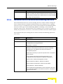
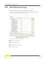
RADIUS Performance Page..................................................................................... 37
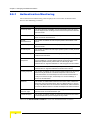
2.6.1
Authentication Monitoring ................................................................................. 38
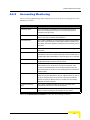
2.6.2
Accounting Monitoring ...................................................................................... 39
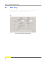
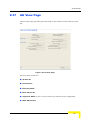
GPS Page .................................................................................................................. 40
2.7.1
Chain Configuration .......................................................................................... 41
2.7.2
BS Clock Parameters ....................................................................................... 43
2.7.3
GPS Info ........................................................................................................... 45
2.7.4
GPS Status ....................................................................................................... 46
Modular Base Station PF Parameters Page........................................................... 47
2.8.1
PF General Parameters.................................................................................... 48
2.8.2
PF Servers Table.............................................................................................. 48
Modular Base Station PF Performance Page ........................................................ 50
2.10 General Radio Parameters Page............................................................................. 52
2.11 Radio Clusters Page ................................................................................................ 55
2.12 Outdoor Units Page ................................................................................................. 57
2.13 Default Operational Settings Page ......................................................................... 60
2.14 Filters Page...............................................................................................................62
2.14.1 Interface Tab..................................................................................................... 62
2.14.2 L2 Tab............................................................................................................... 64
x
AlvariCRAFT User Manual
Contents
2.14.3 L3/L4 Tab.......................................................................................................... 66
2.15 MAC Deny List Page ................................................................................................ 68
2.16 Filtering Performance Page .................................................................................... 69
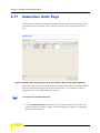
2.17 Subscriber Units Page............................................................................................. 70
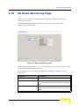
2.18 SU Radio Monitoring Page ...................................................................................... 73
2.19 Services Page........................................................................................................... 75
2.20 Subscribers Page..................................................................................................... 82
2.21 Service Profiles Page............................................................................................... 85
2.22 Forwarding Rules Page ........................................................................................... 92
2.23 Priority Classifiers Page.......................................................................................... 96
2.24 QoS Profiles Page .................................................................................................... 99
2.25 Voice Domain Page................................................................................................ 102
2.26 Service Group Page ............................................................................................... 105
2.27 Licenses Page ........................................................................................................ 108
2.27.1 SUs License Bank Status Tab ........................................................................ 110
2.27.2 Base Station Licenses Tab ............................................................................. 111
2.27.3 Temporary Grace Licenses Tab ..................................................................... 112
2.27.4 Grace Licenses Tab........................................................................................ 113
2.28 License Upload Page ............................................................................................. 114
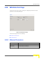
2.29 NPU View Page....................................................................................................... 115
2.30 NPU Data Port Page ............................................................................................... 117
2.30.1 Ethernet Parameters....................................................................................... 117
2.30.2 IP Parameters................................................................................................. 118
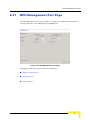
2.31 NPU Management Port Page................................................................................. 119
2.31.1 Ethernet Parameters....................................................................................... 120
2.31.2 IP Parameters................................................................................................. 120
AlvariCRAFT User Manual
xi
Contents
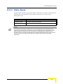
2.31.3 Static Route .................................................................................................... 121
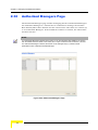
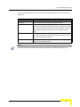
2.32 Authorized Managers Page ................................................................................... 122
2.33 Frequency Bands File Page .................................................................................. 124
2.34 NPU/Micro Base Station Unit Control Page......................................................... 126
2.34.1 Unit Control..................................................................................................... 127
2.34.2 Default Settings .............................................................................................. 128
2.34.3 Files in NPU/MBS ........................................................................................... 128
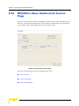
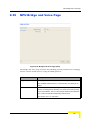
2.35 NPU Bridge and Voice Page.................................................................................. 129
2.36 NPU Performance Page ......................................................................................... 130
2.36.1 Data Port Rx Counters.................................................................................... 131
2.36.2 Data Port Tx Counters .................................................................................... 131
2.36.3 Management Port Counters............................................................................ 132
2.36.4 PF Server Counter.......................................................................................... 132
2.37 AU View Page ......................................................................................................... 133
2.38 Voice Parameters Page ......................................................................................... 135
2.39 Channels Page ....................................................................................................... 136
2.40 Air Interface Page................................................................................................... 140
2.40.1 MAC Parameters ............................................................................................ 141
2.40.2 Cell Radius ..................................................................................................... 141
2.40.3 Phy Parameters .............................................................................................. 142
2.40.4 ATPC Parameters........................................................................................... 142
2.40.5 Multi Rate Parameters .................................................................................... 142
2.40.6 Subchannelization .......................................................................................... 144
2.41 Spectrum Analyzer Page ....................................................................................... 145
2.42 AU Unit Control Page............................................................................................. 148
2.42.1 Unit Control..................................................................................................... 149
xii
AlvariCRAFT User Manual
Contents
2.42.2 SW Version Control ........................................................................................ 149
2.42.3 Default Settings .............................................................................................. 150
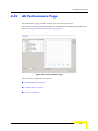
2.43 AU Performance Page ........................................................................................... 151
2.43.1 AU Backplane Counters ................................................................................. 152
2.43.2 AU Wireless Counters .................................................................................... 152
2.43.3 Voice Parameters ........................................................................................... 152
2.44 Modular Base Station Software Upgrade Page ................................................... 153
2.44.1 NPU & AU Section.......................................................................................... 154
2.44.2 SU Section...................................................................................................... 155
2.44.3 Settings Section.............................................................................................. 155
2.45 Modular Base Station Software Upgrade Settings Page.................................... 158
2.45.1 BS Tab............................................................................................................ 158
2.45.2 Sector Tab ...................................................................................................... 161
2.45.3 SU Tab............................................................................................................ 163
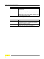
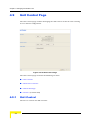
2.46 Backup Configuration Page .................................................................................. 165
2.47 Frequency Bands Upload...................................................................................... 167
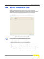
Chapter 3 - Managing a Micro Base Station
3.1
Introduction to Micro Base Station Management ............................................... 170
3.2
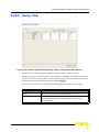
MBS (Micro Base Station) View Page................................................................... 172
3.2.1
Micro Base Station View................................................................................. 172
3.2.2
Outdoor Units View......................................................................................... 173
3.2.3
Radio Clusters View ....................................................................................... 173
3.3
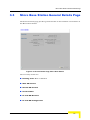
Micro Base Station General Details Page ............................................................ 175
3.4
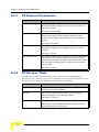
Micro Base Station PF Parameters Page ............................................................. 177
3.4.1
PF General Parameters.................................................................................. 178
AlvariCRAFT User Manual
xiii
Contents
3.4.2
PF Servers Table............................................................................................ 178
3.5
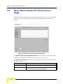
Micro Base Station PF Performance Page........................................................... 180
3.6
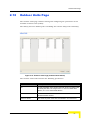
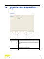
Micro Base Station Bridge and Voice Page......................................................... 182
3.7
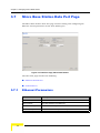
Micro Base Station Data Port Page ...................................................................... 184
3.7.1
Ethernet Parameters....................................................................................... 184
3.7.2
IP Parameters................................................................................................. 185
3.8
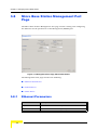
Micro Base Station Management Port Page ........................................................ 186
3.8.1
Ethernet Parameters....................................................................................... 186
3.8.2
IP Parameters................................................................................................. 187
3.8.3
Static Route .................................................................................................... 188
3.9
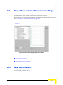
Micro Base Station Performance Page ................................................................ 189
3.9.1
Data Port Counters ......................................................................................... 189
3.9.2
Management Port Counters............................................................................ 190
3.9.3
Wireless Counters .......................................................................................... 190
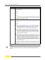
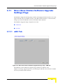
3.10 Micro Base Station Software Upgrade Page ....................................................... 192
3.10.1 MBS Section ................................................................................................... 193
3.10.2 SU Section...................................................................................................... 194
3.10.3 Settings Section.............................................................................................. 194
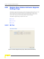
3.11 Micro Base Station Software Upgrade Settings Page ........................................ 197
3.11.1 mBS Tab......................................................................................................... 197
3.11.2 SU Tab............................................................................................................ 199
xiv
AlvariCRAFT User Manual
Contents
Chapter 4 - Managing a Subscriber Unit
4.1
Introduction to Subscriber Unit Management ..................................................... 202
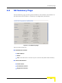
4.2
SU Summary Page ................................................................................................. 203
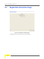
4.3
Registration Parameters Page .............................................................................. 206
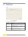
4.4
Bridging Page......................................................................................................... 208
4.5
Air Interface Page................................................................................................... 210
4.5.1
ATPC Parameters........................................................................................... 211
4.5.2
Multi Rate Parameters .................................................................................... 211
4.5.3
MAC Parameters (Standard Mode) ................................................................ 213
4.5.4
Phy Parameters (Standard Mode) .................................................................. 213
4.6
Frequency Scanning Page .................................................................................... 214
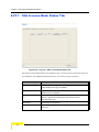
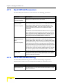
4.7
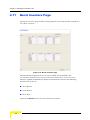
Best BST/AU Selection Page ................................................................................ 216
4.7.1
Best BST/AU Parameters ............................................................................... 218
4.7.2
Best BST/AU Monitoring................................................................................. 218
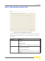
4.8
Gateways Page....................................................................................................... 220
4.9
Unit Control Page................................................................................................... 222
4.9.1
Unit Control..................................................................................................... 222
4.9.2
SW Version Control ........................................................................................ 223
4.9.3
Default Settings .............................................................................................. 224
4.9.4
License ........................................................................................................... 224
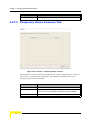
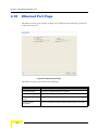
4.10 Ethernet Port Page................................................................................................. 226
4.11 Burst Counters Page ............................................................................................. 228
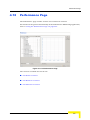
4.12 Performance Page.................................................................................................. 229
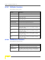
4.12.1 SU Radio Counters......................................................................................... 230
4.12.2 SU Wireless Counters .................................................................................... 230
4.12.3 SU Ethernet Counters..................................................................................... 231
AlvariCRAFT User Manual
xv
Contents
Chapter 5 - Using the Performance Page
5.1
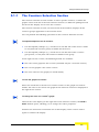
Using the Performance Page ................................................................................ 234
5.1.1
The Counters Selection Section ..................................................................... 235
5.1.2
The Graph and Controls Section .................................................................... 236
Chapter 6 - Parameters Summary
6.1
xvi
Parameters Summary ............................................................................................ 240
AlvariCRAFT User Manual
Figures
Figure 1-1: The Main Window ....................................................................................................... 3
Figure 1-2: Equipment Type Selection .......................................................................................... 4
Figure 1-3: The Equipment Editor ................................................................................................. 5
Figure 1-4: Range Discovery Window........................................................................................... 7
Figure 1-5: The Device Manager Window..................................................................................... 9
Figure 1-6: Help Navigator Window (Left) and Help Topic Window (Right) ................................ 13
Figure 1-7: Contents Tab ............................................................................................................ 15
Figure 1-8: Index Tab .................................................................................................................. 16
Figure 2-1: BS View Page ........................................................................................................... 22
Figure 2-2: General Management Parameters Page (modular Base Station) ............................ 25
Figure 2-3: Traps Control Page................................................................................................... 31
Figure 2-4: RADIUS Client Page, Ethernet CS Switching Mode................................................. 33
Figure 2-5: RADIUS Client Page, IP CS Switching Mode ........................................................... 34
Figure 2-6: RADIUS Performance Page ..................................................................................... 37
Figure 2-7: GPS Page (Micro Base Station) ............................................................................... 40
Figure 2-8: GPS Page (modular Base Station) ........................................................................... 41
Figure 2-9: Modular Base Station PF Parameters Page ............................................................. 47
Figure 2-10: Modular Base Station PF Performance Page ......................................................... 50
Figure 2-11: General Radio Parameters Page............................................................................ 52
Figure 2-12: Radio Clusters Page (modular Base Station) ......................................................... 55
Figure 2-13: Outdoor Units Page (modular Base Station)........................................................... 57
Figure 2-14: Default Operational Settings Page (modular Base Station, Ethernet CS Switching
Mode) .......................................................................................................................................... 60
Figure 2-15: Filters Page - Interface Tab .................................................................................... 63
Figure 2-16: Filters Page - L2 Tab .............................................................................................. 64
Figure 2-17: Filters Page - L3/L4 Tab ......................................................................................... 66
Figure 2-18: MAC Deny List Page............................................................................................... 68
Figure 2-19: Filtering - Performance Page .................................................................................. 69
Figure 2-20: Subscriber Units Page (modular Base Station, Ethernet CS Switching Mode) ...... 70
Figure 2-21: SU Radio Monitoring Page ..................................................................................... 73
Figure 2-22: Services Page, Ethernet CS Switching Mode......................................................... 75
Figure 2-23: Services Page, IP CS Switching Mode ................................................................... 76
Figure 2-24: Subscribers Page.................................................................................................... 82
Figure 2-25: Service Profiles Page, Ethernet CS Switching Mode.............................................. 85
Figure 2-26: Service Profiles Page, IP CS Switching Mode........................................................ 86
Figure 2-27: Forwarding Rules Page, Ethernet CS Switching Mode .......................................... 92
Figure 2-28: Priority Classifiers Page.......................................................................................... 96
Figure 2-29: QoS Profiles Page .................................................................................................. 99
Figure 2-30: Voice Domain Page .............................................................................................. 102
Figure 2-31: Service Group Page.............................................................................................. 105
Figure 2-32: Licenses - SUs License Bank Status Tab............................................................. 110
Figure 2-33: Licenses - Base Station Licenses Tab.................................................................. 111
Figure 2-34: Licenses - Temporary Grace Licenses ................................................................. 112
Figure 2-35: Licenses - Grace Licenses Tab ............................................................................ 113
Figure 2-36: License Upload Page............................................................................................ 114
Figure 2-37: NPU View Page .................................................................................................... 115
Figure 2-38: NPU Data Port Page............................................................................................. 117
Figure 2-39: NPU Management Port Page ............................................................................... 119
Figure 2-40: Authorized Managers Page .................................................................................. 122
Figure 2-41: Frequency Bands File Page.................................................................................. 124
Figure 2-42: NPU Unit Control Page ......................................................................................... 126
Figure 2-43: Bridge and Voice Page (NPU) .............................................................................. 129
Figure 2-44: NPU Performance Page ....................................................................................... 130
Figure 2-45: AU View Page....................................................................................................... 133
Figure 2-46: Voice Parameters Page ........................................................................................ 135
Figure 2-47: Channels Page ..................................................................................................... 136
Figure 2-48: AU Air Interface Page ........................................................................................... 140
xviii
AlvariCRAFT User Manual
Figure 2-49: Spectrum Analyzer Page ...................................................................................... 145
Figure 2-50: AU Unit Control Page............................................................................................ 148
Figure 2-51: AU Performance Page .......................................................................................... 151
Figure 2-52: Software Upgrade Page (modular Base Station).................................................. 154
Figure 2-53: Software Upgrade Settings Page - BS Tab (modular Base Station)..................... 158
Figure 2-54: Software Upgrade Settings Page - Sectors Tab (modular Base Station) ............. 161
Figure 2-55: Software Upgrade Settings Page - SU Tab (modular Base Station) .................... 163
Figure 2-56: Backup Configuration Page .................................................................................. 165
Figure 2-57: Frequency Bands Upload Page ............................................................................ 167
Figure 3-1: MBS (Micro Base Station) View Page .................................................................... 172
Figure 3-2: General Details Page, Micro Base Station.............................................................. 175
Figure 3-3: PF Parameters Page, Micro Base Station .............................................................. 177
Figure 3-4: PF Performance Pag, Micro Base Statione ............................................................ 180
Figure 3-5: Bridge and Voice Page, Micro Base Station ........................................................... 182
Figure 3-6: Data Port Page, Micro Base Station ....................................................................... 184
Figure 3-7: Management Port Page, Micro Base Station.......................................................... 186
Figure 3-8: Performance Page, Micro Base Station.................................................................. 189
Figure 3-9: Micro Base Station Software Upgrade Page .......................................................... 193
Figure 3-10: Micro Base Station Software Upgrade Settings Page - mBS Tab ........................ 197
Figure 3-11: Micro Base Station Software Upgrade Settings Page - SU Tab ........................... 199
Figure 4-1: SU Summary Page ................................................................................................. 203
Figure 4-2: Registration Parameters Page................................................................................ 206
Figure 4-3: Bridging Page ......................................................................................................... 208
Figure 4-4: SU Air Interface Page (3.5 GHz Unit) ..................................................................... 210
Figure 4-5: Frequency Scanning Page...................................................................................... 214
Figure 4-6: Best BST/AU Selection Page.................................................................................. 217
Figure 4-7: Gateways Page ...................................................................................................... 220
Figure 4-8: SU Unit Control Page.............................................................................................. 222
Figure 4-9: Ethernet Port Page ................................................................................................. 226
Figure 4-10: Burst Counters Page............................................................................................. 228
AlvariCRAFT User Manual
xix
Figure 4-11: SU Performance Page .......................................................................................... 229
Figure 5-1: Performance Page .................................................................................................. 234
xx
AlvariCRAFT User Manual
1
Chapter 1 - Using AlvariCRAFT
In This Chapter:
“Installing AlvariCRAFT” on page 2
“Getting Started” on page 3
“Using the Device Manager” on page 9
“How to Get Help” on page 13
Chapter 1 - Using AlvariCRAFT
1.1
Installing AlvariCRAFT
The executable AlvariCRAFT file (Install_<version number>.exe) is available in the
CD package.
Run the executable file and follow the instructions to install the AlvariCRAFT
utility with the BreezeMAX Device Manager on your PC.
NOTE
Installing AlvariCRAFT will automatically uninstall a previously installed version of AlvariCRAFT.
When a previous version is uninstalled automatically, the list of managable devices that is kept as a
part of AlvariCRAFT will be deleted.
The AlvariCRAFT application must be closed before starting installation of a new version.
2
AlvariCRAFT User Manual
Getting Started
1.2
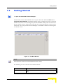
Getting Started
To open the AlvariCRAFT Device Manager:
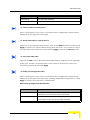
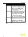
Double-click on the AlvariCRAFT icon or open it from the windows Start menu
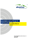
(Programs>AlvariCRAFT). The Main window opens, enabling view the current list
of the devices that can be managed by the AlvariCRAFT utility, add new devices to
the list, delete devices from the list and edit the relevant properties of the devices
in the list. You can open the Device Manager or establish a Telnet cut-through to
a selected device.
Figure 1-1: The Main Window
NOTE
When opened for the first time, the Managed Devices list is empty.
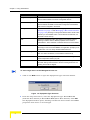
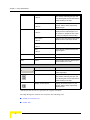
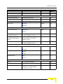
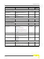
The following are the controls on the Main window:
Button
Description
New
Adds a new device to the list of devices that can be managed by the
utility.
AlvariCRAFT User Manual
3
Chapter 1 - Using AlvariCRAFT
Button
Description
Range Discovery
Initiates a search for devices in a configurable range. Discovered
devices will be added to the list of manageable devices.
Test Connectivity
Tests connectivity with selected device(s) and displays for each
device whether the SNMP communities configured in AlvariCRAFT
match those configured in the device.
Configure
Opens the Device Manager (see “Managing a Modular Base
Station” on page 19 and “Managing a Micro Base Station”
on page 169), allowing to manage the selected device and the SUs
served by it. Not available if two or more devices are selected, or if
the State is other than Up.
Edit
Opens the Equipment Editor (see below) for the selected device,
allowing to edit the device’s SNMP properties and its name in
AlvariCRAFT. The IP Address of a defined device cannot be editted.
Delete
Deletes the selected device(s) from the database. Select the
device(s) to remove and click Delete. The application prompts you for
confirmation. You can always redefine deleted devices.
Telnet Cut Through
Opens a Telnet session to the selected device. Not available if more
than one device is selected, or if the State is other than Up.
Export
Exports the list of managed devices with the relevant setting to a
Comma Separated Values (csv) file.
Import
Imports a Comma Separated Values (csv) file with managed devices
and their settings and add them to the list of managed devices. An
existing device will be skipped.
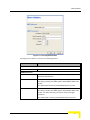
To add a single device to the Managed Devices list:
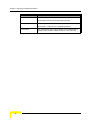
1
Click on the New button to open the Equipment Type selection window.
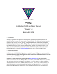
Figure 1-2: Equipment Type Selection
2
From the drop-down menu, select the Equipment Type: BreezeMAX BS
(modular Base Station) or BreezeMAX MBS (Micro Base Station). Click OK.
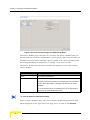
The Equipment Editor opens, allowing to define the Device Name and SNMP
properties of the device to be managed.
4
AlvariCRAFT User Manual
Getting Started
Figure 1-3: The Equipment Editor
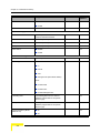
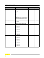
The Equipment Editor includes the following fields:
Parameter
Description
NMS Reference
Device Name
The device’s name in the AlvariCRAFT utility.
SNMP Parameters
IP Address
The device’s IP Address. Read-only when editing the properties of a
previously defined device.
Read community
The Read community string (password) for SNMP get operations.
This string is used by the SNMP agent to allow/disallow SNMP read
access.
The default Read Community in BreezeMAX devices is public.
Write community
The Write community string (password) for SNMP set operations.
This string is used by the SNMP agent to allow/disallow SNMP write
access. The Write community can also be used for read (get)
operations.
The default Write Community in BreezeMAX devices is private.
AlvariCRAFT User Manual
5
Chapter 1 - Using AlvariCRAFT
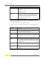
Parameter
Description
Retries
The maximum number of retries for SNMP/TFTP communication with
the Device.
The range is from 0 to 255.
The default is 2 retries.
Timeout(s)
The maximum time in seconds that the requesting process waits for a
response from the Device before attempting a retransmission (or
aborting if the maximum number of retries has been reached).
The available range is 1 to 3600 seconds.
The default is 15 seconds.
3
Enter the Device Name (optional), IP Address, Read community and Write
community. Click OK.
4
The device’s is added to the Managed Devices list.
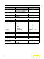
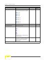
For each defined device, the following information is displayed in the Managed
Devices list:
6
Parameter
Description
Name
The name of the device as defined in the Equipment Editor (may differ
from the Device Name defined in the device).
Type
The type of device: BreezeMAX BS or BreezeMAX MBS.
Running SW Ver
The running software version of the device (in a modular Base Station
this is the SW version of the NPU). Displayed only after connecting with
the device.
IP Address
The IP address of the device (the port used for accessing the device).
State
The connection state of the device: Up if AlvariCRAFT can communicate
with it, Unreachable for a device that was reached in the past but cannot
be reached currently, or Unknown for a device that was never reached by
the AlvariCRAFT utility.
Serial Number
The serial number of the device (in a modulatr Base Station, this is the
serial number of the NPU card). Displayed only after connecting with the
device.
Switching Mode
The current Switching Mode of the device: Ethernet CS or IP CS (in the
current release IP CS Switching Mode is applicable only for a modular
Base Station).
AlvariCRAFT User Manual
Getting Started
NOTE
If the Authorized Managers list in the device is not empty, the AlvariCRAFT station must be defined
as an Authorized Manager.
Configuring wrong communities during the initial definition of the device in the Equipment Editor will
cause the device’s State to be presented as Unknown or Unreacheable.
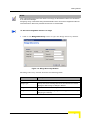
To discover manageable devices in a range:
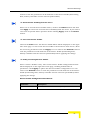
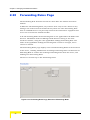
1
Click on the Range Discovery button to open the Range Discovery window.
Figure 1-4: Range Discovery Window
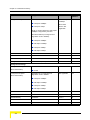
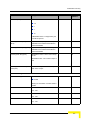
The Range Discovery window includes the following fields:
Parameter
Description
General
Range Type
A drop-down menu enabling selection of the method to be used for
efining the search range: IP Range or Subnet.
Range Start
The start IP address of the range/subnet.
Range End/Subnet Mask
The end IP address (if Range Type is IP Range) or subnet mask (if
Range Type is Subnet).
SNMP Parameters
AlvariCRAFT User Manual
7
Chapter 1 - Using AlvariCRAFT
Parameter
Description
Retries
The maximum number of retries for SNMP/TFTP communication with
each device in the defined range.
The range is from 0 to 255.
The default is 2 retries.
Timeout(s)
The maximum time in seconds that the requesting process waits for a
response from a device before attempting a retransmission (or
aborting if the maximum number of retries has been reached).
The available range is 1 to 3600 seconds.
The default is 15 seconds.
Read community
The Read community string (password) for SNMP get operations.
This string is used by the SNMP agent to allow/disallow SNMP read
access.
The default Read Community in BreezeMAX devices is public.
Write community
The Write community string (password) for SNMP set operations.
This string is used by the SNMP agent to allow/disallow SNMP write
access. The Write community can also be used for read (get)
operations.
The default Write Community in BreezeMAX devices is private.
2
Select the Range Type and enter the IP parameters. Enter the SNMP
communities and update the Retries and Timeout parameters if necessary.
Click OK.
3
The Range Discovery Runtime Results window opens, displaying the search
progress and the discovery results for each IP address in the defined range.
You may abort the search before it is fully completed by clicking on the Cancel
button. After viewing the results click on the Close button.
4
The discovered devices are added automatically to the Managed Devices list.
To manage a device:
Double-click on the selected entry in the Managed Devices list, or select it and
click on the Configure button. The Device Manager for the selected entity opens,
displaying the main page for the device.
8
AlvariCRAFT User Manual
Using the Device Manager
1.3
Using the Device Manager
This section includes:
“The Device Manager Components
“Common Control Buttons
“Hiding and Displaying the Navigation Pane
“Working with Tables
“Working with Configuration Tables
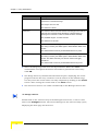
1.3.1
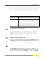
The Device Manager Components
Figure 1-5: The Device Manager Window
AlvariCRAFT User Manual
9
Chapter 1 - Using AlvariCRAFT
The Device Manager window comprises the following components:
1.3.2
Component
Description
Title Bar
Identifies the managed device's name. It also includes standard icons
for minimizing, maximizing or closing the Device Manager.
Navigation Pane
Displays all configuration/information pages and enables opening a
selected page by clicking on it.
Selected Page
The selected page. Enables viewing/managing the applicable
parameters.
Common Control Buttons
The following buttons are common to most configuration/information pages.
Button
Description
Updates the information displayed in the page according to current
values acquired from the device.
Implements the modifications to the configuration of the device.
Exiting the Device Manager or switching to another page without
applying opens a confirmation dialog box, enabling to decide whether
to discard the changes or continue editing.
This button is not available in information pages that display read-only
details and do not include any configurable parameters.
Help
1.3.3
Click on the Help button to open the Help Navigator, displaying the
Help topic for the current page.
Hiding and Displaying the Navigation Pane
By default, both the Navigation Pane and Work Area are displayed. When hovering
the mouse over the separation bar between the Navigation Pane and Work Area,
the mouse pointer becomes a double-headed arrow (↔). You can change the size
of the Navigation Pane by dragging this arrow left/right until reaching the
required display.
You can hide the Navigation Pane to increase the size of the Work Area or hide the
Work area to increase the size of the Navigation Pane by clicking on the
arrowheads (
10
) located on the separation bar.
AlvariCRAFT User Manual
Using the Device Manager
With the Navigation Pane hidden or maximized, if clicking the arrowhead does not
restore the display of both panes, manually drag the separation bar to restore the
display.
1.3.4
Working with Tables
Most of AlvariCRAFT tables and lists allow sorting, resizing and rearranging the
column display sequence.
To sort a table:
Tables can be sorted in an ascending order by clicking on any of the column
headings. Click again on the column heading to sort in a descending order. Click
a third time to return to no sorting (default mode).
To resize columns:
To resize a column, position the cursor on the border line between two columns
headings. The cursor changes into a double-headed arrow. Drag the cursor to the
left or to the right to increase or decrease the size of a column.
To rearrange columns:
To rearrange the columns sequence, click a column header and drag it to the new
desired position.
1.3.5
Working with Configuration Tables
In some pages, tables are used for displaying information and configuring or
managing multiple entities of the same type.
Grayed-out cells are read-only.
To modify the configuration of an existing entity:
Double-click on the applicable cell: In a text-cell, edit the content. In some cells a
drop-down menu will open, enabling selection of the required option. Click on any
other cell to apply the change to the selected cell. At this stage the change is
AlvariCRAFT User Manual
11
Chapter 1 - Using AlvariCRAFT
applied only to the display. The change is applied to the device only after clicking
on the Apply button.
In rows with modified parameter(s) all the details are colored blue.
The following Row Control buttons are available in most pages with tables:
12
Button
Description
Delete
Select a row, click on the Delete button and then on the Apply button
to remove the selected entity from the device. The details of a deleted
entry are colored red.
Revert
Select one or more rows and click on the Revert button to cancel all
changes made in these rows that were not applied yet. This applies
also to entities that were selected for deletion.
Add
Click on the Add button to add a new entity (if applicable). The new
entry will be colored green.
AlvariCRAFT User Manual
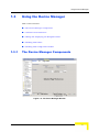
How to Get Help
1.4
How to Get Help
Click the Help button
to open the Help Navigator window and the Help Topic
window for a specific window.
Figure 1-6: Help Navigator Window (Left) and Help Topic Window (Right)
NOTE
The Help Navigator Window and Help Topic Window displayed above are examples. The displayed
content is not applicable for this version of AlvariCRAFT.
1.4.1
The Help Navigator
The Help Navigator window enables to view help contents, select a specific subject
or search for information.
The Help Navigator window includes the following items:
Menus
Menu
AlvariCRAFT User Manual
Sub-Menu*
Description
13
Chapter 1 - Using AlvariCRAFT
File
Display
<Ctrl-D>
Display in New Window
<Ctrl-W>
Print Tree
<Ctrl-R>
Print Topics
<Ctrl-S>
Close
Opens the selected topic in the Help
Topic window. Selecting the topic and
then selecting this menu is equivalent to
double-clicking on the topic.
Displays the selected topic in a new
window, without closing a previously
displayed topic.
Enables to print the topics tree as
displayed on the Help Navigator. You
can expand or collapse the tree nodes
to change the display before printing.
Enables to print the selected topic that is
displayed on the Help Topic window.
Closes the Help Navigator window.
<Ctrl-O>
Exit
<Ctrl-X>
View
Help
Closes all help windows and exits the
Help Navigator.
Contents
Displays the Contents tab.
Index
Displays the Index tab.
About
Opens the About window, displaying the
version details for the Help.
Tooltip
Description
Toolbar
Icon
Enables to select the major topics for
online help display.
Display
Opens the selected topic in the Help
Topic window. Selecting the topic and
then selecting this menu is equivalent to
double-clicking on the topic.
Display in New Window
Displays the selected topic in a new
window, without closing a previously
displayed topic.
* The keyboard shortcut is provided in angular brackets.
The Help Navigator window also includes the following tabs:
“Table of Contents Tab
“Index Tab
14
AlvariCRAFT User Manual
How to Get Help
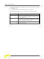
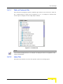
1.4.1.1
Table of Contents Tab
The Contents tab displays all the available topic nodes in tree structure. Click on
the + symbol next to a topic node to expand it, or on -, to collapse it. Double-click
on the topic to display it in the Help Topic window.
Figure 1-7: Contents Tab
NOTE
The Contents Tab displayed above is an examples. The displayed content is not applicable for this
version of AlvariCRAFT.
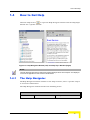
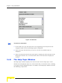
1.4.1.2
Index Tab
The Index tab enables to search for specific content in all help topics.
AlvariCRAFT User Manual
15
Chapter 1 - Using AlvariCRAFT
Figure 1-8: Index Tab
To search for information:
1
In the Index tab, type the keywords or the beginning of the keyword in the
designated field. A list of matching topics is displayed.
2
Select the topic that matches your query. The list of available topics is
displayed.
3
Select an item from the list and click Open to display the selected topic in the
Help Topic window. You can also double-click on the list item to display its
content.
1.4.2
The Help Topic Window
The Help Topic window displays the content of the selected help topic. At the
bottom of each displayed topic are a back arrow and/or a forward arrow, enabling
to navigate between displayed topics. In addition, the Help Topic window includes
the following components:
16
AlvariCRAFT User Manual
How to Get Help
Menus
Menu
Sub-Menu*
Description
File
Print Topic
Enables to print the selected topic on the active Help
Topic window.
<Ctrl+P>
Close
Closes the Help Topic window.
<Ctrl+O>
Exit
Closes all help windows and exits the Help Navigator.
<Ctrl+X>
Go
Back
<Alt-Left>
Forward
Tools
Displays the previous topic. When the first topic is
displayed, this menu item is greyed out (unavailable
for selection). Click Alt and the left arrow on your
keyboard to display previous topics.
<Alt-Right>
Displays the next topic. When the last topic is
displayed, this menu item is greyed out (unavailable
for selection). Click Alt and the right arrow on your
keyboard to display the next topics.
Navigator
Activates/opens the navigator window.
Find
Enables to search for text on the active topic.
<Ctrl-F>
Dock/Undock
<Ctrl-K>/<Ctrl-U>
Merges/separates the Help Navigator and Help Topic
windows. When docked, a single menu bar displays
all available menus (File, View, Go, Tools, Help).
Toolbar
Icon
AlvariCRAFT User Manual
Tooltip
Description
Navigator
Activates/opens the navigator window.
Back
Displays the previous topic. When the first topic is
displayed, this menu item is greyed out (unavailable
for selection). Click Alt and the left arrow on your
keyboard to display previous topics.
Forward
Displays the next topic. When the last topic is
displayed, this menu item is greyed out (unavailable
for selection). Click Alt and the right arrow on your
keyboard to display the next topics.
Print Topic
Enables to print the selected topic on the active Help
Topic window.
17
Chapter 1 - Using AlvariCRAFT
18
Dock
Merges the Help Navigator and Help Topic windows.
When docked, a single menu bar displays all
available menus (File, View, Go, Tools, Help).
Undock
Separates the docked Help Navigator and Help Topic
windows.
AlvariCRAFT User Manual
2
Chapter 2 - Managing a Modular Base
Station
Chapter 2 - Managing a Modular Base Station
2.1
Introduction to Modular Base Station
Management
The tree menu in the Navigation Pane on the left side of the Device Manager
window enables selecting the following view and configuration pages:
“BS View Page” on page 22
" “General Management Parameters Page” on page 25
" “Traps Control Page” on page 31
" “RADIUS Client Page” on page 33
" “RADIUS Performance Page” on page 37
" “GPS Page” on page 40
" “Modular Base Station PF Parameters Page” on page 47
" “Modular Base Station PF Performance Page” on page 50
" “General Radio Parameters Page” on page 52
" “Radio Clusters Page” on page 55
" “Outdoor Units Page” on page 57
" “Default Operational Settings Page” on page 60
"
Filtering:
" “Filters Page” on page 62
" “MAC Deny List Page” on page 68
" “Filtering Performance Page” on page 69
" “Subscriber Units Page” on page 70
" “SU Radio Monitoring Page” on page 73
" Services:
" “Services Page” on page 75
" “Subscribers Page” on page 82
" “Service Profiles Page” on page 85
20
AlvariCRAFT User Manual
Introduction to Modular Base Station Management
" “Forwarding Rules Page” on page 92
" “Priority Classifiers Page” on page 96
" “QoS Profiles Page” on page 99
" “Voice Domain Page” on page 102
" “Service Group Page” on page 105
" “Licenses Page” on page 108
" “License Upload Page” on page 114
" NPU: “NPU View Page” on page 115
" “NPU Data Port Page” on page 117
" “NPU Management Port Page” on page 119
" “Authorized Managers Page” on page 122
" “Frequency Bands File Page” on page 124
" “NPU/Micro Base Station Unit Control Page” on page 126
" “NPU Bridge and Voice Page” on page 129
" “NPU Performance Page” on page 130
" AU Slot 1-4, 7-9: “AU View Page” on page 133
" “Voice Parameters Page” on page 135
" “Channels Page” on page 136
" “Air Interface Page” on page 140
" “Spectrum Analyzer Page” on page 145
" “AU Unit Control Page” on page 148
" “AU Performance Page” on page 151
" Software:
" “Modular Base Station Software Upgrade Page” on page 153
" “Modular Base Station Software Upgrade Settings Page” on page 158
" “Backup Configuration Page” on page 165
" “Frequency Bands Upload” on page 167
AlvariCRAFT User Manual
21
Chapter 2 - Managing a Modular Base Station
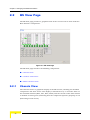
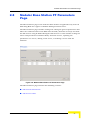
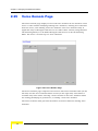
2.2
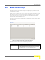
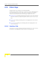
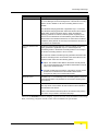
BS View Page
The BS View page provides a graphical view of the current status of the modular
Base Station’s components.
Figure 2-1: BS View Page
The BS View page includes the following components:
“Chassis View”
“Outdoor Units View”
“Radio Clusters View”
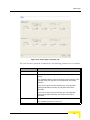
2.2.1
Chassis View
The Chassis View is a graphical display of the BS chassis, showing the installed
components and their status. The display is refreshed every 15 seconds. Each of
the installed modules (NPU, AUs, PIUs, PSUs) and the 10 fans of the AVU module
is marked in either green (indicating that the component operates properly) or red
(indicating a fault status).
22
AlvariCRAFT User Manual
BS View Page
For a High-Power PIU, the letters “HP” are displayed at the bottom (in the area
that should be marked green). In addition, you can place the cursor on the PIU to
get a tooltip indicating its type (Normal Power/High Power). The left LED indicator
on the top side of the PIU indicates its status: green for Master, grey for
Redundant (applicable only if two PIUs are installed and connected to power).
For the NPU and installed AU(s), additional information and actions are available:
The DATA and MGMT ports of the NPU are marked either green or red,
indicating the Ethernet link status (up or down).
The GPS Status indicator on the NPU is green when at least 4 satellites are
received. Otherwise it is grey.
Double-click on the NPU module to open the NPU general view page.
Double-click on the DATA port to open the DATA Port configuration page.
Double-click on the MGMT port to open the Management Port configuration
page.
In an AU, each of the ODU connectors (channels) are marked as follows:
" No marking (gray): The Admin Status is Disabled.
" Green: The Operational Status is Up, the Admin Status is Enabled.
" Red: The Operational Status is Down (fault, the Admin Status is Enabled).
Place the cursor on a connector to view the Downlink Frequency.
Click once on an ODU connector (channel) to view relevant associations: A
blue background will be added to the selected channel as well as to the
Outdoor Unit and Radio Cluster associated with it (if applicable).
Double-click on any of the ODU connectors (channels) to open the Channels
configuration page for the applicable AU.
Double-click on an AU module to open the AU general view page for the
selected AU.
AlvariCRAFT User Manual
23
Chapter 2 - Managing a Modular Base Station
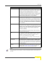
2.2.2
Outdoor Units View
The Outdoor Units view shows the ODU icons all the 24 Outdoor Units that can
be defined. An undefined ODU is marked in gray. A defined ODU is marked in
either green or red, indicating its operational status. Note that the operational
status of an ODU can be OK (Up) only if it is properly connected to an active
channel. For all defined ODUs the configured Tx Power is displayed below the
unit’s icon.
Click on an ODU’s icon to view relevant associations: A blue background will be
added to the selected ODU as well as to the ODU connector (AU channel) and
Radio Cluster associated with it (if applicable).
Double-click on any of the ODUs to open the Outdoor Units configuration page.
Place the cursor on an ODU to view its configured Tx Power and Downlink
Frequency (applicable only if the ODU is configured).
2.2.3
Radio Clusters View
The Radio Clusters view shows text boxes for the 6 Radio Clusters that can be
defined. The name of a defined Radio Cluster is displayed in the relevant area.
Note that the name can also be an empty string (null). It is recommended to define
Radio Cluster Name for all defined Radio Cluster to provide clear distinction
between defined and not-defined Radio Cluster.
Click on a Radio Cluster’s text box to view relevant associations: A blue
background will be added to the selected Radio Cluster as well as to the ODU(s)
and AU channel(s) associated with it (if applicable).
Double-click on any of the Radio Clusters to open the Radio Clusters
configuration page.
24
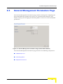
AlvariCRAFT User Manual
General Management Parameters Page
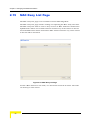
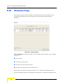
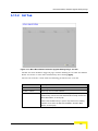
2.3
General Management Parameters Page
The General Management Parameters page enables viewing and configuring the
general identification details of the device. In a modular Base Station it also
enables viewing and changing the Switching Mode of the device and the PM/TM
parameters.
Figure 2-2: General Management Parameters Page (modular Base Station)
The General Management Parameters page includes the following components:
“SNMP Reference”
“Switching Mode”
“PM/TM Parameters”
AlvariCRAFT User Manual
25
Chapter 2 - Managing a Modular Base Station
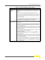
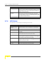
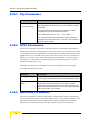
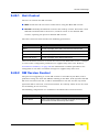
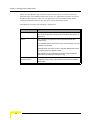
2.3.1
2.3.2
SNMP Reference
Parameter
Description
Sys Name
The system’s name. A string of up to 255 printable characters.
Sys Location
The system’s location. A string of up to 255 printable characters.
Sys Contact
The system’s contact person name. A string of up to 255 printable
characters.
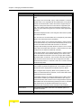
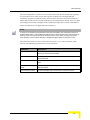
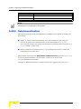
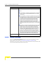
Switching Mode
NOTE
In the current release the Switching Mode parameter is applicable only for modular Base Stations. It
is not applicable to Micro Base Stations that operate always in Ethernet CS Switching Mode.
The Switching Mode parameter defines the convergence sublayer (CS) used in the
network infrastructure. Ethernet CS is applicable to the current generation of
layer 2 based services. IP CS Switching Mode is compatible with the infrastructure
of next generation WiMAX systems or DSL systems. IP CS Switching Mode
provides smooth upgrade to systems that fully support the IEEE 802.16e
standard, with the same “Look and Feel” of service provisioning. The operator will
only have to replace his access equipment while keeping most of his network
equipment unchanged. It also enables operators working with BRAS that
supports DHCP option 82 for already deployed DSL systems to add a wireless
access solution in areas where DSL is not available using the same provisioning
equipment.
A change in the Switching Mode is applied after resetting the NPU.
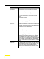
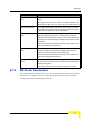
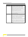
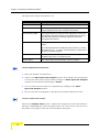
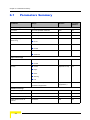
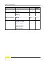
The following table lists the functional changes that are applied after switching to
IP CS Switching Mode. For more details on using the IP CS Switching Mode refer
to the System Manual.
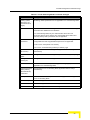
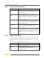
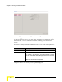
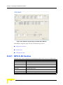
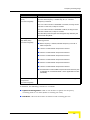
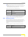
Table 2-1: IP CS Switching Mode Functional Changes
26
Parameter
Change Description
Default
Operational
Setting
The Default Operational Settings parameters are not applicable for IP CS
Switching Mode. The Service Working Mode is always Advanced Mode.
ServicesSubscribers
The Subscribers parameters are not applicable for IP CS Switching Mode.
AlvariCRAFT User Manual
General Management Parameters Page
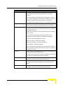
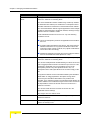
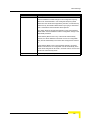
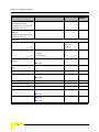
Table 2-1: IP CS Switching Mode Functional Changes
Parameter
Change Description
ServicesServices
All previous Ethernet CS Switching Mode Services are deleted from the
database.
Services can only be accepted from AAA server and are read-only.
A Service includes the following configurable parameters: Service Name,
Service Type, Service Profile Name, SU MAC Address, Service VPL ID (new
parameter that defines the VLAN ID to be used in the network side of the
NPU) and Admin Status.
The following parameters, used in Ethernet Switching Mode Services, are
not applicable for IP Switching Mode Services: Subscriber Name, VLAN List,
Hybrid VLAN Mode, VLAN Classification Mode, Access VLAN.
ServicesService Profiles
All previous Ethernet CS Switching Mode Service Profiles are deleted from
the database.
There are three new Service Types in IP CS Switching Mode: IP Mode Data,
IP Mode VoIP and IP Mode Managed VoIP (the previous L2, PPPoE and
VoIP Service Types used in Ethernet CS Switching Mode are not applicable
for IP CS Switching Mode).
Each Service Profile includes the following configurable parameters: Service
Type (IP Mode Data, IP Mode VoIP, IP Mode Managed VoIP), Service Profile
Name, Priority Classifier.
Maximum Number of Voice Calls configurable parameters is available only
for IP Mode Managed VoIP Service Profiles.
In IP Mode Managed VoIP service Profiles there is a new configurable
parameter, Voice Domain.
In IP Mode Data Service Profiles there is a new configurable parameter,
Service Group Name.
IP Mode VoIP and IP Mode Managed VoIP Service Profiles use the @@IP
Mode VoIP@@ Forwarding Rule (not available in the Service Profiles since
the name cannot be modified).
The following configurable parameters, used in Ethernet Switching Mode
Service Profiles, are not applicable for IP Switching Mode Service Profiles:
VLAN Transparency Mode, VPL ID, Priority Marking Mode, Priority Marking
Value, Forwarding Rule.
AlvariCRAFT User Manual
27
Chapter 2 - Managing a Modular Base Station
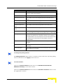
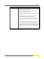
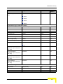
Table 2-1: IP CS Switching Mode Functional Changes
Parameter
Change Description
ServicesForwarding Rules
All previous Ethernet CS Switching Mode Forwarding Rules are deleted from
the database.
A single Forwarding Rule named @@IP Mode VoIP@@ with Service Type
IP Mode VoIP is provided for IP Mode VoIP and IP Mode Managed VoIP
Services. Certain parameters of this Forwarding Rule (except the Name and
Service Type) can be updated. This Forwarding Rule cannot be deleted. It is
not possible to define additional Forwarding Rules.
The default values of the @@IP Mode VoIP@@ Forwarding Rule
configurable parameters are:
Unicast Relaying: Enabled
Broadcast Relaying: Enabled
Unknown forwarding Policy: Forward
Multicast QoS Profile Name: @@IP Mode VoIP@@
ServicesPriority Classifiers
All previous Ethernet CS Switching Mode Priority Classifiers are deleted
from the database.
The Priority type is not configurable, and it is always DSCP (802.1p
prioritization is not available in IP CS Switching Mode).
ServicesQoS Profiles
All previous Ethernet CS Switching Mode QoS Profiles are deleted from the
database.
A single QoS Profile named @@IP Mode VoIP@@ is available as a default
for the Multicast QoS Profile in the @@IP Mode VoIP@@ Forwarding Rule.
All parameters of this QoS Profile can be updated, and it can also be deleted
from the database. Additional QoS Profiles can be defined.
The default values of the @@IP Mode VoIP@@ QoS Profile configurable
parameters are:
Name: @@IP Mode VoIP@@
QoS Type: BE
CT: Short (non-configurable)
MIR (Kbps): 128
Pre-configured
Profiles
28
The pre-configured profiles are not available in IP CS Switching Mode.
AlvariCRAFT User Manual
General Management Parameters Page
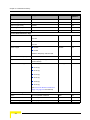
Table 2-1: IP CS Switching Mode Functional Changes
Parameter
Change Description
Filtering (Filters,
MAC Deny List
and Performance
pages)
All filtering related parameters are not applicable for IP CS Switching Mode.
RADIUS
All previous Ethernet CS Switching Mode Authentication and Accounting
parameters are deleted from the database.
In IP CS Switching Mode,only one Authentication Server and one
Accounting Server can be defined. The configurable Server Status and
read-only Activity Status parameters are not applicable.
DRAP related
parameters
DRAP is not used in IP CS Switching Mode. Hence, the following
configurable and read-only parameters/options are not applicable:
In NPU menu: Voice (DRAP TTL Retries)
In SU menu, Voice/Networking Gateways: Gateway Type
Operation Mode
(AU and SU)
Not applicable for IP CS Switching Mode (Operation Mode is always
Advanced Si)
SU Permanence
Status
Not applicable for IP CS Switching Mode (SU Status is always Temporary).
Adding and
Deleting SU,
Not applicable for IP CS Switching Mode.
Standard SW File
Standard AU/SU SW Files (Software Upgrade Settings page) are not
applicable for IP CS Switching Mode.
SU MAC (Standard
Mode) and Phy
(Standard Mode)
Parameters
Not applicable for IP CS Switching Mode (Operation Mode is always
Advanced Si).
Backup Files
The Profiles and Services option and the Filtering option are not applicable
for IP CS Switching Mode.
Service Groups
New feature-applicable for IP Mode Data Services
Voice Domains
New feature-applicable for IP Mode Managed VoIP Services
PF Servers
New feature-applicable for IP Mode Managed VoIP Services
AlvariCRAFT User Manual
29
Chapter 2 - Managing a Modular Base Station
2.3.3
PM/TM Parameters
NOTE
In the current release the PM/TM feature is applicable only for modular Base Stations. It is not
applicable for Micro Base Stations.
The PM/TM feature enable managing the collection of Performance Monitoring
and Traffic Monitoring data. When enabled, traffic (transferred data) information
and performance (link quality indicators) statistics are collected by the device and
stored in dedicated files that can be retrieved by the network management system
or any other external application, using TFTP. Whenever a new file is generated, a
suitable trap is sent. Analysis of the data can be used for various purposes such
as calculating capacity utilization and oversubscription, radio planning and
problem identification. Each file contains the accumulated traffic data and the per
SU performance statistics for a 15 minutes interval. For certain radio planning
purposes requiring higher resolution of performance statistics, it is possible to
request that the 15 minutes file will include also per SU performance statistics for
one minute intervals.
The PM/TM parameters are:
30
Parameter
Description
Status
Allows enabling or disabling the PM/TM feature.
Mode
Enables selection between Basic and Advanced modes of collecting
traffic data and performance statistics. In Basic mode, each file
contains all the relevant data for 15 minutes intervals, and up to the
last four files may be stored in the NPU. In Advanced mode each file
contains also performance statistics for 1 minute intervals, and the
NPU may store the last two files.
AlvariCRAFT User Manual
Traps Control Page
2.4
Traps Control Page
The Traps Control page enables viewing the current parameters of all traps and
modifying the parameters of selected traps. It also enables restoring the
configuration of all modified traps to their default values.
Figure 2-3: Traps Control Page
The Traps Control page includes a traps Status table that displays the following
properties for each trap:
Parameter
Description
ID
A read-only display of the trap’s Enterprise ID. Note that for standard
MIB II traps, the private enterprise IDs 128 to 132 are used instead of
the actual SNMP enterprise IDs 1 to 5.
Name
A read-only display of the trap’s name.
Admin Status
The Administrative Status of the trap. If the Admin Status is set to
Disable, this trap will not be sent by the managed device.
The available options are Enable and Disable.
AlvariCRAFT User Manual
31
Chapter 2 - Managing a Modular Base Station
Parameter
Description
Default Severity
A read-only display of the trap’s factory default severity level.
Current Severity
The current severity configured for the trap.
The available options are Critical, Major, Minor, Warning and Info.
Suppression Interval
The Suppression Interval is the minimum time between consecutive
transmissions of the same trap. This parameter can be used to
prevent excessive retransmissions of the same trap.
The available range is from 1 to 86,400 (seconds) or 0 for no
suppression.
For more information on the traps see the Traps and Alarms document.
NOTE
The table includes all BreezeMAX traps. Note that some of the traps are applicable only for one
device type: some traps are not applicable for a Micro Base Station, and some traps are not
applicable for a modular Base Station.
The Restore Defaults button at the top of the page, together with the drop-down
menu next to it, enables restoring all traps to their default configuration.
The available options in the drop-down menu and the respective effect on
configuration of all traps upon clicking on the Restore Defaults button are:
32
Option
Restore Defaults Operation
Admin Status
The Admin Status of all traps will be set to the default Admin Status of
Enable.
Severity
The Current Severity for each trap will revert to the default severity as
displayed in the Default Severity entry for the trap.
Suppression Interval
The Suppression Interval of all traps will be set to the default
Suppression Interval of 0 (no suppression).
All
All parameters of all traps will be set to their default values as defined
above.
AlvariCRAFT User Manual
RADIUS Client Page
2.5
RADIUS Client Page
The RADIUS page enables viewing and modifying the RADIUS parameters of the
device.
Figure 2-4: RADIUS Client Page, Ethernet CS Switching Mode
NOTE
Upon switching to IP CS Switching Mode, all previous Ethernet CS Switching Mode Authentication
and Accounting parameters are deleted from the database. Other changes that affect RADIUS
configuration in IP CS Switching Mode include:
a. Only one Authentication Server and one Accounting Server can be defined. The configurable
Server Status and read-only Activity Status parameters are not applicable.
b. The IP interface parameters for communicating with each of the servers are configurable
(alternatively, it is possible to automartically adopt the IP parameters of the Data port).
AlvariCRAFT User Manual
33
Chapter 2 - Managing a Modular Base Station
Figure 2-5: RADIUS Client Page, IP CS Switching Mode
The RADIUS Client Parameters page includes the following components:
“General Parameters”
“Authentication Servers/Accounting Servers”
2.5.1
General Parameters
The General Parameters section enables viewing and modifying parameters that
affect the communication with all RADIUS servers. These parameters include:
Parameter
Description
Retry Interval (sec)
The Retry Interval parameter defines the time in seconds to wait
before retransmitting a RADIUS message if no response is received.
The range is 1-5 (seconds).
Number Of Retries
The Maximum Number of Retries parameter defines the maximum
number of retransmission attempts, before a decision is taken to
revert to another server, if configured, or give up.
The range is 0-5 (retries).
34
AlvariCRAFT User Manual
RADIUS Client Page
Parameter
Description
Keep Alive Timeout (sec)
The device maintains a keep alive mechanism with all defined
servers. The Keep Alive Timeout defines the time in seconds to wait
before reaching a decision that a certain server is no longer available.
The range is 60-180 (seconds).
2.5.2
Authentication Servers/Accounting Servers
The Authentication Servers and Accounting Servers sections enable viewing the
status and parameters of defined Authentication/Accounting servers, adding a
new server (up to a maximum of two of each type in Ethernet CS Switching Mode,
and one of each type in IP CS Switching Mode), or deleting a server from the
database of the device. The parameters of an existing server cannot be updated: to
modify the parameters of a server, it must first be deleted and then defined again.
The Authentication/Accounting Servers tables include the following options for
each entry:
Parameter
Description
Server IP Address
The IP address of the server.
UDP Port
The UDP port number used by the RADIUS server for
authentication/accounting transactions.
Valid values: 1 to 65535.
Adopt Data Port
Applicable only in IP CS Switching Mode where the IP interface
defined for communication with the server may be on a different
subnet then the one defined for the Data port for data and
management purposes.
Double click on the entry to open the drop-down menu. The options
are Yes and No.
If Yes is selected then relevant interface parameters are not
configurable and will be adopted from Data port configuration:
Domain VLAN = Data Port Management VLAN ID
Domain Interface IP Address = Data Port IP Address
Domain Interface Subnet Mask = Data Port Subnet Mask
Domain Gateway = Data Port Gateway
If No is selected, these parameters must be configured. In this case
the IP parameters defined for the interface must be on a subnet that
is unique in the device
AlvariCRAFT User Manual
35
Chapter 2 - Managing a Modular Base Station
Parameter
Description
Domain VLAN
Applicable only in IP CS Switching Mode. Configurable only if Adopt
Data Port is set to No. The VLAN ID to be used for communication
with the server.
Available values for VLAN are 0 to 4094. Enter either null or 4095 for
No VLAN ID. 4095 will be displayed for No VLAN ID
36
Domain Interface IP
Address
Applicable only in IP CS Switching Mode. Configurable only if Adopt
Data Port is set to No. The interface IP address to be used for
communication with the server.
Domain Interface Subnet
Mask
Applicable only in IP CS Switching Mode. Configurable only if Adopt
Data Port is set to No. The subnet mask to be used with the interface
IP address for communication with the server.
Domain Gateway
Applicable only in IP CS Switching Mode. Configurable only if Adopt
Data Port is set to No. The default gateway IP address to be used for
communication with the server.
Oper Status
The Operational Status of the server: Up or Down (according to the
keep alive mechanism).
Status
Applicable only in Ethernet CS Switching Mode. The Activity Status of
the server: Active or Standby (indicates whether this is the server
currently in use for authentication/accounting purposes).
Is Primary
Applicable only in Ethernet CS Switching Mode. Defines whether this
server is Primary or Secondary. Each Authentication/Accounting
server can be defined as either Primary (checked) or Secondary
(un-checked). Only one Authentication/Accounting server can be
defined as Primary.
AlvariCRAFT User Manual
RADIUS Performance Page
2.6
RADIUS Performance Page
The RADIUS Performance page enables on-line view of selected counters.
Figure 2-6: RADIUS Performance Page
To change the Polling (automatic refresh) Interval:
Enter the required Polling Interval and click on the Apply button next to it. The
range for the polling interval is from 1 to 3,600 seconds.
The RADIUS page includes the following sections:
“Authentication Monitoring”
“Accounting Monitoring”
AlvariCRAFT User Manual
37
Chapter 2 - Managing a Modular Base Station
2.6.1
Authentication Monitoring
The Authentication Monitoring table displays for each of the Authentication
Servers the following counters:
Counter
Description
Round Trip Time
The time interval (in hundredths of a second) between the most recent
Access-Reply/Access-Challenge and the Access-Request that matched it
from this server.
Access Requests
The number of RADIUS Access-Request packets sent to this server. This
does not include retransmissions.
Access
Retransmissions
The number of RADIUS Access-Request packets retransmitted to this
server.
Access Accepts
The number of RADIUS Access-Accept packets (valid or invalid) received
from this server.
Access Rejects
The number of RADIUS Access-Reject packets (valid or invalid) received
from this server.
Access Challenges
The number of RADIUS Access-Challenge packets (valid or invalid)
received from this server.
Malformed Access
Responses
The number of malformed RADIUS Access-Response (Access-Accept,
Access-Challenge or Access-Reject) packets received from this server.
Malformed packets include packets with an invalid length. Bad
authenticators or Signature attributes or unknown types are not included.
Bad Authenticators
The number of RADIUS Access-Response packets containing invalid
authenticators or Signature attributes received from this server.
Pending Requests
The number of RADIUS Access-Request packets destined for this server
that have not yet timed out or received a response. This counter is
incremented when an Access-Request is sent and decremented due to
receipt of an Access-Accept, Access-Reject or Access-Challenge, a
timeout or retransmission.
Timeouts
The number of authentication timeouts to this server. After a timeout the
client may retry to the same server, send to a different server, or give up.
A retry to the same server is counted as a retransmit as well as a timeout.
A send to a different server is counted as a Request as well as a timeout.
Packets Of
Unknown Type
The number of RADIUS packets of unknown type which were received
from this server on the authentication port.
Packets Dropped
The number of RADIUS packets of which were received from this server
on the authentication port and dropped for any reason.
Click on the Reset Auth Counters to reset the Authentication Counters.
38
AlvariCRAFT User Manual
RADIUS Performance Page
2.6.2
Accounting Monitoring
The Accounting Monitoring table displays for each of the Accounting Servers the
following counters:
Counter
Description
Round Trip Time
The time interval (in hundredths of a second) between the most
recent Accounting-Response and the Accounting-Request that
matched it from this server.
Requests
The number of RADIUS Accounting-Request packets sent to this
server. This does not include retransmissions.
Retransmissions
The number of RADIUS Accounting-Request packets retransmitted to
this server. Retransmissions include retries where the Identifier and
Acct-Delay have been updated, as well as those in which they remain
the same.
Responses
The number of RADIUS packets received on the accounting port from
this server.
Malformed Responses
The number of malformed RADIUS Accounting-Response packets
received from this server. Malformed packets include packets with an
invalid length. Bad authenticators or unknown types are not included.
Bad Authenticators
The number of RADIUS Accounting-Response packets containing
invalid authenticators received from this server.
Pending Requests
The number of RADIUS Accounting-Request packets sent to this
server that have not yet timed out or received a response. This
counter is incremented when an Accounting-Request is sent and
decremented due to receipt of an Accounting-Response, a timeout or
retransmission.
Timeouts
The number of accounting timeouts to this server. After a timeout the
client may retry the same server, send to a different server, or give up.
A retry to the same server is counted as a retransmit as well as a
timeout. A send to a different server is counted as an AccountingRequest as well as a timeout.
Packets of Unknown
Type
The number of RADIUS packets of unknown type which were
received from this server on the accounting port.
Packets Dropped
The number of RADIUS packets of which were received from this
server on the accounting port and dropped for any reason.
Click on the Reset Acct Counters to reset the Accounting Counters.
AlvariCRAFT User Manual
39
Chapter 2 - Managing a Modular Base Station
2.7
GPS Page
The GPS page enables viewing and configuring the parameters that affect
inter-cell and intra-cell synchronization.
Figure 2-7: GPS Page (Micro Base Station)
40
AlvariCRAFT User Manual
GPS Page
Figure 2-8: GPS Page (modular Base Station)
The GPS page comprises the following sections:
“Chain Configuration”
“BS Clock Parameters”
“GPS Info”
“GPS Status”
2.7.1
Chain Configuration
The Chain Configuration section includes the following parameters:
AlvariCRAFT User Manual
41
Chapter 2 - Managing a Modular Base Station
Parameter
Description
Chain Number
(Current and Configured)
The Chain Number is used as a unique identifier of a chain. All
modular Base Stations or Micro Base Stations belonging to the same
chain should be configured with the same Chain Number. The Chain
Number can be used by a central management system to guarantee
that certain limitations are met. For example, in each chain one, and
only one device should be defined as Master.
In the current release, chaining is supported only in Micro Base
Stations.
The range is from 1 to 1500.
The default is 0, indicating that a Chain Number is not configured yet.
A valid Chain Number must be configured, and this number must be
unique in the system to properly support central management of
chaining.
GPS Protocol
(Current and Configured)
The GPS Protocol defines the communication protocol with the GPS
receiver.
The available options are None, Trimble (for Outdoor GPS Receiver)
and Symmetricom (for Indoor GPS Receiver).
Stop Tx After Hold Over
Timeout
Upon losing the 1PPS clock from the GPS, or if the received clock is
not considered accurate enough because the number of received
satellites dropped below the minimum (two satellites), the local 1PPS
clock will be generated using the available 16 MHz clock. After a
certain time (defined by the Hold Over Passed Timeout parameters
described below), it is assumed that due to clock drifts there might be
interferences among sectors belonging to the Base Stations and
sectors belonging to neighboring Base Stations. If the Stop Tx After
Hold Over Timeout parameter is set to Enable, the Base Station will
stop transmitting after this timeout (unless the unit has exitted Hold
Over mode following proper reception of at least four satellites), to
prevent interferences to the sectors belonging to other Base Stations.
If it is set to Disable, transmissions will continue indefinitely, at the
expense of potential interferences to sectors belonging to other Base
Stations.
Hold Over Passed
Timeout (min)
This parameter defines the Hold Over timeout, after which there might
be interferences to other sectors. When the Stop Tx After Hold Over
Timeout is enabled, transmissions will stop after this timeout. When
the Stop Tx After Hold Over Timeout is disabled, this timeout
indicates that there might be interferences to neighboring sectors.
The range is from 0 to 2880 (minutes).
42
AlvariCRAFT User Manual
GPS Page
Parameter
Description
Time Zone Offset From
UTC
This is the offset of the local time from UTC (Coordinated Universal
Time).
The range is from -12:00 up to +13:00 in 30 minutes resolution. The
format must be either -XX:YY or +XX:YY where YY is either 00 or 30.
Daylight Saving Status
The Daylight Saving Status parameter is used to enable or disable
the daylight saving feature using the following Daylight Saving Start
Date, End Date and Advance Factor parameters.
Daylight Saving Start
Date
When Daylight Saving is enabled, this parameter defines the date for
starting the daylight saving feature. At the beginning of this date
(midnight at the beginning of this date), the clock will be advanced by
the amount of hours specified by the Daylight Saving Advance Factor
(see below).
Use the format dd:mm to define the date and month at which to start
activating the Daylight Saving feature.
Daylight Saving End
Date
When Daylight Saving is enabled, this parameter defines the date for
ending the daylight saving feature (at “Daylight Saving Advance
Factor” hours after midnight at the end of this date).
Use the format dd:mm to define the date and month at which to end
activating the Daylight Saving feature.
Daylight Saving Advance
Factor
When Daylight Saving is enabled, this parameter enables configuring
the amount of time by which the clock should be advanced during the
daylight saving period.
The range is from 00:00 to 04:45 (hours) in steps of 15 minutes.
2.7.2
BS Clock Parameters
The Clock parameters define the source for the main clocks in the system. These
parameters are applied after reset. The BS Clock Parameters section enables
viewing/updating the following parameters:
AlvariCRAFT User Manual
43
Chapter 2 - Managing a Modular Base Station
Parameter
Description
External 1 PPS Clock
(Current and Configured)
The 1PPS (Pulse Per Second) clock is used to determine the
air-frame start time. Assuming that all systems use the same
air-frame size and DL/UL Ratio, then, when the 1PPS clock is
received from a GPS system, this mechanism ensures inter-site and
intra-site synchronization among all sectors, preventing cross
interference and saturation problems. When using the internal 1PPS
clock (derived from the selected 16 MHz clock source), only intra-site
synchronization among sectors can be achieved.
In a slave unit the External 1 PPS Clock is set to Enable and cannot
be disabled (the clock is received from the previous unit in the chain).
In a master unit the available options are Enable (use external 1PPS
clock source) and Disable (use internal 1PPS clock source derived
from the selected 16 MHz clock).
External 16 MHz Clock
(Current and Configured)
The 16 MHz clock source is used for generation of all main clocking
signals in the system, including the internal 1PPS clock. Using an
external, accurate 16 MHz clock source will enable better hold-over of
the 1PPS clock upon temporary loss (or reduced reliability when
receiving less than 4 satellites) of the external 1PPS clock. This will
allow a longer time of continued operation before appearance of
interferences due to clock drifts among Base Stations.
In a slave unit the External 1 PPS Clock is set to Enable and cannot
be disabled (the clock is received from the previous unit in the chain).
In a master unit the available options are Enable (use external 16
MHz clock source) and Disable (use internal 16 MHz clock source). In
the current release, external 16 MHz clock from the GPS Adapter is
not available. The External 16 MHz Clock must be disabled (the
default).
44
AlvariCRAFT User Manual
GPS Page
Parameter
Description
Clock Mode (Micro Base
Station only)
In the current release the Clock Mode parameter is not applicable for
a modular Base Station,
The Clock Mode parameter defines the location of the unit in the
chain. The available options are:
Master
Redundant (not supported in current release)
Slave 1 (the first Slave unit in the chain, connected to the Master
unit)
Slave 2 (the second Slave unit in the chain)
Slave 3 (the third Slave unit in the chain)
Slave 4 (the fourth Slave unit in the chain)
2.7.3
GPS Info
The GPS Info section is applicable only for a Trimble Outdoor GPS Receiver. The
GPS Info section displays the following parameters:
Parameter
Description
Number Of Rx Satellites
The number of satellites received by the GPS receiver. For proper
operation at least four satellites should be received.
Local Date And Time
The local date and time (using 24 hours clock) as calculated using the
data (UTC time) from the GPS receiver and taking into account the
Time Zone Offset from UTC. The format is: hh;mm;ss dd;mm;yyyy.
For example: 13:04:23, 12/07/2006
Signal Processor SW
Version
The number and date of the Signal Processor SW Version in the
format 0xYY 0xZZ dd/mm/yyyy, where XX and YY are the Major and
Minor SW Version Numbers in hexadecimal digits, respectively. For
example: 0x18 0x2B 11/3/2005 means that the Major SW Version
Number is 18 (hex), the Minor SW Version Number is 2B (hex), and
the SW Version release date is 11 March 2005.
Navigation Processor
SW Version
The number and date of the Navigation Processor SW Version in the
format 0xYY 0xZZ dd/mm/yyyy, where XX and YY are the Major and
Minor SW Version Numbers in hexadecimal digits, respectively. For
example: 0x1A 0x1F 11/3/2005 means that the Major SW Version
Number is 1A (hex), the Minor SW Version Number is 1F (hex), and
the SW Version release date is 11 March 2005.
AlvariCRAFT User Manual
45
Chapter 2 - Managing a Modular Base Station
2.7.4
Parameter
Description
Latitude
The latitude as calculated by the GPS receiver. The format is
xx Deg yy.yyy Min, B, where xx is the latitude in degrees, yy.yyy is in
minutes (decimal format), and B is either E (East) or W (West). For
example, 024 Deg 25.290 Min, E.
Longtitude
The longitude as calculated by the GPS receiver. The format is
<xx Deg yy.yyy Min, A>, where xx is the longitude in degrees, yy.yyy
is in minutes (decimal format), and A is either N (North) or S (South).
For example, 42 Deg 06.512 Min, N.
Altitude
The altitude in meters as calculated by the GPS receiver.
GPS Status
The GPS Status section displays the following status details:
46
Parameter
Description
AU TX After Hold Over
Timeout
Indicating whether the AUs are transmitting ot not (OK/Stopped)
Hold Over T/O
Indicating whether Hold Over Timeout has passed (None or Passed)
Hold Over
Indicating whether the device has entered into Hold Over state (None
or Started)
GPS Com
Applicable only for Trimble GPS, indicating the status of
communication with the GPS receiver (OK or Failed)
2 sat & more
Applicable only for Trimble GPS, indicating whether 2 (the minimum
number required for maintaining synchronization) or more satellites
are received by the GPS receiver (OK or Failed).
4 sat & more
Applicable only for Trimble GPS, indicating whether 4 (the minimum
required for initial synchronization) or more satellites are received by
the GPS receiver (OK or Failed)
Ext 16MHz
The status of External 16MHz clock (OK or Failed)
Ext 1PPS
The status of External 1PPS clock (OK or Failed)
AlvariCRAFT User Manual
Modular Base Station PF Parameters Page
2.8
Modular Base Station PF Parameters
Page
The PF Parameters page in the modular Base Station is applicable only in IP CS
Switching Mode for support of IP Mode Managed VoIP services.
The PF Parameters page enables viewing and editing the general parameters that
affect the communication of the NPU with the Policy Function server(s) and with
the SIP devices using IP Mode Managed VoIP Services. It also enables viewing the
status and parameters of defined Policy Function servers, updating the
parameters of a server, adding a new server, or deleting a server from the
database.
Figure 2-9: Modular Base Station PF Parameters Page
The PF Parameters page includes the following sections:
“PF General Parameters”
“PF Servers Table”
AlvariCRAFT User Manual
47
Chapter 2 - Managing a Modular Base Station
2.8.1
PF General Parameters
Parameter
Description
Retry Interval (sec)
The Retry Interval parameter defines the time in seconds to wait
before retransmitting a message to the Policy Function server if no
response is received.
The range is 1-60 (seconds).
Maximum Number of
Retries
The Number of Retries parameter defines the maximum number of
retransmission attempts, before a decision is taken to revert to
another server if configured (not applicable for current release), or
give up.
The range is 0-5 (retries).
Keep Alive Timeout (sec)
The NPU maintains a keep alive mechanism with all defined servers.
The Keep Alive Timeout defines the time in seconds to wait before
reaching a decision that a certain server is no longer available.
The range is 60-300 (seconds).
PF Listener Port
The PF Listener Port is the number of the port used by the NPU for
listening to R3 messages from Policy Function server(s).
The range is 1-65535.
UDP Destination Port
The UDP Destination Port is the number of the port used by the NPU
for receiving SIP messages from the voice gateway (provided that an
IP Mode Managed VoIP Service is provisioned to the relevant SU).
The same port number must be configured in all the relevant voice
gateways.
The range is 1-65535.
2.8.2
PF Servers Table
The PF Servers Table enables viewing the parameters of Policy Function servers,
editing the parameters of an existing server, adding a new server or deleting a
server from the database of the device. The database can contain up to 10 PF
servers.
For each entry, the following parameters are available:
Parameter
Description
Server IP Address
The IP address of the Policy Function server. The IP address of an
existing server cannot be modified.
UDP Port
The UDP port number used by the Policy Function server for
receiving messages from the Micro Base Station.
Valid values: 1 to 65535.
48
AlvariCRAFT User Manual
Modular Base Station PF Parameters Page
Parameter
Description
Shared Secret
Shared Secret is the key used for encrypting the user’s credentials in
the messages between the Micro Base Station and the Policy
Function.
For security reasons, the Shared Secret is displayed as a series of
dots., and when defining it for the first time or updating it, the user is
prompted to re-enter the new Shared Secret for confirmation.
The Shared Secret comprises a string of 1 to 16 printable characters.
Retype Shared Secret
When either defining the Shared Secret for the first time or updating
it, the user must re-enter the new Shared Secret for confirmation.
Adopt Data Port
The IP interface defined for communication with the server may be on
a different subnet then the one defined for the Data port for data and
management purposes.
Double click on the entry to open the drop-down menu. The options
are Yes and No.
If Yes is selected then relevant interface parameters are not
configurable and will be adopted from Data port configuration:
VLAN ID = Data Port Management VLAN ID
Domain IP Address = Data Port IP Address
Domain Subnet Mask = Data Port Subnet Mask
Domain Gateway = Data Port Gateway
If No is selected, these parameters must be configured. In this case
the IP parameters defined for the interface must be on a subnet that
is unique in the device
VLAN ID
Configurable only if Adopt Data Port is set to No. The VLAN ID to be
used for communication with the server.
Available values for VLAN are 0 to 4094. Enter either null or 4095 for
No VLAN ID. 4095 will be displayed fo No VLAN ID
Domain IP Address
Configurable only if Adopt Data Port is set to No. The interface IP
address to be used for communication with the server.
Domain Subnet Mask
Configurable only if Adopt Data Port is set to No. The subnet mask to
be used with the interface IP address for communication with the
server.
Domain Gateway
Configurable only if Adopt Data Port is set to No. The default gateway
IP address to be used for communication with the server.
AlvariCRAFT User Manual
49
Chapter 2 - Managing a Modular Base Station
2.9
Modular Base Station PF Performance
Page
The PF Performance page in the modular Base Station enables viewing and
resetting various counters showing statistics of communication between the NPU
and defined Policy Function servers.
Figure 2-10: Modular Base Station PF Performance Page
The Packets Received From Unknown Server counter displays the total number
of packets received from unknown servers(s) since the last reset.
The PF Client Counters table displays the following details for each of the Policy
Function servers:
50
Parameter
Description
Name
The IP address of the Policy Function server.
Port Number
The UDP port number used by the Policy Function server for
receiving messages from the NPU.
Round Trip Time
The time interval (in milliseconds) between the most recent
Access-Reply and the Access-Request that matched it from this
server.
AlvariCRAFT User Manual
Modular Base Station PF Performance Page
Parameter
Description
Requests from BS
The number of PF Access-Request packets sent to this server. This
does not include retransmissions.
Requests from PF
The number of PF Access-Request packets sent from this server.
Retransmissions to PF
The number of PF Access-Request packets retransmitted to this
server.
Access Accepts from PF
The number of PF Access-Accept packets sent from this server.
Access Rejects from PF
The number of PF Access-Reject packets from to this server.
Access Accepts from
NPU
The number of PF Access-Accept packets sent to this server.
Access Rejects from
NPU
The number of PF Access-Reject packets sent to this server.
Malformed Packets
The number of malformed PF Access-Request packets received from
this server. Malformed packets include packets with an invalid length.
Pending Requests
The number of PF Access-Request packets destined for this server
that have not yet timed out or received a response. This counter is
incremented when an Access-Request is sent and decremented due
to receipt of an Access-Accept or Access-Reject, a timeout or
retransmission.
Timeouts
The number of timeouts to this server that caused packets to be
dropped.
Unknown Types
The number of packets of unknown type which were received from
this server.
Packets Dropped
The number of PF packets which were received from this server and
were dropped for any reason.
To change the polling interval:
The Polling Interval range is from 1 to 3600 seconds. Enter the required polling
interval and click on the Apply button next to it.
To reset counters:
Click on the Reset Counter button next to the Packets Received From
Unknown Server(s) to reset this counter.
Click on the Reset Counters button below the PF Client Counters table to reset
the applicable counters.
AlvariCRAFT User Manual
51
Chapter 2 - Managing a Modular Base Station
2.10
General Radio Parameters Page
The General Radio Parameters page enables viewing and configuring the general
radio parameters of the device.
Figure 2-11: General Radio Parameters Page
The General Radio Parameters page includes the following parameters:
Parameter
Description
Operator ID
A unique identifier of the network. The same Operator ID must be
defined for all Base Stations/Micro Base Stations in the network, and
it should not be used by any device belonging to another network in
the same area.
The Operator ID consists of 3 groups of up to three digits each, where
the range for each group is 0 to 255.
In the modular Base Station, the Operator ID parameter is used by all
AUs. Updated value of the Operator ID is applied for each AU after
resetting the AU (or after resetting the NPU, which causes reset of all
AUs). In the Micro Base Station, a change in the value configured for
the Operator ID is applied only after reset.
52
AlvariCRAFT User Manual
General Radio Parameters Page
Parameter
Description
Cell ID
A unique identifier of Base Station/Micro Base Station. The same Cell
ID should not be used by any other device belonging to the network.
The Cell ID consists of 2 groups of up to three digits each, where the
range for each group is 0 to 255.
In the modular Base Station, the Cell ID parameter is used by all AUs.
Updated value of the Cell ID is applied for each AU after resetting the
AU (or after resetting the NPU, which causes reset of all AUs). In the
Micro Base Station, a change in the value configured for the Cell ID is
applied only after reset.
ATPC Support
The ATPC Support parameter controls whether the ATPC algorithm
should be used to determine current optimal transmit level for each
SU served by the modular Base Station/Micro Base Station.
The ATPC algorithm should always be enabled. The option to disable
it is available to support certain tests. After each reset, the modular
Base Station/Micro Base Station boots with the ATPC enabled,
disregarding its status before the device was reset.
Optimal uplink RSSI
(dBm)
The Optimal Uplink RSSI sets the target level at which all
transmissions should be received by the AU-ODUs for optimal
performance.
The available range is from -80 to -74 (dBm).
You can see the actual value of the Optimal Uplink RSSI in the Air
Interface page of each AU/Micro Base Station.
Duplex Mode
(Current and Configured)
The operation mode of the system: TDD or FDD.
In the current release only TDD Mode is supported and the Duplex
Mode should not be changed.
A change in the configured Duplex Mode is applied only after reset.
AlvariCRAFT User Manual
53
Chapter 2 - Managing a Modular Base Station
Parameter
Description
Duplex DL/UL Ratio (%)
(Current and Configured)
Defines the ratio of transmit (Down Link) time to receive (Up Link)
time, in percents. (Applicable only for TDD Duplex Mode).
The available values are:
65-35
60-40
55-45
50-50
45-55
40-60
35-65
When Sub-channelization is enabled (Minimum Number of
Sub-Channels is other than 16), some DL/UL Ratios are not
supported for certain combinations of Bandwidth, Minimum Allocation
(configurable only via Telnet) and Maximum Cell Radius:
For 3.5 MHz bandwidth and AU Minimum Allocation of 5 Symbols,
DL-UL Ratios of 65-35 and 60-40 are not supported, regardless of
Maximum Cell Radius. DL-UL Ratio of 55-45 is not supported for
Maximum Cell Radius of 19 km and higher.
For 3.5 MHz bandwidth and AU Minimum Allocation of 3 Symbols,
DL-UL Ratios of 65-35 and 60-40 are not supported, regardless of
Maximum Cell Radius. DL-UL Ratio of 55-45 is not supported for
Maximum Cell Radius of 42 km and higher.
For 5 MHz bandwidth and AU Minimum Allocation of 5 Symbols,
DL-UL Ratio of 65-35 is not supported for Maximum Cell Radius
of 30 km and higher.
A change in the configured Duplex DL/UL Ratio is applied only after
reset.
CAUTION
The Duplex DL/UL Ratio of all Base Stations in the same coverage area (neighboring cells) must be
set to the same value to ensure optimal performance and avoid uplink saturation
54
AlvariCRAFT User Manual
Radio Clusters Page
2.11
Radio Clusters Page
The Radio Clusters page enables viewing and configuring the parameters of all
available Radio Clusters.
Radio Cluster is a logical entity used to describe and support management of the
Base Station's elements associated with specific geographical sectors. A Radio
Cluster represents one or several ODUs that serve (through their directional
antennas) the same geographical sector.
The Radio Cluster(s) must be defined prior to defining the relevant ODU(s), AU(s)
and Channel(s).
Figure 2-12: Radio Clusters Page (modular Base Station)
The Radio Clusters table includes the following parameters:
Parameter
Description
ID
A read-only display of the Radio Cluster’s ID, which is a number used
to identify the Radio Cluster. The range is from 1 to 6 in a modular
modular Base Station, or 1 to 4 in a Micro Base Station.
AlvariCRAFT User Manual
55
Chapter 2 - Managing a Modular Base Station
Parameter
Description
Name
A string of up to 32 printable characters used as the descriptive name
of the Radio Cluster. This is an optional descriptive parameter. It is
recommended to define a unique name for each Radio Cluster to
support identification of defined Radio Cluster in the BS/MBS View
page.
Location
A string of up to 255 printable characters used to describe the
location of the Radio Cluster. This is an optional descriptive
parameter.
Sector Heading
The direction of the geographical sector, defined in degrees from the
north. This is an optional descriptive parameter.
The values range is from 0 to 359 (degrees from north).
Beam Width
The beam width, in degrees, of the antenna(s) used in the
geographical sector. This is an optional descriptive parameter.
The values range is from 0 to 359 (degrees).
56
AlvariCRAFT User Manual
Outdoor Units Page
2.12
Outdoor Units Page
The Outdoor Units page enables viewing and configuring the parameters of all
available Outdoor Units (ODUs).
The ODU(s) must be defined prior to defining the relevant AU(s) and Channel(s).
Figure 2-13: Outdoor Units Page (modular Base Station)
The Outdoor Units table includes the following parameters:
Parameter
Description
ID
A read-only display of the Outdoor Unit’s ID, which is a number used
to identify the ODU. The range is from 1 to 24 in a modular Base
Station, or 1 to 4 in a Micro Base Station.
Associated Radio Cluster
The Name of the Associated Radio Cluster. The selection list includes
all defined Radio Clusters.
Actual Tx Power
The actual Tx power of the ODU. See details in Tx Power below.
AlvariCRAFT User Manual
57
Chapter 2 - Managing a Modular Base Station
Parameter
Description
Tx Power
The power level of the transmitted signal at the antenna port of the
ODU.
The range is from 0 to 50 dBm, using a 1 dBm resolution. In case the
entered value is not compatible with the installed ODU, a trap will be
issued. If the entered value is below the minimum supported by the
ODU the actual power will be set to the minimum supported by the
unit. If the entered value is above the maximum supported by the
ODU, the power will be changed to the maximum value supported by
the ODU.
Note that the displayed value is the configured value which may differ
from the actual value.
The Tx Power of a connected ODU can be changed only if the Admin
Status of the associated channel is disabled.
If the Diversity Mode of the AU/Micro Base Station to which the ODU
is connected is set to any of the Fourth Order Diversity modes, the Tx
Power of the ODUs associated with Channels 2-4 cannot be
changed. After enabling the Admin Status of Channel 1, the Tx Power
of the ODUs associated with Channels 2-4 will be forced to the value
configured for the ODU associated with Channel 1.
If the Diversity Mode of the AU/Micro Base Station to which the ODU
is connected is set to Second Order Diversity, the Tx Power of the
ODU associated with Channel 2 cannot be changed. After enabling
the Admin Status of Channel 1, the Tx Power of the ODU associated
with Channel 2 will be forced to the value configured for the ODU
associated with Channel 1. Channels 3 and 4 are not used in Second
Order Diversity Mode.
Configured Band
The Configured ODU Frequency Band can be modified through the
use of Frequency Bands Configuration file. The available values are
the bands from the displayed list of available Frequency Bands.
The Configured ODU Frequency Band can be updated only if the
ODU is not associated with any Channel, or if the Admin Status of the
associated Channel is Disabled.
Compatibility between the Configured ODU Frequency Band and its
actual band is verified by the AU/Micro Base Station upon trying to
associate the ODU with a Channel. If the Configured ODU Frequency
Band differs from the actual band supported by the ODU, a mismatch
trap will be sent by the AU/Micro Base Station upon trying to
associate it with a Channel and the association will be rejected.
58
Admin Status
The transmit on/off status of the ODU. The available options are
Enable and Disable.
Operational Status
A read-only display of the ODU’s operational status.
AlvariCRAFT User Manual
Outdoor Units Page
Click on the Details button to open the HW Details window, displaying additional
information on a selected ODU. The displayed details include:
Card Serial Number
Main Card HW Revision
Main Card HW Configuration
HC08 Version
CPLD Version
Temperature (Celsius)
Max Tx Power (dBm): The maximum Tx Power supported by the ODU. This
parameter sets the upper limit for the actual Tx Power parameter.
ODU status Mask (Hex): A bit mask indicating the alarm status of the ODU. A
mask of 00-00-00-00 indicates a no alarm condition. For details on possible
alarm conditions and corrective actions refer to the System Manual.
Rx Cable Loss (dB): The measured loss in dB of the IF cable connecting the
ODU to the AU/Micro Base Station. The Rx Cable Loss should not exceed 10
dB.
Connected AU Slot No (Applicable only for a modular Base Station).
Channel
AlvariCRAFT User Manual
59
Chapter 2 - Managing a Modular Base Station
2.13
Default Operational Settings Page
The Default Operational Settings page enables viewing and modifying the Service
Working Mode and Default Services.
Figure 2-14: Default Operational Settings Page (modular Base Station, Ethernet CS Switching
Mode)
The Default Operational Settings page includes the following parameters:
Parameter
Description
Service Working Mode
The Service Provisioning Mode: Advanced or Quick.
Read-only (Advanced Mode) in IP CS Switching Mode.
60
AlvariCRAFT User Manual
Default Operational Settings Page
Parameter
Description
L2/Voice Default Service
(modular Base Station),
or
L2/Voice/Managed VoIP
Service (Micro Base
Station)
Not applicable in IP CS Switching Mode.
The default L2 or Voice or Managed VoIP (in Micro Base Station only)
Service Profile to be used by temporary SUs in Quick Mode if rejected
by the RADIUS Authentication server (or if a RADIUS Authentication
server is not available), provided it uses the “quick” User Password
“quickynikinyoky”.
Available profiles - any of the relevant Service Profiles existing in the
device’s database, or None.
PPPoE Default Service
Not applicable in IP CS Switching Mode.
The default PPPoE Service Profile to be used by temporary SUs in
Quick Mode if rejected by the RADIUS Authentication server (or if a
RADIUS Authentication server is not available), provided it uses the
“quick” User Password “quickynikinyoky”.
Available profiles - any of the PPPoE Service Profiles existing in the
device’s database, or None.
AlvariCRAFT User Manual
61
Chapter 2 - Managing a Modular Base Station
2.14
Filters Page
The Filters page is not available in IP CS Switching Mode.
The Filters page enables to define Layer 2 and Layer 3/Layer 4 Filtering Rules. It
also enables defining if and how to filter packets arriving from the backbone
network or from the wireless link. The Filter page comprises three tabs:
“Interface Tab”: For defining the filtering mechanism on each of the interfaces
(Network and Wireless) using Filtering Rules defined in the L2 and/or L3/L4
tabs.
“L2 Tab”: For defining L2 Filtering Rules and assigning them to the relevant
interface(s).
“L3/L4 Tab”: For defining L3/L4 Filtering Rules and assigning them to the
relevant interface(s).
2.14.1 Interface Tab
The Interface tab enables defining the filtering mechanism to be used on each of
the interfaces, and applying the chain of rules on each interface type.
62
AlvariCRAFT User Manual
Filters Page
Figure 2-15: Filters Page - Interface Tab
For each interface (Network and Wireless), the following parameters are available:
Parameter
Description
Admin Status
Defines whether the filtering mechanism is enabled or disabled.
Action
Defines whether the Filtering Rules are inclusive (Allow) or exclusive
(Deny).
The applicable Filtering Rules are all Filtering Rules belonging to the
selected Active Filter Type that are associated with the relevant
Interface.
If the Action is Allow, all frames matching any of the applicable
Filtering Rules will be forwarded, and all other frames will be
discarded.
If the Action is Deny, all frames matching any of the applicable
Filtering Rules will be discarded, and all other frames will be
forwarded.
Active Filter Type
Defines which of the Filtering Rules List is used.
The available options are L2 and L3/L4.
AlvariCRAFT User Manual
63
Chapter 2 - Managing a Modular Base Station
In addition, for each Interface the Active Rules table displays the list of
applicable Filtering Rules that are associated with the Interface.
2.14.2 L2 Tab
The L2 tab enables defining up to 255 L2 Filtering Rules and optionally
associating each Rule with the Wireless and/or Network Interface.
Figure 2-16: Filters Page - L2 Tab
The L2 tab includes a table with the following parameters for each entry:
64
Parameter
Description
Name
The name of the L2 Rule. The L2 Rule Name is a string of 1 to 32
printable characters.
MAC Address
The MAC Address. A string of 6 octets (where each octet is
represented by two hexadecimal numbers) separated by dashes ("-").
An empty entry means "Any". An "Any" MAC Address means that the
filter is defined only by the Ethertype field. The MAC Address (if not
defined as “Any”) is the base MAC Address that is used together with
the MAC Address Mask to define a range of MAC addresses.
AlvariCRAFT User Manual
Filters Page
Parameter
Description
Mask
The Mask is not applicable in a Micro Base Station. In a modular
Base Station, this is the mask used together with the MAC Address to
define a range of MAC addresses. A string of 6 octets (where each
octet is represented by two hexadecimal numbers) separated by
dashes ("-"). In a binary representation the string must comprise a
series of contiguous binary '1's starting from the MSB, followed by a
series of contiguous binary '0's (if the range includes more than a
single address). The MAC Address Mask is not applicable for an
"Any" MAC Address..
Direction
The direction (Source or Destination) of the MAC Address. Indicates
whether the range defined by the MAC Address and MAC Address
Mask is for the Source MAC Address field or the Destination MAC
Address field in the Ethernet frame. The MAC Address Direction
parameter is not applicable to "Any" MAC Address.
Ethernet Type
The Ethertype of the Ethernet frame. The Ethertype is defined by 4
hexadecimal digits. A selection of some popular Ethertypes is also
available. "Any" is applicable only if a MAC Address range is defined
(the combination of "Any" for both the MAC Address and Ethertype is
not allowed).
Enter tne required Ethertype (up to 4 hexadecimal digits) or select an
Ethetype (or Any) from the drop-down menu.
Interface
The Interface(s) that will use this Filtering Rule if the selected Active
Filter Type (see “Interface Tab” on page 62) is L2. The available
options are None, Wireless, Network and Both.
NOTE
L2 Filtering Rules cannot be edited. To modify an existing Rule, delete it and then define it as a new
Rule using the Add option.
AlvariCRAFT User Manual
65
Chapter 2 - Managing a Modular Base Station
2.14.3 L3/L4 Tab
The L3/L4 tab enables defining up to 255 L3/L4 Filtering Rules and optionally
associating each Rule with the Wireless and/or Network Interface.
Figure 2-17: Filters Page - L3/L4 Tab
The L3/L4 tab includes a table with the following parameters for each entry:
66
Parameter
Description
Name
The name of the L3/L4 Rule. The L3/L4 Rule Name is a string of 1 to
32 printable characters.
IP Address
The IP Address. A string of 4 decimal numbers (where each number
is in the range from 1 to 255) separated by dots ("."). An empty entry
means "Any". An "Any" IP Address means that the filter is defined
only by the Protocol field (and optionally by the Port and Port
Direction for UDP or TCP protocols). In the modular Base Station, the
IP Address (if not defined as “Any”) is the base IP Address that is
used together with the IP Address Mask to define a range of IP
addresses.
AlvariCRAFT User Manual
Filters Page
Parameter
Description
Mask
Not applicable in a Micro Base Station. In a modular Base Station, this
is the mask used together with the IP Address to define a range of IP
addresses. A string of 4 decimal numbers (where each number is in
the range from 1 to 255) separated by dots ("."). In a binary
representation the string must comprise a series of contiguous binary
'1's starting from the MSB, followed by a series of contiguous binary
'0's (if the range includes more than a single address). The IP
Address Mask is not applicable for an "Any" IP Address.
Direction
Not applicable for a Micro Base Station where the Port Direction
defines also the IP Address Direction. In a modular Base Station, this
is the direction (Source or Destination) of the IP Address. Indicates
whether the range defined by the IP Address and IP Address Mask is
for the Source IP Address field or the Destination IP Address field in
the IP frame. The IP Address Direction parameter is not applicable to
"Any" IP Address.
IP Protocol
The protocol of the IP frame. The Protocol is defined by a decimal
number from 0 to 254. A selection of some popular protocols is also
available.In a Micro Base Station, the available protocols are TCP (6),
UDP (17) or "Any". "Any" is applicable only if an IP Address range is
defined (the combination of "Any" for both the IP Address and
Protocol is not allowed).
Enter the required Protocol number (0-254) or select a Protocol (or
Any) from the drop-down menu.
Port
The TCP/UDP port number, which is applicable only if the IP Protocol
is configured to a value of either 6 (TCP) or 17 (UDP). The Port is
defined by a number in the range from 0 to 65534, or “Any”. A
selection of some popular ports is also available.
Enter tne required Port number (0-65534) or select a Port (or Any)
from the drop-down menu.
Port Direction
The direction (Source or Destination) of the Port. Indicates whether
the Port number is for the Source Port field or the Destination Port
field in the IP frame. The Port Direction parameter is not applicable to
"Any" Port. In a Micro Base Station, the Port Direction defines also the
IP Address Direction.
Interface
The Interface(s) that will use this Filtering Rule if the selected Active
Filter Type (see “Interface Tab” on page 62) is L3/L4. The
available options are None, Wireless, Network and Both.
NOTE
L3/L4 Filtering Rules cannot be edited. To modify an existing Rule, delete it and then define it as a
new Rule.
AlvariCRAFT User Manual
67
Chapter 2 - Managing a Modular Base Station
2.15
MAC Deny List Page
The MAC Deny List page is not available in IP CS Switching Mode.
The MAC Deny List page enables viewing and updating the MAC Deny List table.
The MAC Deny List table is used to deny services to MAC Addresses behind SUs.
Uplink frames whose source MAC address matches any of the entries in the list
and downlink frames whose destination MAC address matches any of the entries
in the list will be discarded.
Figure 2-18: MAC Deny List Page
To add a MAC Address to the table, use the format xx-xx-xx-xx-xx-xx. The table
can hold up to 255 entries.
68
AlvariCRAFT User Manual
Filtering Performance Page
2.16
Filtering Performance Page
The Filtering Performance page is not available in IP CS Switching Mode.
The Performance page enables on-line view of selected counters.
For details on the general functionality of the Performance Monitoring application,
refer to “Using the Performance Page” on page 233.
Figure 2-19: Filtering - Performance Page
The counters available for the Filter are:
Counter
Description
MAC Address Deny List
Wireless Packet Counter
The total number of packets received on the wireless interface that
were discarded because their source MAC address is included in the
MAC Address Deny List.
MAC Address Deny List
Network Packet Counter
The total number of packets received on the network (backbone)
interface that were discarded because their destination MAC address
is included in the MAC Address Deny List.
AlvariCRAFT User Manual
69
Chapter 2 - Managing a Modular Base Station
2.17
Subscriber Units Page
The Subscriber Units page displays general details on all Subscriber Units that
are defined in the managed device. The list includes also registered temporary
SUs.
Figure 2-20: Subscriber Units Page (modular Base Station, Ethernet CS Switching Mode)
The device may serve a very large number of Subscriber Units. To enable simpler
and more efficient management of Subscriber Units, you can filter the list of
displayed units according to selected criteria:
To filter the list of Subscriber Unit:
1
Use the Filter Criteria drop-down menu to select the filtering criteria. The
available options are Name, MAC Address, Registration Status, Permanence
Status, Associated AU.
70
AlvariCRAFT User Manual
Subscriber Units Page
2
Use the text box/drop-down menu on the right side of the Filter Criteria
selection menu as follows:
Filtering Criteria
Description
Name
Start filling in the first characters of the Name(s) you are looking for.
After entering each characters, the displayed table will be updated to
display only the entries for SUs whose Name meet the current
filtering criteria (start with the entered string). If the definition text box
is empty, all SUs will be displayed.
MAC Address
Start filling in the first characters of the MAC Address(es) you are
looking for. After entering each characters, the displayed table will be
updated to display only the entries for SUs whose MAC address meet
the current filtering criteria (start with the entered string). If the
definition text box is empty, all SUs will be displayed.
Registration Status
Select the required status (Authenticated, Registered, Not
Registered) in the drop-down menu. Only SUs whose status is the
selected one will be displayed.
Permanence Status
Applicable only in Ethernet CS Switching Mode. Select the required
status (Permanent or Temporary) in the drop-down menu. Only SUs
whose status is the selected one will be displayed.
Associated AU
Not applicable for a Micro Base Station. Type in the required AU Slot
Number (1-4, 7-9) to display only SUs associated with the selected
AU. Type in “N” to display only SUs that are not associated with any
AU. Leave the text box empty to view all SUs.
The Subscriber Units table includes the following details for each SU:
Parameter
Description
Name
The SU’s Name.
MAC Address
The SU’s MAC Address.
Registration Status
The registration status of the SU: Registered (connected) or Not
Registered.
Permanence Status
The Permanence Status of the SU: Permanent or Temporary.
Applicable only in Ethernet CS Switching Mode (In IP CS Switching
Mode the Permanence Status is always Temporary).
In Ethernet CS Switching Mode the Permanence Status in the
Subscriber Units table is configurable. A non-registered SU whose
status has been changed to Temporary will be deleted from the table
(and from the database of the device).
AlvariCRAFT User Manual
71
Chapter 2 - Managing a Modular Base Station
Parameter
Description
Associated AU
Not applicable for a Micro Base Station. The slot number of the AU
with which the SU is associated, or None for an SU that is
not-registered.
MAC Address Control
Number
A number computed from the MAC Address that can be used for
verification purposes.
To configure a selected SU:
Select a registered SU’s entry and click on the Open button, or double-click on a
selected entry to open the Device Manager for the selected SU.
To remove a selected SU from the database (applicable only in Ethernet CS
Switching Mode):
Select an SU’s entry and click on the Delete button (not available if the managed
device operates in IP CS Switching Mode) to remove the SU from the database of
the device. Only disconnected (Not Registered) SUs can be deleted.
To add a new SU (applicable only in Ethernet CS Switching Mode):
Click on the Add button (not available if the managed device operates in IP CS
Switching Mode) to add a new SU to the database of the device. The SU will be
added as Permanent.
72
AlvariCRAFT User Manual
SU Radio Monitoring Page
2.18
SU Radio Monitoring Page
In the current release the SU Radio Monitoring page is applicable only for a
modular Base station.
The SU Radio Monitoring page enable viewing wireless link performance
indicators for a selected SU.
Figure 2-21: SU Radio Monitoring Page
The SU Selection table displays a list of all registered SUs. Select an entry to view
its wireless link performance indicators.
The SU Radio Counters displays the following performance indicators for the
selected SU:
Parameter
Description
SU Tx Power (dBm)
The current Tx Power (in dBm) of the SU
SU Uplink SNR (dB)
The combined SNR (in dB) of the signal received from the
SU at all the ODUs connected to to the AU that serves the
SU.
SU Uplink RSSI (dBm)
The combined RSSI (in dBm) of the signal received from
the SU at all the ODUs connected to to the AU that serves
the SU.
AlvariCRAFT User Manual
73
Chapter 2 - Managing a Modular Base Station
74
Parameter
Description
SU Uplink Rate
The current rate of uplink transmissions from the SU.
SU Downlink SNR (dB)
The SNR (in dB) at the SU.
SU Downlink RSSI (dBm)
The RSSI (in dBm) at the SU.
SU Downlink Rate
The current rate of uplink transmissions to the SU.
SU Uplink Channel 1 RSSI (dBm)
The RSSI (in dBm) of the signal received from the SU at
the ODU connected to channel 1 of the serving AU. A value
of -110.0 indicates no reception.
SU Uplink Channel 2 RSSI (dBm)
The RSSI (in dBm) of the signal received from the SU at
the ODU connected to channel 2 of the serving AU. A value
of -110.0 indicates no reception.
SU Uplink Channel 3 RSSI (dBm)
The RSSI (in dBm) of the signal received from the SU at
the ODU connected to channel 3 of the serving AU. A value
of -110.0 indicates no reception.
SU Uplink Channel 4 RSSI (dBm)
The RSSI (in dBm) of the signal received from the SU at
the ODU connected to channel 4 of the serving AU. A value
of -110.0 indicates no reception.
AlvariCRAFT User Manual
Services Page
2.19
Services Page
The Services page displays a list of all Services in the database of the device. In
Ethernet CS Switching Mode it also enables modifying existing Permanent
Services, deleting Permanent Services from the database of the device, and
defining new Permanent Services. The device can hold up to a total of 4095
Services.
NOTE
A Permanent Service is a Service defined in the device for a Permanent SU, and is applicable only
in Ethernet CS Switching Mode. A Temporary Service can be granted to a Temporary SU by a
RADIUS Authentication Server. In Ethernet CS Switching Mode a Temporary Service may also be
granted by the Base Station (based on the Default Service Profiles) when a RADIUS server is not
available, or when the SU is rejected by the RADIUS server, provided the device operates in Quick
Service Mode and the SU uses the “quick” User Password “quickynikinyoky”. A Temporary Service
is given a default name of <SU Name>#<Number>. A Temporary Service cannot be defined,
deleted or edited.
Figure 2-22: Services Page, Ethernet CS Switching Mode
AlvariCRAFT User Manual
75
Chapter 2 - Managing a Modular Base Station
Figure 2-23: Services Page, IP CS Switching Mode
The Services page comprises two sections: The Services Table (on the left side) and
the Service Editor section (on the right side). The Editor is available only when
either selecting a Service in the Services Table or adding a new Permanent
Service.
The Services table provides the following details for each of the existing Services:
Parameter
Description
Name
The Services Name.
Type
The Service Type:
In Ethernet CS Switching Mode, the available types are L2, PPPoE
or VoIP. In Micro Base Station, Managed VoIP Service Type is also
available.
In IP CS Switching Mode, the available types are IP Mode Data, IP
Mode VoIP and IP Mode Managed VoIP.
Temporary Services are displayed with a pink background.
76
AlvariCRAFT User Manual
Services Page
To view the details of a Service:
Select a Service’s entry. The current Service configuration details will be displayed
on the right side of the page.
To delete Permanent Service(s) from the device:
Select one or several Service entries, click on the Delete button and then click
Apply to remove the selected Service(s) from the database of the device. If you
want to cancel the requested delete operation before clicking Apply, click on the
Revert button.
To add a new Permanent Service:
Click on the Add button. The Service Editor will be displayed on the right side of
the page. To add a new Service to the database of the device, fill in the necessary
parameters and click Apply.
To modify an existing Permanent Service:
Select a Service’s entry. The current Service configuration details will be displayed
on the right side of the page, enabling modification of parameters. Click Apply to
update the Service’s configuration.
Service Configuration Parameters:
Parameter
Description
Name
The Services Name. A Service Name consists of up to 32 printable
characters. It is configurable only for “permanent” Services and must
be unique per device. A Temporary Service is given a default name of
<SU Name)>#<Number>.
AlvariCRAFT User Manual
77
Chapter 2 - Managing a Modular Base Station
Parameter
Description
Service Type
The Service Type:
In Ethernet CS Switching Mode, the available types are L2, PPPoE or
VoIP. In Micro Base Station, Managed VoIP Service Type is also
available.
In IP CS Switching Mode, the available types are IP Mode Data, IP
Mode VoIP and IP Mode Managed VoIP.
The Service Type of an existing Service cannot be modified.
For Temporary Services, the Service Type is not configurable and it is
in accordance with the Service Type in the Service Profile associated
to the Service.
Service Profile
The Name of the Service Profile. Read-only for Temporary Services.
For Permanent Services, the drop-down menu includes all Service
Profiles with a matching Service Type that are available in the
database of the device.
Click on the Preview button (
) to view the parameters of the
selected Service Profile and its components.
Click on the Service Profile title (it will be colored blue when placing
the cursor on it) to switch to the Service Profiles page.
Refer to “Service Profiles Page” on page 85 for more details on
Service Profiles.
SU Name (MAC
Address)
The Name and MAC Address of the SU associated with the Service.
Read-only for Temporary” Services. For Permanent Services, the
drop-down menu includes a list of the Names and MAC Addresses of
all permanent SUs in the database of the device.
You can also click on the Select button to view the main details of all
available SUs.
The selected SU can be modified only if the Admin Status of the
Service is disabled. This is applicable only for Permanent Services.
Click on the SU Name (MAC Address) title (it will be colored blue
when placing the cursor on it) to switch to the Subscriber Units page.
78
AlvariCRAFT User Manual
Services Page
Parameter
Description
Subscriber
Not applicable in IP CS Switching Mode. Applicable only to
Permanent Services. The ID (Name) of the Subscriber to which the
Service is allocated. The Subscribers drop-down menu includes all
the Subscriber Names in the database of the device.
The Subscriber of an existing Service cannot be modified.
Click on the Subscriber title (it will be colored blue when placing the
cursor on it) to switch to the Subscribers page.
Refer to “Subscribers Page” on page 82 for more details on
Subscribers.
VPL ID
Applicable only in IP CS Switching Mode. A read-only parameter
specifying the VLAN ID to be used by the Service.
Hybrid VLAN Mode
Not applicable in IP CS Switching Mode. Read-only for Temporary
Services in Ethernet CS Switching Mode.
Hybrid VLAN Mode of operation enables classification of both tagged
and untagged packets or untagged packets only, according to the
following rules:
Hybrid VLAN Mode is Off and VLAN List is not empty: Only
packets tagged with a VLAN ID that exists in the VLAN List will be
forwarded. The VLAN List can include up to 16 entries.
Hybrid VLAN Mode is Off and the VLAN List is empty: All (both
untagged and tagged with any VLAN ID) will be forwarded.
Hybrid VLAN Mode is On and VLAN List is not empty: Only
untagged packets, and packets tagged with a VLAN ID that exists
in the VLAN List, will be forwarded. The VLAN List can include up
to 15 entries.
Hybrid VLAN Mode is On and the VLAN List is empty: Only
untagged frames will be forwarded.
Note that for each Service Type, a maximum of one Service that
enables forwarding of untagged packets can be assigned to an SU.
Forwarding of untagged packets is supported when either Hybrid
VLAN Mode is On, or Hybrid VLAN Mode is Off and the VLAN List is
empty. It is not possible to define for the same SU two Services of the
same Service Type that enable forwarding of untagged packets.
However, the same SU can be associated with two Services of
different Service Types that enable forwarding of untagged packets,
provided one of them is a PPPoE Service (the combinations L2 and
VoIP, L2 and Managed VoIP, VoIP and Managed VoIP are forbidden).
AlvariCRAFT User Manual
79
Chapter 2 - Managing a Modular Base Station
Parameter
Description
VLAN Classification
Mode
Not applicable in IP CS Switching Mode. Read-only for Temporary
Services in Ethernet CS Switching Mode.
The VLAN Classification feature enables using VLAN ID (in addition
to destination MAC address) for classification of transparent service
downlink traffic before transmission to the destination MAC address.
The VLAN Classification feature supports applications where multiple
VLANs are associated with a single MAC address, allowing to assign
different services to different VLANs.
VLAN Classification Mode can be set to On only if the following
conditions are met:
The VLAN Transparency Mode of the applicable Service Profile is
set to On.
A single VLAN ID is defined for the Service. This means that the
allowed combinations are: a) Hybrid VLAN Mode is Off and the
VLAN List includes a single VLAN ID, or b) Hybrid VLAN Mode is
On and the VLAN List is empty.
All Services assigned to the same SU must be configured with the
same VLAN Classification Mode (Either On or Off).
Access VLAN
Not applicable in IP CS Switching Mode. Read-only for Temporary
Services in Ethernet CS Switching Mode.
The Access VLAN parameter enables defining a VLAN ID to be used
with untagged packets received on the Ethernet port of the SU. This
parameter is applicable only for a transparent service (VLAN
Transparency Mode is On) with Hybrid Mode set to On, or a
transparent service with Hybrid Mode set to Off and an empty VLAN
list.
A tag with the defined Access VLAN will be added by the NPU/Micro
Base Station to untagged packets in the uplink. The tag will be
removed by the NPU/Micro Base Station from packets in the
downlink. For a multicast connection, the NPU/Micro Base Station will
send in addition to the VLAN list the single Access VLAN. The SU will
be responsible to remove the Access VLAN if it is received on a
multicast connection.
The Access VLAN cannot be the same as the VPL ID in the
applicable Service Profile(s).
The range is from 0 to 4094 or None.
80
Admin Status
The administrative status of the Service. Configurable only for
Permanent Services.
Operational State
A read-only display of the operational status. Up means that the
Service is currently in use.
AlvariCRAFT User Manual
Services Page
Parameter
Description
VLAN List
Not applicable in IP CS Switching Mode. Read-only for Temporary
Services in Ethernet CS Switching Mode.
A table of VLAN IDs listing the VLAN IDs behind the same SU
associated with the applicable Subscriber.
When Hybrid VLAN Mode is Off, the VLAN List can include up to 16
VLAN IDs.
When Hybrid VLAN Mode is On, the VLAN List can include up to 15
VLAN IDs (the 16th entry is reserved for No VLAN).
The maximum total number of VLAN IDs behind a single SU is 16.
(15 when a Service with Hybrid VLAN Mode On is assigned to the
SU).
To avoid conflicts it is not allowed to define a VLAN ID that is identical
to any VPL ID (applicable only for transparent Service Profiles).
A specific VLAN ID behind a certain SU can be associated only with a
single service of a certain service type. It is not possible to define two
services of the same service type for the same SU and the same
VLAN ID.
The VLAN ID’s value can be from 0 to 4094.
AlvariCRAFT User Manual
81
Chapter 2 - Managing a Modular Base Station
2.20
Subscribers Page
The Subscribers page is not applicable in IP CS Switching Mode.
The Subscribers page displays a list of all Subscribers in the database of the
device. It also enables modifying existing Subscribers, deleting Subscribers from
the device, and defining new Subscribers. The Subscriber entity is applicable only
to Permanent Services (services that are defined in the device’s database and are
provisioned to Permanent SUs). The device can hold up to 1024 Subscribers.
Figure 2-24: Subscribers Page
The Subscribers page comprises two sections: The Subscribers Table (on the left
side) and the Subscriber Editor section (on the right side). The Editor is available
only when either selecting a Subscriber in the Subscribers Table for
viewing/modifying its parameters, or adding a new Subscriber.
The Subscribers table provides the following details for each of the existing
Subscribers:
82
AlvariCRAFT User Manual
Subscribers Page
Parameter
Description
Subscriber ID
The Subscriber ID (Name).
Admin Status
The administrative status of the Subscriber.
To view the details of a Subscriber:
Select a Subscriber’s entry. The current Subscriber configuration details will be
displayed on the right side of the page.
To delete Subscriber(s) from the device:
Select one or several Subscriber entries, click on the Delete button and then click
Apply to remove the selected Subscriber(s) from the device. If you want to cancel
the requested delete operation before clicking Apply, click on the Revert button.
To add a new Subscriber:
Click on the Add button. The Subscriber Editor will be displayed on the right side
of the page. To add a new Subscriber to the database of the device, fill in the
necessary parameters and click Apply.
To modify an existing Subscriber:
Select a Subscriber’s entry. The current Subscriber configuration details will be
displayed on the right side of the page, enabling modification of parameters. Click
Apply to update the Subscriber’s configuration.
Subscriber Configuration Parameters:
Parameter
Description
Subscriber ID
A Subscriber ID (Name) consists of up to 32 printable characters The
Subscriber ID must be unique for the entire network.
First Name
An optional parameter for information purposes.
A First Name consists of up to 50 printable characters.
AlvariCRAFT User Manual
83
Chapter 2 - Managing a Modular Base Station
Parameter
Description
Last Name
An optional parameter for information purposes.
A Last Name consists of up to 50 printable characters.
Description
An optional parameter for information purposes.
A Description consists of up to 50 printable characters
Admin Status
84
The administrative status of the Subscriber can be either Enable or
Disable. Select Disable to disable all services to the Subscriber.
AlvariCRAFT User Manual
Service Profiles Page
2.21
Service Profiles Page
The Service Profile page enables viewing all Service Profiles in the device’s
database, defining new Service Profiles, editing details of existing Service Profiles
and removing Service Profiles from the database of the device.
Figure 2-25: Service Profiles Page, Ethernet CS Switching Mode
AlvariCRAFT User Manual
85
Chapter 2 - Managing a Modular Base Station
Figure 2-26: Service Profiles Page, IP CS Switching Mode
The Service Profiles page comprises two sections: The Service Profiles Table (on
the left side) and the Service Profile Editor section (on the right side). The Editor is
available only when either selecting a Service Profile in the Service Profiles Table
for viewing/modifying its parameters, or adding a new Service Profile.
The Service Profiles table provides the following details for each of the existing
Service Profiles:
Parameter
Description
Name
The Service Profile Name.
Type
The Service Profile Type:
In Ethernet CS Switching Mode, the available types are L2, PPPoE or
VoIP. In Micro Base Station, Managed VoIP Service Type is also
available.
In IP CS Switching Mode, the available types are IP Mode Data, IP
Mode VoIP and IP Mode Managed VoIP.
To view the details of a Service Profile:
Select a Service Profile’s entry. The current Service Profile configuration details
will be displayed on the right side of the page. You can click on the Preview
86
AlvariCRAFT User Manual
Service Profiles Page
button to view the parameters of all elements of the Service Profile (Forwarding
Rule, Priority Classifier and the relevant QoS Profiles).
To delete Service Profile(s) from the device:
Select one or several Service Profile entries, click on the Delete button and then
click Apply to remove the selected Service Profile(s) from the device. If you want to
cancel the requested delete operation before clicking Apply, click on the Revert
button.
To add a new Service Profile:
Click on the Add button. The Service Profile Editor will be displayed on the right
side of the page. To add a new Service Profile to the database of the device, fill in
the necessary parameters and click Apply. You can click on the Preview button to
view the parameters of all elements of the Service Profile (Forwarding Rule,
Priority Classifier and the relevant QoS Profiles) before applying the change.
To modify an existing Service Profile:
Select a Service Profile’s entry. The current Service Profile configuration details
will be displayed on the right side of the page, enabling modification of
parameters. Click Apply to update the Service Profile’s configuration. You can
click on the Preview button to view the parameters of all elements of the Service
Profile (Forwarding Rule, Priority Classifier and the relevant QoS Profiles) before
applying the change.
Service Profile Configuration Parameters:
Parameter
Description
Service Profile Name
A Service Profile Name consists of up to 32 printable characters.
AlvariCRAFT User Manual
87
Chapter 2 - Managing a Modular Base Station
Parameter
Description
Service Profile Type
The Service Type:
In Ethernet CS Switching Mode, the available types are L2, PPPoE or
VoIP. In Micro Base Station, Managed VoIP Service Type is also
available.
In IP CS Switching Mode, the available types are IP Mode Data, IP
Mode VoIP and IP Mode Managed VoIP.
The Service Type of an existing Service Profile cannot be modified.
Forwarding Rule
The Forwarding Rule used by the Service Profile.
In Ethernet CS Switching Mode the Forwarding Rule parameter is not
applicable to transparent Service Profiles (VLAN Transparency Mode
On), as all transparent Service Profiles share the same pre-defined
Forwarding Rule (@@Transparent@@).
In IP CS Switching Mode, the Forwarding Rule parameter is not
applicable to IP Mode Data Service Profiles. All IP Mode VoIP and IP
Mode Managed VoIP Service Profiles use the @@IP Mode VoIP@@
Forwarding Rule (read-only).
The drop-down menu includes all Forwarding Rules with a matching
Service Type that are available in the database of the device.
However, L2 Forwarding Rule can be used in a VoIP Service Profile,
and vice versa.
Click on the Forwarding Rule title (it will be colored blue when placing
the cursor on it) to switch to the Forwarding Rules page.
Refer to “Forwarding Rules Page” on page 92 for more details
on Forwarding Rules.
Priority Classifier
The Priority Classifier used by the Service Profile. In Ethernet CS
Switching Mode the Priority Classifier parameter is not applicable to
VoIP Service Profiles. The drop-down menu includes all Priority
Classifiers that are available in the database of the device.
Click on the Priority Classifier title (it will be colored blue when placing
the cursor on it) to switch to the Priority Classifiers page.
Refer to “Priority Classifiers Page” on page 96 for more
details on Priority Classifiers.
88
AlvariCRAFT User Manual
Service Profiles Page
Parameter
Description
VLAN Transparency
Mode
Not applicable in IP CS Switching Mode.
The VLAN Transparency Mode defines the method of transferring
packets to the operator's upstream network.
When set to Off, the specified VPL ID will be added to data packets
sent from the modular Base Station/Micro Base Station to the
backbone.
When set to On, data packets sent from the modular Base
Station/Micro Base Station to the backbone will be transferred
transparently. The VPL ID parameter is not applicable to Service
Profiles with VLAN Transparency Mode On. Also The Forwarding
Rule selection parameter is not applicable to transparent Service
Profiles.
For tagged packets, the VPL ID will be their VLAN tag.
For untagged packets, the VPL ID will be None.
To avoid conflicts, a transparent Service Profile cannot be assigned to
a Service if the Service's VLAN ID list includes a VLAN ID that is
equal to any of the already assigned VPL IDs.
The combination of VLAN Transparency Service On, Hybrid VLAN
Mode Off and an empty VLAN List means that all packets are
forwarded. This combination should be used only if the Service
Provider can ensure that there will not be conflicts between VLAN IDs
used by devices behind the SU and existing VPL IDs.
The combination VLAN Transparency Mode On, Hybrid VLAN Mode
On and an empty VLAN List means that only untagged frames should
be forwarded. Such a Service cannot be assigned if there is an
assigned non-transparent Service with VPL ID = None.
AlvariCRAFT User Manual
89
Chapter 2 - Managing a Modular Base Station
Parameter
Description
VPL ID
Not applicable in IP CS Switching Mode.
A Virtual Private Link ID to be used in the backbone behind the
modular Base Station/Micro Base Station. The VPL ID parameter is
applicable only to Service Profiles with VLAN Transparency Mode
Off.
To avoid conflicts, it is not allowed to define a VPL ID that is identical
to any of the VLAN IDs in the already assigned transparent Services
(Services using a Service Profile with VLAN Transparency Mode On).
Several Service Profiles may share the same VPL ID. However, the
following rules must be met:
Any number of L2 and/or VoIP Service Profiles may share the
same VPL ID, provided they all use the same Forwarding Rule.
Any number of PPPoE Service Profiles may share the same VPL
ID, provided they all use the same Forwarding Rule.
Any number of Managed VoIP Service Profiles (Micro Base
Station) may share the same VPL ID, provided they all use the
same Forwarding Rule.
Any number of L2, VoIP, Managed VoIP and PPPoE Service
Profiles may share the same VPL ID, provided that different
Forwarding Rules are used for the groups of PPPoE, Managed
VoIP and L2/VoIP Service Profiles.
Available values are in the range of 0 to 4094 or None (4095). The
VPL ID of a Transparent Service Profile is set to 4096 (non
configurable).
Priority Marking Mode
Not applicable in IP CS Switching Mode.
The mode of marking data transmitted to the backbone network:
Transparent, 802.1p or DSCP. DSCP is not applicable for PPPoE
Service Profiles.
Priority Marking Value
Not applicable in IP CS Switching Mode. Not applicable if the
selected Priority Marking Mode is Transparent. The marking value for
data frames transmitted to the backbone, according to the configured
Priority Marking Mode. The range is:
DSCP Marking Mode: 0 - 63
802.1p Marking Mode: 0 - 7
90
AlvariCRAFT User Manual
Service Profiles Page
Parameter
Description
Max Number of Voice
Calls
The upper limit on the number of simultaneous VoIP calls that can be
supported by the Service using the Service Profile. In Ethernet CS
Switching Mode this parameter is applicable only for L2 and VoIP
Service Profiles for calls made by devices that support the DRAP
protocol, and for Managed VoIP Service Profiles for calls to/from SIP
gateways that are managed by suitable Policy Function and
Application Function entities. In IP CS Switching Mode it is applicable
only for IP Mode Managed VoIP Service Profiles.
The available range is from 0 to 50 calls.
Voice Domain
The Voice Domain parameter is applicable only for Managed VoIP
(Ethernet CS Switching Mode) and IP Mode Managed VoIP (IP CS
Switching Mode) Service Profiles. It specifies the Voice Domain
associated with the Managed VoIP/IP Mode Managed VoIP Service
Profile, and must be one of the Voice Domains available in the
database of the device.
Click on the Voice Domain title (it will be colored blue when placing
the cursor on it) to switch to the Voice Domains page.
Refer to “Voice Domain Page” on page 102 for more details on
Voice Domainss.
Service Group Name
Applicable only in IP CS Switching Mode for IP Mode Data Service
Profiles. The Name of the Service Group associated with the Service
Profile.
Click on the Service Group Name title (it will be colored blue when
placing the cursor on it) to switch to the Service Groups page.
Refer to “Service Group Page” on page 105 for more details on
Service Groups.
Click on the Preview button to view the parameters of all elements of the Service
Profile.
AlvariCRAFT User Manual
91
Chapter 2 - Managing a Modular Base Station
2.22
Forwarding Rules Page
The Forwarding Rule includes the features that affect the wireless broadcast
domain.
In Ethernet CS Switching Mode, any number of L2 and/or Voice Services may
belong to the same broadcast domain if they share the same Forwarding Rule.
Data in a PPPoE Service can pass only between the subscriber’s equipment and
an Access Concentrator behind the NPU.
In IP CS switching Mode the Forwarding Rule is not applicable for IP Mode Data
Services. All IP Mode VoIP and Managed VoIP Services belong to the same
broadcast domain, using the same @@IP Mode VoIP@@ Forwarding Rule. The
name of the @@IP Mode VoIP@@ Forwarding Rule cannot be changed, and it
cannot be deleted.
The Forwarding Rules page displays a list of all Forwarding Rules in the database
of the device, enabling modification of existing Forwarding Rules. In Ethernet CS
Switching Mode it enables also deleting Forwarding Rules from the device, and
defining new Forwarding Rules.
The device can hold up to 255 Forwarding Rules.
Figure 2-27: Forwarding Rules Page, Ethernet CS Switching Mode
92
AlvariCRAFT User Manual
Forwarding Rules Page
The Forwarding Rules page comprises two sections: The Forwarding Rules Table
(on the left side) and the Forwarding Rule Editor section (on the right side). The
Editor is available only when either selecting a Forwarding Rule in the Forwarding
Rules Table for viewing/modifying its parameters, or adding a new Forwarding
Rule.
The Forwarding Rules table provides the following details for each of the existing
Forwarding Rules:
Parameter
Description
Name
The Forwarding Rule Name.
Type
The Service Type:
In Ethernet CS Switching Mode, the available types are L2, PPPoE or
VoIP. In Micro Base Station, Managed VoIP Service Type is also
available.
In IP CS Switching Mode, the available type for the single available
Forwarding Rule is IP Mode VoIP. This forwarding Rule is used by IP
Mode VoIP and IP Mode Managed VoIP Service Profiles.
To view the details of a Forwarding Rule:
Select a Forwarding Rule’s entry. The current Forwarding Rule configuration
details will be displayed on the right side of the page. You can click on the
Preview button to view the parameters of the Forwarding Rule, including the
details of the relevant QoS Profile.
To delete Forwarding Rule(s) from the device:
Select one or several Forwarding Rule entries, click on the Delete button and then
click Apply to remove the selected Forwarding Rule(s) from the device. If you want
to cancel the requested delete operation before clicking Apply, click on the Revert
button.
To add a new Forwarding Rule:
Click on the Add button. The Forwarding Rule Editor will be displayed on the
right side of the page. To add a new Forwarding Rule to the database of the device,
fill in the necessary parameters and click Apply. You can click on the Preview
AlvariCRAFT User Manual
93
Chapter 2 - Managing a Modular Base Station
button to view the parameters of the Forwarding Rule, including the details of the
relevant QoS Profile, before applying the change.
To modify an existing Forwarding Rule:
Select a Forwarding Rule’s entry. The current Forwarding Rule configuration
details will be displayed on the right side of the page, enabling modification of
parameters. Click Apply to update the Forwarding Rule’s configuration. You can
click on the Preview button to view the parameters of the Forwarding Rule,
including the details of the relevant QoS Profile, before applying the change.
Forwarding Rule Configuration Parameters:
Parameter
Description
Name
A Forwarding Rule Name consists of up to 32 printable characters.
Note that in Ethernet CS Switching Mode the name of the
Transparent Forwarding Rule (@@Transparent@@) cannot be
modified. In IP CS Switching Mode, the name of @@IP Mode
VoIP@@ Forwarding Rule cannot be modified.
Type
The Service Type:
In Ethernet CS Switching Mode, the available types are L2, PPPoE or
VoIP. In Micro Base Station, Managed VoIP Service Type is also
available.
In IP CS Switching Mode, the available type for the single available
@@IP Mode VoIP@@ Forwarding Rule is IP Mode VoIP.
The Service Type of an existing Forwarding Rule cannot be modified.
Unicast Relaying
In Ethernet CS Switching Mode Unicast Relaying is applicable only to
L2 and Managed VoIP Forwarding Rules. In all PPPoE Forwarding
Rules it is set to Disable. In all VoIP Forwarding Rules it is set to
Enable.
The Unicast Relaying parameter determines whether the AU/Micro
Base Station performs unicast relaying. When the Unicast Relaying
parameter is enabled, unicast packets originating from devices on the
wireless link can be transmitted back to the wireless link devices. If
disabled, these packets are not sent to the wireless link even if they
are intended for devices on the wireless link.
94
AlvariCRAFT User Manual
Forwarding Rules Page
Parameter
Description
Multicast Relaying
In Ethernet CS Switching Mode Multicast Relaying is applicable only
to L2 and Managed VoIP Forwarding Rules. In all PPPoE Forwarding
Rules it is set to Disable. In all VoIP Forwarding Rules it is set to
Enable.
The Multicast Relaying parameter is applicable only to L2 Services.
The Multicast Relaying parameter determines whether the AU/Micro
Base Station performs multicast relaying. When the Multicast
Relaying parameter is enabled, multicast packets originating from
devices on the wireless link are transmitted by the AU/Micro Base
Station back to the wireless link devices, as well as to the backbone.
If disabled, these packets are sent only to the backbone and are not
sent back to the wireless link.
Unknown Address Fwd
Policy
In Ethernet CS Switching Mode the Unknown Address Forwarding
Policy parameter is applicable only to L2 and Managed VoIP
Forwarding Rules. In all PPPoE Forwarding Rules it is set to Reject.
In all VoIP Forwarding Rules it is set to Forward.
The Unknown Address Forwarding Policy parameter determines the
mode of controlling the flow of information from the backbone to the
wireless media. Select from the following options:
Reject: The AU/Micro Base Station will transmit unicast packets
only to those addresses that the AU/Micro Base Station knows to
exist on the wireless link side.
Forward: Enables the transmission of all packets, except unicast
packets sent to addresses that the AU/Micro Base Station
recognizes as being on its wired backbone side.
Multicast VLAN
Available only in L2 and Managed VoIP Forwarding Rules in Ethernet
CS Switching Mode. This parameter is not used and will be ignored
by the device.
Multicast QoS
The QoS Profile to be used for multicast and broadcast messages.
The drop-down menu includes all QoS Profiles that are available in
the database of the device.
Click on the Multicast QoS title (it will be colored blue when placing
the cursor on it) to switch to the QoS Profile page.
Click on the Preview button to display a preview of the new/modified Forwarding
Rule, including complete details of the selected Multicast QoS Profile.
AlvariCRAFT User Manual
95
Chapter 2 - Managing a Modular Base Station
2.23
Priority Classifiers Page
The Priority Classifier defines the QoS Profiles to be allocated to users/sessions
differentiated by DSCP or 802.1p priority classifiers. Priority Classifiers are not
applicable to VoIP Services in Ethernet CS Switching Mode. In IP CS Switching
Mode only DSCP classification is supported.
The Priority Classifiers page displays a list of all Priority Classifiers in the
database of the device. It also enables modifying existing Priority Classifiers,
deleting Priority Classifiers from device, and defining new Priority Classifiers. The
device can hold up to 255 Priority Classifiers.
Figure 2-28: Priority Classifiers Page
The Priority Classifiers page comprises two sections: The Priority Classifiers Table
(on the left side) and the Priority Classifier Editor section (on the right side). The
Editor is available only when either selecting a Priority Classifier in the Priority
Classifiers Table for viewing/modifying its parameters, or adding a new Priority
Classifier.
The Priority Classifiers table provides the following details for each of the existing
Priority Classifiers:
96
AlvariCRAFT User Manual
Priority Classifiers Page
Parameter
Description
Name
The Priority Classifier Name.
Priority Type
The Priority Classifier Type: DSCP or 802.1p.
To view the details of a Priority Classifier:
Select a Priority Classifier’s entry. The current Priority Classifier configuration
details will be displayed on the right side of the page. You can click on the
Preview button to view the parameters of the Priority Classifier, including the
details of the relevant QoS Profile(s).
To delete Priority Classifier(s) from the device:
Select one or several Priority Classifier entries, click on the Delete button and
then click Apply to remove the selected Priority Classifier(s) from the device. If you
want to cancel the requested delete operation before clicking Apply, click on the
Revert button.
To add a new Priority Classifier:
Click on the Add button. The Priority Classifier Editor will be displayed on the
right side of the page. To add a new Priority Classifier to the database of the
device, fill in the necessary parameters and click Apply. You can click on the
Preview button to view the parameters of the Priority Classifier, including the
details of the relevant QoS Profile(s), before applying the change.
To modify an existing Priority Classifier:
Select a Priority Classifier’s entry. The current Priority Classifier configuration
details will be displayed on the right side of the page, enabling modification of
parameters. Click Apply to update the Priority Classifier’s configuration. You can
click on the Preview button to view the parameters of the Priority Classifier,
including the details of the relevant QoS Profile(s), before applying the change.
Priority Classifier Configuration Parameters:
AlvariCRAFT User Manual
97
Chapter 2 - Managing a Modular Base Station
Parameter
Description
Name
A Priority Classifier Name consists of up to 32 printable characters.
Priority Type
The Priority Classifier Type: DSCP or 802.1p. In IP CS Switching
Mode only DSCP classifiers are available.
Uplink/Downlink Limits
The Uplink/Downlink Limit and QoS Profile parameters enables to
define up to four ranges, where a different QoS Profile can be
assigned to each range. The Limits (priority ranges) and assigned
QoS Profiles are defined independently for the Uplink and Downlink,
based on defining the upper Limit for each priority range. Up to 4
Limits (priority ranges), and the associated QoS Profiles, can be
defined for each direction. A valid definition of Limits in each direction
must comply with the following rules:
Each Limit must be higher than its predecessor.
The highest Limit must be the highest value available for the
applicable priority type (7 for 802.1p, 63 for DSCP).
The same number of Limits (priority ranges) must be defined for
the Uplink and Downlink.
To define a Priority Classifier in case that no prioritization is used,
select DSCP as the Priority Type, define 63 as the first Limit for both
the Uplink and Downlink, and leave all other Limits empty.
Alternatively, you can select 802.1p and define 7 as the Limit for both
directions.
QoS Profiles
A QoS Profile must be associated with each defined Limit. The
drop-down menus includes all QoS Profiles that are available in the
database of the device.
Click on the Preview button to display a preview of the new/modified Priority
Classifier, including complete details of the selected QoS Profiles.
98
AlvariCRAFT User Manual
QoS Profiles Page
2.24
QoS Profiles Page
The QoS Profiles page displays a list of all QoS Profiles in the database of the
device. It also enables modifying existing QoS Profiles, deleting QoS Profiles from
the device, and defining new QoS Profiles. The device can hold up to 255 QoS
Profiles.
Figure 2-29: QoS Profiles Page
The QoS Profiles page comprises two sections: The QoS Profiles Table (on the left
side) and the QoS Profile Editor section (on the right side). The Editor is available
only when either selecting a QoS Profile in the QoS Profiles Table for
viewing/modifying its parameters, or adding a new QoS Profile.
The QoS Profiles table provides the following details for each of the existing QoS
Profiles:
Parameter
Description
Name
The QoS Profile Name.
Type
The QoS Type: BE, NRT, RT or CG.
AlvariCRAFT User Manual
99
Chapter 2 - Managing a Modular Base Station
To view the details of a QoS Profile:
Select a QoS Profile’s entry. The current QoS Profile configuration details will be
displayed on the right side of the page.
To delete QoS Profile(s) from the device:
Select one or several QoS Profile entries, click on the Delete button and then click
Apply to remove the selected QoS Profile(s) from the device. If you want to cancel
the requested delete operation before clicking Apply, click on the Revert button.
To add a new QoS Profile:
Click on the Add button. The QoS Profile Editor will be displayed on the right side
of the page. To add a new QoS Profile to the database of the device, fill in the
necessary parameters and click Apply.
To modify an existing QoS Profile:
Select a QoS Profile’s entry. The current QoS Profile configuration details will be
displayed on the right side of the page, enabling modification of parameters. Click
Apply to update the QoS Profile’s configuration.
QoS Profile Configuration Parameters:
Parameter
Description
Name
A QoS Profile Name consists of up to 32 printable characters.
QoS Type
The QoS Type: BE, NRT, RT or CG.
CIR (kbps)
Applicable only to RT and NRT QoS Types. The information transfer
rate that the system is committed to transfer under normal conditions.
The rate is averaged over a minimum increment of time, which is
defined by the CT parameter.
The range is from 1 to 12,000 Kbps.
MIR cannot be lower than CIR (applicable to NRT QoS type).
100
AlvariCRAFT User Manual
QoS Profiles Page
Parameter
Description
MIR (kbps)
Applicable only to NRT and BE QoS Types. The maximum
information rate that the system will allow for the connection. The rate
is averaged over a minimum increment of time, which is defined by
the CT parameter.
The range is from 1 to 12,000 Kbps.
CT
Applicable for RT and NRT QoS Types. The CT (Committed Time)
parameter defines the time window over which the information rate is
averaged to ensure compliance with the CIR or MIR parameter. It is
used also to prioritize bandwidth allocation to connections, where for
each QoS Type, connections with a shorter CT get higher priority.
The available options are Short (50 mS), Medium (100 mS), and Long
(200 mS).
In BE QoS only Short is available. In certain pre-configured BE QoS
profiles other values may be configured (legacy from previous
versions), but the actual values is always Short.
PS (bytes)
Applicable only to CG QoS Type. The Packet Size parameter defines
the amount of data in bytes that is expected for each grant.
The range is from 64 to 1550 (bytes).
SI (ms)
Applicable only to CG QoS Type. The Sample Interval parameter
defines the time in milliseconds between two successive grants (inter
arrival time).
The range is from 5 to 100 (milliseconds), using increments of 5
milliseconds.
AlvariCRAFT User Manual
101
Chapter 2 - Managing a Modular Base Station
2.25
Voice Domain Page
The Voice Domain page displays a list of all Voice Domains in the database of the
device. It also enables modifying existing Voice Domains, deleting Voice Domains
from the device, and defining new Voice Domains. The Voice Domain entity is
applicable only to Managed VoIP Services in a Micro Base station (using Ethernet
CS Switching Mode) or to IP Mode Managed VoIP Services in IP CS Switching
Mode. The device can hold up to 5 Voice Domains.
Figure 2-30: Voice Domain Page
The Voice Domains page comprises two sections: The Voice Domains Table (on the
left side) and the Voice Domain Editor section (on the right side). The Editor is
available only when either selecting a Voice Domain in the Voice Domains Table
for viewing/modifying its parameters, or adding a new Voice Domain.
The Voice Domains table provides the Names associated with the existing Voice
Domains.
102
AlvariCRAFT User Manual
Voice Domain Page
To view the details of a Voice Domain:
Select a Voice Domain’s entry. The current Voice Domain configuration details will
be displayed on the right side of the page.
To delete Voice Domain(s) from the device:
Select one or several Voice Domain entries, click on the Delete button and then
click Apply to remove the selected Voice Domain(s) from the device. If you want to
cancel the requested delete operation before clicking Apply, click on the Revert
button.
To add a new Voice Domain:
Click on the Add button. The Voice Domain Editor will be displayed on the right
side of the page. To add a new Voice Domain to the database of the device, fill in
the necessary parameters and click Apply.
To modify an existing Voice Domain:
Select a Voice Domain’s entry. The current Voice Domain configuration details will
be displayed on the right side of the page, enabling modification of parameters.
Click Apply to update the Voice Domain’s configuration.
Voice Domain Configuration Parameters:
Parameter
Description
Name
The name of the Voice Domain.
The Voice Domain Name comprises a string of 1 to 32 printable
characters.
AlvariCRAFT User Manual
103
Chapter 2 - Managing a Modular Base Station
Parameter
Description
PF IP address
The IP Address of the Policy Function associated with the Voice
Domain. The same PF IP Address may be associated with several
Voice Domains.
The PF IP Address must be the IP Address of one of the Policy
Servers available in the database (see “Modular Base Station
PF Parameters Page” on page 47 or “Micro Base Station
PF Parameters Page” on page 177).
104
AlvariCRAFT User Manual
Service Group Page
2.26
Service Group Page
The Service Group page is applicable only in IP CS Switching Mode.
The Service Group page displays a list of all Service Groups in the database of the
device. It also enables deleting Service Groups from the device, and defining new
Service Groups. The parameters of an existing Service Group cannot be modified.
The Service Group entity is applicable only to IP Mode Data Services, defining the
parameters required for getting the necessary service from the relevant ISP. The
device can hold up to 10 Service Groups.
Figure 2-31: Service Group Page
The Service Groups page comprises two sections: The Service Groups Table (on
the left side) and the Service Group Editor section (on the right side). The Editor is
available only when either selecting a Service Group in the Service Groups Table
for viewing/modifying its parameters, or adding a new Service Group.
The Service Groups table provides the Names associated with the existing Service
Groups.
AlvariCRAFT User Manual
105
Chapter 2 - Managing a Modular Base Station
To view the details of a Service Group:
Select a Service Group’s entry. The current Service Group configuration details
will be displayed on the right side of the page.
To delete Service Group(s) from the device:
Select one or several Service Group entries, click on the Delete button and then
click Apply to remove the selected Service Group(s) from the device. If you want to
cancel the requested delete operation before clicking Apply, click on the Revert
button.
To add a new Service Group:
Click on the Add button. The Service Group Editor will be displayed on the right
side of the page. To add a new Service Group to the database of the device, fill in
the necessary parameters and click Apply.
Service Group Configuration Parameters:
Parameter
Description
Service Group Name
The name of the Service Group.
The Service Group Name comprises a string of 1 to 32 printable
characters.
106
ISP Domain Name
The Domain Name of the ISP. Must be identical to the ISP Domain
Name component in the User Name configured in the SU
(<Name>@<ISP Domain Name>). An ISP Domain Name consists of
up to 32 printable characters.
Nomadicity
The Nomadicity parameter allows locking the services provisioned to
the SU to a specific Base Station. When Nomadicity is set to No both
the Base Station (NPU) MAC address and the SU MAC address are
used to identify the Calling Station ID in the communication with the
RADIUS Authentication server, allowing to lock the services that can
be provisioned to the SU to a specific Base Station. When Nomadicity
is set to Yes only the SU MAC address is used in the Calling Station
ID.
AlvariCRAFT User Manual
Service Group Page
Parameter
Description
Type
The mode of communicating with a DHCP server for acquisition of IP
configuration for the device connected to the SU:
Proxy (NPU acts as DHCP server)
Opt 82 (using DHCP option 82, with or without Relay)
Transparent (transparent communication with a DHCP server
located belonging to an enterprise’s network).
Relay Mode
Applicable only for Opt 82 mode. Affects the involvement in the NPU
in the communication with the DHCP server. The available options
are Opt 82 With Relay and Opt 82 Without Relay.
GI IP Address
The GI IP Address is applicable only for Option 82 With Relay mode.
It defines the IP address of the Service Group interface to be used for
communication with the DHCP server.
GI Subnet Mask
The GI Subnet Mask is applicable only for Option 82 With Relay
mode. It defines the subnet mask to be used with the GI IP Address.
DHCP Server IP Address
he DHCP Server IP Address is applicable only for Option 82 With
Relay mode. It defines the IP address of the DHCP server.
ISP Domain VLAN ID
The ISP Domain VLAN is applicable only for Option 82 With Relay
Mode. It defines the VLAN used for ARPs and Pings to the GI IP
Address and for ARP requests to the ISP Domain Gateway.
Available values are in the range of 0 to 4094 or None (4095).
ISP Domain Gateway
AlvariCRAFT User Manual
The ISP Domain Gateway is applicable only for Option 82 With Relay
Mode. It defines the IP address of the ISP Domain Gateway.
107
Chapter 2 - Managing a Modular Base Station
2.27
Licenses Page
The License feature enables managing the license(s) granted to CPEs with limited
capabilities (“L model” CPEs) as well as the general Base Station licenses. In an “L
model” CPE, the overall throughput (the aggregate downlink and uplink MIR in all
services allocated to subscribers behind the CPE) is limited to 2 Mbps. The
Network Service Provider may purchase a bank of CPE unlimited bandwidth
licenses, and allocate licenses to selected L model CPEs on a need basis. Rather
than granting licenses only to specific L model CPEs, the Network Service Provider
may also purchase a Base Station unlimited bandwidth license to override the
bandwidth limitations of all L model CPEs served by the modular Base
Station/Micro Base Station. Note however, that such a license is local; once the
CPE moves to another Base Station it does not retain to capability for unlimited
bandwidth. On the other hand, once a CPE has been allocated with a specific
license, this license is permanent and the CPE is no longer identified as an L
model CPE.
In addition, the basic Micro Base Station is supplied with the capability to support
a maximum of 20 CPEs. The Network Service Provider may purchase licenses that
will enable supporting a higher number of CPEs: 50, 150 or 250. The Number of
CPEs licenses of the Micro Base Station are accumulative: To support 250 CPEs,
it is needed to install first a license for 50 CPEs, followed by a license for 150 CPEs
and then a license for 250 CPEs.
The various licenses (CPEs Unlimited Bandwidth Licenses Bank, Base Station
Unlimited Bandwidth License for all CPEs, Number of Supported CPEs License for
a Micro Base Station) are supplied as files to be loaded to the modular Base
Station/Micro Base Station using TFTP. A license file can be loaded only to the
modular Base Station/Micro Base Station specified in the applicable purchase
order.
The aggregate uplink and downlink MIR in all the services allocated to an L model
CPE should not exceed 2 Mbps. If the aggregate MIR in the services assigned to
such a CPE exceeds this limit, the Network Service Provider has a 30 days grace
period. During the grace period the assigned services are provided to the CPE. At
any time during the 30 days grace period the Network Service Operator can load
to the CPE the required permanent license for unlimited bandwidth. If a license
was not loaded during this grace period, the following will happen:
During the first 3 days, defined as a temporary grace period, the Network
Service Provider may change the services assigned to the CPE so that the
108
AlvariCRAFT User Manual
Licenses Page
aggregate MIR is no longer above 2 Mbps. The CPE will be removed from the
list of Temporary Grace Licenses and will return to its previous status.
After expiry of the 3 days temporary grace period, the CPE is moved to the
Grace Licenses list. After expiry of the full 30 days grace period, the CPE is
moved to a list of “Grace Period Expired” CPEs (even if during the grace period
the services assigned to them were changed so that the aggregate MIR is no
longer above 2 Mbps). A CPE that was moved to the Grace Period Expired list
will remain in this list for 3 months. A CPE that is included in this list cannot
be granted another grace period. Any attempt to assign to it a service that will
bring the aggregate MIR to a value above 2 Mbps will be rejected.
The License page enables viewing the current status of SUs and Base Station
Licenses. The available options are:
“SUs License Bank Status Tab”
“Base Station Licenses Tab”
“Temporary Grace Licenses Tab”
“Grace Licenses Tab”
AlvariCRAFT User Manual
109
Chapter 2 - Managing a Modular Base Station
2.27.1 SUs License Bank Status Tab
Figure 2-32: Licenses - SUs License Bank Status Tab
The SUs License Bank Status tab displays the current status of the SUs Licenses
(if available). The displayed information for each license type includes:
110
Parameter
Description
ID
The relevant license type. In the current version only a BW
(Band-Width) license type is available.
Value
The specific details of the relevant licenses. In the current version all
BW licenses are Unlimited.
Count
The number of currently available licenses (balance). Each time a
license is granted to a specific CPE, the License Count is
decremented by one.
Description
A description of the license
Total Loaded
The total number of licenses of the relevant type that were loaded to
the device.
AlvariCRAFT User Manual
Licenses Page
2.27.2 Base Station Licenses Tab
Figure 2-33: Licenses - Base Station Licenses Tab
The Base Station Licenses tab displays the current modular Base Station/Micro
Base Station Licenses (if available). The displayed information for each license
type includes:
Parameter
Description
ID
The relevant license type. In the current version the available license
type IDs are:
BW (Band-Width)
CPE (Number of CPEs, applicable only for a Micro Base Station).
Value
TThe specific details of the relevant licenses. In the current version
the following values are available:
Unlimited (for BW license ID)
50, 150, 250 (for CPE license ID, applicable only for a Micro Base
Station)
AlvariCRAFT User Manual
111
Chapter 2 - Managing a Modular Base Station
Parameter
Description
Description
A description of the license
2.27.3 Temporary Grace Licenses Tab
Figure 2-34: Licenses - Temporary Grace Licenses
The Temporary Grace Licenses tab displays the current temporary grace licenses
granted to “L” model SUs (if applicable). The displayed information for each
temporary grace license includes:
112
Parameter
Description
SU MAC Address
The MAC address of the relevant SU.
ID
The type of the temporary grace license granted to the SU. In the
current version only a BW (Band-Width) license type is available.
End Date
The expiry date of the temporary grace license.
AlvariCRAFT User Manual
Licenses Page
2.27.4 Grace Licenses Tab
Figure 2-35: Licenses - Grace Licenses Tab
The Temporary Grace Licenses tab displays the current grace licenses granted to
“L” model SUs (if applicable). The displayed information for each grace license
includes:
Parameter
Description
SU MAC Address
The MAC address of the relevant SU.
ID
The type of the grace license granted to the SU. In the current version
only a BW (Band-Width) license type is available.
Status
Grace Activated
Warning Issued (3 days before expiry date)
License Expired
Local permanent (SU received a Local license)
Permanent (SU received a Permanent license)
End Date
AlvariCRAFT User Manual
The expiry date of the grace license.
113
Chapter 2 - Managing a Modular Base Station
2.28
License Upload Page
The License Upload page enables loading new license(s) to the device.
See BreezeMAX - Getting and Loading Feature Licenses document for details on
getting licenses and generating a license(s) file.
Figure 2-36: License Upload Page
To upload a License File to the device:
1
Click on the browser button to open the Choose window, enabling you to
select the required License File that must be available on the PC running the
AlvariCRAFT application.
2
After selecting the file, the read-only File text box will display the path to the
selected file.
3
114
Click on the Upload button. The operation’s results will be displayed.
AlvariCRAFT User Manual
NPU View Page
2.29
NPU View Page
The NPU View page provides general details on the hardware and software of the
NPU.
Figure 2-37: NPU View Page
The read-only details are:
Fault Status
Main SW Version
Shadow SW Version
Running From: Main or Shadow
Serial Number
Boot Version
AlvariCRAFT User Manual
115
Chapter 2 - Managing a Modular Base Station
Temperature (celsius)
CPLD Version
Main Card HW Revision
Main Card HW Configuration
Cumulative Power On Time (minutes)
116
AlvariCRAFT User Manual
NPU Data Port Page
2.30
NPU Data Port Page
The NPU Data Port page enables viewing and configuring the Ethernet and IP
parameters of the Data (DATA) port.
Figure 2-38: NPU Data Port Page
The Data Port page includes the following:
“Ethernet Parameters”
“IP Parameters”
2.30.1 Ethernet Parameters
Parameter
Description
Operational Status
The status of the Ethernet link: Up or Down.
MAC Address
The MAC address of the Data port.
Current Link Speed
The current link speed and duplex.
AlvariCRAFT User Manual
117
Chapter 2 - Managing a Modular Base Station
Parameter
Description
Configured Link Speed
The link speed that will be in effect after the next reset. The available
options are
Full duplex 100Mbps
Full Duplex 1Gbps
NOTE: In current release only Full Duplex 100Mbps is supported by
the NPU.
2.30.2 IP Parameters
Parameter
Description
IP Address
The IP Address of the Data port.
Subnet Mask
The Subnet Mask of the Data port.
Default Gateway
The Default Gateway’s IP Address of the Data port.
Management VLAN ID
The VLAN ID for management frames via the Data port. If a value
from 0 to 4094 is configured for the Management VLAN ID, then the
device will accept management frames only if their VLAN tag is the
same as this value.
Available values are 0-4094 or None (4095) for No VLAN ID.
CAUTION
Management VLAN ID is applied immediately (without reset). If you use the Data port for managing
the device, you may loose management access to the device.
NOTE
The local subnet of the Data port (defined by the Data Port IP Address and Data Port Subnet Mask
parameters), must differ from the local subnet of the Management port (defined by the Management
Port IP Address and Management Port Subnet Mask parameters) and from the subnet that is used
as the Static Route for remote management via the Management port (defined by the Management
Port Destination Subnet and Management Port Destination Subnet Mask parameters).
118
AlvariCRAFT User Manual
NPU Management Port Page
2.31
NPU Management Port Page
The NPU Management Port page enables viewing and configuring the Ethernet
and IP parameters of the Management (MGMT) port.
Figure 2-39: NPU Management Port Page
The Management Port page includes the following:
“Ethernet Parameters”
“IP Parameters”
“Static Route”
AlvariCRAFT User Manual
119
Chapter 2 - Managing a Modular Base Station
2.31.1 Ethernet Parameters
Parameter
Description
Operational Status
The status of the Ethernet link: Up or Down.
MAC Address
The MAC address of the Management port.
Link Speed
The actual link speed and duplex.
Auto Negotiation Mode
The Management port of the NPU operates always in Auto
Negotiation Mode Enabled.
NOTE
It is highly recommended to use the Management port for local management only. Typically the port
should be down (disconnected).
2.31.2 IP Parameters
Parameter
Description
IP Address
The IP Address of the Management port.
Subnet Mask
The Subnet Mask of the Management port.
Default Gateway
The Default Gateway’s IP Address of the Management port.
NOTES
The local subnet of the Management port (defined by the Management Port IP Address and
Management Port Subnet Mask parameters), must differ from the local subnet of the Data port
(defined by the Data Port IP Address and Data Port Subnet Mask parameters) and from the subnet
that is used as the Static Route for remote management via the Management port (defined by the
Management Port Destination Subnet and Management Port Destination Subnet Mask
parameters).
If a Default Gateway is specified for the Management port (an address other than the 0.0.0.0
default, which means “no default gateway”), static route parameters must be defined as well. The
static route subnet must be different from both the Data port and the Management port subnets.
CAUTION
Do not configure the IP Address of the Management port to 0.0.0.0, as this will cause loss of
management connectivity via the Data port.
120
AlvariCRAFT User Manual
NPU Management Port Page
2.31.3 Static Route
The Destination Subnet parameters define a Static Route, which is an IP subnet of
stations that can manage the device when connected via a router to the
Management port.
Parameter
Description
Destination subnet
The Static Route’s base IP address
Destination Subnet Mask
The Subnet Mask of the Static Route.
NOTE
The subnet that is used as the Static Route for remote management via the Management port
(defined by the Management Port Destination Subnet and Management Port Destination Subnet
Mask parameters) must differ from the local subnet of the Management port (defined by the
Management Port IP Address and Management Port Subnet Mask parameters) and from the local
subnet of the Data port (defined by the Data Port IP Address and Data Port Subnet Mask
parameters)
AlvariCRAFT User Manual
121
Chapter 2 - Managing a Modular Base Station
2.32
Authorized Managers Page
The Authorized Managers page enables managing the list of Authorized Managers.
An Authorized Manager is a station that is authorized to manage the modular
Base Station/Micro Base Station and the relevant SUs. The table can contain up
to 10 Authorized Managers. If the maximum number is reached, the Add button
becomes inactive.
NOTE
If no Authorized Manager is defined in the device, it can be managed using SNMP by any station,
with the default Read and Write Communities, but no traps will be sent from the device. If at least
one Authorized Manager is defined, the device can be managed only by a station whose
parameters match a defined Authorized Manager.
Figure 2-40: Authorized Managers Page
122
AlvariCRAFT User Manual
Authorized Managers Page
The Authorized Managers table includes the following fields for each Authorized
Manager:
Parameter
Description
IP Address
The IP Address of the authorized management station.
Read Community
The SNMP Read Community string used by the management station
for read-only operations. The Read Community comprises a string of
up to 23 case sensitive characters. The Read Community serves also
as the Trap Community when the station is configured to receive
traps.
Write Community
The SNMP Write Community string used by the management station
for write/read operations. The Write Community comprises a string of
up to 23 case sensitive characters.
Traps Enabled
A toggle check-box indicating whether to enable or disable sending
traps to the management station.
NOTE
The Read and Write Communities are mandatory and both must be defined (other than null)
AlvariCRAFT User Manual
123
Chapter 2 - Managing a Modular Base Station
2.33
Frequency Bands File Page
The Frequency Bands Configuration file defines the properties of each of the
frequency bands supported by the system.
Figure 2-41: Frequency Bands File Page
These frequency bands’ properties include:
124
Parameter
Description
ID
The Frequency Band ID.
Name
The Frequency Band name.
Group ID
In certain cases an AU/Micro Base Station can be connected to
ODUs using different Frequency Bands. The Group ID defines the
Frequency Bands Group, which includes the Frequency Bands that
can be used by the AU/Micro Base Station connected to an ODU
using the Frequency Band.
Start Frequency
The lowest downlink frequency in MHz.
Stop Frequency
The highest downlink frequency in MHz.
AlvariCRAFT User Manual
Frequency Bands File Page
Parameter
Description
Band Step
The frequency resolution in KHz.
Duplex Separation
The difference between downlink (Tx) and uplink (Rx) frequencies, in
MHz. For TDD bands the Duplex Separation is 0.
In addition, the File Version of the Frequency Bands File is also displayed.
NOTE
The Frequency Bands File includes also Frequency Bands for systems that support FDD Duplex
Mode. These bands are not applicable to the current release. In addition, certain TDD bands
included in the file may not be supported by currently availablr hardware.
AlvariCRAFT User Manual
125
Chapter 2 - Managing a Modular Base Station
2.34
NPU/Micro Base Station Unit Control
Page
The Unit Control page enables managing the SW versions of the NPU/Micro Base
Station, resetting the managed device to its default configuration and managing
the AU (NPU only) and SU SW Files in the managed device.
Figure 2-42: NPU Unit Control Page
The Unit Control page includes the following sections:
“Unit Control”
“Default Settings”
“Files in NPU/MBS”
126
AlvariCRAFT User Manual
NPU/Micro Base Station Unit Control Page
2.34.1 Unit Control
The NPU/Micro Base Station can contain two SW versions:
Main: Each time the device resets it will reboot using the Main SW version.
Shadow: Normally the Shadow version is the backup version. Each time a new
SW File is downloaded to the device, it will be stored as the Shadow SW
version, replacing the previous Shadow SW version.
The typical process of upgrading to a new SW version includes the following steps:
1
Download a new SW File to the device. It will be stored as the Shadow version.
2
Reset and run the device from its Shadow version. Note that at this stage, after
reset the device will reboot from its previous (Main) SW version.
3
If you want to continue using the new SW version, swap the Shadow and Main
versions. The new version is now defined as Main, and will be used each time
the device reboots. The previous version is defined now as Shadow.
The Unit Control section includes the following parameters:
Parameter
Description
Running SW Version
A read-only display of the current SW version.
Main SW Version
The Main SW version.
Shadow SW Version
The Shadow SW version.
In addition, the following version control buttons are available:
Button
Description
Reset
Click on the Reset button to reset the NPU/Micro Base Station and
run the Main SW version. Changes to some of the configurable
parameters are applied only after reset. Refer to “Parameters
Summary” on page 240 for information on which parameters are
changeable in run time and which changes are applied only after
reset.
Run from Shadow
Click on the Run from Shadow button to reset the unit and run the
Shadow SW version. Note that after the next reset the unit will reboot
from its Main SW version.
Set as Main
Click on the Set as Main button to swap between the Shadow and
Main SW versions.
AlvariCRAFT User Manual
127
Chapter 2 - Managing a Modular Base Station
2.34.2 Default Settings
Click on the Set Factory Defaults button to reset the NPU/Micro Base Station
parameters (excluding the Monitor/Telnet access Passwords) to their factory
default values. For an NPU, the General Management Parameters, General Radio
Parameters and Traps Control Parameters will also revert to their default values.
Refer to “Parameters Summary” on page 240 for information on the factory default
values of these parameters. The parameters will revert to their default values after
the next reset.
2.34.3 Files in NPU/MBS
Up to four SU SW files can be stored in the NPU/Micro Base Station. In the NPU,
up to four AU SW Files may also be stored. Any of the available files can be loaded
by the NPU/Micro Base Station to a selected SU/AU. When four files of the same
type are stored in the device, a new file of the same type cannot be added until at
least one of the existing files of this type is deleted. The SU Files and (in NPU) AU
Files tables enable viewing the current SU/AU SW files stored in the device and
deleting selected file(s).
To delete a file, select it and click on the applicable Delete button.
128
AlvariCRAFT User Manual
NPU Bridge and Voice Page
2.35
NPU Bridge and Voice Page
Figure 2-43: Bridge and Voice Page (NPU)
The Bridge and Voice page includes the following general parameters for bridging
and for control of VoIP devices using the DRAP protocol:
Parameter
Description
Bridge Aging Time
The aging time for all addresses in the Forwarding Data Base.
The available values are from 1 to 1440 minutes, or 0 (None) for no
aging.
DRAP TTL Retries
The limit of TTL retries for gateways that support the DRAP protocol
before concluding that the gateway is no longer active and removing
it from the database. The TTL retry time (the maximum time between
two consecutive Allocation Requests) is 255 seconds.
The range is from 1 to 100 retries.
AlvariCRAFT User Manual
129
Chapter 2 - Managing a Modular Base Station
2.36
NPU Performance Page
The Performance page enables on-line view of selected counters.
For details on the general functionality of the Performance Monitoring application,
refer to “Using the Performance Page” on page 233.
Figure 2-44: NPU Performance Page
The counters available for the NPU are:
“Data Port Rx Counters”
“Data Port Tx Counters”
“Management Port Counters”
“PF Server Counter”
130
AlvariCRAFT User Manual
NPU Performance Page
2.36.1 Data Port Rx Counters
The Data Port Rx counters include:
Counter
Description
Data Port Total Packets
Received
The total number of packets received on the interface. Packets with
errors are not counted.
Data Port Management
Packets Forwarded
The total number of management packets (packets whose destination
is the NPU, and broadcasts) received on the Data port and forwarded
to the NPU's internal management.
Data Port Packets
Forwarded to Slot 1
The total number of packets received from the Data port and
forwarded by the NPU to AU Slot 1.
Data Port Packets
Forwarded to Slot 2
The total number of packets received from the Data port and
forwarded by the NPU to AU Slot 2.
Data Port Packets
Forwarded to Slot 3
The total number of packets received from the Data port and
forwarded by the NPU to AU Slot 3.
Data Port Packets
Forwarded to Slot 4
The total number of packets received from the Data port and
forwarded by the NPU to AU Slot 4.
Data Port Packets
Forwarded to Slot 7
The total number of packets received from the Data port and
forwarded by the NPU to AU Slot 7.
Data Port Packets
Forwarded to Slot 8
The total number of packets received from the Data port and
forwarded by the NPU to AU Slot 8.
Data Port Packets
Forwarded to Slot 9
The total number of packets received from the Data port and
forwarded by the NPU to AU Slot 9.
Data Port Packets
Discarded on Rx
The total number of packets discarded due to switching and
classification failures.
2.36.2 Data Port Tx Counters
The Data Port Tx counters include:
Counter
Description
Data Port Total Packet
Transmitted
The total number of packets transmitted to the interface. Packets with
errors are not counted.
Data Port Management
Packets Submitted
The total number of management packets submitted by the NPU.
Data Port Packets
Submitted from Slot 1
The total number of packets received by the NPU from the AU in Slot
1 and submitted to the Data port.
AlvariCRAFT User Manual
131
Chapter 2 - Managing a Modular Base Station
Counter
Description
Data Port Packets
Submitted from Slot 2
The total number of packets received by the NPU from the AU in Slot
2 and submitted to the Data port.
Data Port Packets
Submitted from Slot 3
The total number of packets received by the NPU from the AU in Slot
3 and submitted to the Data port.
Data Port Packets
Submitted from Slot 4
The total number of packets received by the NPU from the AU in Slot
4 and submitted to the Data port.
Data Port Packets
Submitted from Slot 7
The total number of packets received by the NPU from the AU in Slot
7 and submitted to the Data port.
Data Port Packets
Submitted from Slot 8
The total number of packets received by the NPU from the AU in Slot
8 and submitted to the Data port.
Data Port Packets
Submitted from Slot 9
The total number of packets received by the NPU from the AU in Slot
9 and submitted to the Data port.
Data Port Packets
Discarded on Tx
Always 0. Currently packets are not discarded on Tx.
2.36.3 Management Port Counters
The Management Port counters include:
Counter
Description
Management Port
Packets Rx
The total number of packets received on the port. Packets with errors
are not counted.
Packets Discarded on Rx
Packets received on the port that were discarded.
Management Port
Packets Tx
The total number of packets transmitted to the port.
Packets Discarded on Tx
Always 0. Currently packets are not discarded on Tx.
2.36.4 PF Server Counter
The PF Server counter includes the PF Invalid Server Packets counter that
displays the total number of packets received from unknown PF servers.
132
AlvariCRAFT User Manual
AU View Page
2.37
AU View Page
The AU View page provides general details on the hardware and software of the
AU.
Figure 2-45: AU View Page
The read-only details are:
AU Slot ID
Fault Status
Diversity Mode
Base Station ID
Operation Mode (in the current release only Advanced Si is applicable)
Main SW Version
AlvariCRAFT User Manual
133
Chapter 2 - Managing a Modular Base Station
Shadow SW Version
Running From (Main or Shadow)
IDU Serial Number
IDU Type (Four Channels HP or Four Channels HP 4M)
IDU IF Card HW Revision
IDU IF Card HW Configuration
Temperature (celsius)
IDU Boot Version
IDU Main Card HW Revision
IDU Main Card HW Configuration
Cumulative Power On Time (Minutes)
134
AlvariCRAFT User Manual
Voice Parameters Page
2.38
Voice Parameters Page
Figure 2-46: Voice Parameters Page
The Voice page includes the following parameters for control of VoIP sessions
made by devices using the DRAP protocol in CS Switching Mode or by SIP devices
using IP Mode Managed VoIP service in IP CS Switching Mode:
Parameter
Description
Max No. of Voice Calls
The upper limit of simultaneous voice calls that will be supported by
the AU.
The range is from 0 to 300 Voice Calls.
Active Voice Calls
AlvariCRAFT User Manual
A read-only display of the current number of voice calls in the sector.
135
Chapter 2 - Managing a Modular Base Station
2.39
Channels Page
The Channels page enables viewing and configuring the Diversity Mode of the
AU/Micro Base Station and the parameters of the AU/Micro Base Station
Channels.
Figure 2-47: Channels Page
Diversity Mode: The Diversity Mode of the AU/Micro Base Station. The available
options are:
No Diversity
Second Order Diversity
Fourth Order Diversity for NLOS
Fourth Order Diversity for LOS and NLOS
Each of the Fourth Order Diversity modes uses a different downlink diversity
scheme optimally adapted to the different propagation conditions prevailing in the
136
AlvariCRAFT User Manual
Channels Page
relevant deployment scenario. Fourth Order Diversity for NLOS should typically
be used when all or most of the SUs operate in Non-Line-Of-Sight (NLOS)
conditions (typical to CPE Si units). Fourth Order Diversity for LOS and NLOS
mode will provide better overall performance in deployments where there are SUs
operating in both Line-Of-Sight (LOS) conditions (expected for most CPE-PRO S
units) and Non-Line-Of-Sight (NLOS) conditions.
NOTE
A change in the Diversity Mode parameter takes effect immediately and automatically resets the
AU/Micro Base Station. It also disables the Admin Status of all its channels when changing from No
Diversity to Second Order/Fourthe Order Diversity and vice versa. When changing from Fourth
Order Diversity to Second Order Diversity, it disables the Admin Status of Channels 3 and 4.
The Channels table has four entries for Channels 1 to 4. The Channels table
include the following parameters for each Channel:
Parameter
Description
ODU
An ODU ID (1-24 for a modular Base station, 1-4 for a Micro Base
Station) of an already defined ODU.
Cluster
A read-only display of the Associated Radio Cluster configured in the
associated ODU.
ODU Tx Power
A read-only display of the Tx Power configured in the associated
ODU
Configured Frequency
Band
A read-only display of the Configured Frequency Band in the
Associated ODU.
Actual Frequency Band
A read-only display of the actual Frquency Band of the ODU.
AlvariCRAFT User Manual
137
Chapter 2 - Managing a Modular Base Station
Parameter
Description
Configured Tx Frequency
The Tx frequency in MHz, which must be in accordance with the
Bandwidth for the AU/Micro Base Station and the rules defined in the
Frequency Bands File (see “Frequency Bands File Page” on
page 124) for the frequency band selected as the Configured Band
of the associated ODU.
In addition, the following rules must be followed if the Diversity Mode
is No Diversity:
After configuring the Tx Frequencies f1 for one of the Channels,
the Tx Frequencies for other Channel of the same AU/Micro Base
Station should be configured using increments of +/- 0.875 MHz
from the defined frequency:
f1 +/-(N*0.875).
The Tx Frequencies of all Channels of the same AU/Micro Base
Station should belong to the same Frequency Bands Group (see
“Frequency Bands File Page” on page 124).
If the Diversity Mode is set to any of the Fourth Order Diversity
modes, the Tx Frequencies of Channels 2-4 are not configurable:
when the Admin Status of Channel 1 is enabled, The Configured Tx
Frequency of Channels 2-4 is are set automatically to the same value
configured for Channel 1.
If the Diversity Mode is set to Second Order Diversity, the Tx
Frequency of Channel 2 is not configurable: when the Admin Status
of Channel 1 is enabled, The Configured Tx Frequency of Channel 2
s are set automatically to the same value configured for Channel 1.
Channels 3 and 4 are not used in Second Order Diversity Mode.
138
Downlink (Tx) Frequency
(MHz)
A read-only display of the actual Downlink Frequency in MHz.
Uplink (Rx) Frequency
(MHz)
A read-only display of the Uplink Frequency in MHz, computed from
the Tx Frequency according to the Duplex Separation of the
applicable Frequency Band. For TDD the Uplink (Rx) Frequency is
identical to the Downlink (Tx) Frequency.
AlvariCRAFT User Manual
Channels Page
Parameter
Description
Admin Status
The administrative status of the Channel. Note that the Admin Status
must be disabled to enable changes in the Configured Frequency
Band of an associated ODU. If the Configured Frequency Band
differs from the actual band supported by the ODU, a mismatch trap
will be sent by the AU/Micro Base Station upon trying to associate it
with a Channel and the association will be rejected.
The Admin Status of all Channels belonging to the same AU/Micro
Base Station must be disabled to allow a configuration change in the
Bandwidth parameter.
If the Diversity Mode is set to any of the Fourth Order Diversity
modes, the Admin Statuses of Channels 2-4 are not configurable:
they are set automatically to the same value configured for Channel
1.
If the Diversity Mode is set to Second Order Diversity, the Admin
Status of Channel 2 is not configurable: it is set automatically to the
same value configured for Channel 1. Channels 3 and 4 are not used
in Second Order Diversity Mode.
Oper Status
AlvariCRAFT User Manual
A read-only display of the operational status of the Channel.
139
Chapter 2 - Managing a Modular Base Station
2.40
Air Interface Page
The Air Interface page enables viewing and configuring the MAC, Phy, ATPC, Multi
Rate and Subchannelization parameters.
Figure 2-48: AU Air Interface Page
The Air Interface page includes the following sections:
“MAC Parameters”
“Cell Radius”
“Phy Parameters”
“ATPC Parameters”
“Multi Rate Parameters”
“Subchannelization”
140
AlvariCRAFT User Manual
Air Interface Page
2.40.1 MAC Parameters
Parameter
Description
Operator ID
Read-only displays of the Current and Configured Operator ID. The
Operator ID is configured in the General Radio parameters page. In a
modular Base Station, a configuration change in the AU is applied
after reseting either the NPU (for all installed AUs) or the AU. In a
Micro Base Station, a configuration change is applied after reseting
the unit.
(Current/Configured)
Cell ID
(Current/Configured)
Read-only displays of the Current and Configured Cell ID. The Cell ID
is configured in the General Radio parameters page. In a modular
Base Station, a configuration change in the AU is applied after
reseting either the NPU (for all installed AUs) or the AU. In a Micro
Base Station, a configuration change is applied after reseting the unit.
Sector ID
The Current (read-only) and Configured Sector ID.
(Current/Configured)
A decimal number in the range from 0 to 255.
A configuration change is applied after reset.
2.40.2 Cell Radius
Parameter
Description
Max Cell Radius (Km)
The Maximum Cell Radius is used to adapt various timing parameters
of the MAC to the time it takes a message to reach its destination.
This time delay is dependent upon the distance between the
originating and receiving units. The timing parameters should be
adapted to the largest expected delay, which is determined by the
distance from the farthest SU served by the AU/Micro Base Station.
(Current/Configured)
In a TDD system, the values range for the Maximum Cell Distance is
from 10 to 50 km for a bandwidth of 3.5 MHz, and 7 to 45 km for a
bandwidth of 5 MHz (representing a maximum delay of 6 symbols).
The actual value that the system will use is a multiple of the the
one-way delay for a single basic time element: N*10 km for a
bandwidth of 3.5 MHz or N*7.5 km for a bandwidth of 5 MHz, where N
is a an integer from 1 to 6. The value configured for the Maximum Cell
Radius will be up-rounded to the nearest applicable value.
AlvariCRAFT User Manual
141
Chapter 2 - Managing a Modular Base Station
2.40.3 Phy Parameters
Parameter
Description
Bandwidth (MHz)
The frequency bandwidth used by the radio. A change in the
Bandwidth parameter will take effect only after resetting the AU/Micro
Base Station.
(Current/Configured)
The Admin Status of all Channels must be disabled to enable a
configuration change in the Bandwidth parameter.
The available options are 1.75, 3.5, 5, 7, and 10 MHz.
The current Bandwidth values applicable for systems operating in
TDD Mode are 3.5 MHz and 5 MHz. A value that is not supported by
the device will be rejected.
2.40.4 ATPC Parameters
The system employs an Automatic Transmit Power Control (ATPC) algorithm to
dynamically adapt the transmit power of each SU so that it is received by the ODU
at an optimal level. The algorithm is managed by the AU/Micro Base Station and
optimal values are calculated separately for each SU based on the actual level at
which it is received by the ODU. MAP messages transmitted to the SUs include
information on the estimated up/down power level change required to achieve
optimal transmit power level.
The ATPC parameters are configured in the General Radio Parameters page.
The ATPC Parameters include:
Parameter
Description
ATPC Support
Controls whether the ATPC algorithm should be used to determine
current optimal transmit level for each SU served by the Base Station.
Optimal Uplink RSSI
(dBm)
The Optimal Uplink RSSI sets the target level at which all
transmissions should be received by the AU-ODUs for optimal
performance. Note that it may differ from the value configured in the
General Radio Parameters page, since the actual range supported by
AUs in TDD mode is -80 to -74 dBm.
2.40.5 Multi Rate Parameters
The system employs a multirate algorithm to dynamically adapt the modulation
scheme and Forward Error Correction (FEC) coding to actual link conditions. The
algorithm is managed by the AU/Micro Base Station taking into account also
information received from the served SUs. Optimal values are calculated
142
AlvariCRAFT User Manual
Air Interface Page
separately for the uplink and downlink for each SU, taking into account also the
applicable QoS requirements. MAP messages transmitted to the SUs include
information on the uplink rate that should be used by each SU for its next
transmission.
The multirate algorithm optimizes the trade-off between capacity and error rate:
In most deployments, most of the links use high order modulation most of the
time, maximizing capacity. “Bad” links use lower order modulation, maximizing
availability. The algorithm provides independent adaptation per SU, and it is
performed independently for UL and DL, based on link quality information (Burst
Error Rate, SNR). The algorithm provides dynamic adaptation - modulation can be
changed on a per burst basis. UL transmission rate is determined by the
AU/Micro Base Station, and DL transmission rate is determined by the SU.
The multirate algorithm in the uplink adapts dynamically both the modulation
and the number of sub-channels to be allocated to each SU.
The Basic Rate is the minimum rate to be used by the Multirate algorithm. This is
also the rate to be used for downlink broadcasts and multicasts. Broadcast and
multicast messages are sent to multiple recipients with different link qualities.
Therefore, it is preferable to use a relatively low rate for these transmissions, thus
reducing the probability of errors and increasing the likelihood that all intended
recipients will receive them properly.
In the uplink, this is the rate to be used by SUs for non-scheduled transmissions,
such as during the contention period.
The Basic Rate is also the initial rate to be used by the algorithm for each new SU
that joins the cell when the Multirate algorithm is enabled.
When the Multirate algorithm is disabled, communication with connected SUs will
continue using the last uplink and downlink rates selected by the Multirate
algorithm. The Basic Rates becomes available for configuration in each SU only
when the Multirate algorithm is disabled in the AU/Micro Base Station.
The Multirate Parameters include:
Parameter
Description
Multirate Support
Controls whether the multirate algorithm should be used to determine
current optimal rates in both the uplinks and the downlinks.
The multirate algorithm should always be enabled. The option to
disable it is available to enable using a fixed rate to support certain
tests. After each reset, the AU/Micro Base Station boots with the
multirate enabled, disregarding its status before the device was reset.
AlvariCRAFT User Manual
143
Chapter 2 - Managing a Modular Base Station
Parameter
Description
Uplink Basic Rate
The Basic Rate for all uplinks.
Downlink Basic Rate
The Basic Rate for all downlinks.
NOTE
Rate BPSK 3/4 is not applicable for TDD systems.
2.40.6 Subchannelization
The system supports Sub-Channelization (OFDMA) in the uplink, providing two
advantages:
Ability to connect SUs with relatively poor link conditions: reducing the
amount of uplink sub-channels from 16 (full bandwidth) to 8, 4, 2 or 1
sub-channels enables increasing the maximum transmit power of the SU by 3,
6, 9 or 12 dBm, respectively.
Better unitization of uplink capacity, by enabling several SUs to share the
bandwidth at the same time.
The available options for the Min Number of Sub-Channels parameter are 1, 2, 4,
8, and 16 (full bandwidth) sub-channels. A value of 16 means that
sub-channelization is disabled.
Changes in Minimum Number of Sub-Channels are applied only after reset.
144
AlvariCRAFT User Manual
Spectrum Analyzer Page
2.41
Spectrum Analyzer Page
The Spectrum Analyzer page enables initiating a spectrum analysis test on
selected frequencies, terminating an active test and viewing the results of the last
test.
NOTE
During the test, the AU switches to receive mode and all SUs previously served by it are
disconnected.
Using the parameters defined for the test, the AU scans the selected central
frequencies. At each frequency it measures the RSSI for each of the applicable
sub-carrier frequencies, and calculates the median RSSI (for all sub-carriers), the
frequency of the sub-carrier with the highest RSSI (Max Hold Frequency) and the
highest RSSI (Max Hold RSSI). To ensure that the measured values are not
affected from transmissions of other AUs in the same network, the measurements
are performed only in the time periods allocated for uplink transmissions.
CAUTION
After completion of the test the AU must be reset to resume normal operation.
Figure 2-49: Spectrum Analyzer Page
AlvariCRAFT User Manual
145
Chapter 2 - Managing a Modular Base Station
The Spectrum analyzer Parameters are:
Parameter
Description
Scanned Channel No
The ID (1-4) of the channel to be tested. Must be an enabled channe.
Start Frequency (MHz)
The first frequency (in MHZ) participating in the test. Must be in the
range supported by the ODU connected to the channel.
End Frequency (MHz)
The highest frequency (in MHz) that may participate in the test (the
actuall highest frequency depends on the defined Start Frequency
and Scan step). Must be in the range supported by the ODU
connected to the channel.
Scan Step (MHz)
The scanning step. The available options are 1.75, 3.5, 2.5 and 5
(MHz).
The scanned frequencies are defined by Start Frequency + N*Scan
Step where N is 0, 1, 2...and the scanned frequency is lower than or
or equal to the End Frequency.
Scan Time (sec)
The test duration in seconds at each of the scanned frequencies. The
available range is from 1 to 65535 seconds.
Current Status
The current status of the test:Inactive, Active or Finished
To start a Spectrum Analyzer test:
1
Enter the desired test parameter.
2
Click on the Start Spectrum Analyzer button. If the defined test parameters
are OK, the name of the button will be changed to Abort Spectrum Analyzer
and the Current Status will change to Active.
3
You can abort the test before its completion by clicking on the Abort
Spectrum Analyzer button.
4
The test results are displayed in the Spectrum Analyzer Results section.
To view a chart of the results:
Click on the Display Chart button. A Spectrum Analyzer Results Chart window
will open, displaying the result on graphs. Place the cursor on (or next to) one of
the points on a graph to view the exact details for this point.
146
AlvariCRAFT User Manual
Spectrum Analyzer Page
.
To export the test parameters and results:
Click on the Export button. The Export window will open, allowing you to define
the name and location for a CSV file containing the test details.
AlvariCRAFT User Manual
147
Chapter 2 - Managing a Modular Base Station
2.42
AU Unit Control Page
The Unit Control page enables managing the SW versions of the AU and resetting
it to its default configuration.
Figure 2-50: AU Unit Control Page
The Unit Control page includes the following sections:
“Unit Control”
“SW Version Control”
“Default Settings”
148
AlvariCRAFT User Manual
AU Unit Control Page
2.42.1 Unit Control
The AU can contain two SW versions:
Main: Each time the AU resets it will reboot using the Main SW version.
Shadow: Normally the Shadow version is the backup version. Each time a new
SW File is downloaded to the device, it will be stored as the Shadow SW
version, replacing the previous Shadow SW version.
The Unit Control section includes the following parameters:
Parameter
Description
Status
A read-only display of the status: Connected or Disconnected.
Running SW Version
A read-only display of the current SW version.
Main SW Version
A read-only display of the Main SW version.
Shadow SW Version
A read-only display of the Shadow SW version.
Click on the Reset button to reset the AU and run the Main SW version. Changes
to some of the configurable parameters are applied only after reset. Refer to
“Parameters Summary” on page 240 for information on which parameters are
changeable in run time and which changes are applied only after reset.
2.42.2 SW Version Control
The process of upgrading to a new SW version is controlled by the NPU, and is
performed using one of the AU SW files existing in the NPU. If the specified AU SW
file does not exist in the AU, it will be downloaded to the AU and the requested
operation will be executed, as described below. If it already exists in the AU, then
actual loading is not necessary.
The following components are available in the SW Version Control section:
Component
Description
Perform Button
Click on the Perform button to activate an upgrade process defined
by the Action and SW Version drop-down menus.
AlvariCRAFT User Manual
149
Chapter 2 - Managing a Modular Base Station
Component
Description
Action Drop-Down Menu
Provide a selection between the following actions:
None
Load to Shadow: To download a specified SW file to the Shadow
memory of the AU. If the file already exists in the AU, no action
will take place.
Run from Shadow: To download a specified SW file from the NPU
to the Shadow memory of the AU, reset the AU and reboot using
the Shadow version. Note that because the process is controlled
by the NPU, the AU will continue running from the Shadow
version after reset. If the specified file already exists as the
Shadow version (meaning that previously a Load to Shadow
operation was executed for this file name), the only actual
operation to take place will be to reset and run from Shadow. If the
specified file already exists as the Main version, no action will take
place.
Set as Main: To download a specified SW file from the NPU to the
Shadow memory of the AU, reset the AU and reboot using the
Shadow version, and then swap the Main and Shadow SW
Version, so that the running version (which was previously the
Shadow version) will become the Main version, to be used after
next reset. If the specified file already exists as the running
version and it is defined as the Shadow version (meaning that
previously Load to Shadow and Run from Shadow operations
were executed for this file name), the only actual operation to take
place will be to swap the Main and Shadow versions. If it is
already defined as the Main version, no action will take place.
SW Version Drop-Down
Menu
The selection includes the SW versions of all AU files in the NPU.
2.42.3 Default Settings
Click on the Set Factory Defaults button to reset the AU parameters to their
factory default values. Refer to “Parameters Summary” on page 240 for
information on the factory default values of these parameters. The parameters will
revert to their default values after the next reset.
150
AlvariCRAFT User Manual
AU Performance Page
2.43
AU Performance Page
The Performance page enables on-line view of selected counters.
For details on the general functionality of the Performance Monitoring application,
refer to “Using the Performance Page” on page 234.
Figure 2-51: AU Performance Page
The counters available for the AU are:
“AU Backplane Counters”
“AU Wireless Counters”
“Voice Parameters”
AlvariCRAFT User Manual
151
Chapter 2 - Managing a Modular Base Station
2.43.1 AU Backplane Counters
The AU Backplane counters include:
Counter
Description
AU Backplane Data
Bytes Received
The total number of data bytes received from the Backplane (NPU).
Management frames and frames with errors are not included.
AU Backplane Data
Bytes Discarded on Rx
The number of bytes in packets discarded due to communication
errors between the AU and the NPU.
AU Backplane Data
Bytes Transmitted
The total number of data bytes transmitted to the Backplane (NPU).
Management frames and frames with errors are not included.
AU Backplane Data
Bytes Discarded on Tx
Data Bytes Discarded on Tx: This count is always 0 (No discards).
2.43.2 AU Wireless Counters
The AU Wireless counters include:
Counter
Description
Wireless Data Bytes
Received
The total number of data bytes received from the Wireless link. MAC
management frames and frames with errors are not included.
Wireless Data Bytes
Discarded On Rx
The number of bytes in packets received from the Wireless link and
discarded due to MAC protocol receive errors, such as duplicate
sequence number, wrong sequence number etc. (not CRC errors).
Wireless Data Bytes
Transmitted
The total number of data bytes transmitted to the Wireless link. MAC
Management frames and frames with errors are not included.
Wireless Data Bytes
Discarded On Tx
The number of bytes in packets discarded due to congestion in the
wireless medium.
2.43.3 Voice Parameters
The Voice parameters invlude the Active Voice Calls counters (applicable for
DRAP-based calls in Ethernet CS Switching Mode or calls nmade by SIP devices
using IP Mode Managed VoIP in IP CS Switching Mode).
152
AlvariCRAFT User Manual
Modular Base Station Software Upgrade Page
2.44
Modular Base Station Software Upgrade
Page
The Software Upgrade Page enables loading the requested software files to the
shadow memory of the devices using TFTP, and optionally activating the new
software version.
Software Upgrade consists of several actions that need to be performed:
Selecting the devices to be included in each software upgrade process
Defining the software file(s) to be loaded
Defining the actions that should take place once the new software file is loaded
into the BS (NPU) and/or AU(s) and/or SU(s).
The files to be loaded should be available either in the NPU or in the PC running
the AlvariCRAFT application.
The system will automatically identify the files and use the correct file for each
device type. To ensure a smooth upgrade process while minimizing the risk of
loosing connectivity to the Base Station, the order of upgrading devices is: first the
SUs, then AUs then the NPU.
AlvariCRAFT User Manual
153
Chapter 2 - Managing a Modular Base Station
Figure 2-52: Software Upgrade Page (modular Base Station)
The Software Upgrade page includes the following sections:
“NPU & AU Section”
“SU Section”
“Settings Section”
2.44.1 NPU & AU Section
The NPU & AU table comprises the following details for the relevant components:
154
Parameter
Description
Type
The card type: NPU
Slot
The card’s slot ID: 5 for the NPU, 1-4, 7-9 for the AUs
Status
The card’s status: Connected/Disconnected
Main SW
The Main SW version
Shadow SW
The Shadow SW version
Running SW
The currently running SW version
AlvariCRAFT User Manual
Modular Base Station Software Upgrade Page
Parameter
Description
Select
Mark the checkbox to include the card/unit in the upgrade process
according to the applicable definitions for the relevant device’s type
(File and Operation) in the Settings section.
Operation
Displays the current operation or the result of the last operation
performed with the management application
(Completed/Failed/Skipped/Aborted)
2.44.2 SU Section
The SU table comprises the following details for each of the SUs:
Parameter
Description
Name
The SU’s Name
MAC
The SU’s MAC address
Registration
The SU’s registration status
Permanence
The SU’s permanence status: Permanent or Temporary
AU
The connected AU’s slot ID
Main SW
The Main SW version
Shadow SW
The Shadow SW version
Running SW
The currently running SW version
Select
Mark the checkbox to include the SU in the upgrade process
according to the applicable definitions for SU (File and Operation) in
the Settings section.
Operation
Displays the current operation or the result of the last operation
performed with the management application
(Completed/Failed/Skipped/Aborted).
You can use the Filter By option (or right click and select the required option) to
view only SUs that meet the selected criteria.
2.44.3 Settings Section
The Settings section includes the following components:
Component
Description
NPU Files
Read-only tables that display the current AU and SU SW Files available in the
NPU.
AlvariCRAFT User Manual
155
Chapter 2 - Managing a Modular Base Station
Component
Description
File
Select the upgrade file(s) from the list of available files for one or several of the
relevant device types:
NPU
AU
SU
You can select either one of the relevant files available in the NPU, or From Disk.
If From Disk was selected, click on the Browse icon to open the Open dialog box,
enabling you to select a file from your PC.
Operation
The operation to be performed for each device type. The available options are:
None
Reset
Load to NPU (not applicable for NPU) - Loads the AU/SU SW file to the NPU.
Note that if the NPU already holds 4 files of the relevant type, one of them
must be deleted (see “Files in NPU/MBS” on page 128). If the
selected file already exists in the NPU, the operation will be skipped.
Load to Shadow - Loads the selected file to the Shadow memory of the
applicable device(s). Applicable only if a file was selected for the relevant
device type. If the file already exists in the device, no action will take place.
For AU/SU, the file will be first loaded to the NPU (see above), and than
loaded from the NPU to the AU/SU.
Run from Shadow - Perform the Load to Shadow operation (see above),
reset it and reboot using the Shadow version. Note that for AU/SU, because
the process is controlled by the NPU, the AU/SU will continue running from
the Shadow version after reset. If the specified file already exists as the
Shadow version (meaning that previously a Load to Shadow operation was
executed for this SW File), the only operation to take place will be to reset
and run from Shadow. If the specified file already exists as the Main version,
no action will take place.
Set as Main - Perform the Load to Shadow and Run from Shadow operations
(see above), then swap the files and sets the running file as the new Main
file.
NOTE
If the definitions for a specific AU/SU in the Software Upgrade Settings page contradict the relevant
definitions in the Software Upgrade page, the definitions in the Software Upgrade page will be
ignored.
156
AlvariCRAFT User Manual
Modular Base Station Software Upgrade Page
To execute a Software Upgrade process:
To execute a Software Upgrade process, select the devices to be upgraded (in the
NPU & AU section and/or the SU section), define the software upgrade parameters
as required (in the Settings section), and click Run. A Run dialog box will open,
enabling you to save a log of the process, run the process without saving a log, or
cancel the Run request. If you selected to save a log, a Save dialog box will open,
enabling you to select the location and file name for the log. The default log file
name includes the NPU’s IP and the current Date and Time, with the extension
“.log”. After confirmation, the operation’s Run log will be displayed. The Abort
button enables you to cancel an operation before completion. Close the Run log
window to resume normal operation of AlvariCRAFT.
To view a log of a previously executed process:
Click on the Log button to open the Log window for the last executed process. To
view a previous log, click on the Open button in the Log window and select the
required log. Close the Log window to resume normal operation of AlvariCRAFT.
AlvariCRAFT User Manual
157
Chapter 2 - Managing a Modular Base Station
2.45
Modular Base Station Software Upgrade
Settings Page
The Software Upgrade Settings page enables managing the SW versions to be used
upon network entry of all AUs and SUs in the modular Base Station, entire
sectors (selected AUs and all the SUs associated with them), or selected AUs
and/or SUs, using any of the AU/SU SW files stored in the NPU.
The Software Upgrade Page comprises three tabs:
“BS Tab”
“Sector Tab”
“SU Tab”
2.45.1 BS Tab
Figure 2-53: Software Upgrade Settings Page - BS Tab (modular Base Station)
158
AlvariCRAFT User Manual
Modular Base Station Software Upgrade Settings Page
The BS tab of the Software Upgrade page enables an efficient and
simple-to-manage upgrade process, by defining the SW File and Action for all AUs
and/or SUs in the Base Station.
Two different pairs of SW File Name and Action may be defined for each device
type (AU/SU), to optionally support AUs/SUs using either Standard Operation
Mode or Advanced Si (Advanced - Self Install) Operation Mode. In the current
release only the Advanced Si Operation Mode is applicable.
For AUs, these are the SW File and associated Action that will be used for each AU
after being installed, as well as after each reset. These SW File Names and Actions
are applicable to all AUs in the Base Station using the specified Operation Mode.
However, they are not applicable for any AU whose configured SW File Name in
the Sector tab is other than None (null).
For SUs, these are the SW File and associated Action that will be used for an SU
after network entry. These SW File Names and Actions are applicable to all SUs in
the Base Station using the specified Operation Mode. However, they are not
applicable for any SU for which the configured SW File in the Sector tab is other
than None (null). They are also not applicable to any Permanent SU whose
configured SW File Name in the SU tab is other than None (null).
The BS tab includes the following components:
Parameter/Button
Description
File Name
(AU Standard,
AU Advanced Si
SU Standard
SU Advanced Si)
The Name of the SW File to be used for upgrading an AU/SU using
the specified Operation Mode (Standard/Advanced Si). Should be
one of the AU/SU SW Files currently stored in the NPU, or None
(null).
AlvariCRAFT User Manual
159
Chapter 2 - Managing a Modular Base Station
Parameter/Button
Description
Action
(AU Standard,
AU Advanced Si
SU Standard
SU Advanced Si)
For AUs using the relevant Operation Mode: The operation to be
performed with the specified SW File for each AU after being
installed, as well as after each reset.
For SUs using the relevant Operation Mode: The operation to be
performed with the specified SW File after network entry.
The available options: None (do not load), Load to Shadow, Run from
Shadow or Set as Main.
Both File Name and Action must be configured (different than None)
to properly define the upgrade process.
Not applicable for any AU whose configured SW File Name in the
Sector tab is other than None (null).
Not applicable for any SU served by an AU for which the configured
SW File in the Sector tab is other than None (null). They are also not
applicable to any Permanent SU whose configured SW File Name in
the SU tab is other than None (null).
160
Clear All AU SW
Upgrade Params
Delete all AU SW Files and Actions (the AU File Names and Actions
configured in the Sector tab) in all AUs.
Clear All SU SW
Upgrade Params
Delete all SU SW Files and Actions (the SU File Names and Actions
configured in the SU tab) in all Permanent SUs served by the Base
Station.
AlvariCRAFT User Manual
Modular Base Station Software Upgrade Settings Page
2.45.2 Sector Tab
Figure 2-54: Software Upgrade Settings Page - Sectors Tab (modular Base Station)
The Sector tab of the Software Upgrade page enables an efficient and
simple-to-manage upgrade process, by defining the SW File and Action for all SUs
served by each AU (to take effect after network entry), and the SW File Name and
Action for each AU (to take effect after clicking Apply).
The Sector tab includes a table with the following parameters for each AU:
Parameter
Description
Sector
Read-only. The Sector (AU) ID (Slot Number: 1-4, 7-9)
Current Mode
Read-only. The current Operation Mode of the AU: Advanced Si,
Standard (not applicable to current release) or Unknown for a
non-installed AU.
AlvariCRAFT User Manual
161
Chapter 2 - Managing a Modular Base Station
Parameter
Description
AU File Name
The Name of the SW File to be used for upgrading the AU. Can be
one of the AU SW Files currently stored in the NPU, or None (null).
Click on the AU File Name entry to open a drop-down menu, enabling
selection of one of the AU SW Files available in the NPU, or None
(null).
AU Action
The operation to be performed with the specified AU SW File for the
AU after being installed, as well as after each reset.
Double-click on the AU Action entry to open a drop-down menu with
the available options: None (do not load), Load to Shadow, Run from
Shadow or Set as Main.
Both File Name and Action must be configured (different than None)
to properly define the upgrade process.
SU File Name
The Name of the SW File to be used for upgrading all the SU upon
network entry when associated with this AU. Can be one of the SU
SW Files currently stored in the NPU, or None (null).
Click on the SU File Name entry to open a drop-down menu, enabling
selection of one of the SU SW Files available in the NPU, or None
(null).
SU Action
The operation to be performed with the specified SW File for each SU
after network entry.
Double-click on the SU Action entry to open a drop-down menu with
the available options: None (do not load), Load to Shadow, Run from
Shadow or Set as Main.
Both File Name and Action must be configured (different than None)
to properly define the upgrade process.
Not applicable for any Permanent SU whose configured SW File
Name in the SU tab is other than None (null).
The Sector tab also includes the following buttons:
162
Button
Description
Clear All Sector SU SW
Upgrade Params
Delete all SU SW Files and Actions (the SU File Names and Actions
configured in the SU tab) in all Permanent SUs served by the
selected AU(s).
Clear
Select one or more rows and click Clear to clear from the display all
the File Names and Actions for the selected rows. Click Apply to
configure the new values in the device.
Revert
Select one or more rows and click on the Revert button to cancel all
changes made in these rows that were not applied yet.
AlvariCRAFT User Manual
Modular Base Station Software Upgrade Settings Page
2.45.3 SU Tab
Figure 2-55: Software Upgrade Settings Page - SU Tab (modular Base Station)
The SU tab of the Software Upgrade page enables defining for each SU the SW File
Name and Action to take effect immediately after clicking Apply.
The SU tab includes a table with the following parameters for each SU:
Parameter
Description
SU Name
Read-only. The SU’s Name.
SU MAC Address
Read-only. The SU’s MAC Address.
Associated AU
Read-only. The ID (Slot Number, 1-4, 7-9) of the AU to serving the
SU, or null for an SU that is not currently connected.
File Name
The Name of the SW File to be used for upgrading all SUs upon
network entry. Can be one of the SU SW Files currently stored in the
NPU, or None (null).
Click on the File Name entry to open a drop-down menu, enabling
selection of one of the SU SW Files available in the NPU, or None
(null).
AlvariCRAFT User Manual
163
Chapter 2 - Managing a Modular Base Station
Parameter
Description
Action
The operation to be performed with the specified SW File for the SU
after network entry.
Double-click on the Action entry to open a drop-down menu with the
available options: None (do not load), Load to Shadow, Run from
Shadow or Set as Main.
Both File Name and Action must be configured (different than None)
to properly define the upgrade process.
The SU tab also includes the following buttons:
164
Button
Description
Clear
Select one or more rows and click Clear to clear from the display all
the File Names and Actions for the selected rows. Click Apply to
configure the new values in the device.
Revert
Select one or more rows and click on the Revert button to cancel all
changes made in these rows that were not applied yet.
AlvariCRAFT User Manual
Backup Configuration Page
2.46
Backup Configuration Page
The Backup Configuration page enables loading to the PC running the
AlvariCRAFT application backup files of the modular Base Station/Micro Base
Station configuration or loading backup files from the PC to the device.
Figure 2-56: Backup Configuration Page
To load to the PC a Configuration Backup file of the device:
1
In the Operations drop-down menu, select Backup.
2
Select the required type in the Type drop-down menu.
The following backup file types can be created:
" Full Config: The entire modular Base Station/Micro Base Station
configuration (excluding Passwords and basic IP parameters of the MGMT
and DATA ports - IP Address, Subnet Mask and Default Gateway).
AlvariCRAFT User Manual
165
Chapter 2 - Managing a Modular Base Station
" Services and Service Profiles: All the profiles and configurations
associated with service (General Service parameters, Subscribers, Services,
Service Profiles, Forwarding Rules, Priority Classifiers, QoS Profiles). Not
applicable in IP CS Switching Mode.
" Service Profiles: All the profiles associated with services.
" Filters: All the configurations of Filtering Rules, Interface Filtering and
MAC Address Deny List. Not applicable in IP CS Switching Mode.
" Traps: The configuration parameters for all traps.
" File Licensing: All license related information, including total, available
and used licenses, CPEs with allocated licenses (local or permanent), CPEs
with grace or temporary grace licenses and CPEs for which grace license
expired.
3
Click on the Run button. A Save window will be opened, enabling you to select
name and path for the file to be saved. The default file name is <Device Name>
<File Type> <date in the format yyyymmdd> <time in the format hhmm>.res.
4
Select location and name and click Save.
To load to the PC a Configuration Backup file of the device:
1
In the Operations drop-down menu, select Backup.
2
Select the required type in the Type drop-down menu.
3
Click on the browser button next to the File text box to open the Choose
window, enabling you to select the required Configuration Backup file that
must be available on the PC running the AlvariCRAFT application.
4
After selecting the file, the read-only File text box will display the path to the
selected file.
5
If you wish to restart the device after loading the file, mark the Restart
check-box. Otherwise make sure that it is not marked.
6
166
Click on the Upload button. The operation’s results will be displayed.
AlvariCRAFT User Manual
Frequency Bands Upload
2.47
Frequency Bands Upload
The Frequency Bands Upload page enables loading a new Frequency Bands file to
the device.
Theis feature enables loading the required information for new bands that became
available after release of the running SW version without the need to load a new
SW file.
Figure 2-57: Frequency Bands Upload Page
To upload a Frequency Bands file to the device:
1
Click on the browser button to open the Choose window, enabling you to
select the required Frequency Bands file that must be available on the PC
running the AlvariCRAFT application.
2
After selecting the file, the read-only File text box will display the path to the
selected file.
3
Click on the Upload button. The operation’s results will be displayed.
AlvariCRAFT User Manual
167
3
Chapter 3 - Managing a Micro Base Station
Chapter 3 - Managing a Micro Base Station
3.1
Introduction to Micro Base Station
Management
The tree menu on the right side of the Micro Base Station Device Manager window
enables selecting the following view and configuration pages:
“MBS (Micro Base Station) View Page” on page 172
" “Micro Base Station General Details Page” on page 175
" “General Management Parameters Page” on page 25
" “Traps Control Page” on page 31
" “RADIUS Client Page” on page 33
" “RADIUS Performance Page” on page 37
" “GPS Page” on page 40
" “Micro Base Station PF Parameters Page” on page 177
" “Micro Base Station PF Performance Page” on page 180
" “General Radio Parameters Page” on page 52
" “Radio Clusters Page” on page 55
" “Outdoor Units Page” on page 57
" “Default Operational Settings Page” on page 60
" Filtering:
" “Filters Page” on page 62
" “MAC Deny List Page” on page 68
" Performance Page, see “Filtering Performance Page” on page 69
" “Subscriber Units Page” on page 70
" Services:
" “Services Page” on page 75
" “Subscribers Page” on page 82
" “Service Profiles Page” on page 85
170
AlvariCRAFT User Manual
Introduction to Micro Base Station Management
" “Forwarding Rules Page” on page 92
" “Priority Classifiers Page” on page 96
" “QoS Profiles Page” on page 99
" “Voice Domain Page” on page 102
" Access Parameters:
" “Air Interface Page” on page 140
" “Channels Page” on page 136
" “Micro Base Station Data Port Page” on page 184
" “Micro Base Station Management Port Page” on page 186
" “Authorized Managers Page” on page 122
" “Frequency Bands File Page” on page 124
" Unit Control Page, See “NPU/Micro Base Station Unit Control Page” on
page 126
" “Micro Base Station Bridge and Voice Page” on page 182
" “Micro Base Station Performance Page” on page 189
" “Licenses Page” on page 108
" “License Upload Page” on page 114
" “Backup Configuration Page” on page 165
" “Frequency Bands Upload” on page 167
" Software:
" “Micro Base Station Software Upgrade Page” on page 192
" “Micro Base Station Software Upgrade Settings Page” on page 197
AlvariCRAFT User Manual
171
Chapter 3 - Managing a Micro Base Station
3.2
MBS (Micro Base Station) View Page
The MBS View page provides a graphical view of the current status of the Micro
Base Station’s components.
Figure 3-1: MBS (Micro Base Station) View Page
The MBS View page includes the following components:
“Micro Base Station View
“Outdoor Units View
“Radio Clusters View
3.2.1
Micro Base Station View
The Micro Base Station View is a graphical display of the Micro Base Station,
showing the status of the interfaces.
The DATA and MGMT ports are marked either green or red, indicating the
Ethernet link status (up or down).
172
AlvariCRAFT User Manual
MBS (Micro Base Station) View Page
Double-click on the DATA port to open the DATA Port configuration page.
Double-click on the MGMT port to open the Management Port configuration
page.
Each of the ODU connectors (channels) are marked as follows:
" No marking: The Admin Status is Disabled.
" Green: The Operational Status is Up, the Admin Status is Enabled.
" Red: The Operational Status is Down (fault), the Admin Status is Enabled.
Place the cursor on a connector to view the Downlink Frequency.
Double-click on any of the ODU connectors (channels) to open the Channels
configuration page.
Click once on an ODU connector (channel) to view relevant associations: A
blue background will be added to the selected channel as well as to the
Outdoor Unit and Radio Cluster associated with it (if applicable).
3.2.2
Outdoor Units View
The Outdoor Units view shows the ODU icons of all the 4 Outdoor Units that can
be defined. An undefined ODU is marked in gray. A defined ODU is marked in
either green or red, indicating its operational status. Note that the operational
status of an ODU can be OK (Up) only if it is properly connected to an active
channel. For all defined ODUs the configured Tx Power is displayed below the
unit’s icon.
Click on an ODU’s icon to view relevant associations: A blue background will be
added to the selected ODU as well as to the ODU connector and Radio Cluster
associated with it (if applicable).
Double-click on any of the ODUs to open the Outdoor Units configuration page.
Place the cursor on an ODU to view its configured Downlink Frequency and Tx
Power (applicable only if the ODU is configured).
3.2.3
Radio Clusters View
The Radio Clusters view shows text boxes for the Radio Clusters that can be
defined. The name of a defined Radio Cluster is displayed in the relevant area. An
empty text box indicates that the relevant Radio cluster is not defined.
AlvariCRAFT User Manual
173
Chapter 3 - Managing a Micro Base Station
Click on a Radio Cluster’s text box to view relevant associations: A blue
background will be added to the selected Radio Cluster as well as to the ODU(s)
and channel(s) associated with it (if applicable).
Double-click on any of the Radio Clusters to open the Radio Clusters
configuration page.
174
AlvariCRAFT User Manual
Micro Base Station General Details Page
3.3
Micro Base Station General Details Page
The General Details page provides general details on the hardware and software of
the Micro Base Station.
Figure 3-2: General Details Page, Micro Base Station
The read-only details are:
Running From: Main or Shadow
Main SW Version
Shadow SW Version
Serial Number
IF Card HW Revision
IF Card HW Configuration
AlvariCRAFT User Manual
175
Chapter 3 - Managing a Micro Base Station
Boot Version
CPLD Version
Cumulative Power On Time (minutes)
Main Card HW Revision
Main Card HW Configuration
Temperature (celsius)
176
AlvariCRAFT User Manual
Micro Base Station PF Parameters Page
3.4
Micro Base Station PF Parameters Page
The PF Parameters page enables viewing and and editing the general parameters
that affect the communication of the Micro Base Station with the Policy Function
server(s) and with the SIP devices using Managed VoIP Services. It also enables
viewing the status and parameters of defined Policy Function servers, updating
the parameters of a server, adding a new server, or deleting a server from the
database.
Figure 3-3: PF Parameters Page, Micro Base Station
The PF Parameters page includes the following sections:
“PF General Parameters
“PF Servers Table
AlvariCRAFT User Manual
177
Chapter 3 - Managing a Micro Base Station
3.4.1
PF General Parameters
Parameter
Description
Retry Interval (sec)
The Retry Interval parameter defines the time in seconds to wait
before retransmitting a message to the Policy Function server if no
response is received.
The range is 1-60 (seconds).
Number of Retries
The Number of Retries parameter defines the maximum number of
retransmission attempts, before a decision is taken to revert to
another server if configured (not applicable for current release), or
give up.
The range is 0-5 (retries).
PF Listener Port
The PF Listener Port is the number of the port used by the Micro
Base Station for listening to R3 messages from Policy Function
server(s).
The range is 1-65535.
UDP Destination Port
The UDP Destination Port is the number of the port used by the Micro
Base Station for receiving SIP messages from the voice gateway
(provided that a Managed VoIP Service is provisioned to the relevant
SU). The same port number must be configured in all the relevant
voice gateways.
The range is 1-65535.
3.4.2
PF Servers Table
The PF Servers Table enables editing the parameters of an existing Policy
Function server, adding a new serve or deleting a server from the database of the
device. For each entry, the following parameters are available:
Parameter
Description
Server IP Address
The IP address of the Policy Function server. The IP address of an
existing server cannot be modified.
UDP Port
The UDP port number used by the Policy Function server for
receiving messages from the Micro Base Station.
Valid values: 1 to 65535.
VLAN ID
The VLAN ID used for communication with the Policy Function server.
Valid values are 0-4094. Enter either null or 4095 for No VLAN ID.
4095 will be displayed fo No VLAN ID.
178
AlvariCRAFT User Manual
Micro Base Station PF Parameters Page
Parameter
Description
Shared Secret
Shared Secret is the key used for encrypting the user’s credentials in
the messages between the Micro Base Station and the Policy
Function.
For security reasons, the Shared Secret is displayed as a series of
dots., and when defining it for the first time or updating it, the user is
prompted to re-enter the new Shared Secret for confirmation.
The Shared Secret comprises a string of 1 to 16 printable characters.
Retype Shared Secret
AlvariCRAFT User Manual
When either defining the Shared Secret for the first time or updating
it, the user must re-enter the new Shared Secret for confirmation.
179
Chapter 3 - Managing a Micro Base Station
3.5
Micro Base Station PF Performance
Page
The PF Performance page enables viewing and resetting various counters showing
statistics of communication between the device and defined Policy Function
servers.
Figure 3-4: PF Performance Pag, Micro Base Statione
The Packets Received From Unknown Server counter displays the total number
of packets received from unknown servers(s) since the last reset.
The PF Client Counters table displays the following details for each of the Policy
Function servers:
180
Parameter
Description
Server IP Address
The IP address of the Policy Function server.
Port Number
The UDP port number used by the Policy Function server for
receiving messages from the Micro Base Station.
AlvariCRAFT User Manual
Micro Base Station PF Performance Page
Parameter
Description
Round Trip Time
The time interval (in milliseconds) between the most recent
Access-Reply and the Access-Request that matched it from this
server.
Requests from BS
The number of PF Access-Request packets sent to this server. This
does not include retransmissions.
Requests from PF
The number of PF Access-Request packets sent from this server.
Retransmissions to PF
The number of PF Access-Request packets retransmitted to this
server.
Access Accepts
The number of PF Access-Accept packets sent to this server.
Access Rejects
The number of PF Access-Reject packets sent to this server.
Malformed Packets
The number of malformed PF Access-Request packets received from
this server. Malformed packets include packets with an invalid length.
Pending Requests
The number of PF Access-Request packets destined for this server
that have not yet timed out or received a response. This counter is
incremented when an Access-Request is sent and decremented due
to receipt of an Access-Accept or Access-Reject, a timeout or
retransmission.
Timeouts
The number of timeouts to this server that caused packets to be
dropped.
Unknown Types
The number of packets of unknown type which were received from
this server.
Packets Dropped
The number of PF packets which were received from this server and
were dropped for any reason.
To change the polling interval:
The Polling Interval range is from 1 to 3600 seconds. Enter the required polling
interval and click on the Apply button next to it.
To reset counters:
Click on the Reset Counter button next to the Packets Received From
Unknown Server(s) to reset this counter.
Click on the Reset Counters button below the PF Client Counters table to reset
the applicable counters.
AlvariCRAFT User Manual
181
Chapter 3 - Managing a Micro Base Station
3.6
Micro Base Station Bridge and Voice
Page
Figure 3-5: Bridge and Voice Page, Micro Base Station
The Bridge and Voice page includes the following general parameters for bridging
and for control of VoIP sessions made by devices using the DRAP protocol, or SIP
VoIP devices using Managed VoIP Services:
Parameter
Description
Bridge Aging Time
The aging time for all addresses in the Forwarding Data Base.
The available values are from 1 to 1440 minutes, or 0 (None) for no
aging.
Max No. of Voice Calls
The upper limit of simultaneous voice calls that will be supported by
the Micro Base Station.
The range is from 0 to 50 Voice Calls.
Active Voice Calls
182
A read-only display of the current number of voice calls in the cell.
AlvariCRAFT User Manual
Micro Base Station Bridge and Voice Page
Parameter
Description
DRAP TTL Retries
The limit of TTL retries for gateways that support the DRAP protocol
before concluding that the gateway is no longer active and removing
it from the database. The TTL retry time (the maximum time between
two consecutive Allocation Requests) is 255 seconds.
The range is from 1 to 100 retries.
AlvariCRAFT User Manual
183
Chapter 3 - Managing a Micro Base Station
3.7
Micro Base Station Data Port Page
The Micro Base Station Data Port page enables viewing and configuring the
Ethernet and IP parameters of the Data (DATA) port.
Figure 3-6: Data Port Page, Micro Base Station
The Data Port page includes the following:
“Ethernet Parameters
“IP Parameters
3.7.1
184
Ethernet Parameters
Parameter
Description
Operational Status
The status of the Ethernet link: Up or Down.
MAC Address
The MAC address of the Data port.
Current Auto Negotiation
The current auto negotiation mode.
Current Link Speed
The current actual link speed and duplex.
AlvariCRAFT User Manual
Micro Base Station Data Port Page
Parameter
Description
Configured Auto
Negotiation
The auto negotiation mode that will be in effect after the next reset.
Configured Link Speed
Configurable only if the Configured Auto Negotiation is set to
Disable.The link speed that will be in effect after the next reset. The
available options are
Full duplex 100Mbps
Half duplex 100Mbps
Full duplex 10Mbps
Half duplex 10Mbps
3.7.2
IP Parameters
Parameter
Description
IP Address
The IP Address of the Data port.
Subnet Mask
The Subnet Mask of the Data port.
Default Gateway
The Default Gateway’s IP Address of the Data port.
Management VLAN ID
The VLAN ID for management frames via the Data port. If a value
from 0 to 4094 is configured for the Management VLAN ID, then the
device will accept management frames only if their VLAN tag is the
same as this value.
Available values are 0-4094 or None (4095) for No VLAN ID.
CAUTION
A change in Management VLAN ID is applied immediately (without reset). If you use the Data port
for managing the Micro Base Station, you may loose management access to the device.
NOTE
The local subnet of the Data port (defined by the Data Port IP Address and Data Port Subnet Mask
parameters), must differ from the local subnet of the Management port (defined by the Management
Port IP Address and Management Port Subnet Mask parameters) and from the subnet that is used
as the Static Route for remote management via the Management port (defined by the Management
Port Destination Subnet and Management Port Destination Subnet Mask parameters).
AlvariCRAFT User Manual
185
Chapter 3 - Managing a Micro Base Station
3.8
Micro Base Station Management Port
Page
The Micro Base Station Management Port page enables viewing and configuring
the Ethernet and IP parameters of the Management (MGMT) port.
Figure 3-7: Management Port Page, Micro Base Station
The Management Port page includes the following:
“Ethernet Parameters
“IP Parameters
“Static Route
3.8.1
186
Ethernet Parameters
Parameter
Description
Operational Status
The status of the Ethernet link: Up or Down.
MAC Address
The MAC address of the Management port.
AlvariCRAFT User Manual
Micro Base Station Management Port Page
Parameter
Description
Current Auto Negotiation
The current auto negotiation mode.
Current Link Speed
The current actual link speed and duplex.
Configured Auto
Negotiation
The auto negotiation mode that will be in effect after the next reset.
Configured Link Speed
Configurable only if the Configured Auto Negotiation is set to
Disable.The link speed that will be in effect after the next reset. The
available options are
Full duplex 100Mbps
Half duplex 100Mbps
Full duplex 10Mbps
Half duplex 10Mbps
NOTE
It is highly recommended to use the Management port for local management only. Typically the port
should be down (disconnected).
3.8.2
IP Parameters
Parameter
Description
IP Address
The IP Address of the Management port.
Subnet Mask
The Subnet Mask of the Management port.
Default Gateway
The Default Gateway’s IP Address of the Management port.
NOTES
The local subnet of the Management port (defined by the Management Port IP Address and
Management Port Subnet Mask parameters), must differ from the local subnet of the Data port
(defined by the Data Port IP Address and Data Port Subnet Mask parameters) and from the subnet
that is used as the Static Route for remote management via the Management port (defined by the
Destination Subnet and Destination Subnet Mask parameters).
If a Default Gateway is specified for the Management port (an address other than the 0.0.0.0
default, which means “no default gateway”), Static Route parameters must be defined as well. The
Static Route subnet must be different from both the Data port and the Management port subnets
AlvariCRAFT User Manual
187
Chapter 3 - Managing a Micro Base Station
CAUTION
Do not configure the IP Address of the Management port to 0.0.0.0, as this will cause loss of
management connectivity via the Data port.
3.8.3
Static Route
The Destination Subnet parameters define a Static Route, which is an IP subnet of
stations that can manage the device when connected via a router to the
Management port.
Parameter
Description
Destination subnet
The Static Route’s base IP address
Destination Subnet Mask
The Subnet Mask of the Static Route.
NOTE
The subnet that is used as the Static Route for remote management via the Management port
(defined by the Destination Subnet and Destination Subnet Mask parameters) must differ from the
local subnet of the Management port (defined by the Management Port IP Address and
Management Port Subnet Mask parameters) and from the local subnet of the Data port (defined by
the Data Port IP Address and Data Port Subnet Mask parameters)
188
AlvariCRAFT User Manual
Micro Base Station Performance Page
3.9
Micro Base Station Performance Page
The Performance page enables on-line view of selected counters.
For details on the general functionality of the Performance Monitoring application,
refer to “Using the Performance Page” on page 233.
Figure 3-8: Performance Page, Micro Base Station
The counters available for the Micro Base Station are:
“Data Port Counters
“Management Port Counters
“Wireless Counters
3.9.1
Data Port Counters
The Data Port counters include:
AlvariCRAFT User Manual
189
Chapter 3 - Managing a Micro Base Station
3.9.2
Counter
Description
Total Bytes Rx
The total number of bytes received from the Data port, including
Management frames. Frames with errors are not included.
Data Bytes Rx
The total number of data bytes received from the Data port.
Management frames and frames with errors are not included.
Data Bytes Discarded on
Rx
The number of bytes in packets discarded due to internal
communication errors.
Total Bytes Tx
The total number of bytes transmitted to the Data port, including
Management frames. Bytes in frames with errors are not included.
Data Bytes Tx
The total number of data bytes transmitted to the Data port. Bytes in
Management frames and frames with errors are not included.
Data Bytes Discarded on
Tx
Data Bytes Discarded on Tx: This count is always 0 (No discards).
Management Port Counters
The Management Port counters include:
3.9.3
Counter
Description
Management Port
Packets Rx
The total number of packets received on the port. Packets with errors
are not counted.
Management Port
Packets Discarded on Rx
Packets received on the port that were discarded.
Management Port
Packets Tx
The total number of packets transmitted to the port.
Management Port
Packets Discarded on Tx
Always 0. Currently packets are not discarded on Tx.
Wireless Counters
The Wireless counters include:
190
Counter
Description
Wireless Data Bytes Rx
The total number of data bytes received from the Wireless link. MAC
management frames and frames with errors are not included.
Wireless Data Bytes
Discarded On Rx
The number of bytes in packets received from the Wireless link and
discarded due to MAC protocol receive errors, such as duplicate
sequence number, wrong sequence number etc. (not CRC errors).
AlvariCRAFT User Manual
Micro Base Station Performance Page
Counter
Description
Wireless Data Bytes Tx
The total number of data bytes transmitted to the Wireless link. MAC
Management frames and frames with errors are not included.
Wireless Data Bytes
Discarded On Tx
The number of bytes in packets discarded due to congestion in the
wireless medium.
AlvariCRAFT User Manual
191
Chapter 3 - Managing a Micro Base Station
3.10
Micro Base Station Software Upgrade
Page
The Software Upgrade Page enables loading the requested software files to the
shadow memory of the devices using TFTP, and optionally activating the new
software version.
Software Upgrade consists of several actions that need to be performed:
Selecting the devices to be included in each software upgrade process
Defining the software file(s) to be loaded
Defining the actions that should take place once the new software file is loaded
into the Micro Base Station and/or SU(s).
The files to be loaded should be available either in the Micro Base Station or in the
PC running the AlvariCRAFT application.
The system will automatically identify the files and use the correct file for each
device type. To ensure a smooth upgrade process while minimizing the risk of
loosing connectivity to the device, the order of upgrading devices is: first the SUs,
then the Micro Base Station.
192
AlvariCRAFT User Manual
Micro Base Station Software Upgrade Page
Figure 3-9: Micro Base Station Software Upgrade Page
The Software Upgrade page includes the following sections:
“MBS Section
“SU Section
“Settings Section
3.10.1 MBS Section
The MBS table comprises the following details for the relevant components:
Parameter
Description
Type
MBS
Slot
Not applicable for a Micro Base Station.
Status
In a Micro Base Station the status is always connected.
Main SW
The Main SW version
Shadow SW
The Shadow SW version
Running SW
The currently running SW version
AlvariCRAFT User Manual
193
Chapter 3 - Managing a Micro Base Station
Parameter
Description
Select
Mark the checkbox to include the card/unit in the upgrade process
according to the applicable definitions for the relevant device’s type
(File and Operation) in the Settings section.
Operation
Displays the current operation or the result of the last operation
performed with the management application
(Completed/Failed/Skipped/Aborted)
3.10.2 SU Section
The SU table comprises the following details for each of the SUs:
Parameter
Description
Name
The SU’s Name
MAC
The SU’s MAC address
Registration
The SU’s registration status
Permanence
The SU’s permanence status: Permanent or Temporary
AU
Always 1 for a Micro Base Station
Main SW
The Main SW version
Shadow SW
The Shadow SW version
Running SW
The currently running SW version
Select
Mark the checkbox to include the SU in the upgrade process
according to the applicable definitions for SU (File and Operation) in
the Settings section.
Operation
Displays the current operation or the result of the last operation
performed with the management application
(Completed/Failed/Skipped/Aborted).
You can use the Filter By option (or right click and select the required option) to
view only SUs that meet the selected criteria.
3.10.3 Settings Section
The Settings section includes the following components:
194
Component
Description
MBS Files
Read-only tables that display the current SU SW Files available in the Micro
Base Station (AU Files are not applicable for a Micro Base Station).
AlvariCRAFT User Manual
Micro Base Station Software Upgrade Page
Component
Description
File
Select the upgrade file(s) from the list of available files for one or several of the
relevant device types:
MBS
SU
You can select either one of the relevant files available in the MBS, or From Disk.
If From Disk was selected, click on the Browse icon to open the Open dialog box,
enabling you to select a file from your PC.
Operation
The operation to be performed for each device type. The available options are:
None
Reset
Load to NPU (not applicable for MBS) - Loads the SU SW file to the Micro
Base Station. Note that if the Micro Base Station already holds 4 files of the
relevant type, one of them must be deleted (see “Files in NPU/MBS” on
page 128). If the selected file already exists in the Micro Base Station, the
operation will be skipped.
Load to Shadow - Loads the selected file to the Shadow memory of the
applicable device(s). Applicable only if a file was selected for the relevant
device type. If the file already exists in the device, no action will take place.
For SU, the file will be first loaded to the Micro Base Station (see above), and
than loaded from the Micro Base Station to the SU.
Run from Shadow - Perform the Load to Shadow operation (see above),
reset it and reboot using the Shadow version. Note that for SU, because the
process is controlled by the Micro Base Station, the SU will continue running
from the Shadow version after reset. If the specified file already exists as the
Shadow version (meaning that previously a Load to Shadow operation was
executed for this SW File), the only operation to take place will be to reset
and run from Shadow. If the specified file already exists as the Main version,
no action will take place.
Set as Main - Perform the Load to Shadow and Run from Shadow operations
(see above), then swap the files and sets the running file as the new Main
file.
NOTE
If the definitions for a specific SU in the Software Upgrade Settings page contradict the relevant
definitions in the Software Upgrade page, the definitions in the Software Upgrade page will be
ignored.
AlvariCRAFT User Manual
195
Chapter 3 - Managing a Micro Base Station
To execute a Software Upgrade process:
To execute a Software Upgrade process, select the devices to be upgraded (in the
MBS section and/or the SU section), define the software upgrade parameters as
required (in the Settings section), and click Run. A Run dialog box will open,
enabling you to save a log of the process, run the process without saving a log, or
cancel the Run request. If you selected to save a log, a Save dialog box will open,
enabling you to select the location and file name for the log. The default log file
name includes the NPU’s IP and the current Date and Time, with the extension
“.log”. After confirmation, the operation’s Run log will be displayed. The Abort
button enables you to cancel an operation before completion. Close the Run log
window to resume normal operation of AlvariCRAFT.
To view a log of a previously executed process:
Click on the Log button to open the Log window for the last executed process. To
view a previous log, click on the Open button in the Log window and select the
required log. Close the Log window to resume normal operation of AlvariCRAFT.
196
AlvariCRAFT User Manual
Micro Base Station Software Upgrade Settings Page
3.11
Micro Base Station Software Upgrade
Settings Page
The Software Upgrade Settings page enables managing the SW versions to be used
upon network entry of all SUs served by the Micro Base Station, or selected SUs,
using any of the SU SW files stored in the Micro Base Station.
The Software Upgrade Page comprises two tabs:
“mBS Tab
“SU Tab
3.11.1 mBS Tab
Figure 3-10: Micro Base Station Software Upgrade Settings Page - mBS Tab
The mBS tab of the Software Upgrade page enables an efficient and
simple-to-manage upgrade process, by defining the SW File and Action for all SUs
served by the Micro Base Station.
AlvariCRAFT User Manual
197
Chapter 3 - Managing a Micro Base Station
These are the SW File and associated Action that will be used for an SU after
network entry. The SW File Name and Action are applicable to all SUs served by
the Micro Base Station. They are not applicable to any Permanent SU whose
configured SW File Name in the SU tab is other than None (null).
The mBS tab includes the following components:
Parameter/Button
Description
File Name
The Name of the SW File to be used for upgrading an SU. Should be
one of the SU SW Files currently stored in the Micro Base Station, or
None (null).
Action
The operation to be performed with the specified SW File after
network entry.
The available options: None (do not load), Load to Shadow, Run from
Shadow or Set as Main.
Both File Name and Action must be configured (different than None)
to properly define the upgrade process.
Not applicable for any Permanent SU whose configured SW File
Name in the SU tab is other than None (null).
Clear All SU SW
Upgrade Params
198
Delete all SU SW Files and Actions (the SU File Names and Actions
configured in the SU tab) in all Permanent SUs served by the Micro
Base Station.
AlvariCRAFT User Manual
Micro Base Station Software Upgrade Settings Page
3.11.2 SU Tab
Figure 3-11: Micro Base Station Software Upgrade Settings Page - SU Tab
The SU tab of the Software Upgrade page enables defining for each SU the SW File
Name and Action to take effect immediately after clicking Apply.
The SU tab includes a table with the following parameters for each SU:
Parameter
Description
SU Name
Read-only. The SU’s Name.
SU MAC Address
Read-only. The SU’s MAC Address.
File Name
The Name of the SW File to be used for upgrading all SUs upon
network entry. Can be one of the SU SW Files currently stored in the
Micro Base Station, or None (null).
Click on the File Name entry to open a drop-down menu, enabling
selection of one of the SU SW Files available in the Micro Base
Station, or None (null).
AlvariCRAFT User Manual
199
Chapter 3 - Managing a Micro Base Station
Parameter
Description
Action
The operation to be performed with the specified SW File for the SU
after network entry.
Double-click on the Action entry to open a drop-down menu with the
available options: None (do not load), Load to Shadow, Run from
Shadow or Set as Main.
Both File Name and Action must be configured (different than None)
to properly define the upgrade process.
The SU tab also includes the following buttons:
200
Button
Description
Clear
Select one or more rows and click Clear to clear from the display all
the File Names and Actions for the selected rows. Click Apply to
configure the new values in the device.
Revert
Select one or more rows and click on the Revert button to cancel all
changes made in these rows that were not applied yet.
AlvariCRAFT User Manual
4
Chapter 4 - Managing a Subscriber Unit
Chapter 4 - Managing a Subscriber Unit
4.1
Introduction to Subscriber Unit
Management
The tree menu on the right side of the Subscriber Unit Device Manager window
enables selecting the following view and configuration pages:
“SU Summary Page” on page 203
“Registration Parameters Page” on page 206
“Bridging Page” on page 208
“Air Interface Page” on page 210
“Frequency Scanning Page” on page 214
“Best BST/AU Selection Page” on page 216
“Gateways Page” on page 220
“Unit Control Page” on page 222
“Ethernet Port Page” on page 226
“Burst Counters Page” on page 228
“Performance Page” on page 229
202
AlvariCRAFT User Manual
SU Summary Page
4.2
SU Summary Page
The SU Summary page provides general details on the hardware and software of
the Subscriber Unit as well as a summary of configuration parameters.
Figure 4-1: SU Summary Page
The read-only details are:
Identification Details
" MAC address
" Name
" ID (an ID allocated to each SU by the connected AU/Micro Base Station)
General Parameters:
" Fault Status
" Permanence Status
" Registration Status
AlvariCRAFT User Manual
203
Chapter 4 - Managing a Subscriber Unit
Software Details
" Running From: Main or Shadow
" Main SW Version
" Shadow SW Version
Air Interface Summary
" Connected AU Slot ID (always 1 for a Micro Base Station)
" Bandwidth (MHz)
" Operation Mode (only Advanced Si is applicable in current version)
" Uplink Current Rate
" Uplink SNR (dB): The combined SNR for all ODUs connected to the serving
AU/Micro Base Station.
" Uplink RSSI (dBm): The combined SNR for all ODUs connected to the
serving AU/Micro Base Station.
" Rx Frequency (MHz)
" Tx Power (dBm)
" Estimated Distance (m)
" Downlink Current Rate
" Downlink SNR (dB)
" Downlink RSSI (dBm)
" Uplink CH-1 RSSI (dBm): The RSSI in the ODU connected to channel 1 of
the serving AU/Micro Base Station. A value of -110.0 indicates no
reception (RSSI below -102 dBm).
" Uplink CH-2 RSSI (dBm): The RSSI in the ODU connected to channel 2 of
the serving AU/Micro Base Station. A value of -110.0 indicates no
reception (RSSI below -102 dBm).
" Uplink CH-3 RSSI (dBm): The RSSI in the ODU connected to channel 3 of
the serving AU/Micro Base Station. A value of -110.0 indicates no
reception (RSSI below -102 dBm).
204
AlvariCRAFT User Manual
SU Summary Page
" Uplink CH-4 RSSI (dBm): The RSSI in the ODU connected to channel 4 of
the serving AU/Micro Base Station. A value of -110.0 indicates no
reception (RSSI below -102 dBm).
Hardware Information
" Serial Number
" CPE Type
" SU IDU Type: Basic (Universal IDU) or an IDU Gateway using DRAP
(IDU-NG-4D1W, IDU-1D1V, IDU-1D2V, SRU-FT-1D1V, SRU-FT-1D1V).
Not applicable for units operating in IP CS Switching Mode.
" SU HW Revision
" SU HW Configuration
" No of Gateways: In Ethernet CS Switching Mode this is the number of
Alvarion Gateways using DRAP (including IDU gateways) or SIP devices
using Managed VoIP service connected to the SU. In IP CS Switching Mode
this is the number of VoIP SIP devices using Managed VoIP service
connected to the SU.
" Service Fault Status (OK or reason for denying services to the SU: Loop or
Duplicate SU Name).
" Boot Version
" RF Card HW Revision
" Cumulative Power On Time (minutes)
SI (Self Install SU) Parameters
" Antenna Selection (as configured in the SU)
" Interface Type (Ethernet or USB)
" Smart Card Status
AlvariCRAFT User Manual
205
Chapter 4 - Managing a Subscriber Unit
4.3
Registration Parameters Page
Figure 4-2: Registration Parameters Page
The Registration Parameters page includes the following:
206
AlvariCRAFT User Manual
Registration Parameters Page
Parameter
Description
SU Name
A read-only display of the SU’s Name (User Name). The SU’s User
Name can only be configured locally in the SU.
In Ethernet CS Switching Mode, the default SU Name given to a new
SU during the definition process (adding a permanent SU) is
SU@<SU's MAC Address>. When an SU is registered, it receives
services based on its MAC address, and the default SU Name is
replaced by the name configured in the SU (User Name).
A Base Station cannot serve two SUs with the same User Name.
Upon identifying an SU with an SU Name (User Name) that is
identical to that of a previously registered SU, the new SU will be
registered (to enable management), but will not receive any services.
Its name in the database will be changed to SU@<SU's MAC
Address>. The system administrator will be informed of the problem
through the Service Fault Status parameter in the SU Summary Page.
If the administrator decides that the SU is legitimate and should
receive services, a new User Name must be configured in the SU.
Installer Password
The Installer Password is used for accessing the SU's Monitor
(Installer) program locally, using Telnet via the SU's Ethernet port.
The Installer Password consists of a string of up to 20 printable
characters, case sensitive.
Organization Name
A read-only display of the Organization Name as configured locally in
the SU.
Address
A read-only display of the Address as configured locally in the SU.
Country
A read-only display of the Country as configured locally in the SU.
AlvariCRAFT User Manual
207
Chapter 4 - Managing a Subscriber Unit
4.4
Bridging Page
Figure 4-3: Bridging Page
The Bridging page includes the following:
Parameter
Description
Limit Number of
Supported Devices
If the Limit Number of Supported Devices parameter is set to Disable,
the maximum number of supported devices is 512. If it is set to
Enable, the maximum number is defined by the Max Number of
Supported Devices parameter.
Max Number of
Supported Devices
The maximum number of devices that can be supported when the
Limit Number of Supported Devices is set to Enable.
The available values are from 1 to 512.
Aging Time
The aging time for all addresses in the SU’s Forwarding Data Base.
The available values are from 1 to 1440 minutes.
208
AlvariCRAFT User Manual
Bridging Page
Parameter
Description
MAC Address Table
A read-only table displaying the MAC Addresses of devices behind
the SU, and (if applicable) the VLAN ID associated with each device
(if a device uses more than one VLAN ID, the first identified VLAN ID
will be displayed).
AlvariCRAFT User Manual
209
Chapter 4 - Managing a Subscriber Unit
4.5
Air Interface Page
The Air Interface page enables viewing and configuring the ATPC and Multi Rate
parameters. For 3.5 GHz units, it also enables pre-configuration of MAC and Phy
parameters for FDD Standard operation mode. These parameters do not affect the
operation of the unit when using Advanced Si operation mode. These parameters
are provided to support the Automatic Platform Detection mechanism of the
dual-mode CPEs, allowing pre-configuration of the relevant parameters before
switching the sector to operate in FDD mode using Standard operation mode.
These parameters are applicable only to SUs in the 3.x GHz bands.
Figure 4-4: SU Air Interface Page (3.5 GHz Unit)
The SU Air Interface page includes the following:
“ATPC Parameters”
“Multi Rate Parameters”
“MAC Parameters (Standard Mode)”
210
AlvariCRAFT User Manual
Air Interface Page
“Phy Parameters (Standard Mode)”
4.5.1
ATPC Parameters
BreezeMAX employs an Automatic Transmit Power Control (ATPC) algorithm to
dynamically adapt the transmit power of each SU so that it is received by the ODU
at an optimal level. The algorithm is managed by the AU/Micro Base Station and
optimal values are calculated separately for each SU based on the actual level at
which it is received by the ODU. MAP messages transmitted to the SUs include
information on the estimated up/down power level change required to achieve
optimal transmit power level.
The ATPC Parameters include:
4.5.2
Parameter
Description
ATPC Support
A read-only display showing the option configured in the AU/Micro
Base Station.
Multi Rate Parameters
BreezeMAX employs a multirate algorithm to dynamically adapt the modulation
scheme and Forward Error Correction (FEC) coding to actual link conditions. The
algorithm is managed by the AU/Micro Base Station taking into account also
information received from the served SUs. Optimal values are calculated
separately for the uplink and downlink for each SU, taking into account also the
applicable QoS requirements. MAP messages transmitted to the SUs include
information on the uplink rate that should be used by each SU for its next
transmission.
The Basic Rate is the minimum rate to be used by the Multirate algorithm. This is
also the rate to be used for downlink broadcasts and multicasts. Broadcast and
multicast messages are sent to multiple recipients with different link qualities.
Therefore, it is preferable to use a relatively low rate for these transmissions, thus
reducing the probability of errors and increasing the likelihood that all intended
recipients will receive them properly.
In the uplink, this is the rate to be used by SUs for non-scheduled transmissions,
such as during the contention period.
The Basic Rate is also the initial rate to be used by the algorithm for each new SU
that joins the cell when the Multirate algorithm is enabled.
When the Multirate algorithm is disabled, communication with connected SUs will
continue using the last uplink and downlink rates selected by the Multirate
AlvariCRAFT User Manual
211
Chapter 4 - Managing a Subscriber Unit
algorithm. The Basic Rates becomes available for configuration in each SU only
when the Multirate algorithm is disabled in the AU/Micro Base Station.
The Multi Rate Parameters include:
212
Parameter
Description
Multirate Support
A read-only display of the Multirate Support option as configured in
the AU/Micro Base Station.
Uplink Current Rate
The current uplink rate. Configurable in the SU only when the
Multirate Support is disabled in the AU/Micro Base Station.
Uplink SNR (dB)
The current Signal to Noise Ratio of the SU’s signal as received at the
Base Station’s ODU.
Uplink RSSI (dBm)
The current Signal Strength of the SU’s signal as received at the Base
Station’s ODU.
Tx Power (dBm)
The current Tx Power of the SU (at the antenna’s port)
Estimated Distance (m)
The estimated distance from the Base Station. The accuracy is from
several hundreds of meters for line-of-sight links to 1500 meters for
non-line-of-sight links.
Downlink Current Rate
The current downlink rate. Configurable in the SU only when the
Multirate Support is disabled in the AU/Micro Base Station.
Downlink SNR (dB)
The current Signal to Noise Ratio of the signal received by the SU.
Downlink RSSI (dBm)
The current Signal Strength of the signal received by the SU.
AlvariCRAFT User Manual
Air Interface Page
4.5.3
MAC Parameters (Standard Mode)
The MAC Parameters are applicable only to 3.5 GHz units.
Parameter
Description
Base Station ID
The Base Station ID is the identifier of the AU/Micro Base Station to
which the SU can connect. An SU can be authenticated by an
AU/Micro Base Station only if the Base Station ID and Base Station ID
Mask configured in the SU match the Base Station ID configured for
the AU/Micro Base Station.
(Current and Configured)
The Base Station ID consists of six groups of up to three digits each,
where the range for each group is 0 to 255. The first three groups
define the Operator ID, the next two groups define the Cell ID and the
sixth group defines the Sector (AU) ID.
A change in the Base Station ID is applied only after reset.
Base Station ID Mask
(Current and Configured)
The Base Station ID Mask, together with the Base station ID, define
the AU(s)/ Micro Base Station(s) that can synchronize with the SU.
The Base Station ID Mask consists of 6 groups of up to 3 digits each,
where the range of each group is 0 to 255. The first 3 groups form the
mask for the Operator ID. The next 2 groups form the mask for the
Cell ID, and the last group forms the mask for the Sector ID.
A change in the Base Station ID Mask is applied only after reset.
4.5.4
Phy Parameters (Standard Mode)
The Phy Parameters are applicable only to 3.5 GHz units.
Parameter
Description
Bandwidth
The frequency bandwidth used by the radio. A change in the
Bandwidth parameter will take effect only after resetting the SU.
(Current and Configured)
The available options are: 1.75, 3.5, 5, 7 and 10 MHz.. Values that
are not supported will be rejected.
Uplink (Tx) Frequency
(Current and Configured)
AlvariCRAFT User Manual
The frequency used in the uplink (from SU to the Base Station). A
change will take effect only after resetting the SU.The available
values depend on the radio band and configured Bandwidth.
213
Chapter 4 - Managing a Subscriber Unit
4.6
Frequency Scanning Page
The Frequency Scanning page enables viewing and defining the frequencies to be
used by the scanning process.
Figure 4-5: Frequency Scanning Page
The Frequency Scanning page includes the following parameters:
214
Parameter
Description
Bandwidth (MHz)
(Current/Configured)
The frequency bandwidth used by the radio. The available options
are: 1.75, 3.5, 5, 7 and 10 MHz. Values that are not supported will be
rejected.
Scanning Start
Frequency (MHz)
(Current/Configured)
The lowest Rx frequency to be used in the scanning process.
Scanning End Frequency
(MHz)
(Current/Configured)
The highest Rx frequency to be used in the scanning process.
AlvariCRAFT User Manual
Frequency Scanning Page
Parameter
Description
Scanning Main Step
(KHz)
(Current/Configured)
Define the Main Frequencies that may be used in the scanning
process: Start Frequency + N*Main Step, N=1, 2...until End
Frequency is reached.
For 2.x/3.x GHz units and a bandwidth of 3.5 MHz, the range is from
125 KHz to 1750 KHz, in steps of 125 KHz.
For 2.x/3.x GHz units and a bandwidth of 5 MHz, the range is from
125 KHz to 5000 KHz, in steps of 125 KHz.
The Main Step must be higher than the highest step defined by the
Intermediate Step Mask.
Scanning intermediate
Step Mask (KHz)
(Current/Configured)
Define the intermediate step frequencies to be included in the
scanning process:
Base Frequency: If marked, add Start Frequency to the list of
Main Frequencies.
125 KHz: Include all Main Frequencies+125 KHz.
250 KHz: Include all Main Frequencies+250 KHz.
375 KHz: Include all Main Frequencies+375 KHz.
500 KHz: Include all Main Frequencies+500 KHz.
625 KHz: Include all Main Frequencies+625 KHz.
750 KHz: Include all Main Frequencies+750 KHz.
875/1250 KHz: Include all Main Frequencies+875/1250 KHz (875
is applicable for 3.5 MHz bandwidth. 1250 is applicable for 5 MHz
bandwidth).
Discrete Scanning
Frequencies
(Current/Configured)
Up to 10 discrete frequencies that are included in the scanning list.
In addition, the following controls are available:
Update Scanning Table: Click on the button to update the frequency
scanning table in run time (without resetting the unit).
Full Scan: Click on the button to initiate a full scanning process.
AlvariCRAFT User Manual
215
Chapter 4 - Managing a Subscriber Unit
4.7
Best BST/AU Selection Page
The Best BST/AU feature enables an SU to connect to the best AU/Micro Base
Station in its neighborhood.
The SU scans all AUs/Micro Base Stations in a predefined range, in all
frequencies (according to the frequencies defined in the “Frequency Scanning
Page” on page 214) and in all available antennas (according to the local definition
in the SU, as indicated by the Antenna Selection parameter in the “SU Summary
Page” on page 203). Each of the AUs/Micro Base Stations with which the SU can
communicate (perform initial phase of network entry) is given a quality mark
based on the quality of the signal at which it is received by the SU. At the end of
the scanning period, the SU reaches a Best AU decision according to the
information gathered. The AU/Micro Base Station with the highest quality mark is
selected as the Best BST/AU, and the SU will immediately try to associate with it
at the relevant frequency.
The range used for scanning is defined by the BST/AU ID and BST/AU ID Mask
parameters. The initial range can be limited by defining a preferred range of
AUs/Micro Base Stations, and selecting the best AU/Micro Base Station in the
preferred range. If no AU/Micro Base Station is found in the preferred range, the
SU will scan the entire range.
After power-up or reset the SU waits for 60 seconds on the last used frequency to
enable continued association with the same AU/Micro Base Station. If the
previous AU is not found within 60 seconds the SU tries connecting with the next
AU/Micro Base Station in the best AU table and so on. If no AU belonging to the
best AU table is found the SU starts a full scan in accordance with the configured
scanning parameters.
A Mobility Mode parameter enables supporting optimal performance after loosing
connectivity to the AU/Micro Base Station according to the expected mobility of
the SU: A Mobile SU is expected to move among different AU/Micro Base Station,
while a Nomadic SU is typically stationary although it may also be moved to the
coverage area of a different AU/Micro Base Station.
After loosing connectivity to the AU/Micro Base Station, a Nomadic SU waits for 5
minutes on the last used frequency to enable continued association with the same
AU/Micro Base Station. If the previous AU/Micro Base Station is not found within
5 minutes the SU tries connecting with the next AU/Micro Base Station in the
best AU table and so on. If no AU/Micro Base Station belonging to the best AU
table is found the SU starts a full scan in accordance with the configured
scanning parameters.
216
AlvariCRAFT User Manual
Best BST/AU Selection Page
A Moblie SU behaves the same way after loosing connectivity to the AU/Micro
Base Station, except that it waits only for 100 milliseconds on the last used
frequency. This enables faster association with a new AU/Micro Base Station if
necessary.
Figure 4-6: Best BST/AU Selection Page
The Best BST/AU page includes the following components:
“Best BST/AU Parameters”
“Best BST/AU Monitoring”
AlvariCRAFT User Manual
217
Chapter 4 - Managing a Subscriber Unit
4.7.1
Best BST/AU Parameters
The Best BST/AU Parameters section includes the following parameters:
Parameter
Description
Best BST/AU Support
Starting on SW version 4.5, the Best BST/AU Support parameter is
always set to Enable and cannot be modified.
(Current/Configured)
BST/AU ID and Preferred
BST/AU ID Mask
(Current/Configured)
These two parameters define the overall range for scanning in order
to find the best AU/Micro Base Station. If no AU/Micro Base Station is
found within the range defined by the Preferred BST/AU ID and
Preferred BST/AU ID Mask, the SU will continue searching in the
entire range defined by the BST/AU ID and BST/AU ID Mask
parameters.
The BST/AU ID and Preferred BST/AU ID Mask consist of 6 groups of
up to 3 digits each, where the range of each group is 0 to 255. The
first 3 groups form the base address/mask for the Operator ID. The
next 2 groups form the base address/mask for the Cell ID, and the
last group forms the base address/mask for the Sector ID.
Preferred BST/AU ID and
Preferred BST/AU ID
Mask
(Current/Configured)
These two parameters define the initial range for scanning in order to
find the best AU/Micro Base Station. The SU will select the best
AU/Micro Base Station within this range. If no AU/Micro Base Station
is found within this range, the SU will continue searching in the entire
range defined by the BST/AU ID and BST/AU ID Mask parameters.
The Preferred BST/AU ID and Preferred BST/AU ID Mask consist of 6
groups of up to 3 digits each, where the range of each group is 0 to
255. The first 3 groups form the base address/mask for the Operator
ID. The next 2 groups form the base address/mask for the Cell ID,
and the last group forms the base address/mask for the Sector ID.
Mobility Mode
4.7.2
The Mobility Mode parameters affects the behaviour of the SU after
loosing connectivity with the AU/Micro Base Station. The available
options are Nomadic and Mobile.
Best BST/AU Monitoring
The Best BST/AU Monitoring section includes the following components,
displaying the results of the scanning and Best BST/AU selection process:
218
Parameter
Description
Selected BST/AU ID
The Base Station ID of the selected AU/Micro Base Station to which
the SU is connected.
AlvariCRAFT User Manual
Best BST/AU Selection Page
Parameter
Description
Selected Rx Frequency
(MHz)
The selected Rx frequency used for communication with the selected
AU/Micro Base Station
Selected Tx Frequency
(MHz)
The selected Tx frequency (in TDD systems Tx frequency is the same
as Rx frequency)
Best BST/AU Table
A table displaying the results of the scanning and Best BST/AU
selection process for all AUs with whom the SU can communicate.
For each relevant AU/Micro Base Station, the following details are
displayed:
BST/AU ID
Rx Frequency (MHz)
SNR (dB)
Antenna Number
In addition, the Clear Table button enables clearing the current Best BST/AU
Table. Typically this should be done prior to initiating a full scanning process
(otherwise the SU will try first the AUs/Micro Base Stations that are included in
the current table).
AlvariCRAFT User Manual
219
Chapter 4 - Managing a Subscriber Unit
4.8
Gateways Page
The Gateways page enables viewing details on the Voice/Networking Gateways
connected to the SU, and open an http cut-through to a selected Gateway for
managing it using the built-in web server. This is applicable only for Alvarion's
gateways supporting the DRAP protocol in Ethernet CS Switching Mode, or for SIP
gateways using either Managed VoIP service (Micro Base Station in Ethernet CS
Switching Mode) or IP Mode Managed VoIP Service (modular Base Station in IP CS
Switching Mode).
Figure 4-7: Gateways Page
For each Gateway, the following details are provided:
220
Parameter
Description
IP Address
The IP address of the Gateway.
Gateway Type
Not applicable in IP CS Switching Mode. Applicable only for gateways
using DRAP. The Gateway Type.
AlvariCRAFT User Manual
Gateways Page
Parameter
Description
VLAN ID
Applicable only for Voice Gateways. The VLAN ID used
for management of the Gateway.
Sub Device Protocol
DRAP or Dynamic, where Dynamic indicates a SIP device using
either Managed VoIP service (Micro Base Station in Ethernet CS
Switching Mode) or IP Mode Managed VoIP Service (modular Base
Station in IP CS Switching Mode)
To manage a Gateway using its built-in web server:
Select an entry and click on the Cut Through button to open a web browser
cut-through to the device, enabling to manage it using the web server
incorporated in the Alvarion's Gateways.
AlvariCRAFT User Manual
221
Chapter 4 - Managing a Subscriber Unit
4.9
Unit Control Page
The Unit Control page enables managing the SW versions of the SU and resetting
it to its default configuration.
Figure 4-8: SU Unit Control Page
The Unit Control page includes the following sections:
“Unit Control”
“SW Version Control”
“Default Settings”
“License” (L model CPE)
4.9.1
Unit Control
The SU can contain two SW versions:
222
AlvariCRAFT User Manual
Unit Control Page
Main: Each time the SU resets it will reboot using the Main SW version.
Shadow: Normally the Shadow version is the backup version. Each time a new
SW File is downloaded to the device, it will be stored as the Shadow SW
version, replacing the previous Shadow SW version.
The Unit Control section includes the following parameters:
Parameter
Description
Status
A read-only display of the registration status: Connected or
Disconnected.
Running SW Version
A read-only display of the current SW version.
Main SW Version
The Main SW version.
Shadow SW Version
The Shadow SW version.
Click on the Reset button to reset the SU and run the Main SW version. Changes
to some of the configurable parameters are applied only after reset. Refer to
“Parameters Summary” on page 240 for information on which parameters are
changeable in run time and which changes are applied only after reset.
4.9.2
SW Version Control
The process of upgrading to a new SW version is controlled by the NPU/Micro
Base Station, and is performed using one of the existing SU SW files in the
NPU/Micro Base Station. If the specified SU SW file does not exist in the SU, it will
be downloaded to the SU and the requested operation will be executed, as
described below. If it already exists in the SU, then loading process is not
necessary.
The following components are available in the SW Version Control section:
Component
Description
Perform Button
Click on the Perform button to activate an upgrade process defined
by the Action and SW Version drop-down menus.
AlvariCRAFT User Manual
223
Chapter 4 - Managing a Subscriber Unit
Component
Description
Action Drop-Down Menu
Provide a selection between the following actions:
None
Load to Shadow: To download a specified SW file to the Shadow
memory of the SU. If the file already exists in the SU, no action
will take place.
Run from Shadow: To download a specified SW file from the
NPU/Micro Base Station to the Shadow memory of the SU, reset
the SU and reboot it using the Shadow version. Note that because
the process is controlled by the NPU/Micro Base Station, the SU
will continue running from the Shadow version after reset. If the
specified file already exists as the Shadow version (meaning that
previously a Load to Shadow operation was executed for this file
name), the only operation will be to reset and run from Shadow. If
the specified file already exists as the Main version, no action will
take place.
Set as Main: To download a specified SW file from the NPU/Micro
Base Station to the Shadow memory of the SU, reset the SU and
reboot it using the Shadow version, and then swap the Main and
Shadow SW Version, so that the running version (which was
previously the Shadow version) will become the Main version, to
be used after next reset. If the specified file already exists as the
running version and it is defined as the Shadow version (meaning
that previously Load to Shadow and Run from Shadow operations
were executed for this file), the only operation will be to swap the
Main and Shadow versions. If the version is already defined as
Main, no action will take place.
SW Version Drop-Down
Menu
4.9.3
The selection includes the SW versions of all existing SU SW files in
the NPU.
Default Settings
Click on the Set Factory Defaults button to reset the SU parameters to their
factory default values. Refer to “Parameters Summary” on page 240 for
information on the factory default values of these parameters. The parameters will
revert to their default values after the next reset.
4.9.4
License
The License section is applicable only for L model CPEs, and it displays the
number of available licenses in the CPE Licenses Bank (if any). It also enables
loading to the CPE an Unlimited Bandwidth license by clicking on the Make
Bandwidth Unlimited button. The button becomes available only if there are
licenses available in the CPE Licenses Bank. Note that once an Unlimited
224
AlvariCRAFT User Manual
Unit Control Page
Bandwidth license has been granted to the SU, its’ type changes and it is no
longer identified as an L model CPE.
AlvariCRAFT User Manual
225
Chapter 4 - Managing a Subscriber Unit
4.10
Ethernet Port Page
The Ethernet Port page enables viewing and configuring the Ethernet parameters
of the Ethernet port.
Figure 4-9: Ethernet Port Page
The Ethernet Port page includes the following:
226
Parameter
Description
Operational Status
The status of the Ethernet link: Up or Down.
Current Auto Negotiation
The current auto negotiation mode.
Current Speed and
Duplex
The current actual link speed and duplex.
Configured Auto
Negotiation
The auto negotiation mode that will be in effect after the next reset.
AlvariCRAFT User Manual
Ethernet Port Page
Parameter
Description
Configured Speed and
Duplex
Configurable only if the Configured Auto Negotiation is set to
Disable.The link speed that will be in effect after the next reset. The
available options are
Full duplex 100Mbps
Half duplex 100Mbps
Full duplex 10Mbps
Half duplex 10Mbps
AlvariCRAFT User Manual
227
Chapter 4 - Managing a Subscriber Unit
4.11
Burst Counters Page
The Burst Counters page enables viewing details on the link quality using Burst
error Rate counters.
Figure 4-10: Burst Counters Page
The information displayed for each rate in uplink and downlink is the
accumulated number since the last time the counters were reset. For each
direction (uplink/downlink) the displayed information includes the following
statistics for each rate:
Error Bursts
Total Bursts
Error Rate
Click on the Reset button to reset the Burst Counters.
228
AlvariCRAFT User Manual
Performance Page
4.12
Performance Page
The Performance page enables on-line view of selected counters.
For details on the general functionality of the Performance Monitoring application,
refer to “Using the Performance Page” on page 234.
Figure 4-11: SU Performance Page
The counters available for the SU are:
“SU Radio Counters”
“SU Wireless Counters”
“SU Ethernet Counters”
AlvariCRAFT User Manual
229
Chapter 4 - Managing a Subscriber Unit
4.12.1 SU Radio Counters
The SU Radio counters include:
Counter
Description
AU ID
The AU ID (slot number) of the AU serving the SU
SU Tx Power
The current Tx power of the SU, in dBm.
SU Uplink SNR
The combined SNR (in dBm) for all ODUs connected to the serving
AU/Micro Base Station.
SU Uplink RSSI
The combined RSSI (in dBm) for all ODUs connected to the serving
AU/Micro Base Station..
SU Uplink Rate
The current uplink rate of the SU.
SU Downlink SNR
The SNR in dB of the signal received by the SU.
SU Downlink RSSI
The RSSI in dBm of the signal received by the SU.
SU Uplink Rate
The current downlink rate of the SU.
SU Uplink Channel 1
RSSI
The RSSI (in dBm) in the ODU connected to channel 1 of the serving
AU/Micro Base Station. A value of -110.0 indicates no reception
(RSSI below -102 dBm)
SU Uplink Channel 2
RSSI
The RSSI (in dBm) in the ODU connected to channel 2 of the serving
AU/Micro Base Station. A value of -110.0 indicates no reception
(RSSI below -102 dBm)
SU Uplink Channel 3
RSSI
The RSSI (in dBm) in the ODU connected to channel 3 of the serving
AU/Micro Base Station. A value of -110.0 indicates no reception
(RSSI below -102 dBm)
SU Uplink Channel 4
RSSI
The RSSI (in dBm) in the ODU connected to channel 4 of the serving
AU/Micro Base Station. A value of -110.0 indicates no reception
(RSSI below -102 dBm)
4.12.2 SU Wireless Counters
The SU Wireless counters include:
230
Counter
Description
Wireless Data Bytes
Received
The total number of data bytes received from the Wireless link.
Management frames and frames with errors are not included.
Wireless Data Bytes
Discarded On Rx
The number of bytes in packets received from the Wireless link and
discarded due to MAC protocol receive errors, such as duplicate
sequence number, wrong sequence number etc. (not CRC errors).
AlvariCRAFT User Manual
Performance Page
Counter
Description
Wireless Data Bytes
Transmitted
The total number of data bytes transmitted to the Wireless link. MAC
Management frames and frames with errors are not included.
Wireless Data Bytes
Discarded On Tx
The number of bytes in packets discarded due to congestion in the
wireless medium.
4.12.3 SU Ethernet Counters
The SU Ethernet counters include:
Counter
Description
Ethernet Data Bytes
Received
The total number of data bytes received from the Ethernet port.
Management frames and frames with errors are not included.
Ethernet Data Bytes
Discarded on Rx
The number of bytes discarded when a packet received from the
Ethernet port is not forwarded to the Wireless port due to bridging or
classification considerations.
Ethernet Data Bytes
Transmitted
The total number of data bytes transmitted to the Ethernet port. Bytes
in Management frames and frames with errors are not included.
Ethernet Data Bytes
Discarded on Tx
The number of bytes discarded when a packet received from the
Wireless port is not forwarded to the Ethernet port due to bridging or
VLAN considerations.
AlvariCRAFT User Manual
231
5
Chapter 5 - Using the Performance Page
Chapter 5 - Using the Performance Page
5.1
Using the Performance Page
Figure 5-1: Performance Page
The Performance page enables on-line monitoring of graph(s) for selected
counters. The graph for each counter that accumulate data displays the counter
rate, defined as: (Current Value-Previous Value)/Polling Interval (seconds). For
status counters (such as the SU Radio Counters), the absolute value is displayed.
NOTE
The rate calculation will always use the actual time between the two polling activities, including the
network/device overheads.
The Performance pages include two sections: the counters selection section and
the graph and control buttons section. For convenient viewing of the required
information, you can change the relative sizes of the two sections, by dragging the
line separating them.
“The Counters Selection Section” on page 235
“The Graph and Controls Section” on page 236
234
AlvariCRAFT User Manual
Using the Performance Page
5.1.1
The Counters Selection Section
The counters selection section enables to select specific counters, to define the
graph’s values scale for each of the selected counters, to define the polling interval
for the on-line display and to reset the counters.
The counters selection section, on the left side of the window, displays all the
counters groups applicable to the relevant device.
You can perform the following operations in the Counters Selection section:
To expand/collapse the list of counters:
1
Use the Expand/Collapse (+/-) check-box on the left side of the device’s name
to view/hide all counters groups available for the device.
2
Use the Expand/Collapse (+/-) check-box on the left side of the counters
group name, to view/hide all counters available in the group.
To the right of each counter, the following details are available:
The color of the graph for this counter (available only for a selected counter)
The current graph’s value of the counter
The scale value for the graph (see details below)
To view the graph of a counter:
Select the check box to the left of a counter to add it to the graph and view its
details. The color to be used in the graph for the selected counters is displayed to
the right of the counter.
To change the color of a counter’s graph:
Click on the color display (on the right side of the selected counter). The Pick a
Color window opens, allowing you to change the color’s properties.
Deselect the check box to terminate the on-line display of the counter. Select
again to continue the display.
AlvariCRAFT User Manual
235
Chapter 5 - Using the Performance Page
To optimize the value (vertical) axis of a counter:
The values scale (vertical axis) is fixed, between -100 to +100 (or between 0 to 100
for a Positive Only graph). Some counters may have values that either exceed this
range or are too small. The value scale of each counter is displayed to the right of
the counter’s name (the default is 1.0). To change the value scale of a counter,
select it and choose the desired scale from the scale drop-down list that will be
displayed on the right side of the counter. You can use the current graph’s value
(displayed in the Value column next to the Counter’s name) to identify the
required value scale. The values displayed for this counter on the graph are the
actual counter values multiplied by the scale factor.
To change the polling interval:
The Polling Interval range is from 1 to 3600 seconds. Enter the required polling
interval and click on the Apply button next to it.
To reset the counters:
Click on the Reset Counters button to reset all applicable counters. All counters
listed in the Counters Selection list will be reset, regardless of whether they are
selected or not.
5.1.2
The Graph and Controls Section
The graph and controls section contains the graph area, used for displaying the
selected counters over time.
The names and details of the counters that were selected are displayed below or to
the left of the graph area.
The following graph controls are available:
Pan/Zoom Button: Toggles between the Pan and Zoom modes.
Positive Only Check Box: Select to set the boundaries of the values (vertical)
axis between 0 and +100. Deselect (the default) to set the boundaries between
-100 to +100.
236
AlvariCRAFT User Manual
Using the Performance Page
Show Legend Check Box: Select (the default) to display the selected counters’
legend. Deselect to hide the legend.
Print...: Enables to setup the page, print the graph or display a print preview.
You can use the Pan/Zoom toggle button to either shift the time axis or change
its resolution:
To shift the time axis:
1
Make sure that Pan mode is selected. If Zoom mode is selected, click the
button to toggle to Pan mode.
2
Drag the graph surface left or right to shift the displayed section of the Time
axis.
To change the resolution of the time axis:
1
Make sure that Zoom mode is selected. If Pan mode is selected, click on the
button to toggle to Zoom mode.
2
Drag the graph surface left or right to change the resolution of the Time axis.
To print or preview a graph:
Click on Print.... A pop-up menu opens with three options:
Print...: To open the Print dialog box for selecting a printer, setting up the
printing properties and printing the graph.
Print Preview...: Displays a preview of the graph before printing.
Page Setup...: To open the Page Setup dialog box.
AlvariCRAFT User Manual
237
6
Chapter 6 - Parameters Summary
Chapter 6 - Parameters Summary
6.1
Parameters Summary
Parameter
Range
Default
Run-Time
Updated
General Management Parameters Page
Sys Name
Up to 255 printable characters
Null
Yes
Sys Location
Up to 255 printable characters
Null
Yes
Sys Contact
Up to 255 printable characters
Null
Yes
Switching Mode (modular Base
Station only)
Ethernet CS
Ethernet CS
No
Disable
Yes
Basic
Yes
Enable
Yes
Depends on trap
Yes
0 (no
suppression )
Yes
IP CS
PMTM Status
Disable
Enable
PMTM Mode
Basic
Advanced
Traps Control Page
Admin Status
Disable
Enable
Severity
Critical
Major
Minor
Warning
Info
Suppression Interval
0 - 86,400 (seconds).
0 means no suppression
RADIUS Client Page
Retry Interval (sec)
1-5
5
Yes
Number Of Retries
0-5
5
Yes
Keep Alive Timeout (sec)
60-180
60
Yes
Authentication Server IP
Address
IP address
null
Yes
240
AlvariCRAFT User Manual
Parameters Summary
Parameter
Range
Default
Run-Time
Updated
Authentication Server UDP Port
1-65535
1812
Yes
Authentication Server Is
Primary
Applicable only in Ethernet CS Switching
Mode: Yes (checked) or No (unchecked)
(Only one server can be Primary)
Yes
Authentication Server Adopt
Data Port
(Applicable only for IP CS)
1 - Yes
Yes
Authentication Server Domain
VLAN
(Applicable only for IP CS and
Adopt Data Port =No))
0-4094 or null for No VLAN
Yes
Authentication Server Domain
Interface IP Addresss
(Applicable only for IP CS and
Adopt Data Port =No))
IP address
Yes
Authentication Server Domain
Interface Subnet Mask
(Applicable only for IP CS and
Adopt Data Port =No))
IP address
Yes
Authentication Server Domain
Gateway
(Applicable only for IP CS and
Adopt Data Port =No))
IP address
Yes
Accounting Server IP Address
IP address
null
Yes
Accounting Server UDP Port
1-65535
1813
Yes
Accounting Server Is Primary
Applicable only in Ethernet CS Switching
Mode: Yes (checked) or No (unchecked)
(Only one server can be Primary)
Yes
Accounting Server Adopt Data
Port
(Applicable only for IP CS)
1 - Yes
Yes
Accounting Server Domain
VLAN
(Applicable only for IP CS and
Adopt Data Port =No))
0-4094 or null for No VLAN
Yes
Accounting Server Domain
Interface IP Addresss
(Applicable only for IP CS and
Adopt Data Port =No))
IP address
Yes
AlvariCRAFT User Manual
2 - No
2 - No
241
Chapter 6 - Parameters Summary
Parameter
Range
Default
Run-Time
Updated
Accounting Server Domain
Interface Subnet Mask
(Applicable only for IP CS and
Adopt Data Port =No))
IP address
Yes
Accounting Server Domain
Gateway
(Applicable only for IP CS and
Adopt Data Port =No))
IP address
Yes
GPS Page
Chain Number
1 - 1500
0 (not defined
yet-must be
defined)
No
GPS Protocol
0 - None
Timble
No
Disable
Yes
1 - Trimble
2 - Symmetricom
Stop Tx After Hold Over
Timeout
Disable
Enable
Hold Over Passed Timeout
(min)
0 - 2880 (minutes)
30 (minutes)
Yes
Time Zone Offset From UTC
-12:00 to +13:00, in .30 increments
+02:00
Yes
Daylight Saving Status
Disable
Enable
Yes
Enable
Daylight Saving Start Date
dd.mm
12.04
Yes
Daylight Saving End Date
dd.mm
15.09
Yes
Daylight Saving Advance Factor
0 to 4:45 hours in 15 minutes steps
1:00
Yes
External 1 PPS Clock
Disable
Enable
No
Disable
No
Enable
External 16MHz Clock
Disable
Enable
242
AlvariCRAFT User Manual
Parameters Summary
Parameter
Range
Default
Run-Time
Updated
Clock Mode (Micro Base Station
only)
Master
Master
No
Slave1
Slave2
Slave3
Slave4
PF Parameters Page, modular Base Station
Retry Interval
1-60 (seconds)
10
Yes
Number of Retries
0-5
3
Yes
Keep Alive Timeout (sec)
60-300 (seconds)
60
Yes
PF Listener Port
1-65535
3799
Yes
UDP Destination Port
1-65535
5060
Yes
Server IP Address (per server)
IP address
Yes
UDP Port (per server)
1-65535
Yes
Shared Secret (per server)
1-16 printable characters
Yes
Adopt Data Port
Yes
Yes
No
VLAN ID
(Applicable only if Adopt Data
Port =No))
0-4094 or null for No VLAN
Yes
Domain IP Address
(Applicable only if Adopt Data
Port =No))
IP address
Yes
Domain Subnet Mask
(Applicable only if Adopt Data
Port =No))
IP address
Yes
Domain Gateway
(Applicable only if Adopt Data
Port =No))
IP address
Yes
PF Parameters Page, Micro Base Station
Retry Interval
1-60 (seconds)
10
Yes
Number of Retries
0-5
3
Yes
PF Listener Port
1-65535
3799
Yes
AlvariCRAFT User Manual
243
Chapter 6 - Parameters Summary
Parameter
Range
Default
Run-Time
Updated
UDP Destination Port
1-65535
5060
Yes
IP Address (per server)
IP address
Yes
UDP Port (per server)
1-65535
Yes
VLAN ID (per server)
0-4094. Null or 4095 for none
Yes
Shared Secret (per server)
1-16 printable characters
Yes
General Radio Parameters Page
Operator ID
X.X.X
186.190.0
No
0.250
No
Enable
Yes
X: 0-255
Cell ID
X.X
X: 0-255
ATPC Support
Disable
Enable
Disable is temporary until next reset
Optimal Uplink RSSI (dBm)
-80 to -74
-74
Yes
Duplex Mode
FDD, TDD (only TDD applicable for
current release)
TDD
No
Duplex DL/UL Ratio (%)
65-35 (%)
50-50 (%)
Yes
Null
Yes
60-40 (%)
55-45 (%)
50-50 (%)
45-55 (%)
40-60 (%)
35-65 (%)
(See “General Radio Parameters
Page” on page 52 for limitations)
Radio Clusters Page
Name
Up to 32 printable characters
Location
Up to 255 printable characters
Sector Heading
0 - 359 (degrees)
244
Yes
0
Yes
AlvariCRAFT User Manual
Parameters Summary
Parameter
Range
Default
Run-Time
Updated
Beam Width
0 - 359 (degrees)
90
Yes
Outdoor Units Page
Associated Radio Cluster
The defined Radio clusters
Yes
Configured Frequency Band
According to loaded Frequency Bands file
Not Defined
Yes
Tx Power (dBm)
Depends on ODU Type and Radio Band.
28
Yes
Admin Status
Disable
Disable
Yes
Quick
Yes
Enable
Default Operational Settings Page (Ethernet CS)
Service Working Mode
Advanced
Quick
Default L2/Voice Default Profile
(modular Base Station)
Any of the L2 or VoIP Service Profiles from
the device’s database, or None
Internet Access
L2
Yes
Default L2/Voice/Managed VoIP
Default Profile (Micro Base
Station)
Any of the L2, VoIP or Managed VoIP
Service Profiles from the device’s
database, or None
Internet Access
L2
Yes
Default PPPoE Default Profile
Any of the PPPoE Service Profiles from
the device’s database, or None
None
Yes
Disable
Yes
Disable
Yes
L2
Yes
Filter Page - Interface Tab (Ethernet CS)
Admin Status
Disable
Enable
Action
Deny
Allow
Active Filter Type
L2
L3/L4
Filter Page - L2 Tab (Ethernet CS)
Name
Up to 32 printable characters
Yes
MAC Address
xx-xx-xx-xx-xx-xx or null for “Any”
Yes
Mask
Not applicable in a Micro Base Station. Not
applicable for “Any” MAC Address.
Yes
xx-xx-xx-xx-xx-xx
AlvariCRAFT User Manual
245
Chapter 6 - Parameters Summary
Parameter
Range
Direction
Not applicable for “Any” IP Address.
Default
Run-Time
Updated
Yes
Source
Destination
Ethernet Type
Ethertpe from the list or 4 hexadecimal
digits or null for Any.
Yes
Interface
None
Yes
Wireless
Network
Both
Filter Page - L3/L4 Tab (Ethernet CS)
Name
Up to 32 printable characters
Yes
IP Address
IP address or null for “Any”
Yes
Mask
Not applicable in a Micro Base Station. Not
applicable for “Any” IP Address. IP
address format.
Yes
Direction
Not applicable in a Micro Base Station. Not
applicable for “Any” IP Address.
Yes
Source
Destination
IP Protocol
A protocol from the list or “Any” or a
number from 0 to 254.
In a Micro Base Station, the available
protocols are TCP (6), UDP (17) or "Any".
Yes
Port
A port from the list or “Any” or a number
from 0 to 65534 . Applicable only if the IP
Protocol is either 6 (TCP) or 17 (UDP).
Yes
Port Direction
Not applicable to "Any" Port.
Yes
Source
Destination
246
AlvariCRAFT User Manual
Parameters Summary
Parameter
Range
Interface
None
Default
Run-Time
Updated
Yes
Wireless
Network
Both
MAC Deny List Page
MAC Address
xx-xx-xx-xx-xx-xx
Yes
Permanent
Yes
Subscriber Units Page
Permanence Status
Temporary
Services Page (configurable only for permanent services in Ethernet CS)
Name
Up to 32 printable characters
Yes
Service Type
Ethernet CS:
Yes
L2
PPPoE
VoIP
Managed VoIP (Micro Base Station)
Not configurable in IP CS
Service Profile
A Service Profile from the device’s
database
Yes
SU MAC Address
An SU’s MAC Address from the device’s
database
Yes
Subscriber
A Subscriber from the device’s database
Yes
Hybrid VLAN Mode
On
Yes
Off
VLAN Classification Mode
On
Yes
Off
Access VLAN
AlvariCRAFT User Manual
0 - 4094 or None
Yes
247
Chapter 6 - Parameters Summary
Parameter
Range
Admin Status
Disable
Default
Run-Time
Updated
Yes
Enable
VLAN List
Each VLAN ID: 0 - 4094
Yes
Subscriber Name
Up to 32 printable characters. Must be
unique for the entire network.
Yes
First Name
Optional. Up to 50 printable characters.
Yes
Last Name
Optional. Up to 50 printable characters.
Yes
Description
Optional. Up to 50 printable characters.
Yes
Admin Status
Disable
Yes
Subscribers Page (Ethernet CS)
Enable
Service Profiles Page
Service Profile Name
Up to 32 printable characters
Yes
Service Type
Ethernet CS:
Yes
L2
PPPoE
VoIP
Managed VoIP (Micro Base Station)
IP CS:
IP Mode Data
IP Mode VoIP
IP Mode Managed VoIP
Forwarding Rule
A Forwarding Rule from the device’s
database (if applicable for the specific
Service Type)
Yes
Priority Classifier
A Priority Classifier from the device’s
database (if applicable for the specific
Service Type)
Yes
VLAN Transparency Mode
(Ethernet CS)
On
Yes
Off
248
AlvariCRAFT User Manual
Parameters Summary
Parameter
Range
Default
Run-Time
Updated
VPL ID (Ethernet CS)
0 to 4094 or None (4095) or Not
Applicable (4096) for VLAN Transparency
mode = On.
Yes
Priority Marking Mode (Ethernet
CS)
Transparent
Yes
802.1p
DSCP
Priority Marking Value (Ethernet
CS)
Transparent Marking Mode: Not
Yes
applicable
DSCP Marking Mode: 0 - 63
802.1p Marking Mode: 0 - 7
Max Number of Voice Calls
0 to 50 calls.
Yes
Voice Domain
Applicable only for Managed VoIP Service
Profiles (Micro Base Station) or IP Mode
Managed VoIP Service Profile (modular
Base station). A Voice Domain from the
device’s database
Yes
Service Group Name
Applicable only n IP CS Switching Mode
for IP Mode Data Service Profiles. A
Service Group Name from the device’s
database.
Yes
Name
Up to 32 printable characters
Yes
Type
Ethernet CS:
Yes
Forwarding Rules Page
L2
PPPoE
VoIP
Managed VoIP (Micro Base Station)
IP CS: Not configurable
Unicast Relaying
Disable
Yes
Enable
AlvariCRAFT User Manual
249
Chapter 6 - Parameters Summary
Parameter
Range
Multicast Relaying
Disable
Default
Run-Time
Updated
Yes
Enable
Unknown address Fwd Policy
Reject
Yes
Forward
Multicast QoS
A QoS Profile from the device’s database
Yes
Name
Up to 32 printable characters
Yes
Priority Type
DSCP
Yes
Priority Classifiers Page
802.1p. (not available in IP CS)
Uplink/Downlink Limits
Each Limit must be higher than its
predecessor and the last number must be
the highest available for the applicable
priority type (7 for 802.1p, 63 for DSCP).
Yes
QoS Profiles
QoS Profiles from the device’s database
Yes
Name
Up to 32 printable characters
Yes
QoS Type
BE
Yes
QoS Profiles Page
NRT
RT
CG
CIR
Applicable only to RT and NRT QoS
Types. From 1 to 12,000 Kbps.
Yes
MIR
Applicable only to NRT and BE QoS
Types. From 1 to 12,000 Kbps.
Yes
CT
Applicable for RT and NRT QoS Types.
Yes
Short
Medium
Long
PS
Packet Size is applicable only to CG QoS
Type. From 64 to 1550 (bytes).
250
Yes
AlvariCRAFT User Manual
Parameters Summary
Parameter
Range
Default
Run-Time
Updated
SI
Sample Interval is aplicable only to CG
QoS Type. From 5 to 100 (milliseconds),
using increments of 5 milliseconds.
Yes
Name
1-32 printable character
Yes
PF IP Address
IP address of a Policy Server that exists in
the database
Yes
Service Group Name
1 to 32 printable character
Yes
ISP Domain Name
Up to 32 printable characters
Yes
Nomadicity
Yes
Voice Domain Page
Service Group Page (IP CS)
Yes
Yes
Proxy
Yes
Opt 82 With
Relay
Yes
No
Type
Proxy
Opt 82
Transparent
Relay Mode
Opt 82 With Relay
Opt 82 Without Relay
GI IP Address
IP address
Yes
GI Subnet Mask
IP address
DHCP Server IP Address
IP address
Yes
ISP Domain VLAN ID
0-4094 or null for No VLAN
Yes
ISP Domain Gateway
IP address
Yes
255.255.255.248
Yes
Data Port Page
Configured Auto Negotiation
(Micro Base Station)
Disable
Enable
Yes
Enable
AlvariCRAFT User Manual
251
Chapter 6 - Parameters Summary
Parameter
Range
Default
Run-Time
Updated
Configured Link Speed
NPU:
NPU: Full Duplex
100Mbps.
No
Full duplex 100Mbps
Full duplex 1Gbps
Micro Base
Station: Not
Applicable.
NOTE: In current release only Full Duplex
100Mbps is supported by the NPU.
Micro Base Station (if Configured Auto
Negotiation is set to Disable):
Full duplex 100Mbps
Half duplex 100Mbps
Full duplex 10Mbps
Half duplex 10Mbps
IP Address
IP address
1.1.1.3
No
Subnet Mask
IP address
255.255.255.0
No
Default Gateway
IP address
0.0.0.0
No
Management VLAN ID
0-4094 or None (4095)
Null
Yes
Configured Auto Negotiation
Disable
Enable
Yes
(Micro Base Station)
Enable
Configured Link Speed
Applicable only if Configured Auto
Negotiation is set to Disable:
Not Applicable
Yes
Management Port Page
(Micro Base Station)
Full duplex 100Mbps
Half duplex 100Mbps
Full duplex 10Mbps
Half duplex 10Mbps
IP Address
IP address
10.0.0.1
No
Subnet Mask
IP address
255.255.255.0
No
Default Gateway
IP address
0.0.0.0
No
Destination subnet
IP address
0.0.0.0
No
Destination Subnet Mask
IP address
0.0.0.0
No
252
AlvariCRAFT User Manual
Parameters Summary
Parameter
Range
Default
Run-Time
Updated
Authorized Managers Page
IP Address
IP address
Yes
Read Community
Up to 23 printable characters, case
sensitive
Yes
Write Community
Up to 23 printable characters, case
sensitive
Yes
Trap Enabled
Enable/Disable (check box)
Yes
Bridge and Voice Page
Bridge Aging Time
1 - 1440 minutes or 0 for no aging
10 minutes
Yes
DRAP TTL Retries
1 - 100
4
Yes
0 - 300
50
Yes
No Diversity
No Diversity
Yes
(Automatic
Reset)
Voice Parameters Page (AU)
Max No. of Voice Calls
Channels Page
Diversity Mode
Second Order Diversity
Fourth Order Diversity for NLOS
Fourth Order Diversity for LOS and
NLOS
Associated ODU
A defined ODU ID
No
Configured Tx Frequency
According to the Configured Frequency
Band in the Associated ODU, and the
Bandwidth
No
Admin Status
Disable
Disable
No
Enable
Air Interface Page (AU/Micro Base Station)
Sector ID
0-255
206
No
Max. Cell Radius (km)
Bandwidth 3.5 MHz: 10 -50 km
20 km
No
Bandwidth 5 MHz: 7 - 45 km
AlvariCRAFT User Manual
253
Chapter 6 - Parameters Summary
Parameter
Range
Default
Run-Time
Updated
Bandwidth (MHz)
1.75
3.5
No
Enable
Yes
BPSK 1/2
Yes
BPSK 1/2
Yes
3.5
5
7
10
A Bandwidth that is not supported by the
AU/Micro Base Station will be rejected
Multirate Support
Disable
Enable
Disable is temporary until next reset
Uplink Basic Rate
BPSK 1/2
QPSK 1/2
QPSK 3/4
QAM16 1/2
QAM16 3/4
QAM64 2/3
QAM64 3/4
Downlink Basic Rate
BPSK 1/2
QPSK 1/2
QPSK 3/4
QAM16 1/2
QAM16 3/4
QAM64 2/3
QAM64 3/4
254
AlvariCRAFT User Manual
Parameters Summary
Parameter
Range
Default
Run-Time
Updated
Min Number of Sub-Channels
1
1
No
Up to 20 printable characters, case
sensitive
installer
Yes
Disable
Disable
Yes
2
4
8
16
Registration Parameters Page (SU)
Installer Password
Bridging Page
Limit Number of Supported
Devices
Enable
Max Number of Supported
Devices
1 - 512
512
Yes
Aging Time
1 - 1440 minutes
3 minutes
Yes
Air Interface Page (SU)
Uplink Basic Rate
Configurable only when Multirate Support
in the AU/Micro Base Station is disabled.
BPSK 1/2
QPSK 1/2
QPSK 3/4
QAM16 1/2
QAM16 3/4
QAM64 2/3
QAM64 3/4
AlvariCRAFT User Manual
255
Chapter 6 - Parameters Summary
Parameter
Range
Downlink Basic Rate
Configurable only when Multirate Support
in the AU/Micro Base Station is disabled.
Default
Run-Time
Updated
BPSK 1/2
QPSK 1/2
QPSK 3/4
QAM16 1/2
QAM16 3/4
QAM64 2/3
QAM64 3/4
Base Station ID
X.X.X.X.X.X. X: 0 - 255
No
Base Station ID Mask
X.X.X.X.X.X. X: 0 - 255
No
Bandwidth (MHz)
1.75
No
3.5
5
7
10
A Bandwidth that is not supported by the
unit will be rejected.
Uplink (Tx) Frequency (MHz)
Depends on Frequency Bands Group
available for the AU/Micro Base Station,
and the Bandwidth. Not applicable to
current release.
No
Frequency Scanning Page
256
AlvariCRAFT User Manual
Parameters Summary
Parameter
Range
Bandwidth (MHz)
1.75
Default
Run-Time
Updated
3.5
5
7
10
A Bandwidth that is not supported by the
unit will be rejected.
Scanning Start Frequency
(MHz)
Depends on Frequency Bands Group
available for the AU/Micro Base Station,
and the Bandwidth.
No
Scanning End Frequency (MHz)
Depends on Frequency Bands Group
available for the AU/Micro Base Station,
and the Bandwidth.
No
Scanning Main Step (KHz)
Bandwidth 3.5 MHz: 125 to 1750 in steps
of 125
No
Bandwidth 5 MHz: 125 to 5000 in steps of
125
Scanning Intermediate Step
Mask (KHz)
Enable/Disable (checked/unchecked) for
each of the 8 steps
No
Disable
No
Best BST/AU Page
Best BST/AU Support
Enable
Starting on SW Version 4.5 hard-coded to
Enable
BST/AU ID
X.X.X.X.X.X
No
X: 0 - 255
BST/AU ID Mask
X.X.X.X.X.X
No
X: 0 - 255
Preferred BST/AU ID
X.X.X.X.X.X
No
X: 0 - 255
AlvariCRAFT User Manual
257
Chapter 6 - Parameters Summary
Parameter
Range
Preferred BST/AU ID Mask
X.X.X.X.X.X
Default
Run-Time
Updated
No
X: 0 - 255
Mobility Mode
Mobile
Nomadic
Yes
Enable
No
Not Applicable
No
Nomadic
Ethernet Port Page (SU)
Configured Auto Negotiation
Disable
Enable
Configured Link Speed
Applicable only if Configured Auto
Negotiation is set to Disable:
Full duplex 100Mbps
Half duplex 100Mbps
Full duplex 10Mbps
Half duplex 10Mbps
258
AlvariCRAFT User Manual