1
AlvariCRAFT™ Device Manager for
BreezeACCESS Family
User Manual
BreezeACCESS Device Driver Version 1.0
January 2008
P/N: 214775
Legal Rights
Legal Rights
© Copyright 2008 Alvarion Ltd. All rights reserved.
The material contained herein is proprietary, privileged, and confidential. No
disclosure thereof shall be made to third parties without the express written
permission of Alvarion Ltd.
Alvarion Ltd. reserves the right to alter the equipment specifications and
descriptions in this publication without prior notice. No part of this publication
shall be deemed to be part of any contract or warranty unless specifically
incorporated by reference into such contract or warrant.
Trade Names
Alvarion®, BreezeCOM®, WALKair®, WALKnet®, BreezeNET®, BreezeACCESS®,
BreezeMANAGE™, BreezeLINK®, BreezeCONFIG™, BreezeMAX™, AlvariSTAR™,
BreezeLITE™, AlvariCRAFT™, MGW™, eMGW™ and/or other products and/or
services referenced here in are either registered trademarks, trademarks or
service marks of Alvarion Ltd.
All other names are or may be the trademarks of their respective owners.
Statement of Conditions
The information contained in this manual is subject to change without notice.
Alvarion Ltd. shall not be liable for errors contained herein or for incidental or
consequential damages in connection with the furnishing, performance, or use of
this manual or equipment supplied with it.
Warranties and Disclaimers
All Alvarion Ltd. ("Alvarion") products purchased from Alvarion or through any of
Alvarion's authorized resellers are subject to the following warranty and product
liability terms and conditions.
Exclusive Warranty
With respect to the Software, Alvarion warrants the correct functionality
according to the attached documentation, for a period of fourteen (14) month from
invoice date (the "Warranty Period"). During the Warranty Period, Alvarion may
release to its Customers software updates, which include additional performance
improvements and/or bug fixes, upon availability (the "Warranty"). Bug fixes,
temporary patches and/or workarounds may be supplied as Software updates.
Additional hardware, if required, to install or use Software updates must be
purchased by the Customer. Alvarion will be obligated to support solely the two (2)
most recent Software major releases.
AlvariCRAFT User Manual
iii
Legal Rights
ALVARION SHALL NOT BE LIABLE UNDER THIS WARRANTY IF ITS TESTING
AND EXAMINATION DISCLOSE THAT THE ALLEGED DEFECT IN THE PRODUCT
DOES NOT EXIST OR WAS CAUSED BY PURCHASER'S OR ANY THIRD
PERSON'S MISUSE, NEGLIGENCE, IMPROPER INSTALLATION OR IMPROPER
TESTING, UNAUTHORIZED ATTEMPTS TO REPAIR, OR ANY OTHER CAUSE
BEYOND THE RANGE OF THE INTENDED USE, OR BY ACCIDENT, FIRE,
LIGHTNING OR OTHER HAZARD.
Disclaimer
(a) The Software is sold on an "AS IS" basis. Alvarion, its affiliates or its licensors
MAKE NO WARRANTIES, WHATSOEVER, WHETHER EXPRESS OR IMPLIED,
WITH RESPECT TO THE SOFTWARE AND THE ACCOMPANYING
DOCUMENTATION. ALVARION SPECIFICALLY DISCLAIMS ALL IMPLIED
WARRANTIES OF MERCHANTABILITY AND FITNESS FOR A PARTICULAR
PURPOSE AND NON-INFRINGEMENT WITH RESPECT TO THE SOFTWARE.
UNITS OF PRODUCT (INCLUDING ALL THE SOFTWARE) DELIVERED TO
PURCHASER HEREUNDER ARE NOT FAULT-TOLERANT AND ARE NOT
DESIGNED, MANUFACTURED OR INTENDED FOR USE OR RESALE IN
APPLICATIONS WHERE THE FAILURE, MALFUNCTION OR INACCURACY OF
PRODUCTS CARRIES A RISK OF DEATH OR BODILY INJURY OR SEVERE
PHYSICAL OR ENVIRONMENTAL DAMAGE ("HIGH RISK ACTIVITIES"). HIGH
RISK ACTIVITIES MAY INCLUDE, BUT ARE NOT LIMITED TO, USE AS PART OF
ON-LINE CONTROL SYSTEMS IN HAZARDOUS ENVIRONMENTS REQUIRING
FAIL-SAFE PERFORMANCE, SUCH AS IN THE OPERATION OF NUCLEAR
FACILITIES, AIRCRAFT NAVIGATION OR COMMUNICATION SYSTEMS, AIR
TRAFFIC CONTROL, LIFE SUPPORT MACHINES, WEAPONS SYSTEMS OR
OTHER APPLICATIONS REPRESENTING A SIMILAR DEGREE OF POTENTIAL
HAZARD. ALVARION SPECIFICALLY DISCLAIMS ANY EXPRESS OR IMPLIED
WARRANTY OF FITNESS FOR HIGH RISK ACTIVITIES.
(b) PURCHASER'S SOLE REMEDY FOR BREACH OF THE EXPRESS
WARRANTIES ABOVE SHALL BE REPLACEMENT OR REFUND OF THE
PURCHASE PRICE AS SPECIFIED ABOVE, AT ALVARION'S OPTION. TO THE
FULLEST EXTENT ALLOWED BY LAW, THE WARRANTIES AND REMEDIES SET
FORTH IN THIS AGREEMENT ARE EXCLUSIVE AND IN LIEU OF ALL OTHER
WARRANTIES OR CONDITIONS, EXPRESS OR IMPLIED, EITHER IN FACT OR BY
OPERATION OF LAW, STATUTORY OR OTHERWISE, INCLUDING BUT NOT
LIMITED TO WARRANTIES, TERMS OR CONDITIONS OF MERCHANTABILITY,
FITNESS FOR A PARTICULAR PURPOSE, SATISFACTORY QUALITY,
CORRESPONDENCE WITH DESCRIPTION, NON?INFRINGEMENT, AND
ACCURACY OF INFORMATION GENERATED. ALL OF WHICH ARE EXPRESSLY
DISCLAIMED. ALVARION' WARRANTIES HEREIN RUN ONLY TO PURCHASER,
AND ARE NOT EXTENDED TO ANY THIRD PARTIES. ALVARION NEITHER
iv
AlvariCRAFT User Manual
Legal Rights
ASSUMES NOR AUTHORIZES ANY OTHER PERSON TO ASSUME FOR IT ANY
OTHER LIABILITY IN CONNECTION WITH THE SALE, INSTALLATION,
MAINTENANCE OR USE OF ITS PRODUCTS.
Limitation of Liability
(a) ALVARION SHALL NOT BE LIABLE TO THE PURCHASER OR TO ANY THIRD
PARTY, FOR ANY LOSS OF PROFITS, LOSS OF USE, INTERRUPTION OF
BUSINESS OR FOR ANY INDIRECT, SPECIAL, INCIDENTAL, PUNITIVE OR
CONSEQUENTIAL DAMAGES OF ANY KIND, WHETHER ARISING UNDER
BREACH OF CONTRACT, TORT (INCLUDING NEGLIGENCE), STRICT LIABILITY
OR OTHERWISE AND WHETHER BASED ON THIS AGREEMENT OR
OTHERWISE, EVEN IF ADVISED OF THE POSSIBILITY OF SUCH DAMAGES.
(b) TO THE EXTENT PERMITTED BY APPLICABLE LAW, IN NO EVENT SHALL
THE LIABILITY FOR DAMAGES HEREUNDER OF ALVARION OR ITS EMPLOYEES
OR AGENTS EXCEED THE PURCHASE PRICE PAID FOR THE PRODUCT BY
PURCHASER, NOR SHALL THE AGGREGATE LIABILITY FOR DAMAGES TO ALL
PARTIES REGARDING ANY PRODUCT EXCEED THE PURCHASE PRICE PAID
FOR THAT PRODUCT BY THAT PARTY (EXCEPT IN THE CASE OF A BREACH OF
A PARTY'S CONFIDENTIALITY OBLIGATIONS).
AlvariCRAFT User Manual
v
Legal Rights
Important Notice
This User Manual is delivered subject to the following conditions and restrictions:
This manual contains proprietary information belonging to Alvarion Ltd. Such
information is supplied solely for the purpose of assisting explicitly and
properly authorized users of the respective Alvarion products.
No part of its contents may be used for any other purpose, disclosed to any
person or firm or reproduced by any means, electronic and mechanical,
without the express prior written permission of Alvarion Ltd.
The text and graphics are for the purpose of illustration and reference only.
The specifications on which they are based are subject to change without
notice.
The software described in this document is furnished under a license. The
software may be used or copied only in accordance with the terms of that
license.
Information in this document is subject to change without notice.
Corporate and individual names and data used in examples herein are
fictitious unless otherwise noted.
Alvarion Ltd. reserves the right to alter the product specifications and
descriptions in this publication without prior notice. No part of this
publication shall be deemed to be part of any contract or warranty unless
specifically incorporated by reference into such contract or warranty.
The information contained herein is merely descriptive in nature, and does not
constitute a binding offer for the sale of the product described herein.
vi
AlvariCRAFT User Manual
About This Manual
This manual describes how to use AlvariCRAFT with BreezeACCESS Device Driver
Version 1.0.1 for managing BreezeACCESS family equipment using SW Version
5.0.
BreezeACCESS family includes the BreezeACCESS VL, BreezeNET B,
BreezeACCESS 4900 and BreezeACCESS EZ (AU-EZ) product lines (it does not
includes previous generation BreezeACCESS GFSK and BreezeACCESS OFDM
product lines). The current release supports BreezeACCESS VL and BreezeNET B
equipment.
This manual is intended for personnel that are responsible for managing the
equipment using AlvariCRAFT. It is assumed that the reader is familiar with the
operation and administration of the managed system components.
Contents
Chapter 1 - Using AlvariCRAFT
1.1 Installing AlvariCRAFT ................................................................................................. 2
1.2 Introduction ................................................................................................................... 3
1.3 Getting Started .............................................................................................................. 4
1.4 Using the Device Manager.......................................................................................... 10
1.4.1 The Device Manager Components .................................................................... 10
1.4.2 Common Control Buttons................................................................................... 11
1.4.3 Hiding and Displaying the Navigation Pane ....................................................... 11
1.4.4 Selecting Configurable Parameter’s Values....................................................... 12
1.4.5 Grayed-out Fields............................................................................................... 12
1.4.6 Parameters that Require Reset.......................................................................... 12
1.4.7 Working with Tables........................................................................................... 13
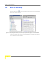
1.5 How to Get Help........................................................................................................... 14
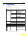
1.5.1 The Help Navigator ............................................................................................ 15
1.5.2 The Help Topic Window ..................................................................................... 17
Chapter 2 - Managing a Single Device/Cell
2.1 Introduction to Device Management ......................................................................... 22
2.2 The Device Page.......................................................................................................... 24
2.2.1 The Device General Tab .................................................................................... 24
2.2.2 The Device Versions Tab................................................................................... 29
2.3 Air Interface General Page ......................................................................................... 30
2.3.1 General Parameters........................................................................................... 33
2.3.2 Cell Distance Parameters (BreezeACCESS VL) ............................................... 34
Contents
2.3.3 Link Distance Parameters (BreezeNET B)......................................................... 36
2.3.4 ESSID Parameters............................................................................................. 37
2.3.5 Noise Immunity Parameters............................................................................... 38
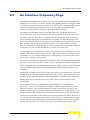
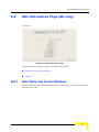
2.4 Air Interface Frequency Page..................................................................................... 41
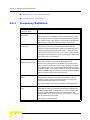
2.4.1 Frequency Definition .......................................................................................... 44
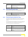
2.4.2 DFS Frequency Status Table............................................................................. 45
2.4.3 Planned Frequency Definition Table .................................................................. 45
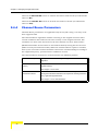
2.4.4 Channel Reuse Parameters............................................................................... 46
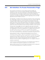
2.5 Air Interface Tx Power Parameters Page .................................................................. 47
2.5.1 Transmit Power Table ........................................................................................ 49
2.5.2 Maximum Transmit Power Table (SU & RB Only) ............................................. 50
2.5.3 General Tx Parameter........................................................................................ 50
2.5.4 ATPC Parameters .............................................................................................. 51
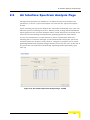
2.6 Air Interface Spectrum Analysis Page ...................................................................... 53
2.6.1 Spectrum Analysis Parameters.......................................................................... 54
2.6.2 Spectrum Analysis Table ................................................................................... 55
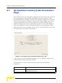
2.7 Air Interface Country Code Parameters Page .......................................................... 56
2.8 SUs Information Page (AU only) ................................................................................ 59
2.8.1 SUs Table and Control Buttons.......................................................................... 59
2.8.2 Details ................................................................................................................ 61
2.9 Gateways Page (AU Only) .......................................................................................... 62
2.10Wi2 APs (AU)/Wi2 AP (BU) ......................................................................................... 63
2.11Best AU Page (SU Only)/Best BU Page (RB Only)................................................... 65
2.11.1 Best AU/Best BU Parameters ............................................................................ 66
2.11.2 Neighboring AU/Neighboring BU Table ............................................................. 67
x
AlvariCRAFT User Manual
Contents
2.11.3 Selected AU/Selected BU Details ...................................................................... 69
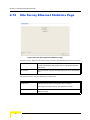
2.12Site Survey Ethernet Statistics Page ........................................................................ 70
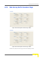
2.13Site Survey Rx/Tx Counters Page ............................................................................. 71
2.13.1 Rx Counters-Wireless Rx Counters ................................................................... 72
2.13.2 Rx Counters-Wireless Rx Events....................................................................... 72
2.13.3 Rx Counters-Concatenated Frames .................................................................. 73
2.13.4 Tx Counters-Frames To Wireless ...................................................................... 73
2.13.5 Tx Counters-Wireless Tx Events........................................................................ 74
2.13.6 Tx Counters-Concatenated Frames................................................................... 74
2.13.7 Tx Counters-Submitted Frames (Bridge) ........................................................... 74
2.13.8 Tx Counters-Retransmitted Frames................................................................... 75
2.13.9 Tx Counters-Dropped Frames ........................................................................... 75
2.13.10Tx Counters-Discarded CIR/MIR....................................................................... 75
2.13.11General Controls ............................................................................................... 75
2.14Site Survey Per SU Counters Page (AU) / Per RB Counters Page (BU)................. 77
2.15Site Survey Per Modulation Level Counters Page (SU & RB Only)........................ 79
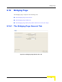
2.16Bridging Page ............................................................................................................. 81
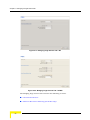
2.16.1 The Bridging Page General Tab ........................................................................ 81
2.16.2 The Bridging Page VLAN Tab............................................................................ 87
2.16.3 The Bridging Page Allow/Deny MAC Address List Tab (AU Only)..................... 91
2.17Service Parameters Page........................................................................................... 93
2.17.1 The Service Parameters Page General Tab ...................................................... 93
2.17.2 The Service Parameters Page Traffic Priority Tab........................................... 101
2.17.3 The Service Parameters Page DRAP Parameters Tab (AU Only) .................. 104
2.17.4 The Service Parameters Page WLP (Wireless Link Prioritization) Tab (AU &
AlvariCRAFT User Manual
xi
Contents
BU-B100 Only)106
2.18MAC Pin-Point Page (AU & BU Only) ...................................................................... 110
2.19Security Parameters Page ....................................................................................... 111
2.20Performance Parameters Page................................................................................ 115
2.20.1 Contention Window Parameters ...................................................................... 116
2.20.2 RTS Threshold (bytes) (AU & SU Only)........................................................... 117
2.20.3 Number of Hardware Retries ........................................................................... 117
2.20.4 AVG SNR Memory Factor................................................................................ 118
2.20.5 Maximum Modulation Level ............................................................................. 118
2.20.6 Multicast Modulation Level (AU & BU Only)..................................................... 119
2.20.7 Burst Mode Parameters ................................................................................... 119
2.20.8 Concatenation Parameters .............................................................................. 120
2.20.9 AIFS (AU & SU Only) ....................................................................................... 122
2.20.10Adaptive Modulation Parameters .................................................................... 123
2.20.11Recommended Maximum Modulation Levels ................................................. 124
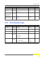
2.21IP Parameters Page .................................................................................................. 125
2.21.1 IP settings ........................................................................................................ 125
2.21.2 Run-Time IP Parameters ................................................................................. 125
2.21.3 DHCP Settings ................................................................................................. 126
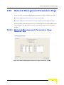
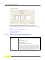
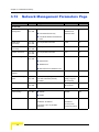
2.22Network Management Parameters Page ................................................................ 127
2.22.1 Network Management Parameters Page General Tab .................................... 127
2.22.2 Network Management Parameters Page Send Traps Tab (AU & BU Only) .... 131
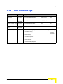
2.23Unit Control Page ..................................................................................................... 132
2.23.1 General ............................................................................................................ 133
2.23.2 Software Control .............................................................................................. 133
2.23.3 Configuration Control ....................................................................................... 135
xii
AlvariCRAFT User Manual
Contents
2.23.4 Parameters Not Changed After Set Complete Factory/Operator Default Configuration 136
2.23.5 Parameters Not Changed After Set Partial Factory/Operator Default Configuration
136
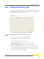
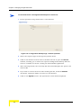
2.24Configuration Backup Page..................................................................................... 139
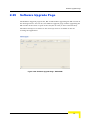
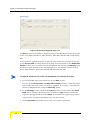
2.25Software Upgrade Page ........................................................................................... 141
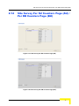
2.26Multiple Configuration Page (AU Only)................................................................... 144
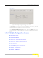
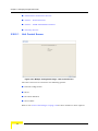
2.26.1 Using Multiple Configuration Screens .............................................................. 144
2.26.2 Multiple Configuration Screens ........................................................................ 145
2.26.3 Performing Multiple Configuration.................................................................... 158
2.27Performance Page .................................................................................................... 159
2.27.1 The Counters Selection Section....................................................................... 159
2.27.2 The Graph and Controls Section...................................................................... 161
AlvariCRAFT User Manual
xiii
Chapter 3 - Parameters Summary
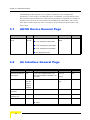
3.1 AU/SU Device General Page..................................................................................... 164
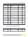
3.2 Air Interface General Page ....................................................................................... 164
3.3 Air Interface Frequency Page................................................................................... 165
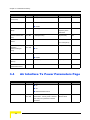
3.4 Air Interface Tx Power Parameters Page ................................................................ 166
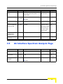
3.5 Air Interface Spectrum Analysis Page .................................................................... 167
3.6 Air Interface Country Code Parameters Page ........................................................ 168
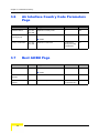
3.7 Best AU/BU Page....................................................................................................... 168
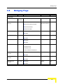
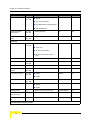
3.8 Bridging Page ............................................................................................................ 169
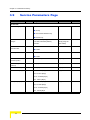
3.9 Service Parameters Page ......................................................................................... 172
3.10Security Parameters Page ....................................................................................... 175
3.11Performance Parameters Page................................................................................ 176
3.12IP Parameters Page .................................................................................................. 177
3.13Network Management Parameters Page ................................................................ 178
3.14Unit Control Page ..................................................................................................... 179
Figures
Figure 1-1: The Main Window ....................................................................................................... 4
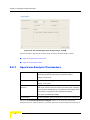
Figure 1-2: Equipment Type Selection .......................................................................................... 5
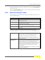
Figure 1-3: The Equipment Editor ................................................................................................. 6
Figure 1-4: The Device Manager Window................................................................................... 10
Figure 1-5: Help Navigator Window (Left) and Help Topic Window (Right)* in Undocked Mode 14
Figure 1-6: Contents Tab* ........................................................................................................... 16
Figure 1-7: Index Tab* ................................................................................................................ 17
Figure 2-1: The Device Page General Tab - AU ......................................................................... 24
Figure 2-2: The Device Page General Tab - SU ......................................................................... 25
Figure 2-3: The Device Page General Tab - BU ......................................................................... 25
Figure 2-4: The Device Page General Tab - RB ......................................................................... 26
Figure 2-5: The Device Page Versions Tab (AU)........................................................................ 29
Figure 2-6: Air Interface General Page - AU ............................................................................... 30
Figure 2-7: Air Interface General Page - SU ............................................................................... 30
Figure 2-8: Air Interface General Page - BU ............................................................................... 31
Figure 2-9: Air Interface General Page - RB ............................................................................... 31
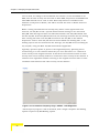
Figure 2-10: Air Interface Frequency Page - AU/BU* - DFS Supported...................................... 42
Figure 2-11: Air Interface Frequency Page - AU/BU - DFS Not Supported ................................ 43
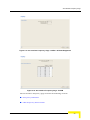
Figure 2-12: Air Interface Frequency Page - SU/RB ................................................................... 43
Figure 2-13: Air Interface Tx Power Parameters Page - AU/BU ................................................. 48
Figure 2-14: Air Interface Tx Power Parameters Page - SU/RB ................................................. 48
Figure 2-15: Air Interface Spectrum Analysis Page - AU/BU ...................................................... 53
Figure 2-16: Air Interface Spectrum Analysis Page - SU/RB ...................................................... 54
Figure 2-17: Air Interface Country Code Parameters Page - AU*............................................... 56
Figure 2-18: SUs Information Page............................................................................................. 59
Figure 2-19: Gateways Page ...................................................................................................... 62
Figures
Figure 2-20: Wi2 APs Page-AU................................................................................................... 63
Figure 2-21: Wi2 AP Page-BU .................................................................................................... 64
Figure 2-22: Best AU Page - SU ................................................................................................. 65
Figure 2-23: Best BU Page - RB ................................................................................................. 66
Figure 2-24: Site Survey Ethernet Statistics Page ...................................................................... 70
Figure 2-25: Site Survey Rx/Tx Counters Page - AU/BU ............................................................ 71
Figure 2-26: Site Survey Rx/Tx Counters Page - SU/RB ............................................................ 71
Figure 2-27: Site Survey Per SU Counters Page (AU)................................................................ 77
Figure 2-28: Site Survey Per RB Counters Page (BU)................................................................ 77
Figure 2-29: Site Survey Per Modulation Level Counters Page.................................................. 79
Figure 2-30: Bridging Page General Tab - AU ............................................................................ 81
Figure 2-31: Bridging Page General Tab - BU ............................................................................ 82
Figure 2-32: Bridging Page General Tab - SU/RB ...................................................................... 82
Figure 2-33: Bridging Page VLAN Tab - AU................................................................................ 87
Figure 2-34: Bridging Page VLAN Tab - SU................................................................................ 87
Figure 2-35: Bridging Page VLAN Tab - BU................................................................................ 88
Figure 2-36: Bridging Page VLAN Tab - RB................................................................................ 88
Figure 2-37: Bridging Page Allow/Deny MAC Address List Tab ................................................. 91
Figure 2-38: Service Parameters Page General Tab - AU.......................................................... 93
Figure 2-39: Service Parameters Page General Tab - SU.......................................................... 94
Figure 2-40: Service Parameters Page General Tab - RB.......................................................... 94
Figure 2-41: Service Parameters Page General Tab - BU.......................................................... 95
Figure 2-42: Service Parameters Page Traffic Priority Tab....................................................... 101
Figure 2-43: Service Parameters Page DRAP Tab................................................................... 105
Figure 2-44: Service Parameters Page WLP Tab ..................................................................... 107
Figure 2-45: MAC Pin-Point Page ............................................................................................. 110
Figure 2-46: Security Parameters Page - AU/BU...................................................................... 111
Figure 2-47: Security Parameters Page - SU/RB...................................................................... 112
Figure 2-48: Performance Parameters Page - AU/SU .............................................................. 115
Figure 2-49: Performance Parameters Page - BU/RB .............................................................. 115
xvi
AlvariCRAFT User Manual
Figures
Figure 2-50: IP Parameters Page.............................................................................................. 125
Figure 2-51: Network Management Parameters Page General Tab - AU/BU........................... 127
Figure 2-52: Network Management Parameters Page General Tab - SU/RB........................... 128
Figure 2-53: Network Management Parameters Page Send Traps Tab ................................... 131
Figure 2-54: Unit Control Page-AU/SU ..................................................................................... 132
Figure 2-55: Unit Control Page-BU/RU ..................................................................................... 132
Figure 2-56: Configuration Backup Page - Backup Operation .................................................. 139
Figure 2-57: Configuration Backup Page - Restore Operation.................................................. 140
Figure 2-58: Software Upgrade Page - SU/BU/RB ................................................................... 141
Figure 2-59: Software Upgrade Page - AU ............................................................................... 142
Figure 2-60: Multiple Configuration Page - Main Screen .......................................................... 145
Figure 2-61: Multiple Configuration Page - Unit Control Screen ............................................... 146
Figure 2-62: Multiple Configuration Page - IP Parameters Screen ........................................... 147
Figure 2-63: Multiple Configuration Page - Air Interface - General Parameters Screen ........... 148
Figure 2-64: Multiple Configuration Page - Air Interface - Frequency Parameters Screen ....... 149
Figure 2-65: Multiple Configuration Page - Best AU Screen ..................................................... 150
Figure 2-66: Multiple Configuration Page - Network Management - General Screen ............... 151
Figure 2-67: Multiple Configuration Page - Bridging - General Screen ..................................... 152
Figure 2-68: Multiple Configuration Page - Bridging - VLAN Screen ........................................ 153
Figure 2-69: Multiple Configuration Page - Performance Parameters Screen .......................... 154
Figure 2-70: Multiple Configuration Page - Service - General Screen ...................................... 155
Figure 2-71: Multiple Configuration Page - Service - Traffic Prioritization Screen .................... 156
Figure 2-72: Multiple Configuration Page - Security Screen ..................................................... 157
Figure 2-73: Performance Page ................................................................................................ 159
AlvariCRAFT User Manual
xvii
1
Chapter 1 - Using AlvariCRAFT
In This Chapter:
“Installing AlvariCRAFT” on page 2
“Getting Started” on page 4
“Using the Device Manager” on page 10
“How to Get Help” on page 14
Chapter 1 - Using AlvariCRAFT
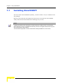
1.1
Installing AlvariCRAFT
The executable AlvariCRAFT file (Install_<version number>.exe) is available in the
CD package.
Run the executable file and follow the instructions to install the AlvariCRAFT
utility with the BreezeACCESS Device Manager on your PC.
NOTE
Installing AlvariCRAFT will automatically uninstall a previously installed version of AlvariCRAFT.
When a previous version is uninstalled automatically, the list of managable devices that is kept as a
part of AlvariCRAFT will be deleted.
The AlvariCRAFT application must be closed before starting installation of a new version.
2
AlvariCRAFT User Manual
Introduction
1.2
Introduction
AlvariCRAFT for BreezeACCESS family can be used to manage BreezeACCESS VL,
BreezeNET B, BreezeACCESS 4900 and BreezeACCESS EZ (AU-EZ) devices (it
does not support management of previous generation BreezeACCESS GFSK and
BreezeACCESS OFDM devices). The current release supports BreezeACCESS VL
and BreezeNET B equipment.
AlvariCRAFT enables on-line management of a selected single device, including
configuration, performance monitoring, software upgrade and configuration
backup/restore. It can also be used for managing an entire BreezeACCESS sector
(all or some of the SUs connected to one AU), including multiple configuration and
software upgrade.
AlvariCRAFT User Manual
3
Chapter 1 - Using AlvariCRAFT
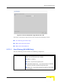
1.3
Getting Started
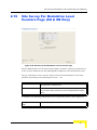
To open the AlvariCRAFT Device Manager:
Double-click on the AlvariCRAFT icon or open it from the windows Start menu
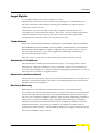
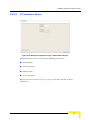
(Programs>AlvariCRAFT). The Main window opens, enabling view the current list
of the devices that can be managed by the AlvariCRAFT utility, add new devices to
the list, delete devices from the list and edit the relevant properties of the devices
in the list. You can open the Device Manager or establish a Telnet cut-through to
a selected device.
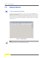
Figure 1-1: The Main Window
NOTE
When opened for the first time, the Managed Devices list is empty.
4
AlvariCRAFT User Manual
Getting Started
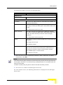
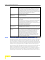
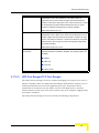
The following are the controls on the Main window:
Button
Description
New
Adds a new device to the list of devices that can be managed by the
utility. The list can include AUs and/or BUs. SUs/ RBs are typically
managed via the associated AU/BU. Refer to Open SU/RB below for
details on managing an SU/RB directly.
Configure
Opens the Device Manager (see “Managing a Single
Device/Cell” on page 21), allowing to manage the selected
device. Not available if two or more devices are selected, or if the
State is other than Up.
Edit
Opens the Equipment Editor (see below) for the selected device,
allowing to edit the device’s SNMP properties and its name in
AlvariCRAFT. The IP Address of a defined device cannot be editted.
Delete
Deletes the selected device(s) from the database. Select the
device(s) to remove and click Delete. The application prompts you for
confirmation. You can always redefine deleted devices.
Cut Through
Opens a Telnet session to the selected device. Not available if more
than one device is selected, or if the State is other than Up.
Export
Exports the list of selected devices with the relevant settings to a
Comma Separated Values (csv) file.
Import
Imports a Comma Separated Values (csv) file with managed devices
and their settings and adds them to the list of managed devices. An
existing device will be skipped.
Open SU/RB
Enables to define the required SNMP properties of a selected SU/RB
and open the Device Manager for the specified unit. The details of
this device will not be maintained in the managed devices list.
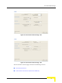
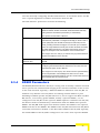
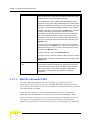
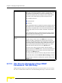
To add an AU or a BU to the Managed Devices list:
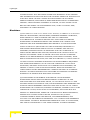
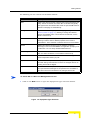
1
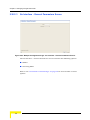
Click on the New button to open the Equipment Type selection window.
Figure 1-2: Equipment Type Selection
AlvariCRAFT User Manual
5
Chapter 1 - Using AlvariCRAFT
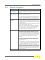
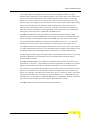
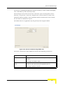
2
From the drop-down menu, select the Equipment Type: BreezeACCESS VL AU
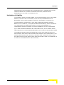
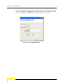
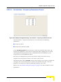
or BreezeNET B BU. Click OK. The Equipment Editor opens, allowing to define
the Device Name and SNMP properties of the device to be managed.
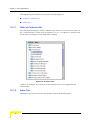
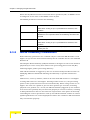
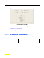
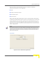
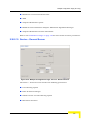
Figure 1-3: The Equipment Editor
6
AlvariCRAFT User Manual
Getting Started
The Equipment Editor includes the following fields:
Parameter
Description
NMS Reference
Device Name
The device’s name in the AlvariCRAFT utility.
SNMP Parameters
IP Address
The device’s IP Address. Read-only when editing the properties of a
previously defined device.
Read Community
The Read community string (password) for SNMP get operations.
This string is used by the SNMP agent to allow/disallow SNMP read
access.
The default Read Community is public.
Write Community
The Write community string (password) for SNMP set operations.
This string is used by the SNMP agent to allow/disallow SNMP write
access. The Write community can also be used for read (get)
operations.
The default Write Community is private.
Retries
The maximum number of retries for SNMP/TFTP communication with
the Device.
The range is from 0 to 255.
The default is 3 retries.
Timeout(s)
The maximum time in seconds that the requesting process waits for a
response from the Device before attempting a retransmission (or
aborting if the maximum number of retries has been reached).
The available range is 1 to 3600 seconds.
The default is 10 seconds.
3
Enter the Device Name (optional), IP Address, Read community and Write
community. Click OK.
NOTE
If the Read community string is entered in the Write Community text field, the user will get read-only
access rights to the device. For increased security, ESSID parameters are not available users with
read-only access rights.
The Write community string may also be entered in the Read Community text field.
4
The device’s is added to the Managed Devices list.
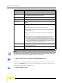
For each defined device, the following information is displayed in the Managed
Devices list:
AlvariCRAFT User Manual
7
Chapter 1 - Using AlvariCRAFT
Parameter
Description
Name
The name of the device as defined in the Equipment Editor (may differ
from the Device Name defined in the device).
Type and Model
The type and model of the device: AU-BS, RB-28, etc.
IP Address
The IP address of the device.
MAC Address
The MAC address of the device. Displayed only after connecting with the
device.
State
The connection state of the device:
Up if AlvariCRAFT can communicate with the device
Unreachable for a device that was reached in the past but cannot be
reached currently
Unknown for a device that was never reached by the AlvariCRAFT
utility.
Unmanageable for an SU/RB that is presented by the AU/BU as up
and running but cannot be managed by AlvariCRAFT. This can
happen if the devices uses a SW version below 5.0 or if it’s IP address
is on a subnet that cannot be reached by AlvariCRAFT or if either its
VLAN or Network Management parameters are configured so that it
cannot be managed by the AlvariCRAFT station.
Running SW Version
The running software version of the device. Displayed only after
connecting with the device.
HW Revision
The HW Revision of the device. Displayed only after connecting with the
device.
NOTE
Configuring wrong communities during the initial definition of the device in the Equipment Editor will
cause the device’s State to be presented as Unknown or Unreacheable.
To manage a device that is included in the Managed Devices list:
Double-click on the selected entry in the Managed Devices list, or select it and
click on the Configure button. The Device Manager for the selected entity opens,
displaying the main page for the device.
To manage an SU or an RB:
8
AlvariCRAFT User Manual
Getting Started
1
Click on the Open SU/RB button. The Equipment Editor for SU/RB opens,
allowing to define the Device Name and SNMP properties of the device to be
managed.
2
Enter the Device Name (optional) and SNMP properties of the device you want
to manage.
3
Click OK. The Device Manager for the specified device will open.
AlvariCRAFT User Manual
9
Chapter 1 - Using AlvariCRAFT
1.4
Using the Device Manager
This section includes:
“The Device Manager Components
“Common Control Buttons
“Hiding and Displaying the Navigation Pane
“Working with Tables
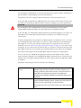
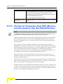
1.4.1
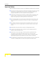
The Device Manager Components
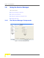
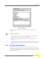
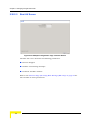
Figure 1-4: The Device Manager Window
10
AlvariCRAFT User Manual
Using the Device Manager
The Device Manager window comprises the following components:
1.4.2
Component
Description
Title Bar
Identifies the managed device's name (if defined) and IP address. It
also includes standard icons for minimizing, maximizing or closing the
Device Manager.
Navigation Pane
Displays all configuration/information pages and enables opening a
selected page by clicking on it.
Page Name
The name of the displayed page.
Selected Page
The selected page. Enables viewing/managing the applicable
parameters.
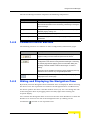
Common Control Buttons
The following buttons are common to most configuration/information pages.
Button
Description
Click on the Refresh button to update the information displayed in the
page according to current values acquired from the device.
Click on the Apply button to implement the modifications to the
configuration of the device. Exiting the Device Manager or switching
to another page without applying opens a confirmation dialog box,
enabling to decide whether to discard the changes or continue
editing.
This button is not available in information pages that display read-only
details and do not include any configurable parameters.
Help
1.4.3
Click on the Help button to open the Help Navigator, displaying the
Help topic for the current page.
Hiding and Displaying the Navigation Pane
By default, both the Navigation Pane and Work Area are displayed. When hovering
the mouse over the separation bar between the Navigation Pane and Work Area,
the mouse pointer becomes a double-headed arrow (↔). You can change the size
of the Navigation Pane by dragging this arrow left/right until reaching the
required display.
You can hide the Navigation Pane to increase the size of the Work Area or hide the
Work area to increase the size of the Navigation Pane by clicking on the
arrowheads (
AlvariCRAFT User Manual
) located on the separation bar.
11
Chapter 1 - Using AlvariCRAFT
With the Navigation Pane hidden or maximized, if clicking the arrowhead does not
restore the display of both panes, manually drag the separation bar to restore the
display.
1.4.4
Selecting Configurable Parameter’s Values
The following methods for selecting the required value for parameters within the
application are common to most configuration windows:
Dropdown Menus:
Parameters with several value options are configured
using dropdown menus that include the available
options. To configure these parameters, click on the
Dropdown box and select the required option from the
dropdown menu. The value is displayed in the field.
Up/Down
Parameters with value ranges are configured using up
Selection Arrows:
and down arrows to navigate through the range of values
available. Click the up and down arrows until the
required option is displayed in the field. You can also
enter the required value directly into the field.
Text Field:
Parameters that are defined using a string of characters
are configured using a text field. To change the setting,
mark the current settings and enter the new string. Note
that most parameters require a certain format (such as
IP address, MAC address, printable characters, etc)
1.4.5
Grayed-out Fields
Grayed-out fields are read-only. This may be due to the particular parameter
being read-only, or because another parameter must be changed to enable
read-write access for the required parameter.
1.4.6
Parameters that Require Reset
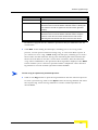
Certain parameters are applied in runtime, meaning that a change becomes
effective immediately after applying it (pressing the Apply button). Changes in
other parameters require resetting the device: the change is stored in the device,
but the new settings will take effect only after the device is reset. These
parameters are marked with an *, indicating that after completing all
configuration changes the device should be reset for the new settings to take
effect.
12
AlvariCRAFT User Manual
Using the Device Manager
1.4.7
Working with Tables
All AlvariCRAFT tables and lists allow sorting, resizing and rearranging the
column display sequence.
To sort a table:
Tables can be sorted in an ascending order by clicking on any of the column
headings. Click again on the column heading to sort in a descending order. Click
a third time to return to no sorting (default mode). When any column is used for
sorting in either ascending or descending order, the sorting order is indicated by a
small triangle next to the column’s heading.
To resize columns:
To resize a column, position the cursor on the border line between two columns
headings. The cursor changes into a double-headed arrow. Drag the cursor to the
left or to the right to increase or decrease the size of a column. All other columns
are resized automatically. The overall width of the table, however, does not
change.
To rearrange columns:
To rearrange the columns sequence, click a column header and drag it to the new
desired position.
AlvariCRAFT User Manual
13
Chapter 1 - Using AlvariCRAFT
1.5
How to Get Help
Click the Help button
to open the Help Navigator window and the Help Topic
window for a specific window.
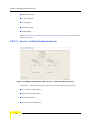
Figure 1-5: Help Navigator Window (Left) and Help Topic Window (Right)* in Undocked Mode
* This is an example: the contents of the Help Navigator and Help Topic Window
are not applicable for AlvariCRAFT.
14
AlvariCRAFT User Manual
How to Get Help
1.5.1
The Help Navigator
The Help Navigator window enables to view help contents, select a specific subject
or search for information.
The Help Navigator window includes the following items:
Menus
Menu
Sub-Menu*
Description
File
Display
<Ctrl-D>
Opens the selected topic in the Help Topic
window. Selecting the topic and then
selecting this menu is equivalent to
double-clicking on the topic.
Display in New Window
<Ctrl-W>
Displays the selected topic in a new window,
without closing a previously displayed topic.
Print Tree
<Ctrl-R>
Enables to print the topics tree as displayed
on the Help Navigator. You can expand or
collapse the tree nodes to change the
display before printing.
Print Topics
<Ctrl-S>
Enables to print the selected topic that is
displayed on the Help Topic window.
Close
<Ctrl-O>
Closes the Help Navigator window.
Exit
<Ctrl-X>
Closes all help windows and exits the Help
Navigator.
Table of Contents
Displays the Table of Contents tab.
Index
Displays the Index tab.
About
Opens the About window, displaying the
version details for the Help.
Tooltip
Description
Display
Opens the selected topic in the Help Topic
window. Selecting the topic and then
selecting this menu is equivalent to
double-clicking on the topic.
Display in New Window
Displays the selected topic in a new window,
without closing a previously displayed topic.
View
Help
Toolbar
Icon
* The keyboard shortcut is provided in angular brackets.
AlvariCRAFT User Manual
15
Chapter 1 - Using AlvariCRAFT
The Help Navigator window also includes the following tabs:
“Table of Contents Tab
“Index Tab
1.5.1.1
Table of Contents Tab
The Contents tab displays all the available topic nodes in tree structure. Click on
the + symbol next to a topic node to expand it, or on -, to collapse it. Double-click
on the topic to display it in the Help Topic window.
Figure 1-6: Contents Tab*
* This is an example: the contents of the Contents tab are not applicable for
AlvariCRAFT.
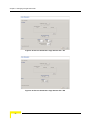
1.5.1.2
Index Tab
The Index tab enables to search for specific content in all help topics.
16
AlvariCRAFT User Manual
How to Get Help
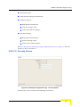
Figure 1-7: Index Tab*
* This is an example: the contents of the Index tab are not applicable for
AlvariCRAFT.
To search for information:
1
In the Index tab, type the keywords or the beginning of the keyword in the
designated field. A list of matching topics is displayed.
2
Select the topic that matches your query. The list of available topics is
displayed.
3
Select an item from the list and click Open to display the selected topic in the
Help Topic window. You can also double-click on the list item to display its
content.
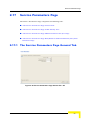
1.5.2
The Help Topic Window
The Help Topic window displays the content of the selected help topic. At the
bottom of each displayed topic are a back arrow and/or a forward arrow, enabling
to navigate between displayed topics. In addition, the Help Topic window includes
the following components:
AlvariCRAFT User Manual
17
Chapter 1 - Using AlvariCRAFT
Menus
Menu
Sub-Menu*
Description
File
Print Topic
<Ctrl+P>
Enables to print the selected topic on the active Help Topic
window.
Close
<Ctrl+O>
Closes the Help Topic window.
Exit
<Ctrl+X>
Closes all help windows and exits the Help Navigator.
Back
<Alt-Left>
Displays the previous topic. When the first topic is displayed,
this menu item is greyed out (unavailable for selection). Click
Alt and the left arrow on your keyboard to display previous
topics.
Forward
<Alt-Right>
Displays the next topic. When the last topic is displayed, this
menu item is greyed out (unavailable for selection). Click Alt
and the right arrow on your keyboard to display the next
topics.
Navigator
Activates/opens the navigator window.
Find
<Ctrl-F>
Enables to search for text on the active topic.
Dock/Undock
<Ctrl-K>/<Ctrl-U>
Merges/separates the Help Navigator and Help Topic
windows. When docked, a single menu bar displays all
available menus (File, View, Go, Tools, Help).
Tooltip
Description
Navigator
Activates/opens the navigator window.
Back
Displays the previous topic. When the first topic is displayed,
this menu item is greyed out (unavailable for selection). Click
Alt and the left arrow on your keyboard to display previous
topics.
Forward
Displays the next topic. When the last topic is displayed, this
menu item is greyed out (unavailable for selection). Click Alt
and the right arrow on your keyboard to display the next
topics.
Print Topic
Enables to print the selected topic on the active Help Topic
window.
Go
Tools
Toolbar
Icon
18
AlvariCRAFT User Manual
How to Get Help
AlvariCRAFT User Manual
Dock
Merges the Help Navigator and Help Topic windows. When
docked, a single menu bar displays all available menus (File,
View, Go, Tools, Help).
Undock
Separates the docked Help Navigator and Help Topic
windows.
19
2
Chapter 2 - Managing a Single Device/Cell
Chapter 2 - Managing a Single Device/Cell
2.1
Introduction to Device Management
The tree menu on the right side of the Device Manager window enables selecting
the following view and configuration pages:
“The Device Page” on page 24
Air Interface:
“Air Interface General Page” on page 30
“Air Interface Frequency Page” on page 41
“Air Interface Tx Power Parameters Page” on page 47
“Air Interface Spectrum Analysis Page” on page 53
“Air Interface Country Code Parameters Page” on page 56
“SUs Information Page (AU only)” on page 59
“Gateways Page (AU Only)” on page 62
“Wi2 APs (AU)/Wi2 AP (BU)” on page 63
“Best AU Page (SU Only)/Best BU Page (RB Only)” on page 65
Site Survey:
“Site Survey Ethernet Statistics Page” on page 70
“Site Survey Rx/Tx Counters Page” on page 71
“Site Survey Per SU Counters Page (AU) / Per RB Counters Page (BU)” on
page 77
“Site Survey Per Modulation Level Counters Page (SU & RB Only)” on
page 79
“Bridging Page” on page 81
“Service Parameters Page” on page 93
“MAC Pin-Point Page (AU & BU Only)” on page 110
22
AlvariCRAFT User Manual
Introduction to Device Management
“Security Parameters Page” on page 111
“Performance Parameters Page” on page 115
“IP Parameters Page” on page 125
“Network Management Parameters Page” on page 127
“Unit Control Page” on page 132
“Configuration Backup Page” on page 139
“Software Upgrade Page” on page 141
“Multiple Configuration Page (AU Only)” on page 144
“Performance Page” on page 159
AlvariCRAFT User Manual
23
Chapter 2 - Managing a Single Device/Cell
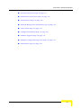
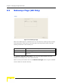
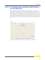
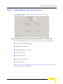
2.2
The Device Page
The Device page enables viewing general details of the selected device and its
hardware and software versions. It also enables configuring the Ethernet
Negotiation Mode of the device.
The Device page comprises two tabs:
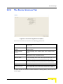
“The Device General Tab”
“The Device Versions Tab”
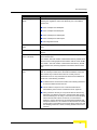
2.2.1
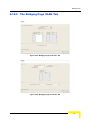
The Device General Tab
Figure 2-1: The Device Page General Tab - AU
24
AlvariCRAFT User Manual
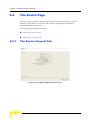
The Device Page
Figure 2-2: The Device Page General Tab - SU
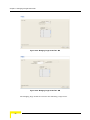
Figure 2-3: The Device Page General Tab - BU
AlvariCRAFT User Manual
25
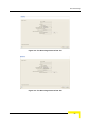
Chapter 2 - Managing a Single Device/Cell
Figure 2-4: The Device Page General Tab - RB
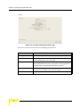
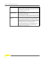
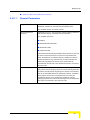
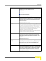
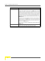
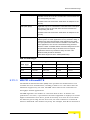
The Device General tab includes the following parameters:
26
Parameter
Description
Unit Type
A read-only display of the unit's function (AU-BS, BU-100, etc).
Unit Name
A read-only display of the Unit Name (if configured). The Unit Name
can be modified in the Unit Control page.
Serial Number
A read-only display of the unit’s Serial Number. Applicable only to
units supplied with SW version 4.5 and higher. In units upgraded from
a version below 4.5 this parameter will be none (empty).
Location
A read-only display of the unit’s Location (if configured). The device’s
Location can be modified in the Unit Control page.
MAC Address
A read-only display of the unit's unique IEEE MAC address.
AlvariCRAFT User Manual
The Device Page
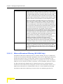
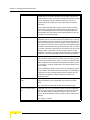
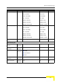
Parameter
Description
Ethernet Negotiation
Mode
The Ethernet Port Negotiation Mode dropdown menu enables
defining the negotiation mode of the Ethernet port. The available
options are:
Force 10 Mbps and Half-Duplex
Force 10 Mbps and Full-Duplex
Force 100 Mbps and Half-Duplex
Force 100 Mbps and Full-Duplex
Auto Negotiation Mode
Current Ethernet Port
State
A read-only display of the current speed and duplex of the Ethernet
port.
Time Since Last Reset
A read-only display of the elapsed time since the last reset of the
device.
Number Of Associations
Since Last Reset
A read-only display of the number of associations made by the device
since the last reset.
For SU/RB - The total number of associations with any AU/BU since
the last reset, including duplicate associations with the same AU/BU.
For AU/BU - The total number of associations with with any SU/RB
since the last reset, including duplicate associations with the same
unit.
Number Of Associated
SUs
Applicable only for AU. A read-only display of the total number of SUs
that are currently included in the Associations Database. Note that
this number may include units that are not currently active or
associated. An SU is only removed from the list of associated SUs
under one of the following conditions:
A SNAP frame is received from another AU indicating that the SU
is now associated with the other AU.
The SU failed to respond to 100 consecutive data frames
transmitted by the AU and is considered to have "aged out".
During the last 6 minutes (or more) the SU did not transmit any
data frame, and failed to respond to certain frames that typically
are transmitted by the AU every 10 seconds. Since the sampling
interval for this state is about 10 minutes, it means that the
decision to remove the SU from the Associations Database will
take place between 6 to 16 minutes from the time the SU ceased
sending data or responding to these "keep-alive" frames (for AUS
the sampling interval is 1 minute, meaning decision time of 6 to 7
minutes).
AlvariCRAFT User Manual
27
Chapter 2 - Managing a Single Device/Cell
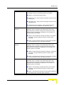
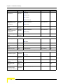
Parameter
Description
Associated AU
Applicable only to SU. A read-only display of the MAC address of the
AU with which the device is currently associated. If the device is not
associated with any AU, the address defaults to the IEEE broadcast
address, which is FF-FF-FF-FF-FF-FF (typically an SU that is not
associated to any AU will not be reachable).
Click on the Open button next to the display field to open a Device
Manager window for the associated AU.
Associated BU
Applicable only to RB. A read-only display of the MAC address of the
BU with which the device is currently associated. If the device is not
associated with any BU, the address defaults to the IEEE broadcast
address, which is FF-FF-FF-FF-FF-FF (typically an RB that is not
associated to any BU will not be reachable).
Click on the Open button next to the display field to open a Device
Manager window for the associated BU.
Associated RB
Applicable only to BU. A read-only display of the MAC address of the
RB with which the device is currently associated. If the device is not
associated with any RB, the address defaults to the IEEE broadcast
address, which is FF-FF-FF-FF-FF-FF.
Click on the Open button next to the display field to open a Device
Manager window for the associated RB.
WI2 AP Client
Applicable only to SU & RB. A read-only display of the IP address of a
WI2 Access Point connected to the SU/RB (0.0.0.0 means none). The
IP address of a connected WI2 AP can be configured in the Network
Management Parameters page.
Click on the Cut-Through button next to the display field to open an
HTTP session with the WI2 Access Point.
28
AlvariCRAFT User Manual
The Device Page
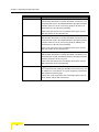
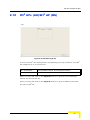
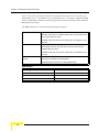
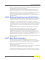
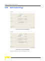
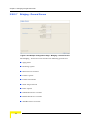
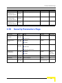
2.2.2
The Device Versions Tab
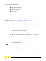
Figure 2-5: The Device Page Versions Tab (AU)
The Device Versions tab includes the following parameters:
Main Software Version
A read-only display of the software version currently defined as the
main version.
Shadow Software
Version
A read-only display of the software version currently defined as the
shadow version.
Running Software
Version
A read-only display of the software version of the currently running
version.
Running From
A read-only display indicating whether the unit is running from the
Main Version or from the Shadow Version.
Main File Name
A read-only display of the name of the compressed file (with a ".bz"
extension) of the version currently defined as the main version.
Shadow File Name
A read-only display of the name of the compressed file (with a ".bz"
extension) of the version currently defined as the shadow version.
Boot Version
A read-only display of the version of the BOOT firmware.
Hardware Revision
A read-only display of the revision of the unit hardware. Except to
SU-I all-indoor units, this is the hardware revision of the outdoor unit.
For more details on software versions and how to manage them, refer to the Unit
Control page.
AlvariCRAFT User Manual
29
Chapter 2 - Managing a Single Device/Cell
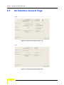
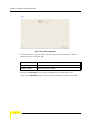
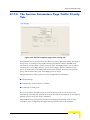
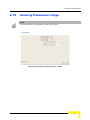
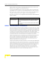
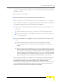
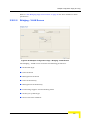
2.3
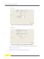
Air Interface General Page
Figure 2-6: Air Interface General Page - AU
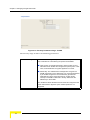
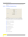
Figure 2-7: Air Interface General Page - SU
30
AlvariCRAFT User Manual
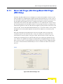
Air Interface General Page
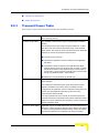
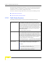
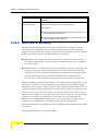
Figure 2-8: Air Interface General Page - BU
Figure 2-9: Air Interface General Page - RB
The Air Interface General page includes the following sections:
“General Parameters”
“Cell Distance Parameters (BreezeACCESS VL)”
AlvariCRAFT User Manual
31
Chapter 2 - Managing a Single Device/Cell
“Link Distance Parameters (BreezeNET B)”
“ESSID Parameters”
“Noise Immunity Parameters”
32
AlvariCRAFT User Manual
Air Interface General Page
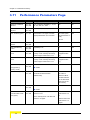
2.3.1
General Parameters
Radio Band (GHz)
A read-only display of the radio band of the unit.
Current Operating
Frequency (MHz)
A read-only display of the current operating frequency of the device.
For details on setting frequenies, refer to the Air Interface Frequency
page.
Maximum Number Of
Associations Limit
Applicable only for AU. A read-only display of the maximum number
of SUs that can associate with the AU.
For a regular AU, the Maximum Number Of Association Limit is 512
when data encrypyion is disabled and 124 when data encryption is
enabled. For AUS the Maximum Number Of Association Limit is 8.
Maximum Number Of
Associations
Applicable only for AU. The Maximum Number Of Associations
parameter defines the maximum number of SUs that can become
associated with the AU, while still guaranteeing the required quality of
service to customers.
Available values range from 0 to 512 for a regular AU (0 to 124 when
data encription is enabled), 0 to 8 for AUS.
Note that for a regular AU the Maximum Number Of Associations
must be set to a value of 124 or lower to enable data encryption. As
long as data encryption is enabled, the Maximum Number Of
Associations cannot be set to a value higher than 124.
Antenna Gain (dB)
The Antenna Gain parameter enables to define the net gain of a
detached antenna. The configured gain should take into account the
attenuation of the cable connecting the antenna to the unit. The
Antenna Gain is important especially in countries where there is a
limit on the EIRP allowed for the unit; where the maximum allowed
value for the Transmit Power parameters cannot exceed the value of
(EIRP - Antenna Gain). The EIRP is defined in the selected
Sub-Band.
In certain units with an integral antenna the Antenna Gain is not
configurable, and it is available as a read-only display of the net gain
of the inegral antenna.
The range (in dBi) is from 0 to either 50 or Regulation Maximum EIRP
+ 10 (the lowest of the two values). If Regulation Maximum RIRP is
No Limit, than the highest limit is 50). A value of "Don't Care"
(presented as -2) means that the actual value is not important since
there is no limitation on the EIRP in the Country Code being used by
the unit. A value of "Not Set Yet" (presented as -1) means that the unit
will not transmit until the actual value is configured. Once a value is
configured, it is not possible to reconfigure the unit to either "Don't
Care" or "Not Set Yet".
AlvariCRAFT User Manual
33
Chapter 2 - Managing a Single Device/Cell
Lost Beacon Watchdog
Threshold
Applicable only for AU & BU. When it is unable to send beacon
frames for a predetermined period of time, such as in the case of
interferences, the AU/BU resets itself. The Lost Beacon Watchdog
Threshold parameter defines the number of consecutive lost beacons
after which the unit will reset itself.
The configurable range for this parameter is 100 - 1000. When the
checkbox is unchecked, the parameter is set to 0, disabling the
feature (internal refresh will never be performed). To activate the
feature, check the checkbox.
Wireless Trap Threshold
(%)
Applicable only for AU & BU. The Wireless Link Trap Threshold
parameter defines the threshold for the wireless quality trap,
indicating that the quality of the wireless link has dropped below (On
trap) or has increased above (Off trap) the specified threshold.
The Wireless Link Trap Threshold is in percentage of
retransmissions, and the range is from 1 to 100 (%).
Scanning Mode
Applicable only for SU & RB. The Scanning Mode parameter defines
whether the device will use Passive or Active scanning when
searching for an AU/BU.
In passive scanning, the device "listens" to the wireless medium for
approximately two seconds at each frequency, searching for
beacons. The disassociation period, which is the time from the
moment the link was lost until the device decides that it should start
searching for another AU/BU, is approximately seven seconds.
In some situations when there is a high probability that SU/RB may
need to roam among different AUs/BUs, the use of active scanning
enables to significantly reduce the link establishment time. This is
achieved by using shorter dwell periods, transmitting a Probe
Request at each frequency. This reduces the time spent at each
frequency as well as the disassociation period.
When DFS is supported by the Country Code being used by the unit,
Scanning Mode is forced to Passive.
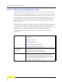
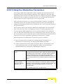
2.3.2
Cell Distance Parameters (BreezeACCESS VL)
The higher the distance of an SU from the AU that is serving it, the higher the time
it takes for messages sent by one of them to reach the other. To ensure
appropriate services to all SUs regardless of their distance from the AU, while
maintaining a high overall performance level, two parameters are adapted to the
distances of SUs from the serving AU:
1
The time that a unit waits for a response message before retransmission (ACK
timeout) should take into account the round trip propagation delay between
the AU and the SU (The one-way propagation delay at 5 GHz is 3.3
34
AlvariCRAFT User Manual
Air Interface General Page
microseconds per km/5 microseconds per mile.). The higher the distance from
the AU of the SU served by it, the higher the ACK timeout should be.
The ACK timeout in microseconds is: 20+Distance (km)*2*3.3 or 20+Distance
(miles)*2*5.
2
To ensure fairness in the contention back-off algorithm between SUs located at
different distances from the AU, the size of the time slot should also take into
account the one-way propagation delay. The size of the time slot of all units in
the cell should be proportional to the distance from the AU of the farthest SU
served by it.
The Cell Distance Option in an AU defines the method of computing distances.
When set to Manual, the Max Cell Distance parameter should be configured with
the estimated distance of the farthest SU served by the AU. When set to
Automatic, the AU uses a special algorithm to estimate its distance from each of
the SUs it serves, determine which SU is located the farthest and use the
estimated distance of the farthest SU as the maximum cell/link distance. The
value of the maximum cell distance parameter (either computed or configured
manually) is transmitted in the beacon messages to all SUs served by the AU, and
is used by all units to calculate the size of the time slot, that must be the same for
all units in the same sector. When the Per SU Distance Learning option is
enabled, the AU uses the re-association message to send to each SU its estimated
distance from the AU. The per-SU distance is used to calculate the ACK timeout to
be used by the SU. When the Per SU Distance Learning option is disabled (or if it
cannot be used because the SU uses a SW version that does not support this
feature), the SU will use the maximum cell distance to calculate the ACK timeout.
The AU always uses the maximum cell distance to calculate the ACK timeout.
It should be noted that if the size of the time slot used by all units is adapted to
the distance of the farthest unit, then no unit will have an advantage when
competing for services. However, this reduces the overall achievable throughput of
the cell. In certain situations, the operator may decide to improve the overall
throughput by reducing the slot size below the value required for full fairness.
This means that when there is competition for bandwidth, the back-off algorithm
will give an advantage to SUs that are located closer to the AU
The Cell Distance parameters includes the following:
Cell Distance Option
Applicable only for AU. The Cell Distance Option defines whether the
maximum distance of the AU from any of the SUs it serves will be
determined manually (using the Maximum Cell Distance parameter)
or automatically.
The Options are Automatic or Manual.
AlvariCRAFT User Manual
35
Chapter 2 - Managing a Single Device/Cell
Fairness Factor (%)
Applicable only for AU. The Fairness Factor enables to define the
level of fairness in providing services to different SUs. When set to
100%, all SUs have the same probability of getting services when
competing for bandwidth. If set to X%, then SUs located up to X% of
the maximum distance from the AU will have an advantage in getting
services over SUs located farther than this distance.
The range is from 0 to 100 (%).
Measured Max Cell
Distance (Km)
A read-only display of the measured distance from the AU of the
farthest unit served by it.
Max Cell Distance (Km)
Applicable only for AU. The Maximum Cell Distance parameter allows
configuring the maximum distance when the Cell Distance Option is
set to Manual.
The range is from 0 to 54 (Km). The value of 0 has a special meaning
of No Compensation: Acknowledge Time Out is set to a value
representing the maximum distance of 54 km. The time slot size is set
to its minimal value of 9 microseconds.
The default is 0 (No Compensation).
Most Distant Unit
Applicable only for AU. A read-only display of the MAC Address of the
most distant unit served by the AU
Per SU Distance
Learning
Applicable only for AU. Available only when the Cell Distance Mode is
set to Automatic. The Per SU Distance Learning option defines the
mode in which SUs calculate the ACK timeout: based on the
maximum cell distance or on the actual distance from the AU.
When this feature is disabled, all SUs in the cell use for the
calculation of the ACK timeout the maximum cell distance; when
enabled, each SU uses instead its actual distance from the AU.
The options are Disable or Enable.
2.3.3
Link Distance Parameters (BreezeNET B)
The higher the distance between the RB and the BU that is serving it, the higher
the time it takes for messages sent by one of them to reach the other. The time
that a unit waits for a response message before retransmission (acknowledge time
delay) should take into account the round trip propagation delay between the two
units (the one-way propagation delay at 5 GHz is 3.3 microseconds per km/5
microseconds per mile). The higher the distance between the BU and the RB, the
higher the acknowledge time delay used by both units should be. The ACK
timeout in microseconds is: 20+Distance (km)*2*3.3 or 20+Distance (miles)*2*5.
The distance between the BU and the RB can be determined either manually or
automatically. In manual mode, the estimated distance between the two units is
36
AlvariCRAFT User Manual
Air Interface General Page
used for manually configuring the Max Link distance. In automatic mode, the BU
uses a special algorithm to estimate its distance from the RB.
The Link Distance parameters includes the following:
Link Distance Option
Applicable only for BU. The Link Distance Option defines whether the
distance between the BU and the RB will be determined manually
(using the Max Link Distance parameter) or automatically.
The Options are Automatic or Manual.
Fairness Factor (%)
Applicable only for BU. The Fairness Factor defines the effect of the
Link Distance (calculated or configured manually) on the slot size. In
good quality links, the minimal slot size (9 microseconds) can be
used, providing maximum throughput. In a link with poor conditions
(such as a high interference level), the slot size should be increased
to enable better performance. The higher the Fairness Factor, the
higher is the impact of the Link Distance on the actual slot size.
The range is from 0 to 100 (%). A value of 100 (%) means maximum
impact of the distance on the slot size.
Measured Max Link
Distance (Km)
A read-only display of the measured distance between the BU and
the RB.
Max Link Distance (Km)
Applicable only for BU. The Max Link Distance parameter allows
configuring the estimated distance between the two units when the
Link Distance Option is set to Manual.
The range is from 0 to 54 (Km). The value of 0 has a special meaning
of No Compensation: Acknowledge Time Out is set to a value
representing the maximum distance of 54 km. The time slot size is set
to its minimal value of 9 microseconds.
2.3.4
ESSID Parameters
The ESSID (Extended Service Set ID) is a string used to identify a wireless network
and to prevent the unintentional merging of two wireless networks or two sectors
in the same network. Typically, a different ESSID is defined for each AU/BU. To
facilitate easy addition of an SU/RB to an existing network without a prior
knowledge of which specific AU/BU will serve it, and to support the Best AU/Best
BU feature, a secondary "global" ESSID, namely "Operator ESSID", can be
configured in the AU/BU. If the Operator ESSID Option is enabled at the AU/BU,
the Beacon frames transmitted by it will include both the ESSID and Operator
ESSID. The SU/RB shall regard such frames if either the ESSID or the Operator
ESSID matches it own ESSID. The ESSID of the AU/BU with which the SU/RB is
eventually associated is defined as the Run-Time ESSID of the SU/RB. Typically,
the initial ESSID of the SU/RB is configured to the value of the Operator ESSID.
AlvariCRAFT User Manual
37
Chapter 2 - Managing a Single Device/Cell
When the SU/RB has become associated with a specific AU/BU, its ESSID can be
reconfigured to the value of the ESSID of the AU/BU.
The ESSID parameters includes the following:
ESSID
The ESSID of the unit.
Valid values: A string of up to 31 printable ASCII characters, case
sensitive.
Operator ESSID Option
Applicable only for AU & BU. The Operator ESSID Option enables or
disables the use of Operator ESSID for establishing association with
SUs/RB.
Operator ESSID
Applicable only for AU & BU. The Operator ESSID.
Valid values: A string of up to 31 printable ASCII characters, case
sensitive.
Runtime ESSID
2.3.5
Applicable only for SU & RB. Read-only display of the actual ESSID
used by the unit.
Noise Immunity Parameters
Noise Immunity parameters are available only for units with HW Revision C and
higher, except to Pulse Detection Sensitivity that is available also for unit with HW
Revision B.
The Adaptive Noise Immunity (ANI) mechanism is designed to reduce the wireless
physical layer errors and by that enhance the processing power of the AU/BU,
delivering higher packet processing efficiency.
This ANI mechanism is triggered by the rate of detected Physical Errors and it is
modifying different thresholds affecting the immunity to specific interference
types.
This feature, active by default, exists in all units with HW revision C and higher
running SW version 3.0 and higher. Starting in SW version 4.0, the processing
power of the system has been increased dramatically. When using version 4.0 or
higher, the units are capable to process more packets per seconds, including
physical error packets. As a result, the ANI mechanism (triggered by the number
of received error packets) may not function properly in certain scenarios, resulting
in link performances that are far below the expectations. The option of manually
controlling the various parameters used by the ANI mechanism enables to achieve
optimal performance in certain deployments where the automatic ANI mechanism
may not function properly.
38
AlvariCRAFT User Manual
Air Interface General Page
It is strongly recommended to consult with Alvarion's experts before switching to
manual mode and modifying any of the parameters.
The general rules for using the Noise Immunity Control parameters are:
In the SU/RB, if performance (Modulation Level) is lower than expected based on
the SNR, try switching to Manual mode without changing any of the parameters.
CAUTION
Do not change any of the SU's/RB’s Noise Immunity Control parameters (except the Noise
Immunity State Control) from remote, as it may result in loss of connectivity to the unit.
In the AU/BU, try switching to Manual mode if overall throughput is too low or if
SUs/RB are lost although communication conditions are sufficient for good
connectivity.
In many deployments the transition to Manual mode is sufficient. If not, you may
try changing the Noise Immunity Level and/or Spur Immunity Level parameters.
The target is to reduce the amount of Phy Error rate reported by the unit (see
Total Rx events in “Site Survey Rx/Tx Counters Page” on page 71). To ensure that
sensitivity is not reduced too much and SUs are not lost, verify that the Age of all
SUs/RB is below 20 seconds (The age of all SUs/RB can be viewed in the Display
Association Info option of the AU/BU MAC Address Database using Telnet).
Do not activate the OFDM Weak Signal parameter if the SNR is below 36 dB.
Under normal conditions, the OFDM Weak Signal should never be activated in the
AU/BU, since the SNR of all SUs/RB served by it will be below 36 dB when ATPC
is enabled.
The Noise Immunity parameters includes the following:
Noise Immunity State
Control
The Noise Immunity State Control defines the activation mode of the
Adaptive Noise Immunity mechanism: Automatic or Manual. The
following parameters of the Noise Immunity Control mechanism are
applicable only for Manual mode (except to Pulse Detection
Sensitivity that is applicable regardliss of the selected option for this
parameter).
Noise Immunity Level
The Noise Immunity Level parameter sets the threshold for immunity
against broadband interfering signals. A higher value may reduce the
number of errors at the expense of reduced sensitivity.
The range is from 0 to 4. In the current version only 0 and 4 should be
used.
AlvariCRAFT User Manual
39
Chapter 2 - Managing a Single Device/Cell
Spur Immunity Level
The Spur Immunity Level parameter sets the threshold for immunity
against narrow band interfering signals such as spurious from signals
at other frequencies. A higher value may reduce the number of errors
at the expense of reduced sensitivity.
The range is from 0 to 7.
OFDM Weak Signal
The OFDM Week Signal parameter sets the threshold for immunity
against interfering OFDM signals.
The available options are Disable and Enable. Enable means that the
unit will immediately reject OFDM packets with a relatively low SNR.
Pulse Detection
Sensitivity
The Pulse Detection Sensitivity parameter affects the Phy error count:
If it is set to Low, than all Phy errors will be reported as regular Phy
errors, regardless of the signal level. If it is set to High, all Phy errors
with levels bellow a certain threshold (not accessible to the user) will
be reported as regular Phy errors, while those with levels higher than
the threshold will be reported as detected radar pulses.
When DFS (radar detection) is used, or during Spectrum analysis
test, the Pulse Detection Sensitivity is set internally to High
(regardless of the configured option).
40
AlvariCRAFT User Manual
Air Interface Frequency Page
2.4
Air Interface Frequency Page
To simplify installation and changes, most of the parameters that determine the
frequency to be used are set in the AU/BU. The SU/RB should be configured with
a minimal set of parameters to ensure that it will be able to automatically detect
and use the frequency/bandwidth used by the AU/BU, including possible
changes in this frequency (Automatic Sub Band Select feature).
To simplify the installation process the SU/RB scans a definable frequencies
subset after power-up. The defined frequencies subsets may include frequencies
from more than one Sub-Band, enabling automatic detection of both frequency
and bandwidth. If the Best AU/BU feature is enabled, the SU/RB will scan the
defined subset and the operating frequency/bandwidth will be determined by the
Best AU/BU mechanism (including the optional use of the Preferred AU/BU
feature). Otherwise the SU/RB will try to associate with the first AU/BU it finds. If
no AU/BU is found, the SU/RB will start another scanning cycle.
In some regions, it is important to ensure that wireless access equipment does not
interfere with certain radar systems in the 5 GHz band. If radar is being detected,
the wireless access network should move automatically to a frequency that does
not interfere with the radar system.
The country dependent set of parameters includes also an indication whether DFS
(Dynamic Frequency Selection) should be used. The DFS algorithm is designed to
detect and avoid operation in channels with radar activity. If the current sub-band
does not support DFS, then the DFS parameters configuration submenu is not
available.
When DFS is enabled, the AU/BU monitors the spectrum continuously, searching
for signals with a specific pattern indication radar activity. Upon detecting radar
activity, the AU/BU immediately stops transmitting on this frequency and starts
looking for another radar-free frequency. The subset of viable frequencies is
configurable.
The AU/BU maintains a continuously updated database of all applicable
frequencies, where each frequency is marked as Radar Free, Radar Detected or
Adjacent to Radar. The AU/BU attempts to check a new frequency only if it is
marked as Radar Free. If a radar activity was detected on a certain frequency, it
will be marked in the database as a Radar Detected frequency. The AU/BU will
not attempt to check for radar activity in frequencies marked as Radar Detected. A
certain time after detecting radar activity on a frequency, it will be removed from
the list of Radar Detected frequencies and will be marked as Radar Free. If radar
activity was detected on a certain frequency, adjacent channels should not be
AlvariCRAFT User Manual
41
Chapter 2 - Managing a Single Device/Cell
used as well, according to the bandwidth. For instance, if the bandwidth is 20
MHz, then if radar activity was detected in 5800 MHz, frequencies 5790 MHz and
5810 MHz should not be used as well. These frequencies are marked in the
database as Adjacent to Radar, and will be treated the same as Radar Detected
frequencies.
Before ceasing transmission on the frequency where radar signals had been
detected, the AU/BU sends a special disassociation message to its associated
SUs/RB. This message includes an indication whether the SUs/RB should wait
for this AU/BU. If the SUs/RB should wait, the message includes also the waiting
time. During this time each SU/RB searches for the AU/BU in the defined
frequencies subset. If the AU/BU was not found within the waiting time, or if a
waiting request was not included in the message, the SU/RB starts searching for
any AU/BU, using the Best AU/BU mechanism if applicable.
Typically, operators prefer to preserve the original frequency planning and to
avoid moving to a new channel unless they are sure that there is a continuous
radar activity in the original channel. It should be noted that detection of radar
activity does not necessarily indicate a continuous radar activity in the channel. A
channel reuse algorithm enables returning to the original channel under certain
conditions that indicates low radar activity on the channel.
Figure 2-10: Air Interface Frequency Page - AU/BU* - DFS Supported
* The Frequency Page for a BU is identical, with a single exception: SU Waiting
Option is replaced by RB Waiting Option.
42
AlvariCRAFT User Manual
Air Interface Frequency Page
Figure 2-11: Air Interface Frequency Page - AU/BU - DFS Not Supported
Figure 2-12: Air Interface Frequency Page - SU/RB
The Air Interface Frequency page includes the following sections:
“Frequency Definition”
“DFS Frequency Status Table”
AlvariCRAFT User Manual
43
Chapter 2 - Managing a Single Device/Cell
“Planned Frequency Definition Table”
“Channel Reuse Parameters”
2.4.1
Frequency Definition
Current Operating
Frequency (MHz)
A read-only display of the current operating frequency.
DFS Required By
Regulations
Applicable only for AU/BU that uses a Country Code supporting DFS.
Channel Avoidance
Period (min)
Applicable only for AU/BU that uses a Country Code supporting DFS.
When DFS is enable, this parameter defines the time that the
frequency will remain marked in the database as Radar Detected or
Adjacent to Radar after detecting radar activity. These frequencies
will not be used when searching for a new frequency. When this time
has elapsed, the unit frequency's marking will change to Radar Free.
The DFS Required by Regulations option enables defining whether
DFS should be used for compliance with applicable local regulations.
The options are Yes or No. Selection of the No option will disable the
radar detection and dynamic frequency selection mechanism.
The range is from 1 to 60 minutes.
SU Waiting Option (AU)
RB Waiting Option (BU)
Defined Frequency
(MHz)
Applicable only for AU/BU that uses a Country Code supporting DFS.
When DFS is enable, this parameter defines whether the
disassociation message sent by the AU/BU, after detecting radar
activity on the current frequency, will include a message instructing
the SU/RB to search only for the AU/BU before attempting to search
for another AU/BU. The message includes also the time period during
which the SU/RB should not search for any other AU/BU. The waiting
time is the Channel Check Time plus 5 seconds.
Applicable only for AU/BU. This parameter defines the
transmit/receive frequency when DFS is not enabled. If DFS is
enabled, it sets the initial operational frequency to be used upon
starting the DFS mechanism for the first time.
The range depends on the Country Code and selected Sub-Band.
Channel Check Time
(sec)
Applicable only for AU/BU that uses a Country Code supporting DFS.
When DFS is enable, this parameter defines the time allocated for
checking whether there is a radar activity on a new frequency after
power up or after attempting to move to a new frequency upon
detecting radar activity on the previously used frequency. During this
time the AU/BU does not transmit.
The range is 1 to 3600 seconds.
44
AlvariCRAFT User Manual
Air Interface Frequency Page
Minimum Pulses To
Detect
Applicable only for AU/BU that uses a Country Code supporting DFS.
When DFS is enable, this parameter defines the minimum number of
radar pulses that should be detected before reaching a decision that
radar is active on the channel.
The range is from 1 to 100 pulses.
Current Bandwidth
2.4.2
A read-only display of the current bandwidth used by the unit.
DFS Frequency Status Table
This read-only table is applicable only for AU/BU supporting DFS when DFS is
enabled. Each entry in the table includes the following parameters:
Frequency (MHz)
The tested frequency
Detection Status
The status of the frequency in the device’s database: Radar Free,
Radar Detected or Adjacent to Radar.
Check the Clear Detection Status After Reset check-box to set all Detection
Status entries to Radar Free after the next reset of the unit.
2.4.3
Planned Frequency Definition Table
For an AU/BU, this table is available only in unit using a Country Code that
supports DFS. It enables defining the frequencies that will be used in the DFS
mechanism when enabled. It includes all the frequencies of the selected
Sub-Band.
For an SU/RB, this table enables defining for each of the available Sub-Bands the
frequencies that will be used by the SU/RB when scanning for an AU/BU. For
each available Sub-Band, all the available frequencies are displayed.
Each entry in the table includes the following parameters:
Sub Band
Applicable only for SU & RB. The read-only number of the Sub Band.
Bandwidth (MHz)
Applicable only for SU & RB. The read-only bandwidth used by the
Sub Band.
Frequency (MHz)
The read-only frequency
Include
Indicates whether the entry should be included in the list of
frequencies to be used. To change, double-click on the entry: A
dropdown menu opens, allowing selection between Yes (include) and
No (exclude).
AlvariCRAFT User Manual
45
Chapter 2 - Managing a Single Device/Cell
Click on the Exclude All button to exclude all entries from the list (set all Include
values to No).
Click on the Include All button to include all entries in the list (set all Include
values to Yes).
2.4.4
Channel Reuse Parameters
Channel Reuse parameters are applicable only for AU/BU using a Country Code
that supports DFS.
The Channel Reuse algorithm enables returning to the original channel under
certain conditions that indicate low radar activity on the original channel. The
conditions are that radar was detected in this channel not more than N times
(Maximum Number of Detections in Assessment Period) during the last T hours
(Radar Activity Assessment Period). When the Channel Reuse Option is enabled,
then by the end of the Channel Avoidance Period the unit will attempt returning to
the original frequency, provided these conditions are met.
The Channel Reuse Parameters section includes the following options:
Channel Reuse Option
This parameter allows enabling/disabling the channel reuse
algorithm.
Assessment Period
(Hours)
The period in hours used for assessment of radar activity in the
original channel.
The range is 1 to 12 hours.
Max Detections In
Assessment Period
The maximum number of radar detections in the original channel
during the Assessment Period that is required for reaching a decision
to try again the original channel.
The range is 1 to 10 radar detections.
46
AlvariCRAFT User Manual
Air Interface Tx Power Parameters Page
2.5
Air Interface Tx Power Parameters Page
The Automatic Transmit Power Control (ATPC) algorithm simplifies the
installation process and ensures optimal performance while minimizing
interference to other units. This is achieved by automatically adjusting the power
level transmitted by each SU/RB according to the actual level at which it is
received by the AU/BU. To support proper operation of the system with optimal
performance and minimum interference between neighboring sectors, the ATPC
algorithm should be enabled in all units.
The algorithm is controlled by the AU/BU that calculates for each received frame
the average SNR at which it receives transmissions from the specific SU/RB. The
average calculation takes into account the previous calculated average, thus
reducing the effect of short temporary changes in link conditions. The weight of
history (the previous value) in the formula used for calculating the average SNR is
determined by a configurable parameter. In addition, the higher the time that has
passed since the last calculation, the lower the impact of history on the calculated
average. If the average SNR is not in the configured target range, the AU/BU
transmits to the SU/RB a power-up or a power-down message. The target is that
each SU/RB will be received at an optimal level, or as high (or low) as possible if
the optimal range cannot be reached because of specific link conditions.
Each time that the SU/RB tries to associate with the AU/BU (following either a
reset or loss of synchronization), it will initiate transmissions using its Transmit
Power parameters. If after a certain time the SU/RB does not succeed to
synchronize with the AU/BU, it will start increasing the transmit power level.
In an AU/BU the maximum supported transmit power is typically used to provide
maximum coverage. However, there may be a need to decrease the transmitted
power level in order to support relatively small cells and to minimize the
interference with the operation of neighboring cells, or for compliance with local
regulatory requirements.
In some cases the maximum transmit power of the SU/RB should be limited to
ensure compliance with applicable regulations or for other reasons.
Different power levels may be used for different modulation levels by taking into
account possible HW limitations or regulatory restrictions.
AlvariCRAFT User Manual
47
Chapter 2 - Managing a Single Device/Cell
Figure 2-13: Air Interface Tx Power Parameters Page - AU/BU
Figure 2-14: Air Interface Tx Power Parameters Page - SU/RB
The Air Interface Tx Power Parameters page includes the following sections:
“Transmit Power Table”
“Maximum Transmit Power Table (SU & RB Only)”
48
AlvariCRAFT User Manual
Air Interface Tx Power Parameters Page
“General Tx Parameter”
“ATPC Parameters”
2.5.1
Transmit Power Table
Each entry in this read-only table includes the following details:
Modulation Level
The modulation level(s) for which transmit power details are provided
in the following columns.
Available Range (dBm)
The available Transmit Power range for the applicable modulation
level(s).
The minimum value for the Transmit Power Parameter is -10 dBm
(the ATPC may reduce the actual transmit power of the SU/RB to
lower values). The maximum value of the Transmit Power Parameter
depends on several unit properties and parameters:
The HW revision of the unit
The Maximum Allowed Tx Power as defined for the applicable
Sub-Band.
The Maximum EIRP as defined for the applicable Sub-Band,
together with the value of the Antenna Gain. In certain countries
the Maximum EIRP of some equipment types cannot exceed a
certain value. In these cases the Transmit Power cannot exceed
the value of (Maximum EIRP - Antenna Gain).
Maximum Tx Power parameter (in SU/RB only)
Defined Tx Power
For AU/BU, this is the fixed transmit power level and is not part of the
ATPC algorithm.
For SU/RB, this is the fixed transmit power level when the ATPC
algorithm is disabled. If the ATPC Option is enabled, the value
configured for this parameter serves for setting the initial value to be
used by the ATPC algorithm after either power up or losing
synchronization with the AU/BU.
For each modulation level, the unit will use as transmit power the
minimum between the configured Transmit Power parameter and the
maximum Tx power allowed by the HW and the Country Code for the
specific modulation level.
Current Tx Power (dBm)
AlvariCRAFT User Manual
Applicable only for SU & RB. Displays the current transmit power of
the device. If ATPC is enabled, this value is the same as the Defined
Tx Power for the applicable modulation level(s). If ATPC is enabled,
the transmit power level is controlled by the ATPC mechanism.
49
Chapter 2 - Managing a Single Device/Cell
2.5.2
Maximum Transmit Power Table (SU & RB
Only)
Each entry in this read-only table includes the following details:
Modulation Level
The modulation level(s) for which maximum transmit power details
are provided in the following columns.
Defined Max Tx Power
Range (dBm)
The available range for the Maximum Tx Power parameter for the
applicable modulation level(s).
The minimum value for the Maximum Tx Power is -10 dBm. The
maximum value depends on several unit properties and parameters:
The HW revision of the unit
The Maximum Allowed Tx Power as defined for the applicable
Sub-Band.
The Maximum EIRP as defined for the applicable Sub-Band,
together with the value of the Antenna Gain. In certain countries
the Maximum EIRP of some equipment types cannot exceed a
certain value. In these cases the Transmit Power cannot exceed
the value of (Maximum EIRP - Antenna Gain).
Max Tx Power (dBm)
2.5.3
The maximum transmit power for the applicable modulation level. For
each modulation level, the unit will use as maximum transmit power
the minimum between the configured Maximum Tx Power parameter
and the maximum Tx power allowed by the HW and the Country
Code for the specific modulation level.
General Tx Parameter
Tx Control
Applicable only for AU & BU. This option enables turning off/on the
device's transmitter, or having the Tx status controlled by the status of
the Ethernet port/link.
If the selected option is Ethernet Status Control, then the device will
transmit as long as the Ethernet link is up. If the Ethernet link is down,
the transmitter will be switched off.
This feature can be used during maintenance or testing to avoid
transmissions using undesired parameters.
The parameter is available only when managing the unit from its
Ethernet port.
50
AlvariCRAFT User Manual
Air Interface Tx Power Parameters Page
Transmit Power (dBm)
The transmit power of the unit when using modulation levels 1 to 5
(for other modulation levels the actual transmit power may be lower
due to HW limitations). For AU/BU, this is the fixed transmit power
level and is not part of the ATPC algorithm. For SU/RB, this is the
fixed transmit power level when the ATPC algorithm is disabled. If the
ATPC Option is enabled, the value configured for this parameter
serves for setting the initial value to be used by the ATPC algorithm
after either power up or losing synchronization with the AU/BU.
The range is according to the Available Range for Modulation Levels
1 to 5 in the Transmit Power Table.
Maximum Tx Power
(dBm)
Applicable only for SU & RB. The maximum transmit power of the unit
when using modulation levels 1 to 5 (for other modulation levels the
actual maximum transmit power may be lower due to HW limitations).
The range is according to the Defined Max Tx Power Range for
Modulation Levels 1 to 5 in the Maximum Transmit Power Table.
2.5.4
ATPC Parameters
ATPC Option
The ATPC Option enables or disables the Automatic Transmit Power
Control (ATPC) algorithm.
Minimum SNR Level (dB)
Applicable only for AU & BU. The lowest SNR at which you want each
SU/RB to be received at the AU/BU (the lower limit of the optimal
reception level range).
Available values: 4 to 60 (dB).
Delta From Minimum
SNR Level (dB)
Applicable only for AU & BU. The Delta From Minimum SNR Level is
used to define the highest SNR at which you want each SU/RB to be
received at the AU/BU (the higher limit of the optimal reception level
range):
Max. Level=Minimum SNR Level + Delta From Minimum SNR Level.
Available values: 4 to 20 (dB).
Minimum Interval
Between ATPC
Messages (sec)
Applicable only for AU & BU. The Minimum Interval Between ATPC
Messages parameter sets the minimal time between consecutive
power-up/power-down messages to a specific SU/RB. Setting a low
value for this parameter may lead to higher overhead and to an
excessive rate of power level changes at the SUs/RB. High values for
this parameter increase the time it will take the SUs/RB to reach
optimal transmit power level.
Available values: 1 to 3600 seconds.
AlvariCRAFT User Manual
51
Chapter 2 - Managing a Single Device/Cell
ATPC Power Level Steps
(dB)
Applicable only for AU & BU. The ATPC Power Level Step parameter
defines the step size to be used by the SUs/RB for
incrementing/decrementing the Current Transmit Power after
receiving a power-up/power-down message. If the distance between
the value of the Current Transmit Power and the desired range is
smaller than the step size, the power-up/power-down message will
include the specific step value required for this condition.
Available values: 1-20 (dB)
52
AlvariCRAFT User Manual
Air Interface Spectrum Analysis Page
2.6
Air Interface Spectrum Analysis Page
The Spectrum Analysis tab enables you to define the spectrum analysis test
parameters, activate a spectrum analysis test and view the spectrum analysis
results.
Upon activating the spectrum analysis the unit will automatically reset. The unit
will enter passive scanning mode for a definite period, during which information
will be gathered. The scanned channels will be all the frequencies included in the
selected sub-band.During the information-gathering period the unit will not
receive nor transmit data. It also will not be able to synchronize/associate,
meaning that it cannot be managed via the wireless link. During the spectrum
analysis period the AU/BU security mode is changed to promiscuous to enable
gathering information regarding all legal frames received by the unit. At the end of
the period the unit will reset automatically regaining normal operability upon
start up.
Figure 2-15: Air Interface Spectrum Analysis Page - AU/BU
AlvariCRAFT User Manual
53
Chapter 2 - Managing a Single Device/Cell
Figure 2-16: Air Interface Spectrum Analysis Page - SU/RB
The Air Interface Spectrum Analysis Page includes the following sections:
“Spectrum Analysis Parameters”
“Spectrum Analysis Table”
2.6.1
Spectrum Analysis Parameters
Scan Period (sec)
The period of staying on each channel during each cycle for
information gathering when performing spectrum analysis.
Range: 2-30 seconds.
Scan Cycles
The number of scanning cycles when performing Spectrum Analysis.
Range: 1-100 cycles.
Automatic Channel
Selection
Applicable only for AU & BU. This option defines weather the device
will choose the best noise free channel upon startup after completion
of the spectrum analysis process. The selection is per analysis: when
the analysis is completed it will be disabled automatically.
The option are Disable and Enable.
Current Status
A read-only display of the current status of the spectrum analysis test.
Click on the Activate Spectrum Analysis button to activate the spectrum
analysis process. Upon activation, the unit will reset automatically and start-up in
54
AlvariCRAFT User Manual
Air Interface Spectrum Analysis Page
spectrum analysis mode. If there is connectivity to the unit, the Current Status
will change to Active.
Click on the Reset Counters button to clear the previous analysis results (if any)
from the Spectrum Analysis Table.
2.6.2
Spectrum Analysis Table
The read-only Spectrum Analysis Table displays the following results for each of
the scanned frequencies:
Channel
The frequency in MHz.
Signal Count
The number of signals (excluding OFDM frames with the correct
bandwidth) in the channel.
Signal SNR (dB)
The approximate SNR of signals (excluding OFDM frames with the
correct bandwidth) in the channel.
Signal Width (microsec)
The average width in microseconds of signals (excluding OFDM
frames with the correct bandwidth) in the channel.
OFDM Count
The number of OFDM frames with the correct bandwidth detected in
the channel.
In addition, the Spectrum Analysis Table section includes the following
components (applicable only if there is connectivity to the unit during the test):
Refresh Interval
The refresh interval for the Spectrum Analysis Table to be used in
Automatic refresh mode (see Start/Stop Automatic Refresh).
The range is 5 to 1000 seconds. The default is 5 seconds.
The Refresh Interval parameter is available only during an active
spectrum analysis test
Start/Stop Automatic
Refresh button
The Start/Stop Automatic Refresh toggle button is used to control
whether the Spectrum Analysis Table will be updated automatically
during the spectrum analysis. Upon selecting Start automatic
Refresh, the display will be updated automatically using the defined
Refresh Interval. The button will toggle to Stop Automatic refresh
mode. Click on the Stop automatic Refresh button to stop the
automatic refresh.
The Start/Stop automatic Refresh button is available only during an
active spectrum analysis test.
AlvariCRAFT User Manual
55
Chapter 2 - Managing a Single Device/Cell
2.7
Air Interface Country Code Parameters
Page
Each country has its own regulations regarding operation modes and parameters
such as allowable frequencies and bandwidth, the need to employ a certain
mechanism (DFS) for automatic detection and avoidance of frequencies used by
radar systems, limits on maximum transmit power and/or EIRP at each of the
supported modulation levels, and the ability to use burst transmissions. To
efficiently manage these country dependent parameters, each unit is supplied
with a pre-configured Country Code that includes a set of parameters, which
depend on this country code. Where more than one set of parameters can be used,
the available sets are defined as Sub-Bands.
Figure 2-17: Air Interface Country Code Parameters Page - AU*
* The Country Code Learning By SU parameter is not available in the Country
Code Parameters pages for SU, BU and RB.
The Air Interface Country Code Parameters page includes the following
parameters:
56
Country Code
The read-only name of the Country Code.
Data Encryption Support
Read-only indication of whether data encryption is supported by the
applicable Country Code.
AlvariCRAFT User Manual
Air Interface Country Code Parameters Page
AES Encryption Support
Read-only indication of whether AES-based encryption is supported
by the applicable Country Code
Authentication
Encryption Support
Read-only indication of whether encryption of authentication
messages is supported by the applicable Country Code
Sub Band Select
Where more than one Sub Band (bandwidth) is available, this option
enables selection of the Sub Band to be used by AU/BU.
For SU/RB, this option defines the Sub Band to be used during
Spectrum Analysis.
Country Code Learning
By SU
Applicable only for AU. This feature support simplified installation and
updates processes by enabling the SU to adapt the Country Code
used by the AU.
The AU advertises its country code in every beacon and association
response message. Upon synchronization the SU will check if its
country code and the country code received from the AU are the
same. If they are not the same and the Country Code Learning By SU
is enabled, the SU will use the AU's country code and the country
code derived limitations will be forced.
The SU will learn a new Country Code only if it is running from the
Main version. After country code learning (adaptation) the unit is
automatically reset.
Country Code Select
This option enables changing the Country Code used by the unit. In
the current release this option is applicable only to units in the 5.4 and
5.8 GHz bands.
The default Country Code is set in factory according to the destination
country.
CAUTION: The selected Country Code must comply with applicable
local radio regulations.
The read-only Sub Bands Table displays the following details for each of the Sub
Bands supported by the Country Code:
Sub Band ID
The Sub Band ID (number).
Frequencies (MHz)
The frequencies supported by the Sub Band.
Bandwidth (MHz)
The Bandwidth supported by the Sub Band.
Max Tx Power (dBm)
The maximum transmit power allowed at the antenna port of the unit.
Max EIRP (dBm)
The maximum allowed EIRP (Effective Isotropic Radiated Power) in
dBm, or No Limit.
Min Mod. Level
The lowest allowed modulation level.
Max Mod. Level
The highest allowed modulation level.
AlvariCRAFT User Manual
57
Chapter 2 - Managing a Single Device/Cell
58
Burst Mode
Indication of whether Burst Mode operation is allowed.
Max Burst Duration
(msec)
If Burst Mode is allowed, this is the upper limit for the Maximum Burst
Duration.
DFS Required by
Regulations
Indication of whether DFS mechanism is supported.
Min HW Required
The minimum HW Revision required to support the Sub-Band.
AlvariCRAFT User Manual
SUs Information Page (AU only)
2.8
SUs Information Page (AU only)
Figure 2-18: SUs Information Page
The SUs Information page includes the following sections:
“SUs Table and Control Buttons”
“Details”
2.8.1
SUs Table and Control Buttons
The SUs Table includes the following details for each of the SUs in the Association
Database of the AU:
AlvariCRAFT User Manual
59
Chapter 2 - Managing a Single Device/Cell
NOTE
An SU is removed from the list of associated SUs only under one of the following conditions:
A SNAP frame is received from another AU indicating that the SU is now associated with the
other AU.
The SU failed to respond to 100 consecutive data frames transmitted by the AU and is
considered to have "aged out".
During the last 6 minutes (or more) the SU did not transmit any data frame, and failed to
respond to certain frames that typically are transmitted by the AU every 10 seconds. Since the
sampling interval for this state is about 10 minutes, it means that the decision to remove the SU
from the Associations Database will take place between 6 to 16 minutes from the time the SU
ceased sending data or responding to these "keep-alive" frames (for AUS the sampling interval
is 1 minute, meaning decision time of 6 to 7 minutes).
MAC Address
The SU’s MAC Address.
IP Address
The SU’s IP Address.
Unit Type
The SU’s Unit Type.
HW Revision
The SU’s HW Revision.
Main SW Ver
The Main SW Version of the SU.
Shadow SW Ver
The Shadow SW Version of the SU.
Running SW Ver
The Running SW Version of the SU.
Select an entry and click on the Open button to open the Device Manager window
for the selected SU.
Select one or more entries and click on the Disassociate SU button to
disassociate the selected SU(s). Click on the Disassociate All SUs to disassociate
all SUs. This feature is useful during configuration changes, enabling to force the
SU(s) to re-initiate the association process, including the search for the best AU
(or a preferred AU) using the Best AU process, without performing a full reset.
60
AlvariCRAFT User Manual
SUs Information Page (AU only)
2.8.2
Details
The Details section displays the following read-only information for a selected SU:
SU Name
The Unit Name configured in the SU.
Age
The elapsed time in seconds since receiving the last packet from the
SU.
Distance
The measured distance from the AU.
Uplink SNR
The SNR (in dB) of the signal received by the AU from the SU.
Max Mod. Level
The Maximum Modulation Level configured in the SU.
CPLD Version
The version of the Complex Programmable Logic Device (CPLD)
used in the SU.
Boot Version
The Boot version of the SU.
ATPC Option
The setting of the ATPC Option in the SU: Enable or Disable.
Adaptive Modulation
Option
The setting of the Adaptive Modulation Option in the SU: Enable or
Disable.
Burst Mode Option
The setting of the Burst Mode Option in the SU: Enable or Disable.
Concatenation Option
The setting of the Concatenation Option in the SU: Enable or Disable.
Security Mode
The setting of the Security Mode in the SU: WEP, AES or FIPS 197.
Authentication Algorithm
The setting of the Authentication Algorithm in the SU: Shared Key or
Open System.
Data Encryption Option
The setting of the Data Encryption Option in the SU: Enable or
Disable.
AlvariCRAFT User Manual
61
Chapter 2 - Managing a Single Device/Cell
2.9
Gateways Page (AU Only)
Figure 2-19: Gateways Page
When the DRAP option is enabled in the AU, the Gateways Table provides details
on the Gateways connected to any of the SUs served by the AU. The read-only
details provided for each Gateway are:
IP
The IP address of the Gateway.
Type
The Gateway type.
No. Of Voice Calls
The number of currently active voice calls (applicable only to Voice
Gateways)
The Number Of Active Voice Calls at the top of the page displays the total
number of currently active voice calls in the AU.
Select an entry and click on the on the Web Cut-Through button to open an HTTP
session with the selected Gateway.
62
AlvariCRAFT User Manual
Wi2 APs (AU)/Wi2 AP (BU)
2.10
Wi2 APs (AU)/Wi2 AP (BU)
Figure 2-20: Wi2 APs Page-AU
In an AU, the Wi2 APs Table provides the following read-only details for each Wi2
AP configured in an associated SU:
Wi2 AP IP Address
The IP address of the Wi2 AP as configured in the SU.
SU IP Address
The IP address of the connected SU.
Select an entry and click on the Open SU button to open the Device Manager
window for the selected SU.
Select an entry and click on the Open AP button to open an HTTP session with
the selected Wi2 AP.
AlvariCRAFT User Manual
63
Chapter 2 - Managing a Single Device/Cell
Figure 2-21: Wi2 AP Page-BU
In a BU, the Wi2 AP page provides the following read-only details for a Wi2 AP
configured in an associated RB:
Wi2 AP IP Address
The IP address of the Wi2 AP as configured in the SU.
RB IP Address
The IP address of the RB.
RB MAC Address
The MAC address of the RB.
Click on the Open AP button to open an HTTP session with the Wi2 AP.
Click on the Open RB button to open the Device Manager window for the RB.
64
AlvariCRAFT User Manual
Best AU Page (SU Only)/Best BU Page (RB Only)
2.11
Best AU Page (SU Only)/Best BU Page
(RB Only)
The Best AU/Best BU feature is designed to enable an SU/RB to connect to the
best AU/BU in its neighborhood. When the Best AU/BU feature is used, each of
the AUs/BUs is given a quality mark based on the level at which it is received by
the SU/RB. The SU/RB scans for a configured number of cycles, gathering
information from all the AUs/BUs with which it can communicate. At the end of
the scanning period, the SU/RB reaches a best AU/BU decision according to the
information gathered. The AU/BU with the highest quality mark is selected as the
best AU/BU, and the SU/RB will immediately try to associate with it. The quality
mark given to each AU/BU depends on the level at which it is received by the
SU/RB.
Note that although the SU/RB selects the best AU/BU based on long-term
conditions prior to the decision time, it may not always be connected to the
instantaneous best AU/BU at any given time. The decision is made only once
during the scanning interval. The decision may not remain the optimal one for
ever. If there are significant changes in deployment of neighboring AUs and the
SUs served by them, overall performance may be improved if the applicable SUs
are reset or disassociated intentionally so as to re-initiate the Best AU decision
process.
Figure 2-22: Best AU Page - SU
AlvariCRAFT User Manual
65
Chapter 2 - Managing a Single Device/Cell
Figure 2-23: Best BU Page - RB
The Best AU/Best BU Page includes the following sections:
“Best AU/Best BU Parameters”
“Neighboring AU/Neighboring BU Table”
“Selected AU/Selected BU Details”
2.11.1 Best AU/Best BU Parameters
The Best AU/Best BU Parameters section includes the following parameters:
Best AU/Best BU
Support
66
The Best AU/Best BU Support option enables or disables the best
AU/BU selection feature. Note that iIf the feature is not enabled, the
SU/RB associates with the first AU/BU it finds whose ESSID or
Operator ESSID is identical to its own ESSID.
AlvariCRAFT User Manual
Best AU Page (SU Only)/Best BU Page (RB Only)
Number Of Scanning
Attempts
When the Best AU/Best BU Support is enabled, the SU/RB gathers
information on neighboring AUsBUs for approximately 2 seconds on
each of the scanned frequencies. The Number of Scanning Attempts
parameter defines the number of times that the process will be
repeated for all relevant frequencies. A higher number may result in a
better decision at the cost of an increased scanning time during which
the SU/RB is not operational.
Valid values: 1 - 255.
Preferred AU/Preferred
BU MAC Address
The Preferred AU/Preferred BU MAC Address parameter defines a
specific AU/BU with which the SU/RB should associate. Gaining
control of the SUs/RB association is a powerful tool in network
management. The Preferred AU/BU MAC Address parameter is
intended for applications where there is a need to dictate the
preferred AU/BU with which the SU/RB should associate. To prevent
the SU/RB from associating with the first viable AU/BU it finds, the
Best AU/Best BU Support mechanism should be enabled. Once the
SU/RB has identified the preferred AU/BU based on its MAC address,
it will associate with it and terminate the scanning process. If the
preferred AU/BU is not found, the SU/RB will search for AU/BU
according to the decision reached using the best AU/BU algorithm.
Valid values: A MAC address string (xx-xx-xx-xx-xx-xx).
The default value is 00-00-00-00-00-00 (12 zeros), meaning that
there is no preferred AU/BU.
Associated
AU/Associated BU
A read-only display of the associated AU/BU MAC address.
Runtime ESSID
A read-only display of the Runtime ESSID (the ESSID of the
associated AU/BU).
2.11.2 Neighboring AU/Neighboring BU Table
The read-only Neighboring AU/Neighboring BU Table includes the following
details for each of the AUs/BUs with which the SU/RB can associate:
MAC Address
The MAC address of the AU/BU.
ESSID
The ESSID of the AU/BU.
SNR (dB)
The SNR of the signal received from the AU/BU.
AlvariCRAFT User Manual
67
Chapter 2 - Managing a Single Device/Cell
68
Load Status
The association load status of the AU/BU. For an AU, it is defined as
Full if the number of SUs associated with the AU has reached the
maximum allowed according to the value of the Maximum Number Of
Associations parameter. For a BU it is full when the BU is already
associated with another RB. An AU/BU whose associations load
status is Full cannot be selected as the Best AU/BU, even if its
computed mark is the highest.
Mark
The quality mark given to the AU/BU.
AlvariCRAFT User Manual
Best AU Page (SU Only)/Best BU Page (RB Only)
2.11.3 Selected AU/Selected BU Details
The Selected AU/Selected BU Details display the following read-only information
for the AU/BU selected in the Neighboring AU/Neighboring BU Table:
HW Revision
The HW Revision.
Country Code
The Country Code used by the AU/BU.
SW Version
The running SW Version of the AU/BU.
Country Code Learning
By SU
Applicable only for SU. The setting of the Country Code Learning By
SU option in the AU: Enable or Disable.
DFS Required by
Regulations
The setting in the AU/BU: Yes or No.
Per SU Distance
Learning
Applicable only for SU. The setting of the Per SU Distance Learning
option in the AU: Enable or Disable..
ATPC Option
The setting of the ATPC Option in the AU/BU: Enable or Disable.
Adaptive Modulation
Option
The setting of the Adaptive Modulation Option in the AU/BU: Enable
or Disable.
Burst Mode Option
The setting of the Burst Mode Option in the AU/BU: Enable or
Disable.
Concatenation Option
The setting of the Concatenation Option in the AU/BU: Enable or
Disable.
Security Mode
The setting of the Security Mode in the AU/BU: WEP, AES or FIPS
197.
Authentication Algorithm
The setting of the Authentication Algorithm in the AU/BU: Shared Key
or Open System.
Data Encryption Option
The setting of the Data Encryption Option in the AU/BU: Enable or
Disable.
AlvariCRAFT User Manual
69
Chapter 2 - Managing a Single Device/Cell
2.12
Site Survey Ethernet Statistics Page
Figure 2-24: Site Survey Ethernet Statistics Page
The Site Survey Ethernet Statistics page includes the following Ethernet counters:
Tx Packets
The total number of packets received from the Ethernet port. This
counter includes both valid packets and non-valid packets (packets
with errors).
Rx Packets
The total number of packets transmitted by the device to the Ethernet
port.
The page includes also the following components:
Polling Interval (sec) and
Apply button
The refresh interval for the displayed counters. Enter the required
polling interval and click on the Apply button to update it.
The range is 5 to 3600 seconds. The default is 5 seconds.
Reset Counters button
70
Click on the button to reset all Ethernet counters. All Rx/Tx Counters
will also be reset.
AlvariCRAFT User Manual
Site Survey Rx/Tx Counters Page
2.13
Site Survey Rx/Tx Counters Page
Figure 2-25: Site Survey Rx/Tx Counters Page - AU/BU
Figure 2-26: Site Survey Rx/Tx Counters Page - SU/RB
The Site Survey Rx/Tx Counters page includes the following sections:
AlvariCRAFT User Manual
71
Chapter 2 - Managing a Single Device/Cell
“Rx Counters-Wireless Rx Counters”
“Rx Counters-Wireless Rx Events”
“Rx Counters-Concatenated Frames”
“Tx Counters-Frames To Wireless”
“Tx Counters-Wireless Tx Events”
“Tx Counters-Concatenated Frames”
“Tx Counters-Submitted Frames (Bridge)”
“Tx Counters-Retransmitted Frames”
“Tx Counters-Dropped Frames”
“Tx Counters-Discarded CIR/MIR”
“General Controls”
2.13.1 Rx Counters-Wireless Rx Counters
Frames From wireless
The total number of frames received from the wireless link. The count
includes data frames as well as control and wireless management
frames. The count does not include bad frames and duplicate frames.
Bad Fragments
The number of fragments received from the wireless link containing
CRC errors.
Duplicate Frames
Discarded
The number of data frames discarded because multiple copies were
received. If an acknowledgement message is not received by the
originating unit, the same data frame can be received more than
once. Although duplicate frames are included in all counters that
include data frames, only the first copy is forwarded to the Ethernet
port.
Data Frames
The total number of data frames received from the wireless link,
including duplicate frames.
2.13.2 Rx Counters-Wireless Rx Events
72
Phy
The total number of frames that were not received properly due to
Phy errors (unidentified signals).
CRC
The number of frames received from the wireless medium containing
CRC errors.
AlvariCRAFT User Manual
Site Survey Rx/Tx Counters Page
Overrun
The number of frames that were discarded because the receive rate
exceeded the processing capability or the capacity of the Ethernet
port.
Decrypt
The number of frames that were not received properly due to a
problem in the data decryption mechanism.
Total
The total number of frames that were not received properly due to the
reasons listed above or other reasons.
2.13.3 Rx Counters-Concatenated Frames
Single
The total number of concatenated frames that contain a single frame
received from the wireless link, excluding retransmissions.
Double
The total number of concatenated frames that contain two frames
received from the wireless link, excluding retransmissions.
More
The total number of concatenated frames that contain more thean two
frames received from the wireless link, excluding retransmissions.
Total
he total number of concatenated frames of all types received from the
wireless link, excluding retransmissions.
2.13.4 Tx Counters-Frames To Wireless
Beacons
Applicable only for AU & BU. The number of Beacons transmitted to
the wireless link.
Data and Other Mng
Applicable only for AU & BU. Management and data frames,
including successfully transmitted unicast frames and
multicast/broadcast data frames (excluding retransmissions,
excluding Beacons)
Unicasts
Applicable only for AU & BU. The number of unicast frames
successfully transmitted to the wireless link, excluding
retransmissions.
Total
The number of frames transmitted to the wireless link. The total
includes one count for each successfully transmitted unicast frame
(excluding retransmissions), and the number of transmitted multicast
and broadcast frames, including control and wireless management
frames.
AlvariCRAFT User Manual
73
Chapter 2 - Managing a Single Device/Cell
2.13.5 Tx Counters-Wireless Tx Events
Dropped Frames
The number of dropped frames, which were unsuccessfully
retransmitted without being acknowledged until the maximum
permitted number of retransmissions.
Underrun
The number of times that transmission of a frame was aborted
because the rate of submitting frames for transmission exceeds the
available transmission capability.
Others
The number of frames whose transmission was not completed or
delayed due to a problem other than those represented by the other
counters listed above.
Total
The total number of transmit events. Includes all the counters listed
above.
2.13.6 Tx Counters-Concatenated Frames
Single
The total number of concatenated frames that contain a single frame
transmitted successfully to the wireless link, excluding
retransmissions.
Double
The total number of concatenated frames that contain two frames
transmitted successfully to the wireless link, excluding
retransmissions.
More
The total number of concatenated frames that contain more thean two
frames transmitted successfully to the wireless link, excluding
retransmissions.
Total
he total number of concatenated frames of all types transmitted
successfully to the wireless link, excluding retransmissions.
2.13.7 Tx Counters-Submitted Frames (Bridge)
Via High Queue
74
The total number of data frames submitted to the High queue of the
internal bridge for transmission to the wireless link. The count does
not include control and wireless management frames, or
retransmissions.
AlvariCRAFT User Manual
Site Survey Rx/Tx Counters Page
Via Mid Queue
The total number of data frames submitted to the Mid queue of the
internal bridge for transmission to the wireless link. The count does
not include control and wireless management frames, or
retransmissions.
Via Low Queue
The total number of data frames submitted to the Low queue of the
internal bridge for transmission to the wireless link. The count does
not include control and wireless management frames, or
retransmissions.
Total
The total number of data frames submitted to the all queues of the
internal bridge for transmission to the wireless link. The count does
not include control and wireless management frames, or
retransmissions.
2.13.8 Tx Counters-Retransmitted Frames
Total
The total number of retransmissions, including all unsuccessful
transmissions and retransmissions.
2.13.9 Tx Counters-Dropped Frames
Total
The number of dropped frames, which are unsuccessfully
retransmitted without being acknowledged until the maximum
permitted number of retransmissions. This count includes dropped
data frames as well as dropped control and wireless management
frames.
2.13.10 Tx Counters-Discarded CIR/MIR
Internally Discarded
MIR/CIR
The number of data frames received from the Ethernet port that were
discarded by the MIR/CIR mechanism to avoid exceeding the
maximum permitted information rate.
2.13.11 General Controls
The page includes also the following components:
AlvariCRAFT User Manual
75
Chapter 2 - Managing a Single Device/Cell
Polling Interval (sec) and
Apply button
The refresh interval for the displayed counters. Enter the required
polling interval and click on the Apply button to update it.
The range is 5 to 3600 seconds. The default is 5 seconds.
Reset Counters button
76
Click on the button to reset all Rx/Tx counters. Ethernet counters will
also be reset.
AlvariCRAFT User Manual
Site Survey Per SU Counters Page (AU) / Per RB Counters Page (BU)
2.14
Site Survey Per SU Counters Page (AU) /
Per RB Counters Page (BU)
Figure 2-27: Site Survey Per SU Counters Page (AU)
Figure 2-28: Site Survey Per RB Counters Page (BU)
AlvariCRAFT User Manual
77
Chapter 2 - Managing a Single Device/Cell
The Per SU/RB Counters page display statistics relating to performance of the
downlink wireless link to a selected SU (in AU) or to the connected RB (in BU) at
different radio modulation levels.
In an AU, the SU Selection table displays a list of all associated SUs, identified by
their MAC Address. Select an entry to view the counters. In a BU, the RB Selection
list includes a single entry identifying the connected RB (if any). Select the RB
entry to view the counters.
The selected unit’s MAC Address is displayed above the counters table.
The information displayed for the selected unit includes the following:
Max Mod. Level
The Maximum Modulation Level configured in the unit.
Tx Frames Total
The total number of unicast frames (excluding retransmissions)
successfully transmitted to the unit.
Total Dropped
The number of dropped frames intended for the unit, which were
unsuccessfully retransmitted without being acknowledged until the
maximum permitted number of retransmissions.
Level N Success (N=1-8)
The total number of unicasts successfully transmitted to the unit at the
applicable modulation level.
Level N Failed (N=1-8)
The total number of failures to successfully transmit unicast frame to
the unit during a HW Retry cycle at the applicable modulation level.
The page includes also the following components:
Polling Interval (sec) and
Apply button
The refresh interval for the displayed counters. Enter the required
polling interval and click on the Apply button to update it.
The range is 5 to 3600 seconds. The default is 5 seconds.
Reset Counters button
78
Click on the button to reset all Per SU/RB counters.
AlvariCRAFT User Manual
Site Survey Per Modulation Level Counters Page (SU & RB Only)
2.15
Site Survey Per Modulation Level
Counters Page (SU & RB Only)
Figure 2-29: Site Survey Per Modulation Level Counters Page
The Per Modulation Level Counters page display statistics relating to performance
of the wireless link from the SU/RB (uplink) at different radio modulation levels.
The per modulation level counters table includes the following For each of the
possible modulation levels (Modulation Level 1 - 8):
Tx Success
The total number of unicasts successfully transmitted by the device at
the applicable modulation level.
Tx Failed
The total number of failures of the device to successfully transmit
unicast frame during a HW Retry cycle at the applicable modulation
level.
In addition, the following information on average link quality is also displayed:
Average Received SNR
(dB)
AlvariCRAFT User Manual
The average Signal to Noise Ratio of received frames.
79
Chapter 2 - Managing a Single Device/Cell
Average Modulation
Level
This is the average modulation level (rounded to the nearest integer)
since the last time the Per Modulation Level counters were reset. The
average is calculated using the Tx Success count at each modulation
level as weights.
The Link Quality section enables to display the average quality of the wireless
link to the AU, using the dynamically updated average modulation level
measurements. The Link Quality Indicator (LQI) calculation is performed using
the following formula:
LQI = (0.9 x "Previous LQI") + (0.1 x "Last Successful Modulation Level").
Each successful transmission will be included in this average, by using the
modulation level at which the frame was successfully transmitted as the "Last
Successful Modulation Level".
In order to receive quick and reliable LQI measurements, there should be
sufficient traffic between the SU and the AU. It is recommended to have traffic of
at least 100 packets per second.
To activate a new Uplink Quality test, click on the Start button. The Last Uplink
Test Results displays the last results, rounded to the nearest integer. If Limited
Test is indicated in the Uplink Quality Indicator Status, it means that the
results may not indicate the true quality, as not all modulation levels from 1 to 8
are available. The limitation may be due to the HW of the unit (HW Revision A), or
the applicable parameters in the country code, or the configured Maximum
Modulation Level parameter.
The page includes also the following components:
Polling Interval (sec) and
Apply button
The refresh interval for the displayed counters. Enter the required
polling interval and click on the Apply button to update it.
The range is 5 to 3600 seconds. The default is 5 seconds.
Reset Counters button
80
Click on the button to reset all Per Modulation Level counters, the
Average Received SNR counter and the Average Modulation Level
counter.
AlvariCRAFT User Manual
Bridging Page
2.16
Bridging Page
The Bridging Page comprises the following tabs:
“The Bridging Page General Tab”
“The Bridging Page VLAN Tab”
“The Bridging Page Allow/Deny MAC Address List Tab (AU Only)”
2.16.1 The Bridging Page General Tab
Figure 2-30: Bridging Page General Tab - AU
AlvariCRAFT User Manual
81
Chapter 2 - Managing a Single Device/Cell
Figure 2-31: Bridging Page General Tab - BU
Figure 2-32: Bridging Page General Tab - SU/RB
The Bridging Page General Tab includes the following sections:
“General Parameters”
“Ethernet Broadcast Filtering (SU & RB Only)”
82
AlvariCRAFT User Manual
Bridging Page
“Ethernet Broadcast/Multicast Limiter”
2.16.1.1
General Parameters
Aging Time (sec)
This parameter enables selecting the bridge aging time for learned
addresses of devices on both the wired and wireless sides.
The available range is 20 to 2000 seconds.
Broadcast/Multicast
Relaying
Applicable only for AU. This parameter enables selecting whether the
unit performs relaying of broadcasts and/or multicasts.
The available options are:
Disable
Broadcast Multicast Enable
Broadcast Enable
Multicast Enable
If broadcast/multicast relaying if disabled, these packets are sent only
to the local wired LAN and are not sent back to the wireless link.
When broadcast and or multicast relaying is enabled, the relevant
packets (broadcasts only, multicasts only or both broadcasts and
multicasts) originating from devices on the wireless link are
transmitted by the AU back to the wireless link devices, as well as to
the wired LAN.
Unicast Relaying
AlvariCRAFT User Manual
Applicable only for AU. This parameter enables selecting whether the
unit performs unicast relaying. When the Unicast Relaying parameter
is enabled, unicast packets originating from devices on the wireless
link can be transmitted back to the wireless link devices. If disabled,
these packets are not sent to the wireless link even if they are
intended for devices on the wireless link. Disable the Unicast
Relaying parameter only if all unicast messages from the wireless link
are certain to be directed to the local wired LAN.
83
Chapter 2 - Managing a Single Device/Cell
Roaming Option
Applicable only for SU & RB. This parameter defines the roaming
support of the unit. When roaming is not expected, it is preferable to
set this parameter to Disable. This will cause the unit to start scanning
for another AU/BU after losing connectivity with the current AU/BU
only after 7 seconds during which no beacons were received from the
current AU/BU. This will prevent scanning for another AU/BU in cases
where no beacons were received due to a short temporary problem.
When set to Enable, the SU/RB will wait only one second before it
starts scanning for another AU/BU. In addition, when the Roaming
Option is enabled, the SU/RB will send Roaming SNAP messages
upon associating with a new AU/BU. This enables fast distribution of
the new location for all clients that are behind the SU/RB. In this case,
the SU/RB will send multicast SNAP messages via the wireless link
each time it associates with a new AU/BU, except for the first
association after reset. The SU/RB will send one SNAP message for
each client learned on its Ethernet port, based on its bridging table. In
the SNAP message the clients' MAC address is used as the source
address. The AU/BU that receives this SNAP message learns from it
the new location of the clients. It forwards the SNAP to other
AUs/BUs and Layer-2 networking equipment via its Ethernet port, to
facilitate uninterrupted connectivity and correct routing of
transmissions to these clients. The new AU/BU as well as the
previous AU/BU with which the device was associated, will forward
the SNAP messages also to all other SUs/RBs associated with them.
Ethernet Port Control
2.16.1.2
Applicable only for SU & RB. This parameter allows enabling or
disabling non-management traffic to/from the Ethernet port. When
changed to Disable, all current data sessions will be terminated. The
unit is still manageable via the Ethernet port even if it is disabled for
data traffic.
Ethernet Broadcast Filtering (SU & RB Only)
The Ethernet Broadcast Filtering feature enables defining the layer 2 (Ethernet)
broadcast and multicast filtering capabilities of the device. Filtering the Ethernet
broadcasts enhances the security of the system and saves bandwidth on the
wireless medium by blocking protocols that are typically used in the customer's
LAN but are not relevant for other customers, such as NetBios, which is used by
the Microsoft Network Neighborhood. Enabling this feature blocks Ethernet
broadcasts and multicasts by setting the I/G bit at the destination address to 1.
This feature should not be enabled when there is a router behind the SU/RB.
The Ethernet Broadcast Filtering section includes the following parameters:
84
AlvariCRAFT User Manual
Bridging Page
Filter Option
The Filter Options enables defining the Ethernet Broadcast filtering
functionality of the unit. The following options are available:
Disable - no Ethernet Broadcast Filtering.
On Ethernet Only - filters broadcast messages received from the
Ethernet port.
On Wireless Only - filters broadcast messages received from the
wireless link port.
On Both Ethernet and Wireless - filters broadcast messages
received from both the Ethernet and wireless link ports.
DHCP Broadcast
Override
This parameter enables or disables the broadcasting of DHCP
messages. Even if according to the selected option in the Filter
Option parameter, broadcast messages should be filtered, DHCP
broadcasts are transmitted if this parameter is set to Enable. The
following options are available:
Disable - DHCP Broadcast messages are filtered or transmitted
according to the general filtering criteria in the Filter Option
parameter.
Enable - DHCP Broadcast messages are transmitted regardless
of the selected value of the Filter Option parameter.
PPPoE Broadcast
Override
This parameter enables or disables the broadcasting of PPPoE
messages. Even if according to the selected option in the Filter
Option parameter, broadcast messages should be filtered, PPPoE
broadcasts are transmitted if this parameter is set to Enable. The
following options are available:
Disable - PPPoE Broadcast messages are filtered or transmitted
according to the general filtering criteria in the Filter Option
parameter.
Enable - PPPoE Broadcast messages are transmitted regardless
of the selected value of the Filter Option parameter.
ARP Broadcast Override
This parameter enables or disables the broadcasting of ARP
messages. Even if according to the selected option in the Filter
Option parameter, broadcast messages should be filtered, ARP
broadcasts are transmitted if this parameter is set to Enable. The
following options are available:
Disable - ARP Broadcast messages are filtered or transmitted
according to the general filtering criteria in the Filter Option
parameter.
Enable - ARP Broadcast messages are transmitted regardless of
the selected value of the Filter Option parameter.
AlvariCRAFT User Manual
85
Chapter 2 - Managing a Single Device/Cell
2.16.1.3
Ethernet Broadcast/Multicast Limiter
The Ethernet Broadcast/Multicast Limiter feature enable to limit the number of
broadcast and/or multicast packets that can be transmitted per second, in order
to prevent the potential flooding of the wireless medium by certain ARP attacks.
In SUs, the limiter is placed after the Ethernet Broadcast Filters. For this reason,
the limiter will receive only the packets that pass through these filters. If the
Ethernet filters of the SU are disabled, the limiter will be applied to all relevant
packets received.
When the Ethernet Broadcast/Multicast Limiter is enabled and the specified limit
is reached, the unit will send a trap. The trap will be sent periodically till the
number of broadcast/multicast packets will be less than the maximum. The trap
will inform the user how many packets were discarded in the last period.
The Ethernet Broadcast/Multicast Limiter section includes the following
parameters:
Limiter Option
This parameter defines the limiter's functionality. The available
options are:
Disable: No limiter
Limit only Broadcasts
Limit Multicasts except Broadcasts
Limit all Multicasts (including broadcast)
Limiter Threshold
(packets/sec)
This parameter defines the maximum number of packets per second
that may pass the limiter when it is enabled.
The range is from 0 to 204800 (packets/second).
Send Trap Interval (min)
This parameter defines the minimum time in minutes between two
consecutive transmissions of the trap indicating the number of
packets that were dropped by the limiter since the previous trap (or
since the time that the limit has been exceeded).
The range is from 1 to 60 minutes.
86
AlvariCRAFT User Manual
Bridging Page
2.16.2 The Bridging Page VLAN Tab
Figure 2-33: Bridging Page VLAN Tab - AU
Figure 2-34: Bridging Page VLAN Tab - SU
AlvariCRAFT User Manual
87
Chapter 2 - Managing a Single Device/Cell
Figure 2-35: Bridging Page VLAN Tab - BU
Figure 2-36: Bridging Page VLAN Tab - RB
The Bridging Page VLAN tab includes the following components:
88
AlvariCRAFT User Manual
Bridging Page
VLAN Link Type
This parameter enables defining the functionality of the VLAN aware
capability of the unit. The available options are:
Hybrid Link
Trunk Link
Access Link (SU & RB Only)
Service Provider Link (AU & SU Only)
Data VLAN ID
Applicable only for SU & RB. The Data VLAN ID is applicable only
when the VLAN Link Type parameter is set to Access Link. It enables
defining the VLAN ID for data frames, which identifies the VLAN to
which the unit belongs.
Valid values range from 1 to 4094.
Management VLAN ID
This parameter enables defining the VLAN ID for management
frames, which identifies remote stations for management purposes.
This applies to all management applications using protocols such as
SNMP, TFTP, ICMP (ping), DHCP and Telnet. All servers/stations
using these protocols must tag the management frames sent to the
unit with the value of the VLAN ID-Management parameter.
Valid values: 1 to 4094 or 65,535 (no VLAN).
Check the checkbox to enable configuring a value other than 65,535.
Uncheck it to force the value 65,535 (no VLAN).
Data VLAN Priority
Applicable only for SU & RB. The Data VLAN Priority is applicable for
Access Links only. It enables configuring the value of the VLAN
Priority field for data frames transmitted to the wireless link. This
parameter only impacts the way other VLAN aware devices handle
the packet.
Valid values range from 0 to 7.
Management VLAN
Priority
The Management VLAN Priority enables defining the value of the
VLAN Priority field for management frames in units with Management
VLAN ID that is other than 65,535 (none). This parameter only
impacts the way other VLAN aware devices handle the packet.
Valid values range from 0 to 7.
Forwarding Support
AlvariCRAFT User Manual
The VLAN Forwarding Support feature is applicable only for Trunk
Links and Service Provider Links. If the Link Type is defined as either
a Trunk Link or a Service Provider Link and the VLAN Forwarding
Support is enabled, a data frame received with a VLAN ID (or a
Service Provider VLAN ID) that is not included in the unit's VLAN
Forwarding Table is discarded.
89
Chapter 2 - Managing a Single Device/Cell
Forwarding Table
A table that can include up to 20 VLAN IDs. To add a VLAN ID,
double-click on a VLAN ID cell with a zero (0) value, and enter the
required value (1-4094). To remove a VLAN ID from the table, double
click on the relevant cell and delete its contents (or enter 0). To
replace a VLAN ID, double-click on the relevant cell and enter the
new value.
If the VLAN Forwarding Table is empty and the VLAN Forwarding
Support is set to Enable, then all data frames are discarded. In an
AU, If VLAN Relaying Support and VLAN Forwarding Support are
both enabled, then all VLAN IDs in the Relaying Table must also be
included in the Forwarding Table.
Relaying Support
Applicable only for AU. The VLAN Relaying Support feature is
applicable only for Trunk Links and Service Provider Links. If the Link
Type is defined as either a Trunk Link or a Service Provider Link and
the VLAN Relaying Support option is enabled, a frame relayed from
the wireless link, which is a frame received from the wireless link that
should be transmitted back through the wireless link, with a VLAN ID
(or a Service Provider VLAN ID) that is not included in the unit's VLAN
Relaying Table, is discarded. If VLAN Forwarding Support is also
enabled, it is necessary to configure all the VLAN IDs in the Relaying
Table also in the Forwarding Table to enable the relaying operation.
Relaying Table
Applicable only for AU. A table that can include up to 20 VLAN IDs. To
add a VLAN ID, double-click on a VLAN ID cell with a zero (0) value,
and enter the required value (1-4094). To remove a VLAN ID from the
table, double click on the relevant cell and delete its contents (or enter
0). To replace a VLAN ID, double-click on the relevant cell and enter
the new value.
If the VLAN Relaying Table is empty and the VLAN Relaying Support
is set to Enable, then all data frames are discarded. If VLAN Relaying
Support and VLAN Forwarding Support are both enabled, then all
VLAN IDs in the Relaying Table must also be included in the
Forwarding Table.
VLAN Q in Q Ethertype
(Hex)
Applicably only for AU & SU. This parameter sets the Ethertype of the
Service Provider tag, and is applicable only for Service Provider
Links.
The valid values are from 8100 to 9000, 9100 and 9200 (Hex).
Service Provider VLAN
ID.
Applicable only for SU. The Service Provider VLAN ID is applicable
only when the VLAN Link Type parameter is set to Service Provider
Link. It enables defining the Service Provider VLAN ID for data
frames, which identifies the Service Provider VLAN to which the unit
belongs.
The range is 1 to 4094.
90
AlvariCRAFT User Manual
Bridging Page
2.16.3 The Bridging Page Allow/Deny MAC Address
List Tab (AU Only)
The Allow/Deny MAC Address List feature enables defining a list of up to 100
MAC addresses as belonging to devices that are either granted or denied service.
When the list is defined as a Deny List, the AU will not provide services to a unit
whose MAC address is included in the list, enabling to disconnect units in cases
such as when the user had fraudulently succeeded to configure the unit to values
different from the subscription plan. When the list is defined as an Allow List, the
AU will provide services only to units with a MAC address that is included in the
list.
Figure 2-37: Bridging Page Allow/Deny MAC Address List Tab
The Allow/Deny MAC Address tab includes the following components:
AlvariCRAFT User Manual
91
Chapter 2 - Managing a Single Device/Cell
Table Action Mode
This parameters enables selection between Deny List and Allow List.
MAC Address Entries
A table that can include up to 100 MAC addresses.
To add a MAC address to the list, click on the Add button: a new line
is added to the table, colored light blue. Mark the line with the cursor
and enter the MAC address, using the format xx-xx-xx-xx-xx-xx (the
color of the line will change to white). To add another MAC address,
repeat the process. The color of previously entered addresses will
turn green. If you regret, select the relevant entries and click on the
Revert button.
To remove one or more addresses from the list, select the relevant
entries and click on the Delete button. The color of the entries to be
deleted will change to red. If you regret, select the relevant entries
and click on the Revert button.
Actual changes in the device will take place only after clicking on the
Apply button.
Number Of Entries
92
A read-only the display of the current number of MAC Addresses in
the table. This is the actual number entries in the device.
AlvariCRAFT User Manual
Service Parameters Page
2.17
Service Parameters Page
The Service Parameters Page comprises the following tabs:
“The Service Parameters Page General Tab”
“The Service Parameters Page Traffic Priority Tab”
“The Service Parameters Page DRAP Parameters Tab (AU Only)”
“The Service Parameters Page WLP (Wireless Link Prioritization) Tab (AU &
BU-B100 Only)”
2.17.1 The Service Parameters Page General Tab
Figure 2-38: Service Parameters Page General Tab - AU
AlvariCRAFT User Manual
93
Chapter 2 - Managing a Single Device/Cell
Figure 2-39: Service Parameters Page General Tab - SU
Figure 2-40: Service Parameters Page General Tab - RB
94
AlvariCRAFT User Manual
Service Parameters Page
Figure 2-41: Service Parameters Page General Tab - BU
The Service Parameters Page General tab includes the following sections:
“User Filtering (SU & RB Only)”
“MIR/CIR in BreezeACCESS”
“MIR/CIR in BreezeNET B”
2.17.1.1
User Filtering (SU & RB Only)
The User Filtering section includes the following components:
User Filtering Option
The User Filtering Option disables or enables the User Filtering
feature. The following options are available:
Disable - no filtering.
IP Only - only IP Protocol packets pass.
User Defined Address Only - only IP frames from/to IP addresses
included in the Filter IP Address Ranges table pass.
PPPoE Only - only PPPoE messages pass (Ethernet type 0x8863
and 0x8864).
AlvariCRAFT User Manual
95
Chapter 2 - Managing a Single Device/Cell
Filter IP Address Ranges
A table of up to 8 IP address ranges. These are the addresses to/from
which IP frames are to pass if the User Defined Address Only option
is selected in the User Filtering Option parameter.
The Range/Subnet column enables selecting whether the entry is
defined as a Range (Start and End Addresses) or as a Subnet (Start
Address and Net Mask). Double-click on a Range/Subnet cell to open
a drop-doen menu that enables selection between the two options.
To add a range/subnet to the list, click on the Add button: a new line
is added to the table, colored light blue. Define the desired
Range/Subnet option, enter the Start IP and the End IP /Net Mask
(the color of the line will change to white). To add another range,
repeat the process. The color of previously entered addresses will
turn green. If you regret, select the relevant entries and click on the
Revert button.
To remove one or more addresses from the list, select the relevant
entries and click on the Delete button. The color of the entries to be
deleted will change to red. If you regret, select the relevant entries
and click on the Revert button.
To delete all entries, click on the Delete All button.
To change an entry, select the necessary cell(s) and edit its contents.
Actual changes in the device will take place only after clicking on the
Apply button.
DHCP Unicast Override
Filter
2.17.1.2
When the User Filtering Option is activated (other than Disable),
unicast DHCP messages are filtered out; therefore the unit cannot
communicate with the DHCP server. The DHCP Unicast Override
Filter option enables to overcome this problem. When enabled,
unicast DHCP messages pass, overriding the user filtering
mechanism.
MIR/CIR in BreezeACCESS
The CIR (Committed Information Rate) specifies the minimum data rate
guaranteed to the relevant subscriber. The MIR (Maximum Information Rate)
value specifies the maximum data rate available for burst transmissions, provided
such bandwidth is available.
Under normal conditions, the actual Information Rate (IR) is between the
applicable CIR and MIR values, based on the formula IR=CIR+k(MIR - CIR).
In this formula k is between 0 and 1 and is determined dynamically by the AU
according to overall demand in the cell and the prevailing conditions that
influence the performance of the wireless link. In some situations the minimum
96
AlvariCRAFT User Manual
Service Parameters Page
rate (CIR) cannot be provided. This may result from high demand and poor
wireless link conditions and/or high demand in over-subscribed cells. When this
occurs, the actual information rate is lower than the CIR, and IR = (1+k)*CIR,
where k < 0. The k value to be used in the cell is advertised by the AU in every
beacon, and it is changed every second based on comparison of the traffic during
the last one second interval with the traffic during the previous one second
interval. The advertised k value is used by each SU to calculate the amount of
data that can be transmitted. This algorithm ensures fair resource distribution
among SUs, based on their configured CIR/MIR values.
The MIR Threshold Percent parameter determines the level of wireless link
utilization above which the MIR/CIR mechanism is activated. A Threshold of 0%
allows CIR only. A threshold of 100% means MIR only. For other values, if the
actual wireless link utilization is below the threshold, k is set to 1. As the link
utilization increases above the threshold, k is decreased as described above.
The simple solution for managing the information rate in such cases can result in
an unfair allocation of resources, as subscribers with a higher CIR actually receive
an IR lower than the CIR designated for subscribers in a lower CIR bracket.
A special algorithm for graceful degradation is incorporated into the AU, ensuring
that the degradation of performance for each individual Subscriber Unit is
proportional to its CIR.
The MIR/CIR algorithm uses buffers to control the flow of data. To balance the
performance over time, a special Burst Duration algorithm is employed to enable
higher transmission rates after a period of inactivity. If no data intended for a
certain SU is received from the Ethernet port during the last N seconds, the unit is
allowed to transmit to this destination N times its allowed IR value without any
delay. For example, if the Burst Duration is set to 0.5 second (or more), then after
a period of inactivity of 0.5 seconds up to 2048 Kbits x 0.5 = 1024 Kbits may be
transmitted to a unit whose applicable MIR value is 2048 Kbps, without any delay
(provided overall conditions in the wireless link allow this burst).
The MIR/CIR section includes the following parameters:
AlvariCRAFT User Manual
97
Chapter 2 - Managing a Single Device/Cell
MIR Only
Applicable only for AU. When the MIR Only Option is enabled, it
forces the MIR/CIR algorithm to use MIR values only. The MIR/CIR
algorithm determines the actual information rate for each of the
supported SUs under changing conditions of demand, based on the
configured CIR and MIR values. When the MIR Only Option is
enabled, the MIR/CIR algorithm is overridden and forced to operate
with MIR values only. For example, the AU attempts to enable all SUs
to transmit/receive information at the specified MIR value. When
enabled, the graceful degradation algorithm, which is a part of the
CIR/MIR algorithm, is also disabled.
Maximum Burst Duration
(msec)
Sets the maximum time for accumulating burst transmission rights
according to the Burst Duration algorithm.
Available values range from 0 to 2000 (milliseconds).
Graceful Degradation
Limit (%)
Applicable only for AU. Sets the limit on using the graceful
degradation algorithm. In cases of over demand, the performance of
all SUs is degraded proportionally to their CIR (IR=(100%-k%) x CIR).
The graceful degradation algorithm is used as long as k is not higher
than K, where K is the Graceful Degradation Limit. Beyond this point
the simple "brute force" algorithm is used. The Graceful Degradation
Limit should be raised in proportion to the demand in the cell. The
higher the expected demand in a cell, the higher the value of the
Graceful Degradation Limit. Higher demand can be expected in cases
of significant over-subscription and/or in deployments where a high
number of subscribers are in locations without proper communication
with the AU at the highest data rate.
The available values range from 0 to 70 (%).
MIR Threshold (%)
Applicable only for AU. Sets the threshold of wireless link utilization
above which the MIR/CIR algorithm is activated.
The range is from 0 to 100 (%).
CIR Downlink (Kbps)
Applicable only for SU. The Committed Information Rate of the
downlink from the AU to the SU. The CIR value cannot be higher than
the corresponding MIR value.
Available values are shown below. Valid values are multiples of 128
(N*128).
CIR Uplink (Kbps)
Applicable only for SU. The Committed Information Rate of the uplink
from the SU to the AU. The CIR value cannot be higher than the
corresponding MIR value.
Available values are shown below. Valid values are multiples of 128
(N*128).
98
AlvariCRAFT User Manual
Service Parameters Page
MIR Downlink (Kbps)
Applicable only for SU. The Maximum Information Rate of the
downlink from the AU to the SU. The MIR value cannot be lower than
the corresponding CIR value.
Available values are shown below. Valid values are multiples of 128
(N*128).
MIR Uplink (Kbps)
Applicable only for SU. The Maximum Information Rate of the uplink
from the SU to the AU. The MIR value cannot be lower than the
corresponding CIR value.
Available values are shown below. Valid values are multiples of 128
(N*128).
Maximum Delay (msec)
Applicable only for SU. Sets the maximum permitted delay in the
buffers system. As certain applications are very sensitive to delay, if
relatively high delays are permitted, these applications may suffer
from poor performance due to data accumulation in the buffers from
other applications, such as FTP. The Maximum Delay parameter
limits the number of available buffers. Data that is delayed more than
the permitted maximum delay is discarded. If the SU supports
applications that are very sensitive to delay, the value of the
Maximum Delay should be decreased.
Valid values range from 300 to 10000 (milliseconds).
MIR and CIR Ranges:
MIR (Kbps)
2.17.1.3
CIR (Kbps)
Unit Type
Uplink
Downlink
Uplink
Downlink
SU-3
128-2,048
128-3,072
0-2,048
0-2,048
SU-6
218-4,096
128-6,016
0-4,096
0-6,016
SU-54
128-53,888
128-53,888
0-45,056
0-45,056
SU-I
128-4,096
128-6,016
0-4,096
0-6,016
MIR/CIR in BreezeNET B
The Maximum Information Rate (MIR) value specifies the maximum data rate
available for burst transmissions, enabling to limit it to a value lower than the
maximum supported by the unit. The MIR values indicate the achievable net
throughput for FTP applications.
The MIR algorithm uses buffers to control the flow of data. To balance the
performance over time, a special Burst Duration algorithm is employed to enable
higher transmission rates after a period of inactivity. If no data is received from
the Ethernet port during the last N seconds, the unit is allowed to transmit N
times its allowed IR value without any delay. For example, if the Burst Duration is
AlvariCRAFT User Manual
99
Chapter 2 - Managing a Single Device/Cell
set to 0.5 second (or more), then after a period of inactivity of 0.5 seconds up to
2048 Kbits x 0.5 = 1024 Kbits may be transmitted to a unit whose applicable MIR
value is 2048 Kbps, without any delay (provided overall conditions in the wireless
link allow this burst).
The MIR/CIR section includes the following parameters:
MIR Downlink (Kbps)
Applicable only for RB. The Maximum Information Rate of the
downlink from the BU to the RB. The MIR value cannot be lower than
the corresponding CIR value.
Available values are shown below. Valid values are multiples of 128
(N*128).
MIR Uplink (Kbps)
Applicable only for RB. The Maximum Information Rate of the uplink
from the RB to the BU. The MIR value cannot be lower than the
corresponding CIR value.
Available values are shown below. Valid values are multiples of 128
(N*128).
Maximum Burst Duration
(msec)
Sets the maximum time for accumulating burst transmission rights
according to the Burst Duration algorithm.
Available values range from 0 to 2000 (milliseconds).
MIR Ranges:
100
Unit Type
MIR Downlink/Uplink (Kbps)
RB-B14
128-6,912
RB-B28
128-22016
RB-B100
128-107904
AlvariCRAFT User Manual
Service Parameters Page
2.17.2 The Service Parameters Page Traffic Priority
Tab
Figure 2-42: Service Parameters Page Traffic Priority Tab
Each packet that is received from the Ethernet port is placed in either the High or
Low queue, according to the Traffic Priority parameters. When the MIR/CIR
mechanism decides that a packet must be sent, the High priority queue will be
checked first. If the High priority queue is not empty, the first element in the
queue is forwarded to the MIR/CIR mechanism. Packets from the Low priority
queue will be forwarded only if the High queue is empty.
The prioritization of the packets is done using different classifiers:
VLAN Priority
ToS Priority: IP Precedence or DSCP
UDP and/or TCP ports
Each one of these classifiers can be activated/deactivated. If more than one
classifier is activated, the priority of each packet will be determined by the highest
priority given to it by the active classifiers.
The Traffic Priority parameters enables activating/deactivating each of these
classifiers, and configuring the applicable parameters for each classifier.
AlvariCRAFT User Manual
101
Chapter 2 - Managing a Single Device/Cell
The Low Priority Traffic Min (%) parameter can be used to prevent starvation of
low priority traffic by ensuring that a certain number of low priority packets is
transmitted even at the expense of high priority traffic.
The Service Parameters Page Traffic Priority tab includes the following sections
“Traffic Priority Parameters”
“UDP Port Ranges/TCP Port Ranges”
2.17.2.1
Traffic Priority Parameters
The Traffic Priority Parameters section includes the following parameters:
Low Priority Traffic Min
(%)
This parameter can be used to ensure that a a certain amount of low
priority packets is transmitted even at the expense of high priority
traffic. The mechanism guarantees a low priority traffic with a rate of
(Low Priority Traffic Min) * RT /100, where RT symbolizes the allowed
traffic rate. The high priority traffic will thus not be able to exceed
(100-Low Priority Traffic Min) * RT/100. If the system receives high
priority traffic at a rate higher than this figure, some high priority
packets will be discarded.
The range is between 0 and 100 (%).
VLAN Priority Threshold
The VLAN Priority Threshold is applicable for Trunk and Hybrid Links
only. It enables defining the value of the VLAN Priority Threshold. If
the VLAN Priority field in a tagged frame is higher than the value of
the VLAN Priority Threshold parameter, the packet will be routed to
the High queue. If the VLAN Priority field is lower than or equal to this
value, the packet will be transferred to the Low queue (unless it is
assigned a High priority by another classifier).
Valid values range from 0 to 7. 7 (the default) means that all packets
get a low priority (equivalent to disabling the VLAN-based classifier).
ToS Prioritization
The ToS Prioritization defines whether ToS-based prioritization is
enabled or disabled. The following options are available:
Disable.
IP Precedence (prioritization based on the 3 IP Precedence bits in
the IP header in accordance with RFC 791).
DSCP (prioritization based on the 6 Differentiated Services Code
Point bits in accordance with RFC RFC2474).
102
AlvariCRAFT User Manual
Service Parameters Page
IP Precedence Threshold
The IP Precedence Threshold parameter is applicable when the ToS
Prioritization is set to IP Precedence. If the value of the 3 IP
Precedence bits in the IP header is higher than this threshold, the
packet is routed to the High queue. If the value is lower than or equal
to this threshold, the packet will be transferred to the Low queue
(unless it is assigned a High priority by another classifier).
Valid values range from 0 to 7.
DSCP Threshold
The DSCP Threshold parameter is applicable when the ToS
Prioritization is set to DSCP. If the value of the 6 DSCP bits in the IP
header is higher than this threshold, the packet is routed to the High
queue. If the value is lower than or equal to this threshold, the packet
will be routed to the Low queue (unless it is assigned a High priority
by another classifier).
Valid values range from 0 to 63.
UDP/TCP Port Range
Prioritization
The UDP/TCP Port Ranges Prioritization defines whether port ranges
based prioritization is enabled or disabled. The following options are
available:
Disable
UDP only
TCP Only
UDP and TCP
2.17.2.2
UDP Port Ranges/TCP Port Ranges
The UDP/TCP Port Ranges sections enables managing port ranges to be used as
priority classifiers when the UDP/TCP Port Ranges Prioritization Option is set to
enable prioritization based on the applicable port type. All packets whose
destination is included in the list will be routed to the High queue. All other
packets will be routed to the Low queue (unless they were assigned a High priority
by another classifier).
The UDP/TCP Port Ranges sections include the following components:
AlvariCRAFT User Manual
103
Chapter 2 - Managing a Single Device/Cell
RTP/RTPC Prioritization
Voice over IP is transported using Real Time Protocol (RTP). The
Real Time Control Protocol (RTCP) is used to control the RTP. When
an application uses RTP/RTCP, it chooses for destination ports
consecutive numbers: RTP port is always an even number, and the
port with the odd number following it will be assigned to RTCP.
The available options are:
RTP and RTCP
RTP Only
If the administrator selects to prioritize only the RTP packets, then all
the packets with an odd numbered destination port will always have
Low priority. The packets with an even number for destination port will
receive High priority, if the port number is included in the specified
ranges.
If the administrator selects to prioritize both RTP and RTCP packets,
then all packets whose destination port number is included is in the
specified ranges will receive High priority.
UDP/TCP Port Ranges
Tables
Each table can include up to 64 entries.
To add a range to the list, click on the Add button: a new line is
added to the table, colored light blue. Enter the start and end port
numbers in the applicable cells (to enter a discrete port number, enter
it a a Range Start). To add another range, repeat the process. The
color of previously entered addresses will turn green. If you regret,
select the relevant entries and click on the Revert button.
To remove one or more ranges from the list, select the relevant
entries and click on the Delete button. The color of the entries to be
deleted will change to red. If you regret, select the relevant entries
and click on the Revert button.
To change an entry, select the necessary cell(s) and edit its contents.
To delete all entries, check the Delete All Port Range checkbox.
Actual changes in the device will take place only after clicking on the
Apply button.
2.17.3 The Service Parameters Page DRAP
Parameters Tab (AU Only)
DRAP (Dynamic Resources Allocation Protocol is a protocol that can be used by
the AU to communicate with Voice and Networking Gateways connected to SUs
104
AlvariCRAFT User Manual
Service Parameters Page
served by it, enabling identification of these Gateways. It also enables managing
voice calls made by Voice Gateways (VG).
The AU keeps track of all current voice calls and, upon receiving from a Voice
Gateway a request for a new call, compares the current number of calls to the
maximum allowed number. If the maximum allowed number has been reached,
the AU will not confirm the request.
The DRAP feature is applicable only for gateways that support DRAP.
Figure 2-43: Service Parameters Page DRAP Tab
The Service Parameters Page DRAP tab includes the following parameters:
DRAP Support
The DRAP Support option enables or disables the DRAP feature.
DRAP UDP Port
The UDP Port parameter defines the UDP port used by the DRAP
protocol.
The range is from 8000 to 8200.
Max Number of Voice
Calls
The Max Number of Voice Calls parameter sets the maximum
number of active calls that may be supported by the AU.
The range is between 0 and 255.
AlvariCRAFT User Manual
105
Chapter 2 - Managing a Single Device/Cell
DRAP TTL (sec)
The DRAP TTL parameter sets the time between two consecutive
Allocation Requests from the Gateways. The Allocation requests are
used to identify the existence of an active Gateway. In Voice
Gateways they also include information about the current number of
voice calls and requests for new calls.
The range is between 1 and 255 (seconds).
Total Number of Active
Voice Calls
A read-only display of the current total number of active voice calls in
the AU.
2.17.4 The Service Parameters Page WLP (Wireless
Link Prioritization) Tab (AU & BU-B100 Only)
NOTE
The Wireless Link Prioritization feature is a licensed feature and is available in BU-B100 units. It is
also available in AUs with the suitable Feature License (not applicable for AUS).
To better support delay-sensitive and other high-priority traffic, a set of Wireless
Link Prioritization parameters enables configuring parameters that affect the
processes of gaining access to the wireless media and of transmitting high/low
priority packets.
Under regular conditions, AIFS is configured to two time slots. To support
prioritization in the wireless link, we can configure a higher AIFS for low priority
traffic (AIFS of two time slots will always be used for high priority traffic as well as
AU's transmissions of broadcasts/multicasts and beacons). This will give
advantage to units that need to transmit high priority traffic (depending also on
the configured values for the Contention Window parameters).
Other parameters related to transmission to the wireless media that can be
configured separately for high/low priority packets are the Number of Hardware
Retries and Burst Interval.
Typically, a lower value of Number of Hardware Retries should be configured for
traffic such as VoIP, which on the one hand is sensitive to delays and on the other
hand is less sensitive to missing packets than data traffic.
The Burst Interval, which defines the maximum duration of a burst, should be set
to a lower value for delay sensitive traffic. Typically the Burst Interval of the AU
should be set to higher value than that of the SUs, because of the higher number
of packets that should be transmitted by the AU.
106
AlvariCRAFT User Manual
Service Parameters Page
When the Wireless Link Prioritization feature is enabled, the following
Performance parameters are not applicable:
AIFS
Number of Hardware Retries
Burst Mode Option
Burst Interval
When an SU with a SW version below 4.0 tries to associate with an AU that has
the Wireless Link Prioritization feature enable, the AU will generate a trap that will
include information about this SU. In this way the system administrator can be
alerted that the SU should be upgraded. This is necessary because otherwise an
SU that does not support the Wireless Link Prioritization feature will send all the
traffic as high priority.
NOTE
Verify that all SUs served by an AU with the Wireless Link Prioritization Option enabled use a SW
version that supports this feature (SW version 4.0 and higher). Otherwise, overall performance and
quality of service in the cell may be reduced since all data from an SU with SW version below 4.0
will be sent with high priority.
Figure 2-44: Service Parameters Page WLP Tab
AlvariCRAFT User Manual
107
Chapter 2 - Managing a Single Device/Cell
The Service Parameters Page WLP (Wireless Link Prioritization) tab includes the
following sections:
“General WLP Parameters”
“AU Burst Parameters/BU Burst Parameters”
“SU Burst Parameters/RB Burst Parameters”
2.17.4.1
General WLP Parameters
Wireless Link
Prioritization Option
This parameter enables or disables the Wireless Link Prioritization
feature.
Low Priority AIFS
The Low Priority AIFS defines the AIFS number of time slots that will
be used by the AU/BU and the SUs/RB served by it for low priority
traffic.
The range is from 3 to 50 (time slots).
High Priority HW Retries
This parameter defines the maximum number of times that an
unacknowledged high priority unicast packet can be retransmitted.
This is the value that will be used by the AU/BU and by the SUs/RB
served with it.
The range is from 1 to 14 times.
Low Priority HW Retries
This parameter defines the maximum number of times that an
unacknowledged low priority unicast packet can be retransmitted.
This is the value that will be used by the AU/BU and by the SUs/RB
served with it.
The range is from 1 to 14 times.
2.17.4.2
AU Burst Parameters/BU Burst Parameters
High Priority Burst
Interval
This parameterdefines the maximum duration of a burst that can be
made by the AU/BU for high priority packets.
The range is from 0.25 to 10 milliseconds in steps of 0.25
milliseconds, or 0 to disable bursts for high priority packets.
Low Priority Burst
Interval
This parameterdefines the maximum duration of a burst that can be
made by the AU/BU for low priority packets.
The range is from 0.25 to 10 milliseconds in steps of 0.25
milliseconds, or 0 to disable bursts for high priority packets.
108
AlvariCRAFT User Manual
Service Parameters Page
2.17.4.3
SU Burst Parameters/RB Burst Parameters
High Priority Burst
Interval
This parameterdefines the maximum duration of a burst that can be
made by an SU/RB for high priority packets.
The range is from 0.25 to 10 milliseconds in steps of 0.25
milliseconds, or 0 to disable bursts for high priority packets.
Low Priority Burst
Interval
This parameterdefines the maximum duration of a burst that can be
made by an SU/RB for low priority packets.
The range is from 0.25 to 10 milliseconds in steps of 0.25
milliseconds, or 0 to disable bursts for high priority packets.
AlvariCRAFT User Manual
109
Chapter 2 - Managing a Single Device/Cell
2.18
MAC Pin-Point Page (AU & BU Only)
The MAC Pin-Point feature enables to identify the unit through which a specified
Ethernet station is connected to the wireless link.
Figure 2-45: MAC Pin-Point Page
To identify the unit to which a station is connected, enter the MAC address of the
station using the format xx-xx-xx-xx-Connected Unit Details (Unit Type, Unit
Name, Unit IP address and Unit MAC Address) of the unit through which the
station is connected to the wireless link will be displayed.
110
AlvariCRAFT User Manual
Security Parameters Page
2.19
Security Parameters Page
NOTE
The Security feature is not supported by certain Country Codes.
Figure 2-46: Security Parameters Page - AU/BU
AlvariCRAFT User Manual
111
Chapter 2 - Managing a Single Device/Cell
Figure 2-47: Security Parameters Page - SU/RB
The Security Page includes the following parameters:
Authentication Algorithm
The Authentication Algorithm option determines the operation mode
of the selected unit. The following two options are available:
Open System: An SU/RB configured to Open System can only
associate with an AU/BU also configured to Open System. In this
case, the authentication encryption algorithm is not used.
Shared Key: The authentication messages are encrypted. An
SU/RB configured to use a Shared Key can only be authenticated
by an AU/BU configured to use a Shared Key, provided the
applicable Key (which means both the key number and its
content) in the AU/BU is identical to the key selected as the
Default Key in the SU/RB.
The AU/BU and all the SUs/RB it serves should be configured to the
same Authentication Algorithm option. Mixed operation is not
supported.
112
AlvariCRAFT User Manual
Security Parameters Page
Data Encryption Option
The Data Encryption Option allows enabling or disabling data
encryption. When enabled, all data frames, including frames using
management protocols such as Telnet, FTP, TFTP, SNMP, DHCP and
ICMP, are encrypted.
The AU/BU and all the SUs/RB it serves should be configured to the
same Data Encryption Option. Mixed operation is not supported.
A unit with Data Encryption Option enabled can accept non-encrypted
data frames
In an AU (except to AUS), the Maximum Number of Associations
must be set to a value of 124 or lower to enable Data Encryption. As
long as Data Encryption is enabled, the Maximum Number of
Associations cannot be set to a value higher than 124.The Maximum
Number of Associations Limit (512 when Data Encryption is disabled,
124 when Data Encryption is enabled) is indicated in the “Air
Interface General Page” on page 30.
Security Mode
The Security Mode option enables selecting the algorithm to be used
for encrypting the authentication messages and/or data frames.
The following encryption algorithm are available:
WEP (Wireless Equivalent Privacy). WEP is defined in the IEEE
802.11 Wireless LAN standard and is based on the RSA's RC4
encryption algorithm.
AES OCB (Advanced Encryption Standard). AES is defined by the
National Institute of Standards and Technology (NIST) and is
based on Rijndael block cipher. AES OCB (Offset Code Book) is a
mode that operates by augmenting the normal encryption process
by incorporating an offset value.
FIPS 197 is certified for compliance with Federal Information
Processing Standards. It provides encryption and message
integrity in one solution and implements the Advanced Encryption
Standard using Rijndael block cipher.
The FIPS 197 encryption algorithm is a licensed feature, and is
available only in AUs/BUs with the required license. FIPS 197 can be
supported only in units with HW revision C or higher. FIPS 197
feature license is not available for AUS unit.
AlvariCRAFT User Manual
113
Chapter 2 - Managing a Single Device/Cell
Promiscuous
Authentication
Applicable only for AU & BU. The Promiscuous Authentication mode
enables a new SU/RB to join an active cell where Shared Key
operation and/or Data Encryption are used, even if this SU/RB does
not have the correct security parameters. In promiscuous mode, all
downlink transmissions (from AU/BU to SU/RB) are not encrypted,
allowing remote configuration of security parameters, regardless of
the current settings in the SU/RB of the parameters related to data
encryption. After a new SU/RB joins the cell it should be remotely
configured with the proper parameters (or upgraded). When the
SU/RB is configured properly, the Promiscuous Mode should be
disabled.
Note: Do not leave the AU/BU in the enabled Promiscuous
Authentication mode for prolonged periods. Use it only when
absolutely necessary, perform the required actions as quickly as
possible and disable it. The unit will return automatically to
Promiscuous Authentication disabled mode after reset.
Multicast Default Key
Applicable only for AU & BU. The Multicast Default Key defines the
Key to be used for encrypting/decrypting multicasts and broadcasts
when Data Encryption is enabled.
Available values range from Key #1 to Key #4.
Default Key
Applicable only for SU & RB. The Default Key defines the Key to be
used for encrypting/decrypting the authentication messages (Shared
Key mode) and/or data frames (Data Encryption enabled). The
AU/BU learns the Default Key from the SU/RB provided it is one of
the Keys defined in the AU/BU. An AU may use different keys when
authenticating and/or communicating with different SUs.
Available values range from Key #1 to Key #4.
Key #1 to Key #4
Key #1 to Key #4 options enable defining the encryption key to be
used for initializing the pseudo-random number generator that forms
part of the encryption/decryption process. The Keys must be set
before the Shared Key authentication algorithm or Data Encryption
can be used. To support proper operation, both the Key # and the
content must be identical at both sides of a wireless link.
Each Key is a string of 32 hexadecimal numbers. For security
reasons, it is a "write only" parameter, displayed as a string of
asterisks ("*"). The key 000…0 (a string of 32 zeros, which is the
default), means no key.
114
AlvariCRAFT User Manual
Performance Parameters Page
2.20
Performance Parameters Page
Figure 2-48: Performance Parameters Page - AU/SU
Figure 2-49: Performance Parameters Page - BU/RB
The Performance Parameters page includes the following parameters:
AlvariCRAFT User Manual
115
Chapter 2 - Managing a Single Device/Cell
“Contention Window Parameters”
“RTS Threshold (bytes) (AU & SU Only)”
“Number of Hardware Retries”
“AVG SNR Memory Factor”
“Maximum Modulation Level”
“Multicast Modulation Level (AU & BU Only)”
“Burst Mode Parameters”
“Concatenation Parameters”
“AIFS (AU & SU Only)”
“Adaptive Modulation Parameters”
2.20.1 Contention Window Parameters
The system uses an exponential Back-off algorithm to resolve contention between
several units that want to access the wireless medium. The method requires each
station to choose a random number N between 0 and a given number C each time
it wants to access the medium. The unit will attempt to access the medium only
after a time equal to DIFS plus N time slots, always checking if a different unit has
accessed the medium before. Each time the unit tries to transmit and a collision
occurs; the maximum number C used for the random number selection will be
increased to the next available value. The available values are 7, 15, 31, 63, 127,
255, 511 and 1023.
116
AlvariCRAFT User Manual
Performance Parameters Page
Minimum Contention
Window
The Minimum Contention Window parameter is the first maximum
number C used in the back-off algorithm. The higher the number of
SUs served by the same AU, the higher the Minimum Contention
Window for each SU should be. In addition, when the Wireless Link
Prioritization Option is enabled, the Minimum and Maximum
Contention Window parameters can be configured to provide certain
units with an advantage over other units.
The available values are 0, 7, 15, 31, 63, 127, 255, 511 and 1023. A
value of 0 means that the contention window algorithm is not used
and that the unit will attempt to access the medium immediately after
a time equal to DIFS. It should only be used in point-to-point
applications.
Maximum Contention
Window
The Maximum Contention Window parameter defines the upper limit
for the maximum number C used in the back-off algorithm as
described in Minimum Contention Window above.
The available values are 7, 15, 31, 63, 127, 255, 511 and 1023.
2.20.2 RTS Threshold (bytes) (AU & SU Only)
The RTS Threshold parameter defines the minimum frame size that requires an
RTS/CTS (Request To Send/Clear To Send) handshake. Frames whose size is
smaller than the RTS Threshold value are transmitted directly to the wireless link
without being preceded with RTS frames. Setting this parameter to a value larger
than the maximum frame size eliminates the RTS/CTS handshake for frames
transmitted by this unit.
The available values range from 20 to 4092 bytes for units with HW revision C or
higher, and 20 to 2200 bytes for units with HW revision A or B.
In an AU, it is recommended that the default values (the highest value supported
by the unit’s hardware) be used to ensure that RTS/CTS is never used by the AU.
2.20.3 Number of Hardware Retries
The Number of Hardware Retries parameter defines the maximum number of
times that an unacknowledged packet is retransmitted. When the Adaptive
Modulation Algorithm is disabled, a frame will be dropped when the number of
unsuccessful retransmissions reaches this value. For details on the effect of this
parameter when the Adaptive Modulation Algorithm is enabled, refer to the
description of this feature in Section 2.20.10.
The Number of Hardware Retries parameter is not applicable when the Wireless
Link Prioritization Option is enabled.
The available values range is from 1 to 14.
AlvariCRAFT User Manual
117
Chapter 2 - Managing a Single Device/Cell
2.20.4 AVG SNR Memory Factor
The Average SNR Memory Factor defines the weight of history (value of last
calculated average SNR) in the formula used for calculating the current average
SNR for received data frames. This average SNR is used by the ATPC algorithm in
the AU/BU and is also included in the Adaptive Modulation Algorithm information
messages transmitted by the AU/BU and the SU/RB. The higher the value of this
parameter, the higher is the weight of history in the formula.
Available values: -1 to 32. -1 is for no weight for history, meaning that average
SNR equals the last measured SNR.
2.20.5 Maximum Modulation Level
When the Adaptive Modulation Algorithm is enabled, it changes the modulation
level dynamically according to link conditions. The purpose is to increase the
probability of using the maximum possible modulation level at any given moment.
Although the algorithm will avoid using modulation levels that are too high for the
prevailing link conditions, it might be better under certain conditions to limit the
use of higher modulation levels. If the link quality is not sufficient, it is
recommended that the maximum modulation level be decreased, as higher
modulation levels increase the error rate. In such conditions, a higher Maximum
Modulation Level increases the number or retransmissions before the modulation
level is being reduced by the Adaptive Modulation Algorithm. A high number of
retransmissions reduces the overall throughput.
The link quality can be estimated based on the SNR measurement:
For an SU, the uplink SNR can be viewed in the Details section for the applicable
SU in the SUs Information page of the AU (“SUs Information Page (AU only)” on
page 59). If the measured SNR is less than a certain threshold, it is recommended
that the maximum modulation level of the SU/RB be decreased in accordance
with the recommendations provided in Section 2.20.11 below, using the values of
typical sensitivity. It is recommended to add a 2 dB safety margin to compensate
for possible measurement inaccuracy or variance in the link quality. Note that the
SNR measurement at the AU is accurate only when receiving transmissions from
the applicable SU.
For the AU, the Maximum Modulation Level should be set to a value that is proper
for all the SUs it serves. This means a value that is at least the same as the
highest Maximum Modulation Level in configured in the SUs.
For a BreezeNET B link, the SNR can be viewed in the “Site Survey Per Modulation
Level Counters Page (SU & RB Only)” on page 79
118
AlvariCRAFT User Manual
Performance Parameters Page
When the Adaptive Modulation Algorithm is disabled, this parameter defines the
fixed Modulation Level used for transmissions.
The minimum and maximum values for the Maximum Modulation Level are
defined by the Sub-Band in use. Currently, all Sub Bands support the entire
range of modulation levels, from 1 to 8, except to BreezeNET B units using a 40
MHz bandwidth (Turbo mode) that support modulation levels from 1 to 5.
However, the highest modulation level supported by units with HW revision A is
modulation level 7.
2.20.6 Multicast Modulation Level (AU & BU Only)
The Multicast Modulation Level parameter defines the modulation level used for
transmitting multicast and broadcast data frames. Multicast and broadcast
transmissions are not acknowledged; therefore if a multicast or broadcast
transmission is not properly received there is no possibility of retransmitting. It is
recommended that you set a lower modulation level for broadcast and multicast
frame transmissions to increase the probability that they are received without
errors.
The Multicast Modulation Level parameter is applicable only to data frames.
Beacons and other wireless management and control frames are always
transmitted at the lowest modulation level according to the Sub-Band.
The minimum and maximum values for the Multicast Modulation Level are
defined by the Sub-Band in use. Currently, all Sub Bands support the entire
range of modulation levels, from 1 to 8, except to BreezeNET B units using a 40
MHz bandwidth (Turbo mode) that support modulation levels from 1 to 5.
However, the highest modulation level supported by units with HW revision A is
modulation level 7.
2.20.7 Burst Mode Parameters
Burst mode provides an increased throughput by reducing the overhead
associated with transmissions in the wireless medium. In a burst transmission
the inter-frame spacing is reduced and unicast data frames are transmitted
without any contention period (burst mode is not activated on
broadcasts/multicasts).
The Burst Mode is available only if Burst Mode is supported by the Sub-Band in
use. Currently Burst Mode is supported by all Country Codes.
In AUs and BUs with HW Revision B or lower, Burst Mode cannot be activated
when DFS is used. In AUs with HW Revision B or lower, the Burst Mode option
AlvariCRAFT User Manual
119
Chapter 2 - Managing a Single Device/Cell
will be "blocked" upon trying to enable Burst Mode when DFS is enabled. This
limitation does not apply to AUs with HW Revision C.
In all units with HW Revision B or lower, Burst Mode cannot be activated when
using WEP for data encryption. In units with HW Revision B or lower, the Burst
Mode option will be "blocked" upon trying to enable it when using WEP for data
encryption. This limitation does not apply to units with HW Revision C.
Burst Mode parameters are is not applicable when the Wireless Link Prioritization
Option is enabled.
Burst Mode Option
The Burst Mode Option enables or disables the Burst Mode operation
Burst Interval (msec)
The Interval defines the burst size, which is the time in which data
frames are sent immediately without contending for the wireless
medium.
The range is 1 to the value of the Maximum Burst Duration defined for
the Sub-Band.
2.20.8 Concatenation Parameters
The Concatenation mechanism enables bundling several data frames into a single
frame for transmission to the wireless link. This feature improves throughput and
reduces the overhead in the wireless medium, by requiring only one CRC for each
concatenated frame, one RTS/CTS cycle if applicable, and a single waiting period
according to the contention window mechanism before transmission. When
concatenation is enabled, data packets in the queue of the internal bridge can be
accumulated before the concatenated frame is transmitted to the wireless
medium. Data frames can be accumulated up to a maximum frame size of 2200
bytes for all BreezeACCESS units with HW revision A or B and BreezeNET
B-14/28 units, or 4032 bytes for BreezeACCESS units with HW revision C or
higher and BreezeNET B-100 units. In an AU, the concatenation process is
performed separately for each destination SU.
Using the Link Capability exchange mechanism, each unit learns the HW Revision
and the SW Version of the unit(s) associated with it. A concatenated frame with a
length exceeding 2200 bytes may be generated and transmitted only if both the
source and destination units support concatenated frames with a higher size. If
either the source or destination unit uses SW Version 3.0 or 3.1, then the
maximum size of the concatenated frame is 3400 bytes, and the maximum
number of data frames that can be bundled into a concatenated frame is 2 for
units with SW version 3.0 and 8 for units with SW version 3.1.
120
AlvariCRAFT User Manual
Performance Parameters Page
A frame is a candidate for bundling into a concatenated frame if all the following
conditions are met:
The frame is a data frame
The destination is an entity behind the destination AU/SU.
The destination unit can support the feature (uses SW version 3.0 or higher).
When a frame is identified as an eligible candidate for concatenation, it is marked
accordingly and will be processed according to the following:
If there is no concatenated frame designated to the same destination unit in
the queue:
If the hardware queue is empty - the frame is transmitted immediately.
Otherwise (the queue is not empty) - the frame is inserted to the queue as a
concatenated frame.
If a concatenated frame designated to the same destination unit exists in the
queue:
If the combined size of both frames is above the maximum allowed
concatenated frame size - both frames are transmitted as two separate
frames.
Otherwise (the combined frames size is below the maximum size) - the new
frame is added to the concatenated frame. If the number of data frames in
the concatenated frame has reached the maximum allowed (applicable only
if the destination unit uses SW version 3.0 or 3.1) - the concatenated frame
will be transmitted to the wireless medium. Otherwise - the concatenated
frame remains in the queue (until the hardware queue becomes free).
When a frame is marked as a candidate for concatenation, it will be transmitted
as a concatenated frame. If it is not bundled with another data frame before
transmission, it will be a concatenated frame with a single data frame
(Concatenated Frame Single). If it is bundled with two or more data frames, it will
be a concatenated frame with either double data frames (Concatenated Frame
Double) or more data frames (Concatenated Frame More).
AlvariCRAFT User Manual
121
Chapter 2 - Managing a Single Device/Cell
Concatenation Option
The Concatenation Option enables or disables the concatenation
mechanism.
Maximum Concatenated
Frame Size (bytes)
The Maximum Concatenated Frame Size parameter defines the
maximum size (in bytes) for a concatenated frame.
The range is:
256 to 2200 bytes for BreezeACCESS units with HW revision A or
B and BreezeNET B-14/28 units
256 to 4032 bytes for BreezeACCESS units with HW revision C or
higher and BreezeNET B-100 units
2.20.9 AIFS (AU & SU Only)
The time interval between two consecutive transmissions of frames is called
Inter-Frame Spacing (IFS). This is the time during which the unit determines
whether the medium is idle using the carrier sense mechanism. The IFS depends
on the type of the next frame to be transmitted, as follows:
SIFS (Short Inter-Frame Spacing) is used for certain frames that should be
transmitted immediately, such as ACK and CTS frames. The value of SIFS is
16 microseconds.
DIFS (Distributed coordination function Inter-Frame Spacing) is typically used
for other frame types when the medium is free. If the unit decides that the
medium is not free, it will defer transmission by DIFS plus a number of time
slots as determined by the Contention Window back-off algorithm (see
Section 2.20.1) after reaching a decision that the medium has become free.
DIFS equal SIFS plus AIFS, where AIFS can be configured to a value from 1 to 50
time slots. A unit with a lower AIFS has an advantage over units with a higher
AIFS, since it has a better chance to gain access to limited wireless link resources.
Typically, AIFS should be configured to two time slots. A value of 1 should only be
used in one of the two units in a point-to-point link, where in the other unit the
AIFS remains configured to two time slots. This ensures that the unit with AIFS
configured to one has an advantage over the other unit, provided that the
Minimum Contention Window (See Section 2.20.1) parameter in both units is
configured to 0 to disable the contention window back-off algorithm.
The AIFS parameter is not applicable when the Wireless Link Prioritization Option
is enabled.
The available options are 1 or 2 (time slots).
122
AlvariCRAFT User Manual
Performance Parameters Page
2.20.10 Adaptive Modulation Parameters
The Adaptive Modulation Algorithm enables adapting the modulation level of
transmitted data to the prevailing conditions of the applicable radio link. The
algorithm provides Access Units with simultaneous, adaptive support for multiple
Subscriber Units at different modulation levels, as transmission's modulation
level decisions are made separately for each associated SU.
Link quality fluctuates due to various environmental conditions. Dynamically
switching between the possible modulation levels increases the probability of
using the maximum modulation level suitable for the current radio link quality at
any given moment.
The decisions made by the Adaptive Modulation Algorithm for the modulation
level to be used are based on multiple parameters, including information on
received signal quality (SNR) that is received periodically from the destination
unit, the time that has passed since last transmission to the relevant unit, and
the recent history of successful and unsuccessful transmissions/retransmissions.
In the AU the decision algorithm is performed separately for each SU.
The transmission/retransmission mechanism operates as follows:
1
Each new frame (first transmission attempt) will be transmitted at a
modulation level selected by the Adaptive Modulation algorithm.
2
If first transmission trial has failed, the frame will be retransmitted at the
same modulation level up to the maximum number of retransmission
attempts defined by the Number of HW Retries parameter.
Adaptive Modulation
Option
The Adaptive Modulation Option enables or disables the Adaptive
Modulation decision algorithm. When enabled, the algorithm supports
decrease/increase of transmission's modulation levels between the
lowest possible level to the value configured for the Maximum
Modulation Level parameter. If the Maximum Modulation Level is set
at the lowest possible level, the Adaptive Modulation algorithm has no
effect.
Minimum Interval
Between Adaptive
Modulation Algorithm
Messages (sec)
The Minimum Interval Between Adaptive Modulation Messages sets
the minimum interval between two consecutive adaptive modulation
messages, carrying information on the SNR of received signals. The
messages in the AU include SNR information on all the SUs
associated with it.
The available range is from 1 to 3600 seconds.
AlvariCRAFT User Manual
123
Chapter 2 - Managing a Single Device/Cell
Adaptive Modulation
Decision Threshold
This parameter enables selection between Normal and High decision
thresholds for the Adaptive Modulation algorithm. Typically “Normal”
threshold should be used. In links with a low SNR (below 13), the
Adaptive Modulation algorithm may not stabilize on the correct
modulation level when using the standard decision thresholds. In this
case the algorithm may try to use a modulation level that is too high,
resulting in a relatively large number of dropped frames. The "High"
option solves this limitation and ensures good performance also in
links with a low SNR.
2.20.11 Recommended Maximum Modulation Levels
124
SNR
Maximum Modulation Level
SNR > 23 dB
8
21 dB < SNR < 23 dB
7
16 dB < SNR < 21 dB
6
13 dB < SNR < 16 dB
5
10 dB < SNR < 13 dB
4
8 dB < SNR < 10 dB
3
7 dB < SNR < 8 dB
2
6 dB < SNR < 7 dB
1
AlvariCRAFT User Manual
IP Parameters Page
2.21
IP Parameters Page
Figure 2-50: IP Parameters Page
The IP Parameters page includes the following sections:
“IP settings”
“Run-Time IP Parameters”
“DHCP Settings”
2.21.1 IP settings
The IP Setting section enables manually configuring the IP parameters (IP
Address, Subnet Mask, Default Gateway) of the unit. These settings are not
applicable when the unit is configured to acquire its IP parameters from a DHCP
server (see Section 2.21.3)
2.21.2 Run-Time IP Parameters
The Run-Time IP Parameters display (read-only) the actual IP parameters (IP
Address, Subnet Mask, Default Gateway) of the unit. When these parameters are
acquired from a DHCP server, they may differ from the manually configured
parameters in the IP Settings section.
AlvariCRAFT User Manual
125
Chapter 2 - Managing a Single Device/Cell
2.21.3 DHCP Settings
DHCP Option
The DHCP Option displays the current status of the DHCP support,
and allows selecting a new operation mode. The following options are
available:
Disable: To configure the IP parameters manually. If this option is
selected, configure the static IP parameters as described above.
DHCP Only: The unit will search for and acquire its IP parameters,
including the IP address, subnet mask and default gateway, from a
DHCP (Dynamic Host Configuration Protocol) server only. If this
option is selected, you must select the port(s) through which the unit
searches for and communicates with the DHCP server, as described
below. You do not have to configure static IP parameters for the unit.
DHCP messages are handled by the units as management frames.
Automatic: The unit will search for a DHCP server and acquire its IP
parameters from the server. If a DCHP server is not located within
approximately 40 seconds, the currently configured parameters are
used. If this option is selected, you must configure the static IP
parameters as described above. In addition, you must select the
port(s) through which the unit searches for and communicates with
the DHCP server, as described below.
Access to DHCP
The Access to DHCP option enables defining the port through which
the unit searches for and communicates with a DHCP server. Select
from the following options:
From Wireless Only
From Ethernet Only
From Both Ethernet And Wireless
126
AlvariCRAFT User Manual
Network Management Parameters Page
2.22
Network Management Parameters Page
For an AU/BU, the Network Management Parameters page comprises two tabs:
“Network Management Parameters Page General Tab”
“Network Management Parameters Page Send Traps Tab (AU & BU Only)”
For an SU/RB, the Send Traps tab is not available (In units running SW Version
5.0 and higher, SU/RB related events are reported as traps by the associated
AU/BU).
2.22.1 Network Management Parameters Page
General Tab
Figure 2-51: Network Management Parameters Page General Tab - AU/BU
AlvariCRAFT User Manual
127
Chapter 2 - Managing a Single Device/Cell
Figure 2-52: Network Management Parameters Page General Tab - SU/RB
The Network Management Parameters page General tab includes the following
sections:
“Network Management General Parameters”
“IP Addresses Ranges Table”
“IP Addresses Table”
2.22.1.1
Network Management General Parameters
Access To Network
Management
The Access to Network Management option defines the port through
which the unit can be managed. The following options are available:
From Wireless Link Only
From Ethernet Only
From Both Ethernet and Wireless Link
Be careful not to block your access to the unit. For example, if you
manage an SU or an RB via the wireless link, setting the Access to
Network Management parameter to From Ethernet Only completely
blocks your management access to the unit. In this case, a technician
may be required to change the settings at the user's site.
128
AlvariCRAFT User Manual
Network Management Parameters Page
SNMP Read Community
The SNMP Read Community of the unit. This serves also as the User
Password in Telnet.
Valid values: A string of up to 8 printable characters.
SNMP Read/Write
Community
The SNMP Read/Write Community of the unit. This serves also as
the Administrator Password in Telnet.
Valid values: A string of up to 8 printable characters.
Installer Password
The Installer Password in Telnet.
Valid values: A string of up to 8 printable characters.
Enable Filtering On
This option enables or disables the IP address based management
filtering. If management filtering is enabled, the unit can only be
managed by stations with IP addresses matching one of the entries in
either the Addresses Ranges or IP Addresses tables, and that are
connected to the unit via the defined port(s). The following options are
available:
Disable: No IP address based filtering is configured.
Ethernet Port: Applicable only if the Access to Network
Management parameter is configured to either From Ethernet
Only or From Both Ethernet and Wireless Link. The unit can be
managed from the Ethernet port only by stations with IP
addresses matching one of the entries in the tables. If the Access
to Network Management parameter is configured to From Both
Ethernet and Wireless Link then no IP address based filtering is
configured for the wireless port.
Wireless Port: Applicable only if the Access to Network
Management parameter is configured to either From Wireless
Link Only or From Both Ethernet and Wireless Link. The unit can
be managed from the wireless port only by stations with IP
addresses matching one of the entries in tables. If the Access to
Network Management parameter is configured to From Both
Ethernet and Wireless Link then no IP address based filtering is
configured for the Ethernet port.
Both Ethernet and Wireless Ports: Applicable to all options of the
Access to Network Management parameter. The unit can be
managed from the port(s) defined by the Access to Network
Management parameter only by stations with IP addresses
matching one of the entries in the tables.
Wi2 AP Client IP Address
AlvariCRAFT User Manual
Applicable only for SU & RB. The IP address of a WiFi AP connected
to the SU. The address 0.0.0.0 means none.
129
Chapter 2 - Managing a Single Device/Cell
2.22.1.2
IP Addresses Ranges Table
A table of up to 10 IP address ranges. These are the addresses of devices that can
manage the unit if the Filtering option is enabled (in addition to addresses defined
in the IP Addresses table).
The Range/Subnet column enables selecting whether the entry is defined as a
Range (Start and End Addresses) or as a Subnet (Start Address and Net Mask).
Double-click on a Range/Subnet cell to open a drop-down menu that enables
selection between the two options.
To modify a range/subnet, define the desired Range/Subnet option, double-click
on the required cell and enter the new Start IP and/or the End IP /Net Mask. To
modify another range, repeat the process. The color of previously modified entries
will turn blue.
To delete one or more ranges from the list, select the relevant entries and click on
the Delete button. A deleted entry is displayed with IP Start and IP End of 0.0.0.0
(the default).
To delete all entries, click on the Delete All button.
The Delete and Delete All operations are applied immediately. Other modifications
will be implemented in the managed device only after clicking on the Apply
button.
2.22.1.3
IP Addresses Table
A table of up to 10 discrete IP addresses. These are addresses of devices that can
manage the unit if the Filtering option is enabled (in addition to addresses defined
in the IP Addresses Ranges table).
To modify an address, double-click on the required cell and enter the new IP
Address. To modify another entry, repeat the process. The color of previously
modified addresses will turn blue.
To delete one or more addresses from the list, select the relevant entries and click
on the Delete button. A deleted entry is displayed with IP Address of 0.0.0.0 (the
default).
To delete all entries, click on the Delete All button.
The Delete and Delete All operations are applied immediately. Other modifications
will be implemented in the managed device only after clicking on the Apply
button.
130
AlvariCRAFT User Manual
Network Management Parameters Page
2.22.2 Network Management Parameters Page Send
Traps Tab (AU & BU Only)
Figure 2-53: Network Management Parameters Page Send Traps Tab
The Traps Sending option enables or disables the sending of SNMP traps. When
enabled, traps will be sent only to destinations that are included in the Send
Traps To Table.
The Send Traps To table includes 10 entries. Each entry include the destination
address and the Read SNMP community to be used by this destination.
To modify an entry, double-click on the required cell and enter the new IP
Address and/or Community. A Community string comprises up to 8 printable
characters. To modify another entry, repeat the process. The color of previously
modified entries will turn blue.
To delete one or more entries from the list, select the relevant entries and click on
the Delete button. A deleted entry is displayed with IP Address 0.0.0.0 and
Community Public (the default).
To delete all entries, click on the Delete All button.
The Delete and Delete All operations are applied immediately. Other modifications
will be implemented in the managed device only after clicking on the Apply
button.
AlvariCRAFT User Manual
131
Chapter 2 - Managing a Single Device/Cell
2.23
Unit Control Page
Figure 2-54: Unit Control Page-AU/SU
Figure 2-55: Unit Control Page-BU/RU
The Unit Control page includes the following sections:
132
AlvariCRAFT User Manual
Unit Control Page
“General”
“Software Control”
“Configuration Control”
2.23.1 General
Unit Type
A read-only display of the unit’s type.
For a BU/RB, you can change the unit type from BU to RB or vice
versa by clicking on the Change Unit to RB/BU button.
Unit Name
The name of the unit, which is also the system's name in the MIB2.
The name of the unit is also used as the prompt at the bottom of each
Monitor menu.
Valid values: A string of up to 32 printable characters.
Location
The system location of the unit, which is also the sys location in MIB2.
The location is also displayed as a part of the Monitor menu's header.
Valid values: A string of up to 35 printable characters.
Feature License String
This option enables entering a license string for upgrading the unit to
support new features and/or options.Each license string is associated
with a unique MAC Address and one feature/option. If the encrypted
MAC Address in the license string does not match the unit's MAC
Address, the string will be rejected. After applying the license string,
the unit must be reset for the change to take effect.
Telnet Logout Timer
(min)
The maximum period of inactivity time following which the unit
automatically exits the Monitor program.
The time out duration can range from 1 to 999 minutes.
Exit Telnet
Click the button to disconnect any active Telnet session with the unit.
2.23.2 Software Control
The Software Control section includes the following read-only parameters.
Main Version Number
The software version that is defined as Main Version. This is the
version to be used after next reset.
Shadow Version Number
A new software version loaded into the unit is defined as Shadow
Version.
AlvariCRAFT User Manual
133
Chapter 2 - Managing a Single Device/Cell
Running Software
Version
The currently running software version.
The Software Control section includes also the following buttons, enabling
management of the software versions:
134
Reset
Click the button to reset the unit. After reset, the unit will run from its
main SW version. All changes to parameters that require reset that
were done prior to the reset operation are applied.
Run from Shadow
Click the button to reset the unit and run from the shadow (backup)
software version. Following the next reset the unit will run again from
the main version.
Set as Main
Applicable only when the unit is running from its shadow version.
Click to swap the versions: the currently running version will become
the main version, and the other one (previously the main version) will
become the shadow version.
AlvariCRAFT User Manual
Unit Control Page
2.23.3 Configuration Control
Default Configuration
The Default Configuration parameter enables reverting the system
parameters to a predefined set of defaults. There are two sets of
default configurations:
Factory Defaults: This is the standard default configuration.
Operator Defaults: As defined by the administrator (see below).
For each Defaults type, you can choose to set either Partial or Full
Defaults.
Full Defaults set default values to all parameters excluding a few
parameters listed in Section 2.23.4
Partial Defaults set default values to all parameters excluding the
parameters that are required to maintain connectivity and
management access to the unit. The parameters that do not
change after Set Partial Factory Defaults are listed in
Section 2.23.5.
The actual change of settings will take place after the next reset.
The following options are available:
No Default Setting Required
Complete Factory
Partial Factory
Complete Operator
Partial Operator
Cancel Pending Request: To cancel a previous Default
Configuration change request that were not applied yet.
Save Current
Configuration As
Operator Defaults
AlvariCRAFT User Manual
Click on the Save button to save the current configuration of the unit
as the Operator Defaults configuration The default Operator Defaults
configuration is the Factory Defaults configuration..
135
Chapter 2 - Managing a Single Device/Cell
2.23.4 Parameters Not Changed After Set Complete
Factory/Operator Default Configuration
Page
Parameter
Network Management Parameters
SNMP Read Community
SNMP Read/Write Community
Installer Password
Device Page General Tab
Ethernet Negotiation Mode
Air Interface Page General Tab
Antenna Gain
Air Interface Page Frequency Tab
Defined Frequency (AU/BU)
Frequency Definition Table (AU/BU)
DFS Required By Regulations (AU/BU)
Air Interface Page Country Code
Parameters
Sub Band Select
Country Code Select
NOTE
The FTP parameters (FTP Server IP address, FTP Gateway IP address, FTP User Name and FTP
Password), that are available for configuration only via Telnet, are not set to their default values
after Set Complete Operator Defaults. However, they are set to their default value after Set
Complete Factory Defaults. Note that in this case they are set to the default values immediately
upon applying the Set Complete Factory Default option (even before the next reset)..
2.23.5 Parameters Not Changed After Set Partial
Factory/Operator Default Configuration
Page
Parameter
Network Management Parameters
SNMP Read Community
SNMP Read/Write Community
Installer Password
Wi2 AP Client IP Address (SU/RB)
Device Page General Tab
136
Ethernet Negotiation Mode
AlvariCRAFT User Manual
Unit Control Page
Air Interface Page General Tab
Antenna Gain
Cell Distance Option (AU)/Link Distance Option (BU)
Max. Cell Distance (AU)/Max Link Distance (BU)
Per SU Distance Learning (AU)
ESSID
Operator ESSID Option (AU/BU)
Operator ESSID
All Noise Immunity Parameters
Air Interface Page Frequency Tab
Defined Frequency (AU/BU)
Frequency Definition Table (AU/BU)
DFS Required By Regulations (AU/BU)
SU Waiting Option (AU)
Channel Reuse Option (AU/BU)
Assessment Period (AU/BU)
Max Detections in Assessment Period (AU/BU)
Air Interface Page Tx Power Parameters
Tab
Tx Control (AU/BU)
Transmit Power
Maximum Tx Power (SU/RB)
ATPC Option (AU/BU)
Best AU Page (SU)/Best BU Page (RB)
Best AU/BU Support
Preferred AU/BU MAC Address
Air Interface Page Country Code
Parameters
Sub Band Select (AU/BU)
IP parameters Page
IP Address
Country Code Select
Subnet Mask
Default Gateway
DHCP Option
Access to DHCP
AlvariCRAFT User Manual
137
Chapter 2 - Managing a Single Device/Cell
Security Page
Authentication Algorithm
Data Encryption Option
Security Mode
Default Key (SU/RB)
Default Multicast Key (AU/BU)
Key # 1 to Key # 4
Performance Parameters Page
Adaptive Modulation Decision Thresholds
Bridging Page VLAN Tab
Management VLAN ID
VLAN Q in Q Ethertype (AU & SU)
Service Provider VLAN ID (SU)
Bridging Page Allow/Deny MAC Address
List Tab (AU)
Table Action Mode
Service Parameters Page DRAP Tab
(AU)
All DRAP Parameters
Service Parameters Page WLP Tab
(AU & BU-B100)
All Wireless Link Prioritization Parameters
Service Parameters Page Traffic Priority
Tab
Low Priority Traffic Min (%)
All MAC Addresses in Table
NOTE
The FTP parameters (FTP Server IP address, FTP Gateway IP address, FTP User Name and FTP
Password), that are available for configuration only via Telnet, are not set to their default values
after Set Partial Operator Defaults. However, they are set to their default value after Set Partial
Factory Defaults. Note that in this case they are set to the default values immediately upon applying
the Set Partial Factory Default option (even before the next reset)..
138
AlvariCRAFT User Manual
Configuration Backup Page
2.24
Configuration Backup Page
The Configuration Backup Configuration page enables loading to the PC running
the AlvariCRAFT application backup files of the managed device’s configuration or
loading backup files from the PC to the device.
Figure 2-56: Configuration Backup Page - Backup Operation
To load to the PC a Configuration Backup file of the device:
1
In the Operations drop-down menu, select Backup.
2
Select the required type in the Type drop-down menu.
The following backup file types can be created:
Full Configuration: The current configuration of the device.
Operator Configuration: The Operator Defaults configuration.
3
Click on the Run button. A Save window will be opened, enabling you to select
name and path for the file to be saved. The default name is <Device Name>
<File Type> <date in the format yyyymmdd> <time in the format hhmm>.res.
4
Select location and name and click Save.
AlvariCRAFT User Manual
139
Chapter 2 - Managing a Single Device/Cell
To load from the PC a Configuration Backup file to the device:
1
In the Operations drop-down menu, select Restore.
Figure 2-57: Configuration Backup Page - Restore Operation
2
Select the required type in the Type drop-down menu.
3
Click on the browser button next to the File text box to open the Choose
window, enabling you to select the required Configuration Backup file that
must be available on the PC running the AlvariCRAFT application.
4
After selecting the file, the read-only File text box will display the path to the
selected file.
5
If you wish to restart the device after loading the file, mark the Restart
check-box. Otherwise make sure that it is not marked.
6
140
Click on the Upload button. The operation’s results will be displayed.
AlvariCRAFT User Manual
Software Upgrade Page
2.25
Software Upgrade Page
The Software Upgrade page for SU, BU or RB enables upgrading the SW version of
the managed device. For an AU, the Software Upgrade page enables upgrading the
SW version of the entire or part of the cell (the AU and/or all or selected SUs).
The SW version(s) to be loaded to the device(s) must be available in the PC
running the application.
Figure 2-58: Software Upgrade Page - SU/BU/RB
AlvariCRAFT User Manual
141
Chapter 2 - Managing a Single Device/Cell
Figure 2-59: Software Upgrade Page - AU
The Unit section in the Software Upgrade page for SU/BU/RB includes the details
of the unit: Name (if defined), MAC Address, Main SW, Shadow SW and Running
SW.
In the Software Upgrade page for an AU, the unit details are provided for the AU
(in the Access Unit section) and for each of the associated SUs (in the Subscriber
Unit(s) section). You can Filter the list of displayed SUs busing the Filter by drop
down menu and, if needed, the text field next to it. The filtering criteria include
Name, MAC Address, Main SW, Shadow SW and Running SW.
To upgrade the SW version of the unit (SU/BU/RB) or of selected units (AU):
1
For SU/BU/RB: Check the check-box in the Unit section.
For AU: In the Access Unit and Subscriber Unit(s) sections, check the check
boxes of the AU and/or SUs you want to upgrade. If necessary, narrow down
the list of displayed SUs using the Filter by option.
2
In the Settings section, click on the File dropdown box and select the From
Disk option. Click on th broswer icon to open the Open window. Select the
required SW upgrade file and click Open. In the Software Upgrade page for AU,
separate files should be specified for the AU and for SUs.
3
142
In the Operation dropdown menu, select the required operation:
AlvariCRAFT User Manual
Software Upgrade Page
None
No operation
Load to Shadow
Load the specified Sw file to the shadow memory of the device.
Run from Shadow
Load the specified Sw file to the shadow memory of the device Reset
the device and run from the shadow software version. Following the
next reset the unit will run again from the main version (previous
version).
Set as Main
Load the specified Sw file to the shadow memory of the device Reset
the device and run from the shadow software version. Swap the
versions so that the new version will become the main version.
Following the next reset the unit will run from the new version.
In Software Upgrade for AU, different operations may be defined for the AU
and for SUs.
4
Click Run. A Run dialog box will open, enabling you to save a log of the
process, run the process without saving a log, or cancel the Run request. If
you selected to save a log, a Save dialog box will open, enabling you to select
the location and file name for the log. The default log file name includes the
the device’s IP address and the current Date and Time, with the extension
“.log”. After confirmation, the operation’s Run log will be displayed. The Abort
button enables you to cancel an operation before completion. Close the Run
log window to resume normal operation of AlvariCRAFT.
To view a log of a previously executed process:
5
Click on the Log button to open the Log window for the last executed process.
To view a previous log, click on the Open button in the Log window and select
the required log. Close the Log window to resume normal operation of
AlvariCRAFT.
AlvariCRAFT User Manual
143
Chapter 2 - Managing a Single Device/Cell
2.26
Multiple Configuration Page (AU Only)
The Multiple Configuration page enables simultaneous configuration changes in
all or selected SUs associated with the AU.
“Using Multiple Configuration Screens”
“Multiple Configuration Screens”
“Performing Multiple Configuration”
2.26.1 Using Multiple Configuration Screens
Note that Multiple Configuration is a “write-only” operation.
Dropdown menus in Multiple Configuration screens include an empty (none)
option to enable a “No Change” selection.
Tables in Multiple Configuration screens enables either adding or removing
entries from the relevant tables in the managed devices:
Click on the Add button to add a line to the table, and click on the added line
(colored light blue) to define the value(s) of the entry. Click again on the Add
button to add another entry to the table. Select an entry and click on the Delete
button to remove it from the table.
Use the Action Table option to select between Insert (adding the values included
in the table on the screen to the tables in the managed devices) or Remove
(removing the values included in the table on the screen from the tables in the
managed devices).
144
AlvariCRAFT User Manual
Multiple Configuration Page (AU Only)
Figure 2-60: Multiple Configuration Page - Main Screen
The Equipment section displays the main details (Name, MAC Address, Main SW,
Shadow SW, Running SW) for each of the associated SUs.
In the Multiple Configuration Screens section, click on the Open button next to
an item to open the Multiple Configuration screen for the applicable parameters
group.
2.26.2 Multiple Configuration Screens
“Unit Control Screen”
“IP Parameters Screen”
“Air Interface - General Parameters Screen”
“Air Interface - Frequency Parameters Screen”
“Best AU Screen”
“Network Management - General Screen”
“Bridging - General Screen”
“Bridging - VLAN Screen”
AlvariCRAFT User Manual
145
Chapter 2 - Managing a Single Device/Cell
“Performance Parameters Screen”
“Service - General Screen”
“Service - Traffic Prioritization Screen”
“Security Screen”
2.26.2.1
Unit Control Screen
Figure 2-61: Multiple Configuration Page - Unit Control Screen
The Unit Control screen includes the following options:
Default Configuration
Reset
Run from Shadow
Set as Main
Refer to the “Unit Control Page” on page 132 for more details on these options.
146
AlvariCRAFT User Manual
Multiple Configuration Page (AU Only)
2.26.2.2
IP Parameters Screen
Figure 2-62: Multiple Configuration Page - IP Parameters Screen
The IP Parameters screen includes the following parameters:
Subnet Mask
Default Gateway
DHCP Option
Access To DHCP
Refer to the “IP Parameters Page” on page 125 for more details on these
parameters.
AlvariCRAFT User Manual
147
Chapter 2 - Managing a Single Device/Cell
2.26.2.3
Air Interface - General Parameters Screen
Figure 2-63: Multiple Configuration Page - Air Interface - General Parameters Screen
The Air Interface - General Parameters screen includes the following options:
ESSID
Scanning Mode
Refer to the “Air Interface General Page” on page 30 for more details on these
options.
148
AlvariCRAFT User Manual
Multiple Configuration Page (AU Only)
2.26.2.4
Air Interface - Frequency Parameters Screen
Figure 2-64: Multiple Configuration Page - Air Interface - Frequency Parameters Screen
The Air Interface - Frequency Parameters screen includes the following
parameters:
Frequency Band
Frequencies Selection Table
In the Frequency Band drop down menu, select the required radio band. All
frequencies applicable to the selected radio band will be displayed in the table,
starting with the frequencies for the 10 MHz Sub Band and followed by the
frequencies for the 20 MHz Sub Band.
Note that the displayed frequencies may include frequencies that are not
supported by the specific Country Code used by the devices.
The default option for all Include entries is No Change. If you want to change the
setting for one or more frequencies, click on the Include entry for a selected
frequency and select the required option (No Change, Yes or No).
Refer to the “Air Interface Frequency Page” on page 41 for more details on these
parameters.
AlvariCRAFT User Manual
149
Chapter 2 - Managing a Single Device/Cell
2.26.2.5
Best AU Screen
Figure 2-65: Multiple Configuration Page - Best AU Screen
The Best AU screen includes the following parameters:
Best AU Support
Number Of Scanning Attempts
Preferred AU MAC Address
Refer to the “Best AU Page (SU Only)/Best BU Page (RB Only)” on page 65 for
more details on these parameters.
150
AlvariCRAFT User Manual
Multiple Configuration Page (AU Only)
2.26.2.6
Network Management - General Screen
Figure 2-66: Multiple Configuration Page - Network Management - General Screen
The Network Management-General screen includes the following parameters:
Access To Network Management
SNMP Read Community
SNMP Read/Write Community
Installer Password
Enable Filtering On
IP Address Ranges table
IP Address table
Refer to the “Network Management Parameters Page General Tab” on page 127 for
more details on these parameters.
AlvariCRAFT User Manual
151
Chapter 2 - Managing a Single Device/Cell
2.26.2.7
Bridging - General Screen
Figure 2-67: Multiple Configuration Page - Bridging - General Screen
The Bridging - General screen includes the following parameters:
Aging Time
Roaming Option
Ethernet Port Control
Limiter Option
Limiter Threshold
Send Traps Interval
Filter Option
DHCP Broadcast Override
PPPoE Broadcast Override
ARP Broadcast Override
152
AlvariCRAFT User Manual
Multiple Configuration Page (AU Only)
Refer to “The Bridging Page General Tab” on page 81 for more details on these
parameters.
2.26.2.8
Bridging - VLAN Screen
Figure 2-68: Multiple Configuration Page - Bridging - VLAN Screen
The Bridging - VLAN screen includes the following parameters:
VLAN Link Type
Data VLAN ID
Management VLAN ID
Data VLAN Priority
Management VLAN Priority
Forwarding Support and Forwarding Table
VLAN Q in Q Ethertype
Service Provider VLAN ID
AlvariCRAFT User Manual
153
Chapter 2 - Managing a Single Device/Cell
Refer to “The Bridging Page VLAN Tab” on page 87 for more details on these
parameters.
2.26.2.9
Performance Parameters Screen
Figure 2-69: Multiple Configuration Page - Performance Parameters Screen
The Performance Parameters screen includes the following parameters:
Minimum Contention Window
Maximum Contention Window
RTS Threshold
Number of Hardware Retries
AVG SNR Memory Factor
Maximum Modulation Level
Burst Mode Option
Burst Interval
Concatenation Option
154
AlvariCRAFT User Manual
Multiple Configuration Page (AU Only)
Maximum Concatenated Frame Size
AIFS
Adaptive Modulation Option
Minimum Interval Between Adaptive Modulation Algorithm Messages
Adaptive Modulation Decision Thresholds
Refer to the “Performance Page” on page 159 for more details on these parameters.
2.26.2.10 Service - General Screen
Figure 2-70: Multiple Configuration Page - Service - General Screen
The Service - General screen includes the following parameters:
User Filtering Option
Filter IP Address Ranges
DHCP Unicast Override Filtering Option
Max Burst Duration
AlvariCRAFT User Manual
155
Chapter 2 - Managing a Single Device/Cell
Maximum Delay
CIR Downlink
CIR Uplink
MIR Downlink
MIR Uplink
Refer to “The Service Parameters Page General Tab” on page 93 for more details on
these parameters.
2.26.2.11 Service - Traffic Prioritization Screen
Figure 2-71: Multiple Configuration Page - Service - Traffic Prioritization Screen
The Service - Traffic Prioritization screen includes the following parameters:
Low Priority Traffic Min. %
VLAN Priority Threshold
ToS Prioritization
IP Precedence Threshold
156
AlvariCRAFT User Manual
Multiple Configuration Page (AU Only)
DSCP Threshold
UDP/TCP Port Range Prioritization
UDP Port Ranges
RTP/RTCP Prioritization
UDP Port Range Table
Delete All UDP Port Ranges
TCP Port Ranges
RTP/RTCP Prioritization
TCP Port Range Table
Delete All TCP Port Ranges
Refer to “The Service Parameters Page Traffic Priority Tab” on page 101 for more
details on these parameters.
2.26.2.12 Security Screen
Figure 2-72: Multiple Configuration Page - Security Screen
The Security screen includes the following parameters:
AlvariCRAFT User Manual
157
Chapter 2 - Managing a Single Device/Cell
Authentication Algorithm
Data Encryption Option
Security Mode
Default Key
Key # 1 to Key # 4
Refer to the “Security Parameters Page” on page 111 for more details on these
parameters.
2.26.3 Performing Multiple Configuration
1
Select the required screens (using the Open buttons) and make the required
configuration changes. After completing the configuration changes in each
screen, click OK to save the changes and return to the main screen. The check
box next to the name of a screen with configuration changes will be checked
automatically.
2
After completing all configuration changes verify that the check boxes next to
the required screens names are checked.
3
In the Equipment section, check the Select check boxes of all SUs that should
participate in the Multiple Configuration process.
4
Click Run. A Run dialog box will open, enabling you to save a log of the
process, run the process without saving a log, or cancel the Run request. If
you selected to save a log, a Save dialog box will open, enabling you to select
the location and file name for the log. The default log file name includes the
the current Date and Time, with the extension “.log”. After confirmation, the
operation’s Run log will be displayed. The Abort button enables you to cancel
an operation before completion. Close the Run log window to resume normal
operation of AlvariCRAFT.:
To view a log of a previously executed process:
5
Click on the Log button to open the Log window for the last executed process.
To view a previous log, click on the Open button in the Log window and select
the required log. Close the Log window to resume normal operation of
AlvariCRAFT.
158
AlvariCRAFT User Manual
Performance Page
2.27
Performance Page
Figure 2-73: Performance Page
The Performance page enables on-line monitoring of graph(s) for selected
counters. The graph for each accumulating counter displays the counter rate,
defined as: (Current Value-Previous Value)/Polling Interval (seconds).
The Performance pages include two sections: the counters selection section and
the graph and control buttons section. For convenient viewing of the required
information, you can change the relative sizes of the two sections, by dragging the
line separating them.
“The Counters Selection Section” on page 159
“The Graph and Controls Section” on page 161
2.27.1 The Counters Selection Section
The counters selection section enables to select specific counters, to define the
polling interval for the on-line display and to define the graph’s values scale for
each of the selected counters.
The counters selection section, on the left side of the window, displays all the
counters groups applicable to the relevant device.
AlvariCRAFT User Manual
159
Chapter 2 - Managing a Single Device/Cell
You can perform the following operations in the Counters Selection section:
To expand/collapse the list of counters:
1
Use the Expand/Collapse (+/-) check-box on the left side of the device’s name
to view/hide all counters groups available for the device.
2
Use the Expand/Collapse (+/-) check-box on the left side of the counters
group name, to view/hide all counters available in the group.
For details on the available counters, refer to “Site Survey Ethernet Statistics
Page” on page 70 and “Site Survey Rx/Tx Counters Page” on page 71.
To the right of each counter, the following details are available:
The color of the graph for this counter (available only for a selected counter)
The current graph’s value of the counter
The scale value for the graph (see details below)
To view the graph of a counter:
Select the check box to the left of a counter to add it to the graph and view its
details. The color to be used in the graph for the selected counters is displayed to
the right of the counter.
To change the color of a counter’s graph:
Click on the color display (on the right side of the selected counter). The Pick a
Color window opens, allowing you to change the color’s properties.
Deselect the check box to terminate the on-line display of the counter. Select
again to continue the display.
NOTE
You can also select/deslect all the counters in a group or all counters in the relevant device by using
the relevant check box(s).
160
AlvariCRAFT User Manual
Performance Page
To optimize the value (vertical) axis of a counter:
The values scale (vertical axis) is fixed, between -100 to +100 (or between 0 to 100
for a Positive Only graph). Some counters may have values that either exceed this
range or are too small. The value scale of each counter is displayed to the right of
the counter’s name (the default is 1.0). To change the value scale of a counter,
select it and choose the desired scale from the scale drop-down list that will be
displayed on the right side of the counter. You can use the current graph’s value
(displayed in the Value column next to the Counter’s name) to identify the
required value scale. The values displayed for this counter on the graph are the
actual counter values multiplied by the scale factor.
To change the polling interval:
The Polling Interval range is from 1 to 3600 seconds. Enter the required polling
interval and click on the Apply button next to it.
The Reset Counters button is not applicable in the current release. You can reset
specific counter groups by clicking on the Reset Counters button in the applicable
Site Survey page.
2.27.2 The Graph and Controls Section
The graph and controls section contains the graph area, used for displaying the
selected counters over time.
The names and details of the counters that were selected are displayed below or to
the left of the graph area.
The following graph controls are available:
Pan/Zoom Button: Toggles between the Pan and Zoom modes.
Positive Only Check Box: Select to set the boundaries of the values (vertical)
axis between 0 and +100. Deselect (the default) to set the boundaries between
-100 to +100.
Show Legend Check Box: Select (the default) to display the selected counters’
legend. Deselect to hide the legend.
Print...: Enables to setup the page, print the graph or display a print preview.
AlvariCRAFT User Manual
161
Chapter 2 - Managing a Single Device/Cell
You can use the Pan/Zoom toggle button to either shift the time axis or change
its resolution:
To shift the time axis:
1
Make sure that Pan mode is selected. If Zoom mode is selected, click the
button to toggle to Pan mode.
2
Drag the graph surface left or right to shift the displayed section of the Time
axis.
To change the resolution of the time axis:
1
Make sure that Zoom mode is selected. If Pan mode is selected, click on the
button to toggle to Zoom mode.
2
Drag the graph surface left or right to change the resolution of the Time axis.
To print or preview a graph:
Click on Print.... A pop-up menu opens with three options:
Print...: To open the Print dialog box for selecting a printer, setting up the
printing properties and printing the graph.
Print Preview...: Displays a preview of the graph before printing.
Page Setup...: To open the Page Setup dialog box
162
AlvariCRAFT User Manual
3
Chapter 3 - Parameters Summary
Chapter 3 - Parameters Summary
The following tables provide an at a glance summary of the configurable
parameters, value ranges, and default values. In addition, each parameter entry
also includes an indication as to whether the parameter is updated in run-time or
whether the unit must be reset before the modification takes effect ("No" in the
Run-Time column indicates that a change to the parameter will take effect only
after reset).
3.1
AU/SU Device General Page
Parameter
Unit
Range
Default
Run-Time
Ethernet Negotiation
Mode
AU, SU,
BU, RB
Force 10 Mbps and Half-Duplex
Auto Negotiation
Mode
No
Force 10 Mbps and Full-Duplex
Force 100 Mbps and Half-Duplex
Force 100 Mbps and Full-Duplex
Auto Negotiation Mode
3.2
Air Interface General Page
Parameter
Unit
Range
Default
Run-Time
Maximum Number Of
Associations
AU
0 to 512 for a regular AU (0 to 124
when data encription is enabled), 0 to
8 for AUS
AU: 512
Yes
Antenna Gain (dB)
AU, SU,
BU, RB
without
integral
antenna
0-40 (dB)
According to unit
type
No
Lost Beacon Wathdog
Threshold
AU, BU
100 - 1000 or 0 (0 means Not Used)
218
Yes
Wireless Trap
Threshold (%)
AU, BU
1-100 (%)
30 (%)
No
Scanning Mode
SU, RB
Passive
Passive
No
AUS: 8
Active
164
AlvariCRAFT User Manual
Air Interface Frequency Page
Parameter
Unit
Range
Default
Run-Time
Cell/Link Distance
Option
AU, BU
Automatic
Automatic
No
Manual
Fairness Factor (%)
AU, BU
0-100 (%)
100 (%)
No
Max Cell Distance
(Km)
AU, BU
0-54 (Km). 0 means no compensation
0
Yes
Per SU Distance
Learning
AU
Disable
Disable
Yes
Enable
ESSID
AU, SU,
BU, RB
Up to 31 printable ASCII characters
ESSID1
No
Operator ESSID
Option
AU, BU
Disable
Enable
No
Enable
Operator ESSID
AU, BU
Up to 31 printable ASCII characters
ESSID1
No
Noise Immunity State
Control
AU, SU,
BU, RB
Automatic
Automatic
Yes
Manual
Noise Immunity Level
AU, SU,
BU, RB
0 - 4. Use only 0 or 4
0
Yes
Spur Immunity Level
AU, SU,
BU, RB
0-7
0
Yes
OFDM Weak Signal
AU, SU,
BU, RB
Disable
Disable
Yes
Low
Yes
Enable
Pulse Detection
Sensitivity
AU, SU,
BU, RB
Low
High
3.3
Air Interface Frequency Page
Parameter
Unit
Range
Default
Run-Time
DFS Required By
Regulations
AU, BU
Yes
Depends on
Country Code
Yes
No
AlvariCRAFT User Manual
165
Chapter 3 - Parameters Summary
Parameter
Unit
Range
Default
Run-Time
Channel Avoidance
Period (min)
AU, BU
1-60 (minutes)
30 (minutes)
Yes
SU/RB Waiting Option
AU, BU
Disable
Enable
Yes
Enable
Defined Frequency
(MHz)
AU, BU
According to selected Sub Band
The lowest
frequency in the
Sub Band
Yes
Channel Check Time
(sec)
AU, BU
1-3600 (seconds)
60 (seconds)
Yes
Minimum Pulses To
Detect
AU, BU
1-100
4 for FCC
Yes
Planned Frequency
Definition
Table-Include (per
entry)
AU, SU,
BU, RB
Channel Reuse Option
AU, BU
8 for other (ETSI)
Yes
Yes (for all entries)
Yes
Disable
Yes
No
Disable
Enable
Assessment Period
(Hours)
AU, BU
1-12 (hours)
5 (hours)
Yes
Max Detections In
Assessment Period
AU, BU
1-10
5
Yes
3.4
Air Interface Tx Power Parameters Page
Parameter
Unit
Range
Default
Run-Time
Tx Control
AU, BU
On
On
Yes
The highest
allowed value
Yes
Off
Ethernet Status Control
Transmit Power (dBm)
166
AU, SU,
BU, RB
-10 dBm to a value that depends on
HW revision , Country Code / Antenna
Gain and (in SU) the Max Tx Power
parameter
AlvariCRAFT User Manual
Air Interface Spectrum Analysis Page
Parameter
Unit
Range
Default
Run-Time
Maximum Tx Power
(dBm)
SU, RB
-10 dBm to a value that depends on
HW revision and Country Code /
Antenna Gain
The highest
allowed value
Yes
ATPC Option
AU, SU,
BU, RB
Disable
Enable
Yes
Enable
Minimum SNR Level
(dB)
AU, BU
4-60 (dB)
28 (dB)
Yes
Delta From Minimum
SNR Level (dB)
AU, BU
4-20 (dB)
Units in 5.4, 5.8
GHz bands: 5 (dB)
Yes
Units in the 4.9,
5.2 and 5.3 GHz
bands: 8 (dB)
Minimum Interval
Between ATPC
Messages (sec)
AU, BU
1-3600 (seconds)
30 (seconds)
Yes
ATPC Power Level
Steps (dB)
AU, BU
1-20 (dB)
4 (dB)
Yes
3.5
Air Interface Spectrum Analysis Page
Parameter
Unit
Range
Default
Run-Time
Scan Period (sec)
AU, SU,
BU, RB
2-30 (seconds)
5 (seconds)
Yes
(per test)
Scan Cycles
AU, SU,
BU, RB
1-100
2
Yes
(per test)
Automatic Channel
Selection
AU, BU
Disable
Disable
Yes
Enable
AlvariCRAFT User Manual
167
Chapter 3 - Parameters Summary
3.6
Air Interface Country Code Parameters
Page
Parameter
Unit
Range
Default
Run-Time
Sub Band Select
AU, SU,
BU, RB
Depends on Country Code
1
Yes
Country Code
Learning By SU
AU
Disable
Enable
Yes
Configured in
factory according
to destination
No
Enable
Country Code Select
3.7
AU, SU,
BU, RB
Depends on radio band
Best AU/BU Page
Parameter
Unit
Range
Default
Run-Time
Best AU/BU Support
SU, RB
Disable
Enable
No
Enable
Number Of Scanning
Attempts
SU, RB
1-255
4
No
Preferred AU/BU MAC
Address
SU, RB
MAC address (xx-xx-xx-xx-xx-xx)
00-00-00-00-00-00
(no preferred AU)
No
168
AlvariCRAFT User Manual
Bridging Page
3.8
Bridging Page
Parameter
Unit
Range
Default
Run-Time
Aging Time (sec)
AU, SU,
BU, RB
20-2000 (seconds)
300 (seconds)
No
Broadcast/Multicast
Relaying
AU
Disable
Broadcast
Multicast Enablele
No
Enable
No
Disable
No
Enable
Yes
Disable
Yes
Disable
Yes
Disable
Yes
Ebable
Yes
General Tab
Broadcast Multicast Enable
Broadcast Enable
Multicast Enable
Unicast Relaying
AU
Disable
Enable
Roaming Option
SU, RB
Disable
Enable
Ethernet Port Control
SU, RB
Disable
Enable
Filter Option
SU, RB
Disable
On Ethernet Only
On Wireless Only
On Both Wireless and Ethernet
DHCP Broadcast
Override
SU, RB
Disable
Enable
PPPoE Broadcast
Override
SU, RB
Disable
Enable
ARP Broadcast
Override
SU, RB
Disable
Enable
AlvariCRAFT User Manual
169
Chapter 3 - Parameters Summary
Parameter
Unit
Range
Default
Run-Time
Limiter Option
AU, SU,
BU, RB
Disable
Disable
Yes
Limit only Broadcasts
Limit Multicasts except Broadcasts
Limit all Multicasts
Limiter Threshold
(packets/sec)
AU, SU,
BU, RB
0-204800 (packets)
50
Yes
Send Trap Interval
(min)
AU, SU,
BU, RB
1-60 (minutes)
5 (minutes)
Yes
AU, SU,
BU, RB
Hybrid Link
Hybrid Link
No
VLAN Tab
VLAN Link Type
Trunk Link
Access Link (SU Only)
Service Provider Link (AU/SU
Only)
Data VLAN ID
SU, RB
1-4094
1
No
Management VLAN ID
AU, SU,
BU, RB
1-4094 or 65,535 for No VLAN
65,535 (No VLAN)
No
Data VLAN Priority
SU, RB
0-7
0
No
Management VLAN
Priority
AU, SU,
BU, RB
0-7
0
No
Forwarding Support
AU, SU,
BU, RB
Disable
Disable
No
Enable
Forwarding Table
AU, SU,
BU, RB
1-4094 or 0 for none (20 entries)
0 (all 20 entries)
No
Relaying Support
AU
Disable
Disable
No
Enable
Relaying Table
AU
1-4094 or 0 for none (20 entries)
0 (all 20 entries)
No
VLAN Q in Q
Ethertype (Hex)
AU, SU
8100 - 9000, 9100, 9200 (hex)
8100
No
Service Provider VLAN
ID.
SU
1-4094
1
No
Allow/Deny MAC Address List Tab
170
AlvariCRAFT User Manual
Bridging Page
Parameter
Unit
Range
Default
Run-Time
Table Action Mode
AU
Deny List
Deny List
Yes
Empty
Yes
Allow List
MAC Address Table
AlvariCRAFT User Manual
AU
Up to 100 MAC addresses
(xx-xx-xx-xx-xx-xx)
171
Chapter 3 - Parameters Summary
3.9
Service Parameters Page
Parameter
Unit
Range
Default
Run-Time
SU, RB
Disable
Disable
Yes
General Tab
User Filtering Option
IP Only
User Defined Address Only
PPPoE Only
Filter IP Address
Ranges
SU, RB
IP Start, IP End (Range)
or IP Start, Net Nask (Subnet).
8 entries.
0.0.0.0, 0.0.0.0
(empty range for
all 8 entries)
No
DHCP Unicast
Override Filter
SU, RB
Disable
Disable
Yes
Enable
No
Enable
MIR Only
AU
Disable
Enable
Maximum Burst
Duration (msec)
AU, SU
0-2000 (msec)
5 (msec)
Yes
Graceful Degradation
Limit (%)
AU
0-70 (%)
70 (%)
No
MIR Threshold (%)
AU
0-100 (%)
50 (%)
Yes
CIR Downlink (Kbps)
SU
SU-3: 0-2048 (Kbps)
0 (Kbps
Yes
0 (Kbps
Yes
SU-6: 0-6016 (Kbps)
SU-54: 0-45056 (Kbps)
SU-I: 0-6016 (Kbps)
CIR Uplink (Kbps)
SU
SU-3: 0-2048 (Kbps)
SU-6: 0-4096 (Kbps)
SU-54: 0-45056 (Kbps)
SU-I: 0-4096 (Kbps
172
AlvariCRAFT User Manual
Service Parameters Page
Parameter
Unit
Range
Default
Run-Time
MIR Downlink (Kbps)
SU, RB
SU-3: 128-3072
SU-3: 3072
Yes
SU-6: 128-6016
SU-6: 6016
SU-54: 128-53888
SU-54:53888
SU-I: 128-6016
SU-I: 6016
RB-B14: 128-6912
RB-B14: 6912
RB-B28: 128-22016
RB-B28: 22016
RB-B100: 128-107904
RB-B100: 107904
SU-3: 128-2048
SU-3: 2048
SU-6: 128-4096
SU-6: 4096
SU-54: 128-53888
SU-54: 53888
SU-I: 128-4096
SU-I: 4096
RB-B14: 128-6912
RB-B14: 6912
RB-B28: 128-22016
RB-B28: 22016
RB-B100: 128-107904
RB-B100: 107904
SU
300-10000 (msec)
5000 (msec)
No
Low Priority Traffic
Min (%)
AU, SU,
BU, RB
0-100 (%)
0 (%)
Yes
VLAN Priority
Threshold
AU, SU,
BU, RB
0-7
7
No
ToS Prioritization
AU, SU,
BU, RB
Disable
Disable
No
MIR Uplink (Kbps)
Maximum Delay
(msec)
SU, RB
Yes
Traffic Priority Tab
IP Precedence
DSCP
IP Precedence
Threshold
AU, SU,
BU, RB
0-7
4
No
DSCP Threshold
AU, SU,
BU, RB
0-63
32
No
AlvariCRAFT User Manual
173
Chapter 3 - Parameters Summary
Parameter
Unit
Range
Default
Run-Time
UDP/TCP Port Range
Prioritization
AU, SU,
BU, RB
Disable
Disable
No
RTP and RTCP
No
UDP Only
TCP Only
UDP and TCP
RTP and RTCP
UDP Port
Ranges-RTP/RTCP
Prioritization
AU, SU,
BU, RB
UDP Port Ranges
Table
AU, SU,
BU, RB
Up to 64 ranges
none
Yes
TCP Port
Ranges-RTP/RTCP
Prioritization
AU, SU,
BU, RB
RTP and RTCP
RTP and RTCP
No
TCP Port Ranges
Table
AU, SU,
BU, RB
Up to 64 ranges
none
Yes
Disable
Enable
No
RTP Only
RTP Only
DRAP Parameters Page
DRAP Support
AU
Enable
DRAP UDP Port
AU
8000-8200
8171
No
Max Number of Voice
Calls
AU
1-255
40
No
DRAP TTL (sec)
AU
1-255 (seconds)
10 (seconds)
No
Disable
Yes
WLP (Wireless Link Prioritization) Tab (in AU-only if licensed)
Wireless Link
Prioritization Option
AU,
BU-B100
Disable
Enable
Low Priority AIFS
AU,
BU-B100
3-50
3
Yes
High Priority HW
Retries
AU,
BU-B100
1-14
10
Yes
Low Priority HW
Retries
AU,
BU-B100
1-14
10
Yes
AU/BU Burst
Parameters-High
Priority Burst Interval
AU,
BU-B100
0-10 msec, using steps of 0.25 msec
4 msec
Yes
174
AlvariCRAFT User Manual
Security Parameters Page
Parameter
Unit
Range
Default
Run-Time
AU/BU Burst
Parameters-Low
Priority Burst Interval
AU,
BU-B100
0-10 msec, using steps of 0.25 msec
5 msec
Yes
SU/RB Burst
Parameters-High
Priority Burst Interval
AU,
BU-B100
0-10 msec, using steps of 0.25 msec
2 msec
Yes
SU/RB Burst
Parameters-Low
Priority Burst Interval
AU,
BU-B100
0-10 msec, using steps of 0.25 msec
5 msec
Yes
3.10
Security Parameters Page
Parameter
Unit
Range
Default
Run-Time
Authentication
Algorithm
AU, SU,
BU, RB
Open System
Open System
No
Disable
No
WEP
No
Disable
Yes
(Disable
after reset)
Shared Key
Data Encryption
Option
AU, SU,
BU, RB
Disable
Enable
Security Mode
AU, SU,
BU, RB
WEP
AES OCB
FIPS 197 (if licensed)
Promiscuous
Authentication
AU, BU
Disable
Enable
Multicast Default Key
AU, BU
KEY #1 to Key #4
Key # 1
No
Default Key
SU, RB
KEY #1 to Key #4
Key # 1
No
Key #1 to Key #4
AU, SU,
BU, RB
32 hexadecimal digits
000...0 (32 zeros,
meaning No Key)
No
AlvariCRAFT User Manual
175
Chapter 3 - Parameters Summary
3.11
Performance Parameters Page
Parameter
Unit
Range
Default
Run-Time
Minimum Contention
Window
AU, SU,
BU, RB
0 (no contention algorithm), 7, 15, 31,
63, 127, 255, 511, 1023
15
No
Maximum Contention
Window
AU, SU,
BU, RB
7, 15, 31, 63, 127, 255, 511, 1023
1023
No
RTS Thrshold (bytes)
AU, SU
HW Revision C or higher: 20-4092
(bytes)HW Revision A, B: 20-2200.
AU: 4092 (2200
for HW Revision A
or B)
Yes
SU: 60
Number of Hardware
Retries
AU, SU,
BU, RB
1-14
10
Yes
AVG SNR Memory
Factor
AU, SU,
BU, RB
-1(disable) to 32
5
Yes
Maximum Modulation
Level
AU, SU,
BU, RB
According to values supported by
Country Code. Currently all Country
Codes support values from 1 to 8.
The highest
supported value
(8)
Yes
Multicast Modulation
Level
AU, BU
According to values supported by
Country Code. Currently all Country
Codes support values from 1 to 8.
The lowest
supported value
(1)
Yes
Burst Mode Option
AU, SU,
BU, RB
Disable
Enable
No
(if supported by
Country Code)
Enable
Burst Interval (msec)
AU, SU,
BU, RB
1 to the value defined in the Sub-Band
for Maximum Burst Duration
(milliseconds)
5 milliseconds or
the value of
Maximum Burst
Duration defined
for the Sub-Band
(the lower of the
two values).
Yes
Concatenation Option
AU, SU,
BU, RB
Disable
Enable
No
2200 for units with
HW revision A or
B
Yes
Enable
Maximum
Concatenated Frame
Size (bytes)
176
AU, SU,
BU, RB
256 to 2200 bytes for units with HW
revision A or B
256 to 4032 bytes for units with HW
revision C or higher
4032 for units with
HW revision C or
higher
AlvariCRAFT User Manual
IP Parameters Page
Parameter
Unit
Range
Default
Run-Time
AIFS
AU, SU
1-50 (time slots)
2
No
Adaptive Modulation
Option
AU, SU,
BU, RB
Disable
Enable
No
Enable
Minimum Interval
Between Adaptive
Modulation Algorithm
Messages (sec)
AU, SU,
BU, RB
1-3600 (seconds)
4 (seconds)
Yes
Adaptive Modulation
Decision Threshold
AU, SU,
BU, RB
Normal
Normal
No
High
3.12
IP Parameters Page
Parameter
Unit
Range
Default
Run-Time
IP Address
AU, SU,
BU, RB
IP address
10.0.0.1
No
Subnet Mask
AU, SU,
BU, RB
subnet mask
255.0.0.0
No
Default Gateway
AU, SU,
BU, RB
IP address
0.0.0.0 (none)
No
DHCP Option
AU, SU,
BU, RB
Disable
Disable
No
AU: From Ethernet
Only
No
DHCP Only
Automatic
Access to DHCP
AU, SU,
BU, RB
From Wireless Only
From Ethernet Only
From Both Wireless And Ethernet
AlvariCRAFT User Manual
SU: From
Wireless Only
177
Chapter 3 - Parameters Summary
3.13
Network Management Parameters Page
Parameter
Unit
Range
Default
Run-Time
AU, SU,
BU, RB
From Wireless Link Only
From Both
Wireless And
Ethernet Links
No
General Tab
Access To Network
Management
From Ethernet Link Only
From Both Wireless And Ethernet
Links
SNMP Read
Community
AU, SU,
BU, RB
Up to 8 printable characters
public
No
SNMP Read/Write
Community
AU, SU,
BU, RB
Up to 8 printable characters
private
No
Installer Password
AU, SU,
BU, RB
Up to 8 printable characters
user
No
Enable Filtering On
AU, SU,
BU, RB
Disable
Disable
No
Ethernet Port
Wireless Port
Both Ethernet and Wireless Ports
Wi2 AP Client IP
Address
SU, RB
IP address
0.0.0.0 (none)
Yes
IP Addresses Ranges
Table
AU, SU,
BU, RB
IP Start, IP End (Range)
or IP Start, Net Nask (Subnet).
10 entries.
0.0.0.0, 0.0.0.0
(empty range for
all 10 entries)
No
IP Addresses Table
AU, SU,
BU, RB
IP address (10 entries)
0.0.0.0 (none) for
all 10 entries
No
AU, BU
Disable
Disable
Yes
10 entries:
For all 10 entries:
No
IP Address: IP address.
IP Address:
0.0.0.0 (none).
Send Traps Tab
Traps Sending
Enable
Send Traps To table
AU, BU
Community: Up to 14 printable
characters
178
Community: public
AlvariCRAFT User Manual
Unit Control Page
3.14
Unit Control Page
Parameter
Unit
Range
Default
Run-Time
Unit Name
AU, SU,
BU, RB
Up to 32 printable characters
empty (none)
Yes
Location
AU, SU,
BU, RB
Up to 34 printable characters
empty (none)
Yes
Feature License String
AU, SU,
BU, RB
Up to 64 hexadecimal digits
NA
No
Telnet Logout Timer
(min)
AU, SU,
BU, RB
1-999 (minutes)
5 (minutes)
Yes
Default Configuration
AU, SU,
BU, RB
No Default Setting Required
No Default setting
Required
No (except
Cancel
Pending
Request)
Complete Factory
Partial Factory
Complete Operator
Partial Operator
Cancel Pending Request
AlvariCRAFT User Manual
179