1
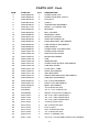
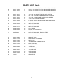
IB-400
Weighmobile
Owner’s Manual
0046-M023-O1 Rev I
05/00
CARDINAL SCALE MFG. CO.
PO Box 151 v Webb City, MO 64870
Ph: 417-673-4631 v Fax: 417-673-5001
www.detectoscale.com
Technical Support: Ph: 866-254-8261 v [email protected]
Printed in USA
2
Thank you for purchasing our DETECTO™
Model IB-400 Weighmobile. It has been
manufactured with quality and reliability at our
factory in Webb City, MO USA. This scale has
been tested before leaving our factory to insure
accuracy and dependability for years to come.
TABLE OF CONTENTS
Specifications . . . . . . . . . . . . . . . . . . . . . . . . . . . . . 1
Introduction . . . . . . . . . . . . . . . . . . . . . . . . . . . . . . . . 2
Assembly Instructions . . . . . . . . . . . . . . . . . . . . . 2
Weighing the Patient . . . . . . . . . . . . . . . . . . . . . . 3
When removing the scale from its packing,
inspect it for signs of damage, such as exterior
dents and scratches. Keep the carton and
packing material for return shipment if it should
become necessary. It is the responsibility of the
purchaser to file all claims for any damages or
loss incurred during transit, unless this
responsibility has been accepted by the seller
in its proposal.
Component Identification . . . . . . . . . . . . . . . . . . 4
Preventive Maintenance . . . . . . . . . . . . . . . . . . . 6
Service Information . . . . . . . . . . . . . . . . . . . . . . . . 6
Parts List . . . . . . . . . . . . . . . . . . . . . . . . . . . . . . . . . . 7
SERIAL NUMBER ___________________
DATE OF PURCHASE _______________
PURCHASED FROM ________________
__________________________________
__________________________________
This manual is provided to guide you through
installation, operation and maintenance of your
scale. Please read it thoroughly before
attempting to install or operate your IB-400 and
keep it handy for future reference.
ÜÜÜÜÜÜÜÜÜÜÜÜÜÜÜÜÜÜÜÜÜÜÜÜÜÜÜÜÜÜÜÜÜÜÜÜÜÜÜÜÜÜ
RETAIN THIS INFORMATION FOR FUTURE USE
PRECAUTIONS
Before using this instrument, read this
manual and pay special attention to all
"WARNING" symbols:
FCC COMPLIANCE STATEMENT WARNING!
This equipment generates, uses and can radiate
radio frequency and if not installed and used in
accordance with the instruction manual, may cause
interference to radio communications. It has been
tested and found to comply with the limits for a
Class A computing device pursuant to Subpart J of
Part 15 of FCC rules, which are designed to
provide reasonable protection against such
interference when operated in a commercial
environment. Operation of this equipment in a
residential area may cause interference in which
case the user will be responsible to take whatever
measures necessary to correct the interference.
IMPORTANT
SPECIFICATIONS
You may find the booklet "How to Identify and
Resolve Radio TV Interference Problems" prepared
by the Federal Communications Commission
helpful. It is available from the U.S. Government
Printing Office, Washington, D.C. 20402. Stock No.
001-000-00315-4.
ÜÜÜÜÜÜÜÜÜÜÜÜÜÜÜÜÜÜÜÜÜÜÜÜÜÜÜÜÜÜÜÜÜÜÜÜÜÜÜÜÜÜ
All rights reserved.
Reproduction or use, without
expressed written permission, of editorial or pictorial
content, in any manner, is prohibited. No patent liability is
assumed with respect to the use of the information
contained herein. While every precaution has been taken
in the preparation of this manual, the Seller assumes no
responsibility for errors or omissions. Neither is any
liability assumed for damages resulting from use of the
information contained herein. All instructions and
diagrams have been checked for accuracy and ease of
application; however, success and safety in working with
tools depend to a great extent upon the individual
accuracy, skill and caution. For this reason the Seller is
not able to guarantee the result of any procedure
contained herein. Nor can they assume responsibility for
any damage to property or injury to persons occasioned
from the procedures. Persons engaging the procedures
do so entirely at their own risk.
Capacity:
400 lbs (180 kg)
Resolution:
0.1 lb (0.05kg)
Display:
LCD digital display mounted
on Weighmobile, operating
from replaceable Alkaline,
Ni-Cad or NiMH batteries.
Refer to 758C Indicator
manual for battery operation.
Casters:
Four (4); full swivel, rear pair
locking
Lift
Mechanism:
Hydraulic
Stretcher:
(Adult)
Staph-Chek® 38" W x 72" L
Stretcher:
(Child)
Staph-Chek® 32" W x 48" L
Closed Overall 54"H x 22"W x 50"L
Dimensions:
1
Shipping
Weight:
280 lbs
Operating
Voltage:
9.0 VDC nominal
INTRODUCTION
The Detecto IB-400 Weighmobile provides a fast, easy and efficient method for weighing
bedridden patients. The IB-400 is easily operated by one person. Through its use, patient
weighing time will be reduced to a minimum. Operation of the scale can be quickly learned
using the following instructions and guidelines.
The Detecto IB-400 Weighmobile indicator is a completely self-contained, battery-powered unit
that can be programmed to automatically shutoff after one (1) to nine (9) minutes of non-use. It
can be powered for months by six (6) "C" size Alkaline, Ni-Cad or NiMH batteries and is
equipped with a low "BAT" indicator to alert the operator when the batteries are discharged.
The flame-retardant, anti-bacterial, self-deodorizing Staph-Check® stretcher is non-machine
washable / dryable and should only to be wiped clean using warm, soapy water and/or a mild
detergent and allowed to air dry.
Staph-Chek® is a registered trademark of Herculite Products, Inc.
ASSEMBLY INSTRUCTIONS
1. Unpack and remove all packing material.
2. Check for damaged parts.
3. Install batteries in indicator "C". Refer to the 758C Series Operation Manual,
8555-M167-O1 for detailed instructions.
4. Plug the coiled scale cable from the boom "F" into the 9-pin D shaped connector on the
rear panel of the indicator. Tighten the scale cable connector retaining screws to hold the
cable securely to the connector on the indicator. Refer to the 758C Series Operation
Manual for more information.
5. Pull down on hoop release rings "X" and hang stretcher hoops "J" in hoop brackets "T".
Patient stretcher "K" can now be attached to stretcher support hoop "J".
6. Turn on indicator to check battery charge.
It is now time to ready the hydraulic pump assembly:
7. Turn the cylinder "H" release valve clockwise to the fullest degree.
8. Move the pump handle "G" up and down slowly until the boom "F" reaches its highest
position.
9. Fully open the cylinder "H" release valve counterclockwise, and push the boom "F" down
as far as it will go.
10. Close the cylinder release valve, turning clockwise.
11. Raise the boom "F" to the approximate height at which it will be used.
Reference Figures No. 1 and 2 on pages 4 and 5 for component identification.
2
WEIGHING THE PATIENT
WARNING - This product is not intended for use in transporting patients!
It is to be used ONLY for weighing a patient. Failure to observe this warning may
result in serious injury to the patient and/or the Weighmobile operator.
1. Wheel scale to patient's bedside.
2. Remove stretcher "K" from carrier "M" and suspend it from stretcher support hooks "J".
3. On the indicator "C", press the ON key on the keypad, then press the ZERO key.
4. When indicator reads zero (0.0), remove stretcher from stretcher support hooks. The
indicator will show a negative weight equal to stretcher weight.
5. With patient lying flat in bed, roll and place stretcher alongside patient. Work stretcher
under patient by unrolling stretcher, much like changing a bed sheet.
6. The patient's weight must be centered as nearly as possible along the length of the
stretcher, so that when lifting, the patient remains in a horizontal position.
7. Roll scale so that base "A" is under bed, and stretcher support hoops "J" are suspended
directly over patient. Set brakes on rear wheels "P".
8. Widen base stance. To adjust base stance, face rear of scale and pivot adjust handle "L"
towards the column. Rotate handle unit until stance widens. Return handle to a vertical
position to engage lock pin. To return base to the narrow position, reverse above
procedure.
9. Turn the cylinder "H" release valve counterclockwise to the open position. When
stretcher support hooks "J" reach the mattress, return the release valve to the original
position.
10. Engage the stretcher support hooks "J" in the four (4) holes of the stretcher braces "N".
11. After closing the release valve, move the pump handle "G" up and down with slow strokes
of even pressure until the patient is about an inch above the mattress. Make sure that no
part of the patient or stretcher is touching any part of the bed or mattress.
12. When weight is stable, press the HOLD/RELEASE key to lock the displayed weight.
Note, that the weight displayed, will flash and remain locked until the HOLD/RELEASE
key is pressed again.
13. Lower patient by slowly opening release valve counterclockwise. When patient is back
on bed and stretcher support hooks "J" touch mattress, disengage hooks from stretcher
braces "N", raise Boom "F", release brakes on rear wheels "P" and remove scale from
bedside.
Caution: Open control valve SLOWLY to prevent sudden lowering of boom.
14. Remove stretcher from under patient. Replace stretcher in stretcher transport carrier "M",
and stretcher cup "R".
3
COMPONENT IDENTIFICATION
F
C
M
G
T
J
X
H
P
K
N
A
R
Figure No. 1
4
COMPONENT IDENTIFICATION
F
J
M
X
C
L
R
K
P
A
Figure No. 2
5
PREVENTIVE MAINTENANCE
The information presented below can save you time and trouble, and if adhered to, will prolong
the service and life of the Weighmobile.
1. Do not lift the boom by hand. Use only the pump.
2. A small amount of oil will accumulate around the piston from time to time. This should be
removed with a facial tissue.
3. Casters and axle bolts require inspection every sixty (60) days to be sure that the axle nuts
are tight and that the casters swivel and roll smoothly. A light grease (waterproof auto
lubricant) may be applied to the ball bearing swivel of the casters once a year, or more
frequently if the casters are exposed to extreme moisture conditions.
4. The hydraulic pump is factory sealed. If service is ever required, the pump unit must be
returned to the factory for repair. This is seldom necessary, but after many years of service,
the seals may require replacement. Do not attempt to open the hydraulic pump to obtain
local service. This will void the guarantee, and may result in damage and costly repair.
5. Periodically check and tighten all bolted connections and check that both "U" bolts are
securely fastened to the boom assembly.
IMPORTANT! Failure to maintain tightness of bolted connections may result in
injury to the patient and/or Weighmobile operator.
7. When transporting the Weighmobile between locations, use care in observing clearance
through doorways, etc. Severe collisions with the weighing assembly could result in
permanent damage to the weighing sensors. Also, when moving the Weighmobile through
doorways and corridors, insure that the stretcher is stored in the stretcher transport carrier.
NOTE: The lower eyebolts are secured by a special type of locknut and must
NOT be tightened or adjusted. Tightening will preload the weight sensor and
result in inaccurate readings or possible permanent damage.
SERVICE INFORMATION
The Detecto Weighmobile is designed and fabricated as a precision scale instrument. It is
comprised of four (4) major subassemblies that are functionally integrated and are most
efficiently serviced as a system or independently at the factory. In the event that factory repairs
are required, call the factory for service authorization. It is suggested that the inoperative
subassembly be tagged with a manila tag, bearing as much information as possible regarding
the nature of the problem. Refer to Operation Manual 8555-M167-O1 for questions regarding
the 758C indicator.
PROBLEM
SOLUTION
Weights grossly inaccurate.
Make sure patient is centered on stretcher and not
touching any part of the bed or mattress.
Display does not illuminate, or turns off soon
after being turned on.
Batteries may be discharged. If using Alkaline,
remove and replace. If using Ni-Cad or NiMH
batteries remove and recharge in external charger.
Weight reading does not change when applying
weight to stretcher or force to ends of support
cage.
Make certain coiled cable from boom is plugged into
connector on indicator and screws are tight.
Instrument is defective. Call factory for assistance.
Instrument reading drifts randomly.
Call factory for assistance.
Certain segments of the display do not illuminate. Call factory for assistance.
Display is "locked up" - either over range or
underrange.
This is usually due to weight transducer or cable
malfunction, and is difficult to resolve without special
equipment. Call factory for assistance.
6
PARTS LIST
6 22 67
63
12 13
25
54 70
19 21
4
5
24
17
26 27
71 75
7
10
18
65
3
31
64
9
15
30
2
14
16
33
69
29
68
Figure No. 3
7
8 11 20
23 28 60
62
PARTS LIST, Cont.
ITEM
PART NO.
QTY
DESCRIPTION
2
0046-B005-08
1
STRETCHER CUP
3
0046-B006-08
2
STRETCHER BAR, ADULT
4
0046-B018-08
2
EYE BOLT
5
0046-B019-08
2
U-BOLT
6
0046-B108-0A
1
TRIM BOARD ASSEMBLY
7
0046-B111-08
1
DECAL, CYLINDER TOP
8
0046-B200-08
5
BUSHING
9
0046-B249-08
1
BALL SOCKET
10
0046-B268-08
1
WARNING LABEL
11
0046-B431-08
1
SCRATCH GUARD
12
0046-B448-08
2
HOOP RETAINER PIN
13
0046-B450-08
2
HOOP BRACKET WELDMENT
14
0046-B455-08
1
CAM HANDLE WELDMENT
15
0046-B458-08
1
CAM HANDLE
16
0046-B468-08
1
STRETCHER CUP BRACKET
17
0046-C007-08
1
STRETCHER COVER
18
0046-C026-08
1
INSTRUCTION CARD
19
0046-C409-0A
1
BOOM WELDMENT
20
0046-C423-08
1
CAM
21
0046-C429-08
1
INNER BOOM
22
0046-C437-0A
1
STRETCHER SLEEVE WELDMENT
23
0046-C440-08
1
CAM BOX DOOR
24
0046-C447-08
1
LOAD CELL TUBE
25
0046-C465-0A
2
HOOP WELDMENT
26
0046-C471-08
1
758C BRACKET
27
0046-C467-0A
1
INDICATOR BRACKET WELDMENT
28
0046-D405-0A
1
CAM BOX WELDMENT
29
0046-D406-0A
1
LEFT LEG WELDMENT
30
0046-D407-0A
1
RIGHT LEG WELDMENT
31
0046-D408-0A
1
MAST WELDMENT
32
391RV204
2
1/4-20 ELASTIC NUT
33
409-B030
1
1/4" X 1 1/4" CLEVIS PIN
34
593GR986
1
SERIAL TAG WITH OVERLAY
35
6007-0054
2
3/8-16 X 2 HEX HEAD BOLT
36
6007-0120
4
1/2-13 X 1 HEX HEAD BOLT
37
6007-1016
1
1/2-13 X 3 HEX HEAD BOLT
38
6013-0025
4
10-32 ELASTIC NUT
39
6013-0070
4
3/8-16 ELASTIC NUT
40
6013-0379
4
5/16-24 NUT
41
6013-0410
5
5/16-18 ELASTIC NUT
42
6013-0438
5
1/2-13 ELASTIC NUT
43
6020-0015
3
5/32 X 1 SPRING PIN
44
6021-1126
2
1/4-20 X 1-3/4 SOCKET HEAD CAP SCREW
8
PARTS LIST, Cont.
45
6021-1171
5
10-24 X 3/4 SELF TAPPING HEX HEAD SCREW
46
6021-1236
1
3/8 X 1-1/4 SOCKET HEAD SHOULDER SCREW
47
6021-1237
1
3/8 X 2-1/2 SOCKET HEAD SHOULDER SCREW
48
6021-1239
1
3/8 X 2-1/4 SOCKET HEAD SHOULDER SCREW
49
6021-1401
4
1/4-20 X 1/2 SOCKET HEAD CAP SCREW
50
6021-1464
2
3/8-16 X 1-3/4 HEX HEAD MACHINE SCREW
51
6021-1497
4
1/4-20 X 1-1/8 SOCKET HEAD CAP SCREW
52
6021-2002
1
10-32 X 3/4 THUMB SCREW
53
6021-2069
2
#6 X 1/2 TRUSS HEAD SHEET METAL SCREW
54
6022-0028
2
SPRING
55
6024-0009
3
3/8 FLAT WASHER
56
6024-0012
6
1/2 FLAT WASHER
57
6024-0017
2
5/8 FLAT WASHER
58
6028-0094
2
SPLIT RING
59
6028-0095
2
5/8 X 5-1/2 CLEVIS PIN
60
60S43
1
SPRING
61
650RV26
4
5/8 FLAT WASHER, ZINC PLATED
62
6540-1070
2
FOAM HAND GRIP
63
6540-1078
4
1-1/4 SQUARE TUBING PLUG
64
6540-1080
1
HANDLE GRIP
65
6540-1119
1
HYDRAULIC CYLINDER
66
6540-1120
2
CAP PLUG
67
6540-1132
1
1-3/4 SQUARE TUBING PLUG
68
6540-1133
2
REAR CASTER
69
6540-1134
2
FRONT CASTER
70
6650-0085
2
1/4 E-RING
71
6680-1044
1
3/4 GROMMET
72
6680-1081
1
1/4 HUB CAP
73
6750-0015
2
3/8 BUSHING
74
6980-1035
4
1/4 BUSHING
75
758C
1
INDICATOR
9
GNED
I
S
E
D
I N U .S
TURED
AC
&
M ANUF
.
.A