1
____________________________ SIMSCRIPT III 3-D Graphics Manual ____________________________ CACI Copyright © 2010 CACI Products Company. All rights reserved. No part of this publication may be reproduced by any means without written permission from CACI. For product information or technical support contact: CACI Products Company 1455 Frazee Road, Suite 700 San Diego, CA 92108 Phone: (619) 881-5806 Email: [email protected] The information in this publication is believed to be accurate in all respects. However, CACI cannot assume the responsibility for any consequences resulting from the use thereof. The information contained herein is subject to change. Revisions to this publication or new editions of it may be issued to incorporate such change. ii Table of Contents Table of Contents................................................................................................................ 3 Preface................................................................................................................................. 5 1. Introduction................................................................................................................. 7 1.1 A Typical 3d Graphics Program ............................................................................... 8 1.2 Example code for a typical 3d graphics program ................................................... 10 1.3 Class hierarchy........................................................................................................ 12 2. The “scene-graph” ........................................................................................................ 14 2.1 The “3dworld” ........................................................................................................ 14 2.2 Setting the location of a node.................................................................................. 15 2.3 Setting the orientation of a node ............................................................................. 16 2.4 Shifting the position of a node ................................................................................ 17 2.5 Rotating a node ....................................................................................................... 17 2.4 Scaling a node ......................................................................................................... 18 2.5 Complete Scene-graph example ............................................................................. 18 3.1 Camera location and orientation ............................................................................. 22 3.2 Setting up the viewing plane................................................................................... 24 3.3 Adding a 3dcamera to the scene-graph................................................................... 25 3.4 Viewports and multiple cameras............................................................................. 26 3.5 Tracking a moving object with the 3dcamera......................................................... 27 4. Lighting up a scene-graph............................................................................................. 31 4.1 Determining the “variety” of lighting ..................................................................... 31 4.2 Ambient, Diffuse and Specular light ...................................................................... 32 4.3 Setting up the lighting using the 3dlight ................................................................. 34 5. Loading graphics files via Models................................................................................ 37 5.1 Reading in the 3dmodel from a file ........................................................................ 37 5.2 Linking a 3dmodel instance to a 3dnode instance .................................................. 37 5.4 Copying the scene-graph of a 3dmodel .................................................................. 38 5.5 Locating named sub-components ........................................................................... 39 5.6 Deriving from sub-components .............................................................................. 39 5.7 Misc. 3dmodel options............................................................................................ 43 6. Geometry....................................................................................................................... 45 6.1 Using the 3dgraphic class. ...................................................................................... 45 6.2 Surface geometry .................................................................................................... 46 6.4 Surface appearance ................................................................................................. 53 6.5 Surface texture mapping ......................................................................................... 54 6.6 Drawing points and lines ........................................................................................ 57 6.7: Drawing points....................................................................................................... 60 6.8 Text ......................................................................................................................... 62 Bitmapped fonts ........................................................................................................ 63 6.9 Updating the graphic............................................................................................... 65 6.8 Classes with retained geometry .............................................................................. 66 7. Surfaces, Textures and Materials.................................................................................. 67 7.1 Setting the color and shininess of a surface ............................................................ 67 7.2 Texture mapping and raster images ........................................................................ 68 3 7.3 Front and back side visibility.................................................................................. 71 7.4 Using instances of 3dmaterial................................................................................. 72 8. User Input.................................................................................................................. 75 8.1 Mouse, keyboard and window frame interaction.................................................... 75 8.2 Mouse events .......................................................................................................... 76 Value ......................................................................................................................... 76 Value ......................................................................................................................... 76 Value ......................................................................................................................... 77 Value ......................................................................................................................... 77 Value ......................................................................................................................... 77 8.3 Keyboard input........................................................................................................ 79 8.4 Selecting a node in the scene-graph........................................................................ 80 9. Animation and Simulation ............................................................................................ 84 9.1 Frame Based Animation ......................................................................................... 84 9.2 Time scaling............................................................................................................ 84 9.3 Automatic motion and the motion_set.................................................................... 85 9.4 Moving Car Example.............................................................................................. 86 9.5 Achieving customized motion ................................................................................ 87 10. 3d Class reference ....................................................................................................... 93 3dbox (lineage: 3dbox -> 3dshape -> 3dgraphic -> 3dnode)........................................ 93 3dcamera (lineage: 3dcamera -> 3dnode)..................................................................... 93 3dcone (lineage: 3dcone -> 3dshape -> 3dgraphic -> 3dnode) .................................... 95 3dcylinder (lineage: 3dcylinder -> 3dshape -> 3dgraphic -> 3dnode) ......................... 95 3dellipse (lineage: 3dellipse -> 3dshape -> 3dgraphic -> 3dnode)............................... 95 3devent (lineage: 3devent -> gui.m:guievent) .............................................................. 96 3dfaces (lineage: 3dfaces -> 3dgraphic -> 3dnode)...................................................... 97 3dgraphic (lineage: 3dgraphic -> 3dnode).................................................................. 102 3dlight (lineage: 3dlight -> 3dnode) ........................................................................... 105 3dlines (lineage: 3dlines -> 3dgraphic -> 3dnode) ..................................................... 106 3dmaterial ................................................................................................................... 108 3dmodel....................................................................................................................... 110 3dnode......................................................................................................................... 113 3dpoints (lineage: 3dpoints -> 3dgraphic -> 3dnode)................................................. 118 3drectangle (lineage: 3dshapes.m:drectangle -> 3dshape -> 3dgraphic -> 3dnode) .. 119 3dshape (lineage: 3dshapes.m:3dshape -> 3dgraphic -> 3dnode) .............................. 120 3dsphere (lineage: 3dsphere -> 3dshape -> 3dgraphic -> 3dnode)............................. 120 3dtext (lineage: 3dtext -> 3dgraphic -> 3dnode) ........................................................ 120 Bitmapped fonts ...................................................................................................... 121 3dwindow (lineage: 3dwindow -> gui.m:guiitem) ..................................................... 122 3dworld ....................................................................................................................... 124 4 Preface This document contains information on CACI's new SIMSCRIPT III, Modular ObjectOriented Simulation Language, designed as a superset of the widely used SIMSCRIPT II.5 system for building high-fidelity simulation models. It focuses on the description of the SIMSCRIPT III 3-D Graphics. CACI publishes a series of manuals that describe the SIMSCRIPT III Programming Language, SIMSCRIPT III Object - Oriented 2-D and 3-D Graphics and SIMSCRIPT III development environment SimStudio. All documentation is available on SIMSCRIPT WEB site http://www.simscript.com/products/simscript_manuals.html • SIMSCRIPT III 3-D Graphics Reference Manual — this manual – is a detailed description of the SIMSCRIPT III 3-D graphical objects available in 3d.m module. • SIMSCRIPT III User’s Manual – A detailed description of the SIMSCRIPT III development environment: usage of SIMSCRIPT III Compiler and the symbolic debugger from the SIMSCRIPT development studio, Simstudio, and from the Command-line interface. • SIMSCRIPT III Programming Manual – A short description of the programming language and a set of programming examples. • SIMSCRIPT III Reference Manual - A complete description of the SIMSCRIPT III programming language constructs in alphabetic order. Graphics constructs are described in the SIMSCRIPT III Graphics Manual. Since SIMSCRIPT III is a superset of SIMSCRIPT II.5, a series of manuals and text books for SIMSCRIPT II.5 language, Simulation Graphics, Development environment, Data Base connectivity, Combined Discrete-Continuous Simulation, can be used for additional information: • SIMSCRIPT II.5 Simulation Graphics User’s Manual — A detailed description of the presentation graphics and animation environment for SIMSCRIPT II.5 • SIMSCRIPT II.5 Data Base Connectivity (SDBC) User’s Manual — A description of the SIMSCRIPT II.5 API for Data Base connectivity using ODBC • SIMSCRIPT II.5 Operating System Interface — A description of the SIMSCRIPT II.5 APIs for Operating System Services • Introduction to Combined Discrete-Continuous Simulation using SIMSCRIPT II.5 — A description of SIMSCRIPT II.5 unique capability for modeling combined discrete-continuous simulations. • SIMSCRIPT II.5 Programming Language — A description of the programming 5 techniques used in SIMSCRIPT II.5. • SIMSCRIPT II.5 Reference Handbook — A complete description of the SIMSCRIPT II.5 programming language, without graphics constructs. • Introduction to Simulation using SIMSCRIPT II.5 — A book: An introduction to simulation with several simple SIMSCRIPT II.5 examples. • Building Simulation Models with SIMSCRIPT II.5 —A book: An introduction to building simulation models with SIMSCRIPT II.5 with examples. The SIMSCRIPT language and its implementations are proprietary software products of the CACI Products Company. Distribution, maintenance, and documentation of the SIMSCRIPT language and compilers are available exclusively from CACI. Free Trial Offer SIMSCRIPT III is available on a free trial basis. We provide everything needed for a complete evaluation on your computer. There is no risk to you. Training Courses Training courses in SIMSCRIPT III are scheduled on a recurring basis in the following locations: San Diego, California Washington, D.C. On-site instruction is available. Contact CACI for details. For information on free trials or training, please contact the following: CACI Products Company 1455 Frazee Road, suite 700 San Diego, California 92108 Telephone: (619) 881-5806 www.simscript.com 6 1. Introduction The Simscript III 3d graphics package is an object-oriented wrapper around the OpenGL toolkit. The public preamble 3d.m.sim contains the basic class descriptions that allow the programmer to create windows containing 3d graphical scenes. “Camera” and “light” objects can be created to implement realistic scenes in an object-oriented fashion. Hierarchical scene-graphs allow the programmer to specify graphical objects (called “nodes”) as containing other objects (positioning and orientation of a “container” node will automatically affect the position and orientation of the sub-nodes it contains. Each node in the scene graph represents a visible graphic in the window. The node is implemented with the 3dnode class. In order to see the nodes in the scene-graph a “Camera” is necessary. Each 3d program must create at least one camera and orient it properly in order to view the scene-graph. Multiple cameras are allowed, and there viewports can be overlapped or tiled on the canvas of a 3d window. A camera can also be attached as part of a scene-graph allowing it to move or rotate with its parent node. A 3dcamera class implements the camera. Multiple light sources are allowed in a Simscript 3d graphics program. A “Light” can be created a positioned and oriented with respect to the scene. Light objects are also part of the scene-graph and are implemented using the 3dlight class. A “Model” represents a specific shape that can be displayed multiple times in the same window at different locations and orientations. Methods of this class allow geometry and properties for various surfaces and lines to be specified. “Graphic” items are attached to the scene-graph that reference “model” objects. Models are implemented with the 3dmodel class. A “Material” provides a covering of 3d surfaces. The material can have a distinct color and shininess. Texture mapping is supported via the material object. The texture is stored in a 2d raster image file such as a Windows Bitmap or (“.BMP”) file or a Targa Graphics file (“.TGA”). 2d Coordinates specified with the 3d vertices identify the position in the raster image file that is to map to the surface. Surface materials are implemented with the 3dmaterial class. A “Graphic” is a node in the scene-graph that provides the base class for all visible 3d objects whose geometry is defined at runtime. Sub-classes of the graphic object are provided that support various types of lines and surfaces. The graphic object can also be sub-classed and its “draw” method overridden. This allows customized surface types to be created and rendered by the application. The graphic is implemented with the 3dgraphic class. The “World” is used as the root of the scene-graph. Several worlds can appear in the same window allowing such things as control panels, graphs, heads up displays, or any 7 other such visual aids that are separate from the 3d scene, but appear in the same window. Graphics in multiple worlds will not interleave but overlap regardless of the distance from viewer. The 3dworld class is used to implement a world. Nodes contained in the scene can have animated motion that is linked to elapsing simulation time. 1.1 A Typical 3d Graphics Program A typical 3d graphical simulation will display many graphical objects, which may or may not be moving with respect to simulation time. Light sources and cameras must be created. To create such a program, the following steps should be performed: 1) Write customized drawing code (if necessary). a) Define sub-classes of 3dgraphic in the preamble and override the “draw” method. b) In the implementation of “draw” make calls to begin_drawing and end_drawing. c) Between begin_drawing and end_drawing, make calls to 3dgraphic class methods to define the vertices, normal vectors, texture coordinates and materials of the shape. 2) Write event handling code (if necessary). a) If keyboard input, mouse input, or window resize handling is needed, define in the preamble a subclass of 3dwindow and override its “action” method. b) Implement the “action” method by writing code to inspect the attributes of the “3devent” instance passed as its argument and perform the necessary processing. 3) Create windows and worlds. a) For each window that is needed, create an instance of a 3dwindow object. Call methods to set size, position and title. b) Create instances of the 3dworld object. Usually only one world is needed, unless you are implementing a control panel, heads up display, or the application requires multi-layered graphics. c) File 3dworld instances into the “world_set” owned by the 3dwindow object. d) If a hierarchy (or groupings of objects) is needed, create instances of the 3dnode object. File them into the node_set owned by the 3dworld in which they are to be used. They can otherwise be filed into the node_set owned by another node. 4) Create camera(s) a) For each view of the scene, create an instance of a 3dcamera object. 8 b) Set the location and orientation of the camera so that it is some distance from the scene, but is pointing at the scene. If necessary, call other methods to customize the view. c) File instances into the “camera_set” owned by the 3dworld showing the view. d) A 3dcamera can also be attached to a 3dnode allowing its position and orientation to be determined by the parent node. If necessary, the 3dcamera object can ALSO be filed into a “node_set”. 5) Create light(s) (if necessary). a) For each light illuminating the scene, create an instance of a 3dlight object. b) Set the location of the light appropriately. For spot lights it may be necessary to set the orientation also. c) File instances into the “light_set” owned by the 3dworld showing the view. d) A 3dlight can also be attached to a 3dnode allowing its position and orientation to be determined by the parent node. If necessary file the light into a “node_set”. 6) Create models (if necessary). a) For each unique model that is used in the 3dworld, create a instance of a 3dmodel object. b) If the model geometry is stored in a 3dStudio (.3ds) file, a AutoCAD (.dxf) file or a SIMGRAPHICS II (.sg2) file, call the “read” method to read the file. c) File each 3dmodel instance in the “model_set” owned by the 3dworld. 7) Create materials. a) Create an instance of a 3dmaterial object for each unique color or texture used in the program. (Materials defined offline (in a .3ds file) are created automatically when 3dmodel’read is called.) b) Set the color, shininess, and texture_name attributes. c) File each 3dmaterial instance into the “material_set” owned by 3dworld. 8) Create other graphical objects for the simulation. a) Create instances of sub-classes of 3dgraphic such as 3dfaces, 3dlines, 3dpoints, to represent objects in the simulation. Create instances of the subclasses of 3dgraphic described in step 1. b) Create instances of 3dnode to represent a model on-screen. Assign the “model” attribute so that the 3dnode will draw this model at its location. c) Some objects may have a “material” attribute that needs to be assigned. d) File these instances into the “node_set” owned by the 3dworld, or by another 3dnode. 9) Call the display method of the 3dwindow. This will show the window. 9 10) Before starting the simulation, activate the “3dwindow’animate” method. This method will keep refreshing the window as often as possible as the simulation runs. Don’t forget to set “timescale.v”. 1.2 Example code for a typical 3d graphics program ''Example of a initializing a 3d graphics application ''Requires ford.3ds model file preamble including the 3d.m subsystems begin class my_window every my_window is a 3dwindow and overrides the action end define the_car as a 3dnode reference variable end ''2) Write event handling code overriding the 3dwindow'action method method my_window'action(event) if id(event) = 3devent'_close stop always if id(event) = 3devent'_key_down select case key_code(event) case 3devent'_right_key call rotate_y(the_car)(2) case 3devent'_left_key call rotate_y(the_car)(-2) case 3devent'_up_key call rotate_x(the_car)(2) case 3devent'_down_key call rotate_x(the_car)(-2) case 3devent'_home_key call move(the_car)(0.0, 0.0, 5.0) case 3devent'_end_key call move(the_car)(0.0, 0.0, -5.0 ) default endselect always return with 0 end main define define define define define window as a my_window reference variable world as a 3dworld reference variable camera as a 3dcamera reference variable light as a 3dlight reference variable model as a 3dmodel reference variable ''3) Create windows, worlds, and groups 10 create window let title(window) = "Use the arrow, home, and end keys to move the model" create world file this world in world_set(window) ''4) create camera(s) create camera call set_orientation(camera)(0.0, 0.0, -1.0, 0.0, 1.0, 0.0) call set_location(camera)(0.0, 0.0, 100.0) file this camera in camera_set(world) ''5) create light(s) create light let ambient_color(light) = color'rgb(0.4, 0.4, 0.4) let diffuse_color(light) = color'rgb(1.0, 1.0, 1.0) call set_location(light)(0.0, 500.0, 500.0) file this light in light_set(world) ''6) create model(s) create model call read(model)("ford.3ds", "") file this model in model_set(world) ''7) create material(s) ''(materials for this example are created automatically when '' model is read) ''8) create objects used in the simulation '' a) Create instances of 3dnode to represent the model on-screen. '' Assign the "model" attribute to link the model to the 3dnode. create the_car let model(the_car) = model file this the_car in node_set(world) ''9) Call the display method of the 3dwindow. ''This will show the window. call display(window) ''10) Before starting the simulation, activate the 3dwindow’animate ''method. This method will keep refreshing the window as often as ''possible as the simulation runs. Don’t forget to set timescale.v. activate a animate(window)(10000) now let timescale.v = 100 start simulation end 11 Figure 1.1: Example 3d graphics program showing a 3d model of a 1963 ford 1.3 Class hierarchy There are many classes that can be used to implement 3d graphics the full hierarchy for the ones found in the 3d.m subsystem is shown in Figure 1.2. Figure 1.3 shows classes found in 3dshapes.m. 12 Figure 1.2: 3d.m classes Figure 1.3: 3dshapes.m classes 13 2. The “scene-graph” To write a SIMSCRIPT 3d graphics program, you must make use of “windows”, “worlds” and “nodes”. The nodes are used to compose the hierarchy of the “scenegraph”. Every 3d graphics program must construct at least one scene-graph to represent the 3d objects and background. Each “node” in this graph is represented with an instance of a 3dnode object. The 3dnode object is filed into a node_set, which is owned by another “parent” 3dnode. 2.1 The “3dworld” The root of a scene-graph must always be an instance of a 3dworld object. The 3dworld class also owns a node_set for child nodes to be filed into. Every 3dworld instance is filed into a world_set owned by a 3dwindow object. The 3dwindow object represents GUI window and can be moved and resized like other windows on the computer screen. It can contain multiple 3dworlds and acts as the root of all scene-graphs to be displayed on its canvas. Basically, the rule is that every object that is to be made visible (with the exception of the 3dwindow) must be filed into an appropriate set or it will not be shown. The figure below shows a diagram of a scene-graph. Figure 2.1: A typical scene graph for a tank and a battlefield. The code for creating this scene-graph would look something like this: 14 Define window as a 3dwindow reference variable Define battlefield, control_panel as a 3dworld reference variable Define tank, body, turret, housing, cannon, terrain, ground, obstacles As 3dnode reference variables … create window, battlefield, control_panel create tank, body, turret, housing, cannon, terrain, ground, obstacles file file file file file file file file file file this this this this this this this this this this housing in node_set(turret) cannon in node_set(turret) turret in node_set(tank) body in node_set(tank) tank in node_set(battlefield) ground in node_set(terrain) obstacles in node_set(terrain) terrain in node_set(battlefield) battlefield in world_set(window) control_panel in world_set(window) The 3dworld also acts as a container for other objects that are employed by nodes in the attached scene-graph. The table below lists the various sets owned by a 3dworld object: Set name camera_set light_set material_set model_set node_set Member 3dcamera 3dlight 3dmaterial 3dmodel 3dnode Description cameras used to show the scene-graph. light sources in the scene. materials used by 3dnodes in the scene-graph. models used by nodes in the scene-graph. forms the scene-graph. 2.2 Setting the location of a node Properties of the 3dnode are its location and orientation. The location_x, location_y, and location_y attributes represent the x, y, and z coordinates of the node’s position with respect to its owner node in the scene-graph. Right-handed use of these attributes is allowed, but the set_location method should be used to set these attributes. Suppose the simulation was to show a ferry shuttling passengers. Some of the code that might be used to build the scene-graph and position the objects is: ''put all passengers 'on the ferry' by filing ''into the node set owned by the_ferry instance For I = 1 to 100 File this passenger(i) in node_set(the_ferry) ''set z location of the ferry. Passengers will move with the ferry! let location_z(the_ferry) = 1000.0 ''set a passengers position with respect to ferry call set_location(passenger(2))(2.5, 0.0, 34.9) 15 2.3 Setting the orientation of a node The orientation of a node can be defined by 2 vectors, “forward” and “up” (See Figure 22). The forward vector indicated the direction of the local z-axis relative to the owner node in the scene-graph. By default, the forward vector is (0.0, 0.0, 1.0) which would point a node in the same direction as its owner node. The “up” vector is the local y-axis relative to the node’s owner in the scene_graph. By default, this is (0.0, 1.0, 0.0). The local x-axis is computed automatically by taking the cross product of these vectors. Figure 2.2: Forward and Up vectors. (In this case the positive X axis would point away from the viewer). The attributes forward_x, forward_y, forward_z, up_x, up_y and up_z can be used on the right, but should not be assigned individually. Both forward and up vectors must always be normalized and orthogonal to each other. The set_orientation method allows both the forward and up vectors to be assigned. For example, set_orientation could be used to point a passenger in the opposite direction of the “ferry”. Call set_orientation(passenger(2))(0.0, 0.0, -1.0, 0.0, 1.0, 0.0) ''forward_x, forward_y, forward_z, up_x, up_y, up_z Another method called set_forward allows the forward direction to be specified alone, while the “up” vector is computed automatically. This vector is computed in such a way that its projection onto the positive y-axis is maximized. (for 3dcameras, this will prevent the view from tilting assuming the “floor” of the scene lies in the x-z plane) define set_forward as a method given 3 double arguments ''forward_x, forward_y, forward_z Another method that may be useful for setting the orientation of a 3dnode is the aim method. Calling the aim method will set the forward direction of the node so that it “points at” a given location. The location should be in global coordinates; non-local to the 3dnode. (The 3dworld’get_location method can be used to convert a location from local to global coordinates). When aim is used on a sub-component, the (local) orientation (forward and up vectors) of the sub-component will be modified so that the sub-component points (with its positive z-axis) at the given location. The aim method 16 can only be called after the 3dnode has been filed into the node_set. Since the aim method uses the orientation and location of parent nodes, it should be called after all the location of all parent (grand-parent, etc.) nodes have been initialized. ''make a passenger turn to look at a spot on the shoreline Call aim(passenger(2))(45000, 20.0, -20000) ''target_x, target_y, target_z 2.4 Shifting the position of a node The set_orientation and set_forward methods expect vectors that are oriented with respect to the node’s owner in the scene-graph (or the 3dworld if the 3dnode is filed in 3dworld’node_set). Likewise, the set_location method provides coordinates with respect to the coordinate system defined by node’s owner in the scene-graph. However, in some cases it may be easier to position the node with respect to its own coordinate system. The move method will shift the position of a node by a movement right, up and forward with respect to its own axes. The node’s location will be moved along its local x-axis, y-axis, and z-axis by the three given values. ''move passenger(2) 10 units forward call move(passenger(2))(0.0, 0.0, 10.0) ''dx, dy, dz 2.5 Rotating a node It is also possible to “spin” a 3dnode on one of its three local axes. The rotate_x, rotate_y, and rotate_z methods will do just that. Each method takes an angle (in degrees) as an argument and spins the 3dnode by that amount about the local (not owner) axis. These methods are similar to the move method in that they take “delta” values instead of absolute values. For example, if an airplane is pointed forward along its positive z axis, call the rotate_x method will pitch up or down. In this case the local Y and Z axes are rotated, but the X axis will remain unchanged. Calling the rotate_y method will yaw about its y axis. Calling the rotate_z method will “roll” the airplane. define rotate_x, rotate_y, rotate_z as method given 1 double argument ''angle in degrees The local axes of a node are rotated with the node itself. For example, in Figure 10, a box is first rotated about the z-axis the moved by 100.0 units in the “Y” direction (up). 17 Figure 2.3: Calling rotate_z followed by move. 2.4 Scaling a node The scale method will modify size of the node. A scaling factor is provided for each axis and, as with move and rotate scaling is performed along the local axes. Each axis is scaled by the given scale factor (a value of “1.0” will not change the axis). Consider a process method to simulate an animated explosion. The scale method is called in a loop to animate the size change of the explosion. The wait statement allows a small amount of time to elapse. Process method explosion'explode define I as a integer variable for i = 1 to 100 do call scale(1.1, 1.1, 1.1) ''sx, sy, sz (width, height, depth) wait 0.1 units loop end 2.5 Complete Scene-graph example In the following example, a scene-graph will be created showing some traffic cones and a tank. The tank will maneuver through the cones as the simulation runs. Preamble including the 3d.m, 3dshapes.m subsystem begin class tank every tank is a 3dnode and has 18 a speed, a spin_rate, a movement process method, overrides the motion define speed, spin_rate as double variables end define window as a 3dwindow reference variable end process method tank'movement define spin, forward as double variables define _spin_speed = 20, _forward_speed=2 as constants open unit 1 for input, name is "example2.dat" use unit 1 for input let eof.v = 1 while eof.v = 1 and visible(window) <> 0 do read spin, forward '' rotate the tank let spin_rate = _spin_speed * sign.f(spin) wait abs.f(spin) / _spin_speed units let spin_rate = 0 ''move the tank forward let speed = _forward_speed wait abs.f(forward) / speed units let speed = 0.0 loop close unit 1 end ''our motion method will be called automatically as simulation time ''advances method tank'motion(dt) call 3dnode'motion(dt) call rotate_y(dt * spin_rate) call move(0.0, 0.0, dt * speed) end main define define define define define define define define define world as a 3dworld reference variable camera as a 3dcamera reference variable light as a 3dlight reference variable tank_model, cone_model as a 3dmodel reference variable background as 3dnode reference variables the_tank as a tank reference variable cones as a 2-dim 3dnode reference variable _num_rows_cones=11, _num_cols_cones=11 as a constant i,j as an integer variable ''create the window create window let title(window) = "Example 2: using a simple 3dnode scene-graph" ''create the world create world file this world in world_set(window) ''create camera, place it along positive z axis but 19 ''point it down the negative z direction create camera call set_perspective(camera)(90.0, 1.0, 5.0, 115.0, 1) call set_forward(camera)(0.0, 0.0, -1.0) call set_location(camera)(0.0, 4.0, 60.0) file this camera in camera_set(world) ''create a light source and point it in the same direction as the camera create light call set_forward(light)(0.0, 0.0, -1.0) file this light in light_set(world) ''create a background node to hold the objects create background file this background in node_set(world) ''add to "root" of scene-graph ''create the one model for the tank create tank_model call read(tank_model)("tank.3ds", "") file tank_model in model_set(world) ''create the tank node create the_tank let model(the_tank) = tank_model file the_tank in node_set(world) file the_tank in motion_set ''add to "root" of scene-graph ''create the model for the cone create cone_model call read(cone_model)("cone.3ds", "") file this cone_model in model_set(world) ''create many cones and space them out reserve cones as _num_cols_cones by _num_rows_cones for i = 1 to _num_rows_cones for j = 1 to _num_cols_cones do create cones(i,j) let model(cones(i,j)) = cone_model ''cones share the same model call set_location(cones(i,j))(i * 10 - 55.0, 0.0, j * 10 -55.0) file this cones(i,j) in node_set(background) ''add node to scene-graph loop call display(window) ''bring up the main window and show everything activate a movement(the_tank) now ''our process method activate a animate(window)(10000) now ''tell window to show animation let timescale.v = 10 ''10/100 real seconds per unit of time start simulation end 20 Figure 2.4: Example 2 – A tank maneuvering through traffic cones. 21 3. Cameras and Lights Every 3d graphics program must have at least one camera to view the scene-graph. A “light” is also needed to illuminate the scene-graph. Cameras are implemented with the “3dcamera” class while lights are represented by the “3dlight” class. Basically, setting up each camera involves: a. Creating an instance of a 3dcamera object. b. Set the location and direction of the camera so that the scene-graph will be in view by calling 3dcamera’set_location and 3dcamera’set_forward. c. Set the view angle, aspect ratio, and near and far clipping planes by calling 3dcamera’set_perspective. d. Set the portion of the window canvas that the view from the camera should encompass by calling 3dcamera’set_viewport. e. File the camera in the camera_set owned by the 3dworld that the camera is to see. f. If the camera is to be part of the scene-graph, file it into the node_set owned by a parent 3dnode. As an example, the initialization code for the camera in the above “example #2 is as follows: ''create camera, place it along positive z axis but ''point it down the negative z direction create camera call set_perspective(camera)(90.0, 1.0, 0.1, 1000.0, 1) call set_forward(camera)(0.0, 0.0, -1.0) call set_location(camera)(0.0, 4.0, 60.0) file this camera in camera_set(world) 3.1 Camera location and orientation Since the 3dcamera is derived from 3dnode, it inherits the methods that allow orientation and position to be specified. These methods are: set_location(x,y,z) ''sets the location_x, location_y and location_y attributes. If ''the camera is attached to a scene-graph, this location is with ''respect to the parent node. set_orientation(fx, fy, fz, ux, uy, uz) ''set the forward vector <fx,fy,fz> and the up vector <ux,uy,uz> set_forward(fx,fy,fz) ''sets the forward vector <fx,fy,fz>. The camera will “point” in ''this direction aim(x,y,z) ''causes the camera to point at the given target location. ''The target location is specified in global “world” ''coordinates rotate(ax,ay,az,degrees) ''rotates the camera about the given axis by the given number ''of degrees. 22 rotate_x(degrees), rotate_y(degrees), rotate_z(degrees) ''spins the camera about its local x, y, or z axis by the ''given number of degrees As and example we will analyze how the view was set up in Example 2. In this case, the “world” was oriented with respect to the viewer as follows: a. Its positive X axis is pointing to the right. b. Its positive Y axis (up vector) is pointing straight up. c. Its and its positive Z axis is pointing at the viewer. The default “up” vector is to point straight up, so it is not necessary to set this—in other words calling the set_forward method is sufficient. If the positive Z axis is to point toward the viewer, the camera should point in the opposite direction, or along the negative Z axis. call set_forward(my_camera)(0.0, 0.0, -1.0) Figure 3.1: Camera orientation for Example 2. Now that we have defined how the coordinate axes are oriented with respect to the viewer, the position of the camera must be specified. But there must first be some idea of how big the scene-graph is in terms of coordinate space—so that we know how far away from the scene to place the camera from the scene. We must also know where the scene is in the coordinate space. In Example 2, the scene is geographically centered at the (0,0,0) point. And since our camera is pointing along the negative Z axis, it must be placed along the positive Z axis with respect to the scene-graph. The scene is specified in meters. The tank moves about an area which is about 100 by 100 meters and is located in the x-z plane. Placing the camera about 10 meters beyond the boundaries of the lot will allow most of the scene to be in view. Since the lot is centered about (0,0,0) we place the camera at z=+60. Also, in order to see the traffic cones that are far away, the camera should be placed a few meters up in the air. 23 call set_location(camera)(0.0, 4.0, 60.0) 3.2 Setting up the viewing plane The next consideration is for setting up the camera’s projection. Two methods are available for doing this: set_perspective and set_orthographic. Usually, you will want to use a perspective projection. The set_perspective method sets the cameras near and far clipping planes, as well as the aspect ratio of its width to height and the angle of view. define set_perspective as a method given 1 double argument, ''perspective_angle > 0.0, < 180.0 degrees 1 double argument, ''perspective_ratio. 2 double arguments, ''perspective_near, perspective_far 1 integer argument ''perspective_autosize Figure 3.2: Using the set_perspective method. The perspective_angle parameter is specified in degrees and represents that angle of the field of view in the y direction (see figure 3.2). The perspective_ratio is the ratio of the width of the viewing plane to its height. Values below 1.0 will cause the image to appear compressed vertically. perspective_ratio values greater than 1 will compress the view horizontally. However, if the perspective_autosize parameter is “1”, the perspective ratio will be determined based on window canvas size. In this case the perspective_ratio argument will be ignored. Basically, turning on the perspective_autosize will avoid “compressing” the scene either vertically or horizontally regardless of how the user sizes the window. For setting up the camera in Example 2, a perspective angle of 90 degrees is a good start. The camera is located at z+60 with the nearest edge of the parking lot at z+50 meters. A near clipping plane of +5 is adequate. The farthest edge of the lot is at z-50 meters, a distance of 110 meters. The far clipping plane of +115 will allow the entire lot and tank to be seen. To avoid distorting the aspect ratio, we will pass “1” to the perspective_autosize argument. call set_perspective(camera)(90.0, 1.0, 5.0, 115.0, 1) 24 The use of the set_orthographic method is not common. When viewing an orthographic projection, there is no depth information provided. In other words, an object that is far away from the camera will be rendered to be the same size as when it is close to the camera. The arguments to set_orthographic define the clipping volume—or the coordinate boundaries of the box that encloses everything that we want to view. These units are relative to the location of the camera. define set_orthographic as a method given 2 double arguments, ''left, right 2 double arguments, ''bottom, top 2 double arguments, ''far, near 1 integer argument ''1=> adjust size automatically after window resize Figure 3.3: Using the set_orthographic method. It would be possible to modify Example 2 to use an orthographic transformation. The call to “set_perspective” is replaced with a call to the “set_orthographic” method. To simplify things we will place the camera in the center of the parking lot and allow it to “see” 50 meters to its left, its right, its front and its back. create camera call set_orthographic(camera)(-50, 50, 0, 100, -50, 50, 1) call set_location(camera)(0.0, 0.0, 0.0) call set_forward(camera)(0.0, 0.0, -1.0) file this camera in camera_set(world) 3.3 Adding a 3dcamera to the scene-graph Since the 3dcamera object is derived from 3dnode it can optionally be part of the scenegraph. If a camera is filed into the node_set owned by a parent node, it will move and rotate with the parent automatically. If for example you wanted to see the view out of the locomotive of a moving train, the 3dcamera object could be filed into the node_set of the locomotive’s 3dnode. The camera would then be located and oriented with respect to 25 the locomotive and not the ground. This would naturally show the view from the train as it moves and turns along its track. Suppose we wanted to modify Example 2 to show the view from the “tanks” perspective instead of a static view from the parking lot. Adding the following code after the tank is created could do this: file camera in node_set(the_tank) call set_location(camera)(0.0, 4.0, 0.0) ''location relative to tank’s center call set_forward(camera)(0.0, 0.0, 1.0) ''point camera in same dir. as tank (Example 3 contains the code to do this). 3.4 Viewports and multiple cameras By default, the view seen by each camera will encompass the entire canvas of the window to which it is attached. However, the set_viewport method may be called to assign a rectangular box to which the view is mapped. define set_viewport as a method given 2 integer arguments, ''x, y in pixels. 2 integer arguments, ''width, height pixels. 1 integer argument ''1=>size viewport to window canvas The dimensions of the view are given in pixels with (0,0) located at the lower left corner of the window canvas (see Figure 3.4). Having viewports enables the use of multiple camera objects. The view from each camera can be mapped into a separate area of the canvas. Figure 3.4: Using the set_viewport method. Since the viewport dimensions are specified in pixels, in order to know what the width and height parameter values to set_viewport should be we usually need to know the 26 dimensions of the window canvas. This can be obtained by reading the canvas_width and canvas_height attributes of the 3dwindow class. Unfortunately these values are not updated until the window becomes visible. Therefore the window must be displayed before the viewports are initialized. The last parameter to the set_viewport method is a flag to indicate if the viewport dimensions should be automatically adjusted as the window is resized. The viewports are modified so that they occupy the same percentage of window space after the resize operation. As such, if zero is passed for this flag and the user resizes the window to make it very small, part of the viewport may disappear. Suppose that we want to modify Example 2 to show the view from multiple camera objects. We will create a second camera and attach it to the tank itself. The view from the tank is to appear on the left side of the canvas while the view from the parking lot appears on the right side. Basically we will be setting up each camera as in Example 2, but will be adding the code call set_viewport(tank_camera)(0, 0, canvas_width(window)/2, canvas_height(window), 1) call set_viewport(lot_camera)(canvas_width(window)/2, 0, canvas_width(window)/2, canvas_height(window), 1) 3.5 Tracking a moving object with the 3dcamera Another attribute of the 3dcamera called tracked_node can be assigned allowing the camera to automatically “track” or point at another node in the scene-graph. In other words, the tracked node will always appear in the center of the camera’s viewport regardless of its position. As the node is tracked, the camera will align its local “up” vector with the global Y axis (in order to keep the view from “tilting”). Example 2 can easily be modified to allow the camera to track the moving tank by adding one line of code: Let tracked_node(lot_camera) = the_tank The fully “updated” version of Example 2 (which we call call Example 3) is below: ''Example 3, updated 'tank' program Preamble including the 3d.m, 3dshapes.m subsystem begin class tank every tank is a 3dnode and has a speed, a spin_rate, a movement process method, overrides the motion define speed, spin_rate as double variables end define window as a 3dwindow reference variable 27 end process method tank'movement define spin, forward as double variables define _spin_speed = 20, _forward_speed=2 as constants open unit 1 for input, name is "example2.dat" use unit 1 for input let eof.v = 1 while eof.v = 1 and visible(window) <> 0 do read spin, forward '' rotate the tank let spin_rate = _spin_speed * sign.f(spin) wait abs.f(spin) / _spin_speed units let spin_rate = 0 ''move the tank forward let speed = _forward_speed wait abs.f(forward) / speed units let speed = 0.0 loop close unit 1 end ''our motion method will be called automatically as simulation time ''advances method tank'motion(dt) call 3dnode'motion(dt) call rotate_y(dt * spin_rate) call move(0.0, 0.0, dt * speed) end main define define define define define define define define define world as a 3dworld reference variable tank_camera, lot_camera as 3dcamera reference variables light as a 3dlight reference variable tank_model, cone_model as a 3dmodel reference variable background as 3dnode reference variables the_tank as a tank reference variable cones as a 2-dim 3dnode reference variable _num_rows_cones=11, _num_cols_cones=11 as a constant i,j as an integer variable ''create the window create window let title(window) = "Example 3: Using cameras to show different views of the same scene" call display(window) ''display the window now so that we know the ''size of the canvas! ''create the world create world file this world in world_set(window) ''create a light source and point it in the same direction as the camera create light call set_forward(light)(0.0, 0.0, -1.0) file this light in light_set(world) ''create a background node to hold the objects 28 create background file this background in node_set(world) ''add to "root" of scene-graph ''create the one model for the tank create tank_model call read(tank_model)("tank.3ds", "") file tank_model in model_set(world) ''create the tank node create the_tank let model(the_tank) = tank_model file the_tank in node_set(world) file the_tank in motion_set ''add to "root" of scene-graph ''create the "tank" camera. It will be attached to the tank's 3dnode ''so that it will show the view out of the tank create tank_camera call set_perspective(tank_camera)(60.0, 1.0, 0.1, 115.0, 1) call set_forward(tank_camera)(0.0, 0.0, 1.0) call set_location(tank_camera)(0.0, 4.0, 0.0) call set_viewport(tank_camera)(0, 0, canvas_width(window)/2, canvas_height(window), 1) file tank_camera in camera_set(world) file tank_camera in node_set(the_tank) ''create the "lot" camera, place it along positive z axis but ''point it down the negative z direction create lot_camera call set_perspective(lot_camera)(60.0, 1.0, 0.1, 115.0, 1) call set_forward(lot_camera)(0.0, 0.0, -1.0) call set_location(lot_camera)(0.0, 4.0, 60.0) call set_viewport(lot_camera)(canvas_width(window)/2, 0, canvas_width(window)/2, canvas_height(window), 1) file this lot_camera in camera_set(world) ''make the lot_camera "track" the tank let tracked_node(lot_camera) = the_tank ''create the model for the cone create cone_model call read(cone_model)("cone.3ds", "") file this cone_model in model_set(world) ''create many cones and space them out reserve cones as _num_cols_cones by _num_rows_cones for i = 1 to _num_rows_cones for j = 1 to _num_cols_cones do create cones(i,j) let model(cones(i,j)) = cone_model ''cones share the same model call set_location(cones(i,j))(i * 10 - 55.0, 0.0, j * 10 -55.0) file this cones(i,j) in node_set(background) ''add node to scene-graph loop activate a movement(the_tank) now ''our process method activate a animate(window)(10000) now ''tell window to show animation let timescale.v = 10 ''10/100 real seconds per unit of time start simulation end 29 Figure 3.5: Example 3, Tank program updated to include two viewports and tracking. 30 4. Lighting up a scene-graph As all objects in the scene-graph as smooth-shaded, light source(s) are needed to apply the shading. A light source can be added to the 3dworld by creating one or more instances of a 3dlight object. The 3dlight class is derived from 3dnode and can reside in in a scene-graph much the same way that a 3dcamer can. Lights are positioned and oriented using methods inherited from 3dnode. 4.1 Determining the “variety” of lighting In addition, the 3dlight class adds a variety attribute which defines the characteristic nature of the light source. The three varieties are _directional, _positional, and _spot: Value for variety 3dlight’_directional 3dlight’_positional 3dlight’_spot Description Light has no fixed position, but emanates uniformly from a single direction. The set_forward method can be used to set the direction vector. The set_location method has no effect. This light is useful for mimicking sunlight, or light from a far away source. This is the default variety of 3dlight. Light emanates uniformly in all directions from a single source. The set_location method can be used to set the location of the source. This variety has both direction and positional characteristics. It is shown as a cone of light emanating from a fixed point (set_location method) and traveling in a certain direction (set_forward method) The spot_cutoff attribute is used to set the angle (in degrees). See figure 4.1. Figure 4.1: The spot_cutoff attribute A good example of the use of “positional” lighting would be the SIMSCRIPT III “parking lot” demo. This program sets up a parking lot simulation at night. Lamp-posts are positioned at strategic locations around the parking lot. A 3dlight object is located at 31 the top of each lamp-post. The variety attributes are assigned the 3dlight’_positional value. The cars are illuminated from different angles and from different light sources as they move through the lot, which creates a realistic effect (See Figure 4.2). Figure 4.2: Three positional lights used in the parking lot demo. 4.2 Ambient, Diffuse and Specular light When light strikes the surface of an object, it is reflected based upon the properties of the surface material, and on the normal vector of the surface in relation to the light’s direction. Surface normals can be specified along with the geometry of a shape and this is described later. For now we will assume that the program will be using a 3dmodel that specifies the correct normal vectors for each surface. For each 3dlight we can define how it interacts with the surface that is reflecting it. Relative amounts of ambient, diffuse and specular light can be specified by assigning the ambient_color, diffuse_color and specular_color attributes. These types of light are described below: 32 Ambient This type of light is non-directional and non-positional (location and orientation is ignored). Ambient light will illuminate all surfaces ignoring normal vectors. The ambient term is used simply to keep shadows from turning pitch black. The relative intensity of ambient light can be set by assigning the ambient_color attribute to an rgb value returned from the gui.m:color’rgb class method. If less ambient light is required, darker colors should be used. For example, setting ambient_color to color’rgb(0.25, 0.25, 0.25) will provide a 1/4th intensity of ambient light. Diffuse Diffuse light is reflected from a surface in all directions. The amount of reflected light is determined by the “diffuse” color of surface material (see 3dmaterial). Rough surfaces should have a relatively bright diffuse_color attribute. Both diffuse and specular light allows objects to be shaded based on surface normal vectors. Surface elements with normals pointing at the light source will be illuminated while surfaces with normals orthogonal to the light source’s direction will not. The diffuse_color attribute determines the color and intensity of diffuse light. Specular Specular light is reflected from a surface in mostly one direction. Shiny surfaces reflect more of the specular light than rough surfaces. The amount of reflected light is determined by the “specular” color of surface material (see 3dmaterial). Surface elements with normals pointing at the light source will be illuminated while surfaces with normals orthogonal to the light source’s direction will not. The specular_color attribute determines the color and intensity of this light. All color related attributes defined in the 3d.m subsystem are specified in terms of an rgb triple. This is an integer returned from the “color’rgb” class method which is found in the gui.m subsystem. The color’rgb class function takes three double parameters as the percentage of RED, GREEN, and BLUE in the color (all in the range [0,1]). Predefined colors are defined in the color class also. For example, to set specular color to a particular shade of yellow: Let specular_color(my_light) = color'rgb(0.9, 0.9, 0.0) Or to set specular color to red: Let specular_color(my_light) = color'_red The witnesses effect of the light striking a 3d object and reflecting into the camera depends on the ambient, diffuse and specular colors attributes of not only the 3dlight but also of the 3dmaterial (which represents the surface properties of the object, and is described later). If specular (shiny) effects are to be seen, usually both the material and light must have a high degree of specular color. Figure 4.3 shows how specular light can 33 affect the appearance of a surface. The scene is illuminated with a directional light from above (I.e. set_forward(0.0, -1.0, 0.0) and with the specular_color attribute of the 3dlight set to color’_white. As far as the toruses go, the ambient and diffuse color for all is set to a shade of purple or color'rgb(0.8, 0.4, 0.7). However, the specular_color attribute for toruses on the right is greater that those on the left. Figure 4.3: Objects on the left have more specular color and appear shiny. 4.3 Setting up the lighting using the 3dlight To summarize, setting up lighting involved the following set of steps: a. Create instance(s) of a 3dlight object. b. Optionally set the location the direction of the light using the set_location and set_forward methods inherited from 3dnode. 34 c. Set the type of light by assigning the variety attribute. (_positional, _directional, _spot). d. Assign the ambient_color, diffuse_color, and specular_color attributes in accordance with the desired properties. e. File the 3dlight object instance into the light_set owned by the 3dworld that will contain the light. f. Optionally file the light into a node_set if it is to be attached to an object in the scene-graph. In examples 2 and 3 above, a single directional light source is used. The light is pointed away from the viewer—along the negative Z axis by calling the set_forward method. (If the light were to be directed along the positive Z axis, the objects in the foreground would be “back-lit” and difficult to see). The default ambient, diffuse and specular color attributes are used. ''create a light source and point it in the same direction as the camera create light call set_forward(light)(0.0, 0.0, -1.0) file this light in light_set(world) We can make the lighting more interesting in this example by creating a “spot” variety light and automatically pointing it at the tank as it moves around. For the spot light, a new class called tank_spotter is derived from 3dlight. To achieve the automated tracking, the motion method is overridden. (This method is described later – it is called automatically as simulation time is updated). The code to declare the subclass of 3dlight is: begin class tank_spotter every tank_spotter is a 3dlight and overrides the motion end The implementation code for motion is: method tank_spotter'motion(dt) ''point the light at the tank call aim(location_x(the_tank), location_y(the_tank), location_z(the_tank)) end To initialize the light its variety attribute is assigned to spot and we must provide its location. Also, since a spot light is being used, we should define the spot_cutoff attribute—it will be set to 15 degrees. Lastly, in order for the light’s motion method to be called automatically, it must be filed into the motion_set (described later). ''create the tank_spotter light and position it near the camera create light let variety(light) = 3dlight'_spot let spot_cutoff(light) = 15 ''degrees-defines the light cone call set_location(light)(0.0, 6.0, 60.0) file this light in light_set(world) file this light in motion_set 35 Figure 4.4: Using a spot light to track the tank. 36 5. Loading graphics files via Models 3d dimensional objects are easily maneuvered using the SIMSCRIPT 3d graphics functionality, but creating three dimentional cars, tanks, and airplanes by program code can be a long process. For this reason, it is much easier to load predefined objects from a graphics file format such as Autodesk’s “3ds”. These 3d graphics can be created using a 3d “point and click” editor, or can be purchased online. In any case, SIMSCRIPT 3d graphics supports the loading of two well known 3d graphics file formats – 3ds and dxf. 5.1 Reading in the 3dmodel from a file The 3d surfaces and geometry shown in the 3dworld can be defined in one of two ways. The 3dgraphic and its subclasses allow the application to specify the geometry and materials and runtime. The 3dmodel class allows the surfaces and materials to be loaded from a file. Basically, a single instance of a 3dmodel is created for each separate 3d file. The read method loads the contents of the file creating surfaces and materials, which are saved in memory. define read as a method given 1 text argument, ''file name including .3ds, .dxf, .sg2 extension 1 text argument ''name of model in the file (.sg2 files only) The first argument specifies the name of the file. Currently, the file must be in either autodesk 3dStudio or “.3ds” format (the extension is required), AutoCAD dxf format, or SIMGRAPHICS II “.sg2” format. For .sg2 files, the name of the model within the file is provided in the second argument. Also, each 3dmodel instance must be filed into a model_set owned by the 3dworld, which will show the model. From Example 1, we load the model of the 3d car from the file named “ford.3ds” as follows: define model as a 3dmodel reference variable . . . create model call read(model)("ford.3ds", "") file this model in model_set(world) 5.2 Linking a 3dmodel instance to a 3dnode instance 37 The 3dmodel class is not derived from 3dnode and therefore cannot be shown in a window directly. The 3dmodel instance can be assigned to the model attribute of a 3dnode. This will provide a link from the image of the 3dmodel to the 3dnode. Many instances of 3dnode can reference the same 3dmodel instance. This scheme allows a single model to be drawn in different locations and orientations in the world. (See Figure 5-1). Figure 5.1: Three 3dnode instances using the same model of a jet. 5.4 Copying the scene-graph of a 3dmodel In some cases, the application may require individual images of a 3dmodel to appear differently. In this case the same model cannot be shared—each image is different and requires its own separate scene-graph. For example, if many “tanks” were to be displayed, each turret will have a different orientation. In this case, instead of assigning the model attribute, the 3dnode’load method would be called. This method will make copies of each sub-component and place the nodes into the appropriate node_set. Define tank1, tank2, as tank reference variables Define the_model as a 3dmodel reference variable Create tank1, tank2, the_model File the_model in model_set(the_world) File tank1 in node_set(the_world) File tank2 in node_set(the_world) Call read(the_model)("tank.3ds", "") Call load(tank1)(the_model) Call load(tank2)(the_model) 38 Figure 5.2: Calling the load method instead of assigning the model attribute. 5.5 Locating named sub-components Models may be designed in the 3d editor to have well defined components. In the previous example, the ‘tank’ model has a component that was named “turret1” in the editor for the purpose of being rotated indepedantly with respect to the tank. The turret sub-component may in turn have a ‘gun’ sub-component. The application may need access to these sub-components at runtime (i.e. rotate the turret, move the gun in and out when it fires, etc). If sub-components like this are defined in the graphics editor, they will be preserved when model is loaded in the application. The node_set owned by the 3dmodel will contain these components. Both the 3dnode and 3dmodel classes define a find method that can be called to perform a depth-first search for a sub-component, provided that the component has been given a name in the graphics editor. Let turret(tank1) = find(tank1)("turret1") Let turret(tank2) = find(tank2)("turret1") 5.6 Deriving from sub-components Suppose the application wanted to represent the turret sub-component of a tank using an object derived from 3dnode (instead of the 3dnode base class). In this case the 3dmodel would be sub-classed and its create_component method overridden. define create_component as a ''virtual'' 3dnode reference method given 1 text argument, ''name of the component 1 text argument ''name of required class ''This method is called by the system during the execution of the ''"read" method to create a new sub-node component. ''The name given to the component in the model file ''is provided in argument 1. By default this method will create a ''instance of the class named by argument 2, but can be overridden to ''create a sub-class of arg 2. 39 Create_component is called automatically for each separate component that is created at the time a 3dmodel is read. Overriding this method allows you to create and return the correct sub-class that should represent the component. In the above example, create_component would be implemented to create and return a “turret” object if the first argument specified the name assigned to the turret component in the graphics editor. See below. method tank_model'create_component(component_name, class_name) define my_turret as a turret reference variable if component_name = "turret1" and class_name = "3dnode" create a turret called my_turret return with my_turret otherwise return with 3dmodel'create_component(component_name, class_name) end When the 3dnode’load() method is used, it will make copies of all components in the model. Individual attributes are copied by an internal call to the copy_attributes method. Therefore, if a component is subclassed as above, and the load method is to be used, the sub-class must override this method if it defines attributes that need to be copied with the rest of the components. In our tank example, suppose the “turret” class defines attributes “azimuth” and “attitude” that are initializes in the model. We want these values to be propagated when turret is copied (via the load method). Begin class turret Every turret is a 3dnode and has A azimuth, An attitude, and Overrides the copy_attributes Define azimuth, attitude as double variables End The copy_attributes method’s implementation would look like this: method turret'copy_attributes(node) define p as a pointer variable define original_turret as a turret reference variable let p = node ''necessary due to original prototyping let original_turret = p let azimuth = azimuth(original_turret) let attitude = attitude(original_turret) call 3dnode'copy_attributes(node) end 40 In the next example, a tank model is used that has its turret represented by a subcomponent called “turret1”. Three sub-classes are defined in the preamble: tank_model, a subclass of 3dmodel, tank a subclass of 3dnode, and turret another subclass of 3dnode. The tank_model class will override create_components to create and instance of a turret object when “turret1” is passed as the component name. Both the tank and turret subclasses will define a process method called movement. Each process method will be implemented in a unique fashion to allow simultaneous but different motion. Preamble including the 3d.m, 3dshapes.m subsystem begin class tank_model every tank_model is a 3dmodel and overrides the create_component end begin class tank every tank is a 3dnode and has a speed, a spin_rate, a forward process method, a spin process method, a movement process method, overrides the motion define speed, spin_rate as double variables define spin, forward as process methods given 1 double argument end begin class turret every turret is a 3dnode and has a spin_rate, a spin process method, a movement process method, overrides the motion define spin_rate as a double variable define spin as a process method given 1 double argument end define window as a 3dwindow reference variable end method tank_model'create_component(component_name, class_name) define my_turret as a turret reference variable if component_name = "turret1" and class_name = "3dnode" create a turret called my_turret return with my_turret otherwise return with 3dmodel'create_component(component_name, class_name) end process method tank'forward(distance) define _forward_speed=2 as a constants let speed = _forward_speed wait abs.f(distance) / speed units let speed = 0.0 end process method tank'spin(angle) 41 define _spin_speed = 20 as a constants let spin_rate = _spin_speed * sign.f(angle) wait abs.f(angle) / _spin_speed units let spin_rate = 0 end process call call call call call call end method tank'movement forward(40) spin(180) forward(40) spin(90) forward(40) spin(90) process method turret'spin(angle) define _spin_speed = 10 as a constant let spin_rate = _spin_speed * sign.f(angle) wait abs.f(angle) / _spin_speed units let spin_rate = 0 end process call wait call wait call call wait call end method turret'movement spin(45) 2.0 units spin(-90) 1.0 units spin(180) spin(-30) 1.0 units spin(-40) ''our motion method will be called as simulation time advances method tank'motion(dt) call 3dnode'motion(dt) call rotate_y(dt * spin_rate) call move(0.0, 0.0, dt * speed) end method turret'motion(dt) call rotate_y(dt * spin_rate) end main define define define define define define define world as a 3dworld reference variable camera as a 3dcamera reference variable light as a 3dlight reference variable tank_model as a tank_model reference variable the_tank as a tank reference variable the_turret as a turret reference variable p as a pointer variable ''create the window create window let title(window) = "Example 5: Accessing sub-components of a 3dmodel" ''create the world create world file this world in world_set(window) 42 ''create camera, place it along positive z axis but ''point it down the negative z direction create camera call set_perspective(camera)(90.0, 1.0, 5.0, 115.0, 1) call set_forward(camera)(0.0, 0.0, -1.0) call set_location(camera)(0.0, 4.0, 60.0) file this camera in camera_set(world) ''create a light source and point it in the same direction as the camera create light call set_forward(light)(0.0, 0.0, -1.0) file this light in light_set(world) ''create the one model for the tank create tank_model call read(tank_model)("tank.3ds", "") file tank_model in model_set(world) ''create the tank node create the_tank call load(the_tank)(tank_model) ''copy components of tank to node let p = find(the_tank)("turret1") ''locate the "turret1" node let the_turret = p file the_tank in node_set(world) ''add to "root" of scene-graph file the_tank in motion_set file the_turret in motion_set call display(window) ''bring up the main window and show everything activate a movement(the_tank) now activate a movement(the_turret) now ''our process method activate a animate(window)(10000) now ''tell window to show animation let timescale.v = 50 ''50/100 real seconds per unit of time start simulation end 5.7 Misc. 3dmodel options There are a couple more options regarding the 3dmodel that can be set before the model is read from the file. They are _smoothing, and _cache_model. The options are set via a left handed use of the enabled method. For example: define the_model as a 3dmodel reference variable … let enabled(the_model)(3dmodel'_smoothing) = 1 ''turn on smoothing let enabled(the_model)(3dmodel'_smoothing) = 0 ''turn off smoothing The _smoothing option will cause normal vectors to be recomputed at the time the model is read from the file. This will give the surfaces in the model a smooth appearance. It is off (0) by default. 43 The _cache_model option, if on, will cause the runtime library to create an internal “call list” for the model at the time a 3dnode which references it (via the model attribute) is first drawn. For the case of multiple 3dnode objects referencing the same static model, this will improve performance. This option is not relevant if the load method is used to link the 3dnode to the model. After a model is read, its size can be determined if necessary. The get_bounding_box method can be called to get the dimensions of a model in the x, y and z directions. define get_bounding_box as a method yielding 3 double arguments, ''(xlo,ylo,zlo) 3 double arguments ''(xhi,yhi,zhi) ''Computes the smallest 3d box that will enclose the model ''Must be called after "read" to be effective. Instances of 3dmodel must be filed into the model_set owned by the 3dworld in which the model is to appear. This must be done before the window is displayed. Materials used in the model are automatically filed into the material_set owned by 3dmodel when the 3dmodel’read method is called. 44 6. Geometry Often times parts of a 3d scene cannot be stored in a .3ds or .dxf “3dmodel” file. If it is the case that the geometry is not known exactly until runtime, the programmer must write code required to construct this geometry. SIMSCRIPT III provides several classes that allow this. The 3dgraphic is the base class for all objects whose geometry is defined by program code, and not by offline models stored in a file. This class is derived from 3dnode and is part of the scene-graph. Since 3dgraphic is derived from 3dnode, instances must be filed into a node_set (owned by either the 3dworld or by another 3dnode attached to a 3dworld). The 3d.m and 3dshapes.m subsystems provide several classes derived from 3dgraphic that can be useful for constructing various 3d objects (see below). Class name 3dgraphic Description Can be used to draw any type of shape. 3dfaces 3dlines 3dpoints 3dtext 3dbox 3dcone 3dcylinder 3dellipse Tessellated surface, (triangles, quads) Line segments in 3d space Single points in 3d space 2d text in 3d space Found in 3dshapes.m. Cubes, Simple cone shape. Simple cylinder shape. 2d circle, arc, pie or ellipse in 3d space 3drectangle 3dsphere 2d rectangle in 3d space Simple sphere shape Geometry attributes Override draw method draw_normal draw_texture_coordinate draw_vertex points, normals attributes points, width attributes points, size attributes string, width, height, font width, height, depth length, radius attributes length, radius attributes radius_x, radius_y, start_angle, stop_angle height, width radius 6.1 Using the 3dgraphic class. Occasionally, there are cases where the exact shape is not known until runtime. For example, a simulation shown a 3d terrain landscape may not know the geographical area to display until runtime. Even then, the coordinates of the “hills and valleys” may reside in a data file which must be decoded and the vertex information extracted or computed. We can handle this case using the 3dgraphic class. Geometry and surface materials are specified by sub-classing 3dgraphic and overriding the draw method. The draw method is called automatically when the system needs to have the 3dgraphic object rendered. (Calling the 3dwindow’display method will invoke 45 this method. Draw may also be called as a result of event handling). The draw method should be programmed to make calls to begin_drawing and end_drawing class methods to define each surface. After the call to begin_drawing, calls to class methods such as draw_normal, draw_texture_coordinate, and draw_vertex allow geometry to be specified for the surface. A call to end_drawing will mark the end of the geometry description started by begin_drawing. We will refer to this as a “drawing block”. There can be multiple drawing blocks defined in a single draw method. It is also possible to sub-class the 3dgraphic and override the draw method to “add” geometry. Nested drawing blocks are not allowed and will be flagged as a runtime error. There are several formats of geometry that can be specified in a drawing block. A “format” argument is passed to the begin_drawing method. The 3dgraphic class provides to following predefined constants that can be passed to begin_drawing. (The formats are described in detail later). Constant _points _lines _line_loop _line_strip _triangles _triangle_strip _triangle_fan _quads _quad_strip _polygon Format of Geometry Draw dots in 3d space. Each call to draw_vertex adds a dot. Each 2 successive vertices defines a line segment. Each vertex is connected to the next with the first connected to last. Each vertex is connected to the next. Each successive group of 3 vertices defines a triangle For each index n > 2 a triangle is defined by vertex at n-2, n-1 and n in counter-clockwise order. Sometimes this is called the “triangular mesh” or just “mesh”. For each index n > 2 a triangle is defined by vertex at n, n-1 and 1. Each successive group of 4 vertices defines a quadrilateral face. For each 2 indices n, n-1, a new quadrilateral is composed of vertices at n-3, n-1, n, n-2 in counter-clockwise order The outline of the polygon is defined by vertices. Again, the vertices for front facing polygons should be arranged in a counterclockwise order. 6.2 Surface geometry The surface of a shape in 3d is composed of small by planar faces that are interconnected. Round shapes that have smaller but more numerous faces will appear more detailed, but could take longer to render. Calls to the draw_vertex are placed inside a drawing block with the (x,y,z) values passed as arguments. Each call adds a new coordinate to the shape. A “normal vector” is perpendicular to the surface that is being drawn. If a normal vector is known, it can be specified by calling draw_normal. The normal vector specified will apply to subsequent vertices defined by draw_vertex. 46 Figure 6.1: Normal vectors To construct a 2d surface, one of the following predefined constants must be passed to begin_drawing: _triangles, _triangle_strip, _triangle_fan, _quads, or _polygon. Using the _triangles format will draw a separate triangle for each successive group of three vertices. As a rule of thumb, the vertices should be given in a counter-clockwise ordering if the normal vector points outward. Figure 6.2: _triangles format. The __triangle_strip format is sometime referred to as a “triangular mesh” or just “mesh”. It can be used to construct surfaces composed of interconnected triangles. Each call to draw_vertex will add a new triangle to the shape using the two previous coordinates given by draw_vertex. 47 Figure 6.3: _triangle_strip format. When using the _triangle_fan format, draw_vertex will add a new triangle using the first vertex and the previous vertex. This format can be useful for drawing circular shapes. Figure 6.4: Triangle fan. Surfaces composed of quads or 4-point planar regions can be defined. When using the _quads format, each group of 4 vertices defines a new quadrilateral face. 48 Figure 6.5: _quads format. Much like the “triangle strip” a quad strip can also be constructed. Each two successive vertices will add a new quad using the two previous vertices for the face. Figure 6.6: _quad_strip format. A simple polygon can also be created. The polygon must not have any concave portions or it may not be rendered correctly. The outline of the polygon is defined by successive calls to draw_vertex. Again, the points for front facing polygons should be arranged in a counter-clockwise ordering. 49 Figure 6.7: _polygon format. In the following example we will develop a new shape to represent a torus. The code to construct this doughnut shaped object will be entered into the overridden draw method that is inherited from the 3dgraphic class. The actual code to draw the torus will, in a loop, construct successive cylindrical rings that run in a circle along the shape of the torus. A “begin_drawing / end_drawing block will construct each ring as a _quad_strip. A normal vector is defined for each vertex. This is computed as the vector originating from the center of the current ring to the current vertex. Figure 6.8: A torus composed of rings made of quad strips. 50 Sub-classing the 3dgraphic class will allow us to add additional attributes that parameterize the torus, such as the major and minor radii, and the number of facets. The complete code is shown below: '' Example 7 a 3d torus preamble for the toruses system including the 3d.m subsystems begin class torus every torus is a 3dgraphic and has a material, a numMajor, a numMinor, a minorRadius, a majorRadius, and overrides the draw define material as a 3dmaterial reference variable define numMajor, numMinor as integer variables define minorRadius, majorRadius as double variables end end ''this method is called automatically. We will provide the code needed ''to draw a torus method torus'draw define nx, ny, nz as double variables define a0, a1, x0, y0, x1, y1 as double variables define b, c, r, z, majorStep, minorStep as double variables define i, j as integer variables let majorStep = 2.0*pi.c / numMajor let minorStep = 2.0*pi.c / numMinor call set_material(material) for i=0 do a0 = a1 = x0 = y0 = x1 = y1 = to numMajor-1 i * majorStep a0 + majorStep cos.f(a0) sin.f(a0) cos.f(a1) sin.f(a1) call begin_drawing(_quad_strip) for j=0 to numMinor do b = j * minorStep c = cos.f(b) r = minorRadius * c + majorRadius z = minorRadius * sin.f(b) ''First point call 3d.m:vector_normalize(x0*c,y0*c,z/minorRadius) yielding nx,ny,nz call draw_normal(nx, ny, nz) call draw_vertex(x0*r, y0*r, z) call 3d.m:vector_normalize(x1*c,y1*c,z/minorRadius) yielding nx,ny,nz call draw_normal(nx, ny, nz) call draw_vertex(x1*r, y1*r, z) loop 51 call end_drawing loop end main define define define define define window as a 3dwindow reference variable world as a 3dworld reference variable camera as a 3dcamera reference variable light as a 3dlight reference variable torus as a torus reference variable ''create the window create window let title(window) = "Example 7: A torus" ''create the world create world file this world in world_set(window) ''create a camera 3 units out, pointed at the origin create camera call set_perspective(camera)(60.0, 1.0, 0.1, 100.0, 1) call set_forward(camera)(0.0, 0.0, -1.0) call set_location(camera)(0.0, 0.0, 3.0) file this camera in camera_set(world) ''create our torus and set its size and detail parameters create a torus let minorRadius(torus) = .3 let majorRadius(torus) = .7 let numMinor(torus) = 37 let numMajor(torus) = 61 ''create a "red" material for torus's surface create a material(torus) let ambient_color(material(torus)) = color'rgb(0.2, 0.0, 0.0) let diffuse_color(material(torus)) = color'_red let specular_color(material(torus)) = color'_white let shininess(material(torus)) = 1.0 file this material(torus) in material_set(world) ''save the torus in the "world" file this torus in node_set(world) ''create a light from above, set its color create light let diffuse_color(light) = color'rgb(0.8, 0.8, 0.8) call set_orientation(light)(0.0, -1.0, 0.0, 1.0, 0.0, 0.0) file this light in light_set(world) call display(window) ''show every thing let timescale.v = 100 ''1 second per 1 unit simulated time activate a animate(window)(10000) now start simulation end 52 Figure 6.9: Torus drawn using the _quad_strip format. 6.4 Surface appearance 3dgraphic has class methods that can be called to define the properties of the surface. The set_color method can be used to set the color or, if called before draw_vertex, can set the color applied to individual vertices. define set_color as a method given 1 integer argument, ''_front, _back, or _front_and_back 1 integer argument, ''_ambient, _diffuse, _specular 1 integer ''color'' argument ''color (color'rgb(r,g,b)) The first argument indicates which side the color should be applied to, and must be one of the constants _front, _back or _front_and_back. The second argument gives the type of lighting, _ambient, _diffuse, or _specular that should reflect the given color (see 3dlight). The third argument is the color value obtained from the gui.m:color’rgb class. Attributes of the 3dmaterial object (colors and texture) can be applied to the 3dgraphic as well. The set_material method should be called before begin_drawing and takes a 3dmaterial instance as an argument. This instance must be filed in the 3dworld'material_set at initialization. define set_material as a method given 53 1 3dmaterial reference argument ''pointer to material The shininess of the surface (used for specular lighting) is set by calling the set_shininess class method. define set_shininess as a method given 1 integer argument, ''_front, _back, or _front_and_back 1 double argument ''shininess (0.0 to 1.0) The first argument must be one of the constants _front, _back, or _front_and_back. The second “shininess” argument must be a value between 0.0 and 1.0 (see 3dlight). By default, both the front and back sides of a surface are visible. In some cases, back or front side of an object is never seen. Faster rendering can be achieved for single sided drawings by defining which side is to be made visible. The set_visibility method can be called to accomplish this. The method call must be made before the call to begin_drawing. define set_visibility as a method given 1 integer argument ''_front, _back or _front_and_back Individual edges for surfaces specified by calls to draw_vertex are normally visible. For some edges such as those on the interior of a complicated shape, this visibility can lead to unwanted artifacts when the 3dgraphic is displayed. The set_edge_visibility method can be used to hide or show future edges added to the shape by draw_vertex. define set_edge_visibility as a method given 1 integer ''boolean'' argument ''0=>invisible, 1=>visible ''specifies visibility of future edges of a face 6.5 Surface texture mapping Texture mapping can be applied to surfaces created in a drawing block. The draw_texture_coordinate method can be called to map the vertex (specified by draw_vertex) to a 2d texture coordinate (texture mapping is explained in more detail later). The previous example could be modified to wrap a texture over the surface of the torus. The image that will be mapped is that of a soda can label (saved in the file “cocacola.bmp”). The surface will be parameterized to the (s,t) coordinate space of used for texture mapping whose domain is s => [0,1] and t => [0,1]. (0,0 is the lower left corner of the 2d image and (1,1) is the upper right corner. ) For each call to draw_vertex a corresponding call to draw_texture_coordinate is added. Also the texture_name attribute of the 3dmaterial used to set the surface color will be assigned to “cocacola.bmp”. 54 We will also modify the color of the material used for the torus. The 2d image file will provide the color information, and since we don’t want that color to be modified, _white will be used for the diffuse color and a dark gray for the ambient color. The new example code is shown below with the modified and new color colored red. '' Example 8: a texture mapped 3d torus preamble for the toruses system including the 3d.m subsystems begin class torus every torus is a 3dgraphic and has a material, a numMajor, a numMinor, a minorRadius, a majorRadius, and overrides the draw define material as a 3dmaterial reference variable define numMajor, numMinor as integer variables define minorRadius, majorRadius as double variables end end ''this method is called automatically. We will provide the code needed ''to draw a torus method torus'draw define nx, ny, nz as double variables define a0, a1, x0, y0, x1, y1 as double variables define b, c, r, z, majorStep, minorStep as double variables define i, j as integer variables let majorStep = 2.0*pi.c / numMajor let minorStep = 2.0*pi.c / numMinor call set_material(material) for i=0 do a0 = a1 = x0 = y0 = x1 = y1 = to numMajor-1 i * majorStep a0 + majorStep cos.f(a0) sin.f(a0) cos.f(a1) sin.f(a1) call begin_drawing(_quad_strip) for j=0 to numMinor do b = j * minorStep c = cos.f(b) r = minorRadius * c + majorRadius z = minorRadius * sin.f(b) ''for texture coordinates, map entire surface of torus to [0,1] call 3d.m:vector_normalize(x0*c,y0*c,z/minorRadius) yielding nx,ny,nz call draw_texture_coordinate(j / numMinor, i / numMajor) call draw_normal(nx, ny, nz) call draw_vertex(x0*r, y0*r, z) call 3d.m:vector_normalize(x1*c,y1*c,z/minorRadius) yielding nx,ny,nz 55 call draw_texture_coordinate(j / numMinor, (i+1) / numMajor) call draw_normal(nx, ny, nz) call draw_vertex(x1*r, y1*r, z) loop call end_drawing loop end main define define define define define window as a 3dwindow reference variable world as a 3dworld reference variable camera as a 3dcamera reference variable light as a 3dlight reference variable torus as a torus reference variable ''create the window create window let title(window) = "Example 8: A soda can torus" ''create the world create world file this world in world_set(window) ''create a camera 3 units out, pointed at the origin create camera call set_perspective(camera)(60.0, 1.0, 0.1, 100.0, 1) call set_forward(camera)(0.0, 0.0, -1.0) call set_location(camera)(0.0, 0.0, 3.0) file this camera in camera_set(world) ''create our torus and set its size and detail parameters create a torus let minorRadius(torus) = .3 let majorRadius(torus) = .7 let numMinor(torus) = 37 let numMajor(torus) = 61 ''create a "red" material for torus's surface create a material(torus) let ambient_color(material(torus)) = color'rgb(0.2, 0.2, 0.2) let diffuse_color(material(torus)) = color'_white let specular_color(material(torus)) = color'_white let shininess(material(torus)) = 1.0 let texture_name(material(torus)) = "cocacola.bmp" file this material(torus) in material_set(world) ''save the torus in the "world" file this torus in node_set(world) ''create a light from above, set its color create light let diffuse_color(light) = color'rgb(0.8, 0.8, 0.8) call set_orientation(light)(0.0, -1.0, 0.0, 1.0, 0.0, 0.0) file this light in light_set(world) call display(window) ''show every thing let timescale.v = 100 ''1 second per 1 unit simulated time activate a animate(window)(10000) now start simulation end 56 Figure 6.10: Texture mapped torus. 6.6 Drawing points and lines The begin_drawing method will accept line and point formats as well as surface formats. Lines are 1-dimensional but are constructed with 3d coordinates. These objects are useful as annotations. In Figure 6.11, a line loop is used to delineate the orbits of the planets. 57 Figure 6.11: Using the _line_loop format to mark planetary orbits. Line related formats constants that can be passed to the begin_drawing method include _lines,_line_strip, and _line_loop. The _lines format is used for drawing multiple line segments. Successive calls to the draw_vertex method mark the endpoints of the segments. Figure 6.12: The _lines format. 58 The _line_strip format is used to draw a polyline. In this format, a new segment is added each time draw_vertex is called. Figure 6.13: The _line_strip format. The _line_loop format is line the _line_strip format, except that the last point is automatically connected to the first. Figure 6.14: The _line_loop format. Multiple widths and dash styles are supported. When lines are being drawn, the set_pen_size and set_pen_pattern class methods can be called to set the line width and pattern. These methods must be called before begin_drawing. The current pen size is always in pixels. The pattern is one of the following constants: _solid, _long_dash, _dotted, _dash_dotted, _medium_dash, _dash_dot_dotted, _short_dash, _alternate. 59 Figure 6.15: Line widths and constants passed to the set_pen_pattern method. 6.7: Drawing points “points” are essentially 0-dimentional objects but are also located in 3 dimensions. A point is represented by a visible dot. If the _points format is passed to begin_drawing, each call to draw_vertex will add a “dot” to the scene. The size of these dots in pixels can be set by calling the set_pen_size class method. For example, suppose we want to draw a “spiral” shape. The preamble would define a subclass of 3dgraphic called “spiral” and override the draw method. The spiral shape will be drawn by moving in a circle with a changing radius. In the code to draw the spiral we place calls to the 3dgraphic class method draw_vertex in between calls to begin_drawing and end_drawing. ''Example 9 a spiral preamble including the gui.m, 3d.m subsystems begin class spiral every spiral is a 3dgraphic and overrides the draw end end 60 method spiral'draw call set_pen_size(6) call begin_drawing(3dgraphic'_points) define i, num_points as integer variable ''create geometry for spiral let num_points = (2.0 * pi.c * 3.0) / 0.1 ''create spiral points for i = 1 to num_points do call set_color(_front_and_back, _ambient, color'rgb(1.0, abs.f(sin.f(0.1 * i)), abs.f(cos.f(0.1 * i)))) call draw_vertex(0.5 * sin.f(0.1 * i), 0.005 * i, 0.5 * cos.f(0.1 * i)) loop call end_drawing end main define define define define window as a 3dwindow reference variable world as a 3dworld reference variable spiral_graphic as a spiral reference variable camera as a 3dcamera reference variable ''create the window create window let title(window) = "Example 9: A spiral of points" ''create the world create world let ambient_color(world) = Color'_white file this world in world_set(window) ''needed: no light sources ''create the spiral and save it in the scene create spiral_graphic file this spiral_graphic in node_set(world) ''move the spiral call set_location(spiral_graphic)(0.0, -0.5, 0.0) ''create a camera to show the scene (use default attributes) create camera call set_location(camera)(0.0, 0.75, 1.5) file this camera in camera_set(world) call aim(camera)(0.0,0.0,0.0) ''show the window call display(window) while visible(window) <> 0 call handle.3devents.r end 61 Figure 6.16: Example 9 output. 6.8 Text There are many uses for graphic text in a simulation. For example, state information may need to be displayed for an object being simulated. Or maybe the object needs to be “tagged” with a unique text string so that it can be identified. Of course its possible that text is “part of” the and object being simulated (like a traffic sign). SIMSCRIPT III 3d graphics allows both scalable and non-scalable text to be display in a 3dworld. The class used for text display is called 3detext and is derived from the 3dgraphic class. The 3dtext class can be used to show a simple 1-line or multi-line text string within the scene-graph. Currently, only predefined fonts are available as class attribute pointers that can be assigned to the font attribute. These fonts are automatically initialized before the SIMSCRIPT program is run. The choice of font affects not only the appearance of the text but also its behavior. The application may require the text to act like part of the scene, in other words to obey the same rules as any other geometric shape with regard to 62 its transformation from world to canvas (like the text on a stop sign). In this case a vector font should be chosen. However, if text is used for “tagging” or as a simple message, we may not want it to appear larger or smaller as is moves closer or farther from the camera. In this case a raster font is used. To add some detail: Vector fonts: A vector font is rendered by drawing a series of line segments in 3 dimensions. Vector text follows the same rules as do other 3dgraphic shapes with regard to location and orientation. The advantage of using this type of text is that it is “part of” the object, for example the text on a road sign, or the monogram on the side of an airplane. The text will increase in size as the camera moves closer to it. The disadvantage is that the text is usually composed of thin lines and may not look good when it is sized big. The following vector fonts are available: 3dtext’stroke_font 3dtext’stroke_mono_font - Variable width vector font - Fixed width vector font The size of vector text is controlled by its width and height attributes. These attributes function the same as the width and height for the 3drectangle class do. The height defines the maximum height including descenders and the width applies to the whole text string. Bitmapped fonts Characters in a bitmapped or “raster” based font are basically small 2d bitmap images that are copied to the screen when the text is rendered. Text drawn using these types of fonts will always appear right side up regardless of how the 3dtext object (or its owner node) is oriented. However, the 3dnode’location properties is still utilized. In other words, the text can be positioned by calling the set_location method. Bitmapped text will appear the same size regardless of its distance from the camera. If a larger or smaller text size is needed, a different font must be assigned to the font attribute. 3dtext'9_by_15_font 3dtext'8_by_13_font 3dtext'times_roman_10_font 3dtext'times_roman_24_font 3dtext'helvetica_10_font 3dtext'helvetica_12_font 3dtext'helvetica_18_font ''fixed width bitmap font ''fixed width bitmap font ''variable width bitmap font ''variable width bitmap font ''variable width bitmap font ''variable width bitmap font ''variable width bitmap font 63 Figure 6.17: The text fonts. For bitmapped fonts, the align_horiz, align_vert attribute allows the text to be centered, or left/right, top/bottom justified. The following constants can be assigned to the alignment attribute: define _left_justified=0, _centered, _right_justified as constants ''for the "aligh_horiz" attribute define _bottom=0, _middle, _top, _bottom_cell, _top_cell as constants ''for the "align_vert" attribute 64 Figure 6.18: 3dtext alignment. 6.9 Updating the graphic By default the draw method is only called once by the system when the 3dgraphic first appears. If the geometry or surface has changed, the update_drawing method must be called to indicate that the 3dgraphic is “old” and that the draw method should be invoked (the draw method should never be called directly). define update_drawing as a method given 1 integer argument ''_always, _once, _never 65 _never Draw will not be called. Graphic will effectively be hidden from view. _once Draw called the next time the window is refreshed. The image of the 3dgraphic will be “cached” for future refreshes of the screen. The update_drawing method must be called for draw to be invoked again. (This use is most common). _always Draw will be called each time the canvas is refreshed. This is useful for objects with constantly changing geometry. 6.8 Classes with retained geometry There are several classes derived from 3dgraphic that are provided in the 3d.m and 3dshapes.m subsystems. When implementing objects derived from these classes, the draw method is NOT overridden. Instead, these classes provide attributes and methods for specifying the shape of the graphic. These classes are useful when the graphic object is static. In other words, the geometry and the number of points/normals does not change during the simulation. In addition, the 3dfaces, 3dlines, and 3dpoints classes support indexed geometry, which may improve performance. These classes are shown below and documented more thoroughly in the subsequent reference section. Class name Subsystem Description 3dfaces 3d.m Tessellated surface, (triangles, quads) 3dlines 3d.m Line segments in 3d space 3dpoints 3d.m Single points in 3d space 3dtext 3d.m 2d text in 3d space 3dbox 3dshapes.m Cubes, rectangular boxes. 3dcone 3dshapes.m Simple cone shape. 3dcylinder 3dshapes.m Simple cylinder shape. 3dellipse 3dshapes.m 2d circle, arc, pie or ellipse in 3d space 3drectangle 3dsphere 3dshapes.m 2d rectangle in 3d space 3dshapes.m Simple sphere shape 66 Geometry attributes points, normals attributes points, width attributes points, size attributes string, width, height, font width, height, depth length, radius attributes length, radius attributes radius_x, radius_y, start_angle, stop_angle height, width radius 7. Surfaces, Textures and Materials Surface attributes are important for displaying 3d objects. Accurate specification of the shininess, color and texture of a surface are important for realistic images. In the SIMSCRIPT 3d graphics the 3dmaterial object defines the "skin" of the object being drawn. It is not derived from 3dnode and therefore does not belong in a scene-graph. Instead, various object classes reference the 3dmaterial. For example, objects derived from 3dshape also have a material attribute that an instance of a 3dmaterial object can be assigned to. 7.1 Setting the color and shininess of a surface Colors in SIMSCRIPT 3d graphics are specified in an RGB (red-green-blue) triple with element values ranging from 0 to 1. The “rgb” method of the color class in gui.m is used to encode color from RGB values into an integer. For example to obtain a dark green color: Define dark_green as an integer variable Let dark_green = color'rgb(0.0, 0.5, 0.0) A 3dmaterial can be used to define the reflectivity of a surface with respect to diffuse, ambient, and specular colored light. The diffuse_color, ambient_color, and specular_color attributes are used for this purpose. For specular light the shininess attribute relates to the “specular exponent” of the surface. This value must range from 0 to 1. Higher values lead to smaller, sharper highlights, whereas lower values result in large and soft highlights. If the surface is to be shiny (i.e. metallic in nature) both the specular_color and shininess attributes should be large. In Figure 7.1, the ambient, diffuse and specular color for the red paint on the car shown in Example 1 is displayed. The “diffuse” color is a dark red with the RGB triple set to (0.56, 0.02, 0.02). The surface will reflect this color in all directions. The ambient color is set to (0.02, 0.0, 0.0). The unlit portions of the car will reflect this (very dark red) color. The specular color is set to (1.0, 1.0, 1.0). This means that the shiny portions of the car will be white. 67 Figure 7.1: Color and shininess of car shown in Example 1. 7.2 Texture mapping and raster images Texture mapping is also supported through the 3dmaterial class. Texture mapping allows a 2d pixel image (such as a windows .BMP file) to be plastered onto a 3d surface. For larger surfaces, the texture is repeated along the surface much like tiles on a floor. A large brick wall could be simulated using the 2d image of only a few bricks. Of course if a texture is to replicated over a surface the edges of the image must be drawn so that the left edge will mate properly with the right edge. 68 Figure 7.2: Top-original texture, Bottom seamless replication of 6 “tiles”. The surface does not need to be flat. In Figure 7.3, the surface of a sphere is texture mapped to look like the planet Jupiter. 69 Figure 7.3: Bottom—bmp file “Jupiter.bmp”, Top—file applied to sphere. The mapping of 3d geometry to 2d points in the image file is done using texture coordinates. Basically, when draw_texture_coordinate is called before draw_vertex, the 2d texture coordinate is mapped or “attached” to the 3d vertex. The result is a smooth texturing of the 2d image over the surface. The texture_name attribute of 3dmaterial can be assigned the name of the file containing the image. Currently, only TARGA graphic (.tga) files and Window Bitmap (.bmp) files are supported. (JPEG files can be converted to BMP by a variety of windows programs). The width and height of images should be a power of 2, for example 128 by 256, 16 by 64, 512 by 32, etc. The 2d coordinates for a texture image range from 0.0 to 1.0. Coordinate are defined by an s axis and a t axis. The s-axis is horizontal and the t-axis is vertical with (s=0.0, t=0.0) located at the lower left corner of the image and (s=1.0, t=1.0) located at the upper right corner. (See Figure 7.4). 70 Figure 7.4: Texture coordinates For texture coordinate values greater than 1.0 or less than 0.0 the mapping will be handled based on the values of the texture_wrap_s and the texture_wrap_t attributes. When an attribute is set to _repeat (which is the default), the pixel image is repeated as (s,t) values increase past 1.0 (or decrease past 0.0). If the texture wrapping attributes are set to _clamp_to_edge, the same pixel values found at [s,t] = 1.0 will be copied for all values of [s,t] > 1.0. Pixel values found at [s,t] = 0.0 will be repeated for [s,t] < 0.0. Texture coordinates can only be specified when using objects derived from the 3dgraphic class. The 3dgraphic’draw_texture_coordinate method assigns a texture coordinate to the last vertex drawn with a draw_vertex method call. The 3dfaces class allows texture coordinates to be specified in an array. These are described in the next chapter. 7.3 Front and back side visibility In some cases it is necessary to specify which sides of a surface can be made visible. If the front or back side is always hidden, some performance improvement can be made by marking that side as such. The visibility attribute of 3dMaterial controls which sides are visible (an invisible side will appear translucent when facing the 3dcamera). One of the constants 3dmaterial’_front, 3dmaterial’_back, or _3dmaterial’_front_and_back can be assigned to the visibility attribute (_front_and_back is the default value). Let visibility(car_door_material) = 3dmaterial’_front 71 The _front side is defined by a counterclockwise winding of the vertices. The “righthand thumb” rule can be used as mnemonic reminder. If a fist is made with the right hand and the vertices of a polygon are ordered in the direction the fingers point, then the thumb points out from the “front” of the surface. 7.4 Using instances of 3dmaterial A caveat to using the 3dmaterial object is that each instance must be filed in a material_set before the object using it is rendered. 3dmaterials should be filed into the set owned by the 3dworld in which it will be visible. The 3dmodel also owns a material_set containing materials to be used within the model. When a 3dmodel is read in from a file, the material_set will be populated with all necessary 3dmaterial instances. In the following example, a spinning cube is shown. The front and back surfaces reference a 3dmaterial showing a texture named “cacilogo.bmp”. Left and right side surfaces of the cube are displayed with the texture “eagle.bmp”. Top and bottom surfaces are colored with a light purple (diffuse_color = [1.0, 0.6, 1.0]). The cube itself is derived from the 3dbox class found in the 3dshapes.m subsystem. Its motion method is overridden to call the rotate_x, rotate_y, and rotate_z methods allowing the cube to spin about its x, y and z axes. ''Example 6: spinning cube with texture mapped surfaces. preamble including the 3d.m, 3dshapes.m subsystems begin class spinning_box every spinning_box is a 3dbox and has a x_spin_rate, a y_spin_rate, a z_spin_rate and has a spin process method, overrides the motion define x_spin_rate, y_spin_rate, z_spin_rate as double variable end define camera as a 3dcamera reference variable define world as a 3dworld reference variable end method spinning_box'motion(dt) call rotate_x(x_spin_rate * dt) call rotate_y(y_spin_rate * dt) call rotate_z(z_spin_rate * dt) end process method spinning_box'spin let x_spin_rate = 90 wait 4.0 units let x_spin_rate = 0 let y_spin_rate = 180 wait 10.0 units let y_spin_rate = 0 let z_spin_rate = 360 wait 4.0 units end main 72 define define define define variables window as a 3dwindow reference variable light as a 3dlight reference variable box as a spinning_box reference variable lr_material, tb_material, fb_material as 3dmaterial reference ''create the window create window let title(window) = "Example 6: Showing a 2d image using texture mapping" ''create the world create world let ambient_color(world) = color'rgb(0.2, 0.2, 0.2) file this world in world_set(window) ''create the camera create camera call set_perspective(camera)(60.0, 1.0, 0.1, 100.0, 1) call set_location(camera)(0.0, 0.0, 2.0) call set_orientation(camera)(0.0, 0.0, -1.0, 0.0, 1.0, 0.0) file this camera in camera_set(world) ''create materials create fb_material, lr_material, tb_material let texture_name(fb_material) = "cacilogo.bmp" let texture_name(lr_material) = "eagle.bmp" let ambient_color(tb_material) = color'rgb(0.2, let diffuse_color(tb_material) = color'rgb(1.0, let ambient_color(lr_material) = color'rgb(1.0, let diffuse_color(lr_material) = color'rgb(1.0, let visibility(fb_material) = 3dmaterial'_front let visibility(lr_material) = 3dmaterial'_front let visibility(tb_material) = 3dmaterial'_front file this fb_material in material_set(world) file this lr_material in material_set(world) file this tb_material in material_set(world) ''create box create box let materials(box)(3dbox'_front) = fb_material let materials(box)(3dbox'_back) = fb_material let materials(box)(3dbox'_right) = lr_material let materials(box)(3dbox'_left) = lr_material let materials(box)(3dbox'_top) = tb_material let materials(box)(3dbox'_bottom) = tb_material let width(box) = 1.0 let height(box) = 1.0 let depth(box) = 1.0 file this box in motion_set file this box in node_set(world) ''create the light create light let location_z(light) = 5.0 let location_y(light) = 2.5 file this light in light_set(world) call display(window) activate a spin(box) now activate a animate(window)(30) now let timescale.v = 100 start simulation 73 0.4, 0.6, 1.0, 1.0, 1.0) 1.0) 1.0) 1.0) end Figure 7.5: Example 6—A texture mapped cube. 74 8. User Input One of the advantages of a graphical simulation is the ability to interact with elements as the simulation runs. SIMSCRIPT 3d graphics provides allows the user to interact with the mouse, keyboard, graphics window frame and objects inside the window. 8.1 Mouse, keyboard and window frame interaction In a SIMSCRIPT 3d program, the active or “top” 3d window can be thought to “receive” events from the mouse, keyboard, as well as the moving or resizing of the window frame. In order to receive mouse, keyboard or window events, the program must subclass the 3dwindow can override its action method. This method is called automatically in response to a user-driven event. Another object found in 3d.m called 3devent is used by the action method. This object contains all data relevant event data. An instance is created by the runtime library and passed as the argument to the action method. The id attribute of 3devent is set to one of several predefined constants and describes the event that occurred. The list of possible events id constants is shown below: Id(event) _activate _close _key_down _key_up _mouse_down _mouse_up _mouse_move _mouse_wheel_forward _mouse_wheel_backward _reposition _resize Cause User clicked on window. Window brought to front. User clicked on the “X” to close the window. Pushing down a key on the keyboard Releasing a key on the keyboard Clicking in the canvas with the mouse. Releasing the mouse button in the canvas. Moving the mouse in the canvas. Spin mouse wheel away from user (forward). Spin mouse wheel toward used (backward). Dragging the window with the mouse. Resizing the window with the mouse. 75 3devent attributes key_code Figure 8.1: Event ids of a 3dwindow object handled by the action method. The action method should return one of the following two predefined contants: _continue or _block. If _continue is returned, the runtime library will handle the event. Returning with _block means that the runtime library will take no action in response to the event. For example, to keep the window from disappearing when closed by the user, the overridden action method should return with _block instead of _continue. 8.2 Mouse events The action method can be used to receive mouse related events. The action method is called whenever the mouse is used within that window. Attributes of the 3devent instance passed to the action method are described in the tables below. Left, right or middle mouse button down click in canvas 3devent attribute Value id 3devent’_mouse_down x,y Location in pixels of click from top left corner of canvas button_number 1=left button, 2=middle button, 3=right button click_count 1=single click, 2=double-click modifiers _shift_mod, _alt_mod, and/or _ctrl_moddepending on which key is held down during the click. Mouse movement in canvas 3devent attribute Value 76 id x,y 3devent’_mouse_move Location in pixels of current pointer location from top left corner of canvas. Left, right or middle mouse button release in canvas 3devent attribute Value id 3devent’_mouse_up x,y Location in pixels of mouse from top left corner of canvas button_number 1=left button, 2=middle button, 3=right button modifiers _shift_mod, _alt_mod, and/or _ctrl_moddepending on which key is held down during the click. Mouse wheel rolled forward 3devent attribute Value id 3devent’_mouse_wheel_forward x,y Location in pixels of mouse from top left corner of canvas button_number Usually “2” to indicate the middle button modifiers _shift_mod, _alt_mod, and/or _ctrl_mod depending on which key is held down during the wheel movement. Mouse wheel rolled backward 3devent attribute Value id 3devent’_mouse_wheel_back x,y Location in pixels of mouse from top left corner of canvas button_number Usually “2” to indicate the middle button modifiers _shift_mod, _alt_mod, and/or _ctrl_mod depending on which key is held down during the wheel movement. In the following example, we will modify the Example1 program to receive mouse movement. The program will show the model of a car but allow the user to change the orientation of the camera by clicking and dragging the mouse. Dragging the mouse left will rotate the camera counter-clockwise, and dragging right will rotate clockwise. Dragging up will rotate up and dragging down will rotate the camera down. A “zoom” function is easily implemented by changing the perspective on the camera. Zooming in is accomplished by narrowing the depth of field view via the set_perspective method of the 3dcamera object. Zooming out can be done by widening depth of field. The mouse wheel is a natural tool for performing a zoom. Rolling the wheel forward should zoom in while rolling it backwards zooms out. The program will define a sub-class of 3dwindow called my_window and override the action method. Inside action, the id attribute of the given 3devent instance is compared with one of the following constants: _mouse_up, _mouse_down, _mouse_move, _mouse_wheel_forward, or _mouse_wheel_back. When the mouse is clicked down, the location is saved and a flag is set to indicate that “dragging” is on. When the mouse is 77 moved and the “drag_on” flag is set, its current location (given in the 3devent’s x and y attributes) is compared against the last location and camera is rotated accordingly. When the mouse is clicked up, we clear the “drag_on” flag. The code handling the _mouse_wheel_forward and _mouse_wheel_back events will call the 3dcamera’s depth of field via the set_perspective method to implement ‘zoom in’ and ‘zoom out’. ''example 10: Getting mouse input preamble including the 3d.m subsystems begin class my_window every my_window is a 3dwindow and has a drag_on, a mouse_x, ''last mouse position a mouse_y, a phi, ''camera angle about Y a omega, a dof_angle, overrides the action define drag_on, mouse_x, mouse_y, dof_angle as integer variables define phi, omega as double variables end define the_camera as a 3dcamera reference variable define _nearp=1.0, _farp=10.0 as constants ''near,far clipping planes end method my_window'action(event) ''check the event id against events to handle select case id(event) case 3devent'_mouse_down let drag_on = 1 let mouse_x = x(event) let mouse_y = y(event) case 3devent'_mouse_move if drag_on <> 0 add (x(event) - mouse_x) * 0.1 to phi ''update camera angles add (mouse_y - y(event)) * 0.1 to omega call set_forward(the_camera)(0.0, 0.0, -1.0) ''reset call rotate_y(the_camera)(phi) ''rotate camera about its Y axis call rotate_x(the_camera)(omega) ''now rotate camera about its X axis let mouse_x = x(event) ''save last mouse position let mouse_y = y(event) always case 3devent'_mouse_up let drag_on = 0 case 3devent'_mouse_wheel_forward ''zoom in by changing depth of field let dof_angle = max.f(dof_angle-2, 5) call set_perspective(the_camera)(dof_angle, 1.0, _nearp, _farp, 1) case 3devent'_mouse_wheel_back ''zoom out by changing depth of field let dof_angle = min.f(dof_angle+2, 175) call set_perspective(the_camera)(dof_angle, 1.0, _nearp, _farp, 1) default endselect return with _continue ''tell SIMSCRIPT to do default handling end main 78 define define define define define window as a my_window reference variable world as a 3dworld reference variable light as a 3dlight reference variable model as a 3dmodel reference variable the_car as a 3dnode reference variable ''Create windows, worlds, and groups create window let title(window) = "Drag the mouse and use wheel to change the view" let dof_angle(window) = 60 create world file this world in world_set(window) ''create camera(s) create the_camera call set_forward(the_camera)(0.0, 0.0, -1.0) call set_location(the_camera)(0.0, 0.0, 2.5) call set_perspective(the_camera)(dof_angle(window), 1.0, _nearp, _farp, 1) file the_camera in camera_set(world) ''create light(s) create light call set_location(light)(0.0, 500.0, 500.0) file this light in light_set(world) ''create model(s) of some people create model let enabled(model)(3dmodel'_smoothing) = 1 call read(model)("people.3ds", "") file this model in model_set(world) ''create objects used in the simulation create the_car let model(the_car) = model file this the_car in node_set(world) ''Call the display method of the 3dwindow. ''This will show the window. call display(window) activate a animate(window)(10000) now let timescale.v = 100 start simulation end 8.3 Keyboard input Keyboard input can also be obtained by overriding the action method. The event id’s of interest are _key_up and _key_down. When these ids are given the key_code attribute of 3devent will contain the predefined constant representing the key. When key_code is set to the constant _literal_key, the key_literal integer attribute must be used to get the code. The key_literal attribute will contain the character code of the key that was pressed. Essentially, the key_code attribute is used to handle function, arrow and other special keys while the key_literal attribute is used for the remaining alpha-numeric keys. 79 For example, suppose the previous example was to be modified to use the keyboard instead of the mouse to move the camera. In this case the action method would be changed to intercept keystrokes by comparing the 3devent’s id attribute with _key_down. The left, right, up, and down keys could be used to control the camera, so the key_code attribute should be compared with the _left_key, _right_key, _up_key and _down_key constants. We can also use the “i” and “o” keys to zoom in and out respectfully. When the key_code attribute is equal to __literal_key, the key_literal attribute will contain the alpha-numeric code. In our case, the attribute can be compared with text constants “o” and “i”. The action method implementation now looks like this: method my_window'action(event) ''check the event id against events to handle select case id(event) case 3devent'_key_down select case key_code(event) case 3devent'_left_key call move_camera(1.0, 0.0) case 3devent'_right_key call move_camera(-1.0, 0.0) case 3devent'_up_key call move_camera(0.0, -1.0) case 3devent'_down_key call move_camera(0.0, 1.0) case 3devent'_literal_key select case key_literal(event) case "i" call zoom_camera(-1.0) case "o" call zoom_camera(1.0) default endselect endselect default endselect return with _continue ''tell SIMSCRIPT to do default handling end 8.4 Selecting a node in the scene-graph It can be helpful to an application user to have the ability to interact with a graphical simulation. One of the nice things about adding mouse support to a simulation is the additional ability to click on visible objects in the 3dworld. SIMSCRIPT 3 graphics allows actions to be taken whenever any 3dnode in a scene-graph is clicked-on. To support this, the 3dwindow is sub-classed and its action method overridden. The _mouse_down event is handled as shown above. The select_node method owned by the 3dworld class can then be called to determine which node was clicked on. Select_node takes the location in pixels of the mouse click and returns with the selected “leaf” node in the scene-graph. The location in pixels can be obtained from the x and y attributes of the 3devent instance (argument to action). The select_node method will always return the leaf node in the scene graph that was selected. Many times the leaf node will compose low-level geometry that is not interesting to the application. The get_owner_node method of this leaf can be called to get the node that contains it in its node_set. 80 In the following, example10 will be modified to allow the user to click on the “people” model that is displayed. In the particular model, the people are represented by a scenegraph of body parts like “chest”, “head” and “abdomen”, etc. Our example will print the name of the body part that was clicked. Since the select_node method returns with a node in the visible scene-graph, it is important to note that the 3dmodel in this example must be “loaded” by calling the 3dnode’load() method instead of begin simply referenced (by assigning the model attribute). Otherwise there would only be one node in the visible scene-graph and that same node would be returned regardless of where the user clicks. ''example 11: Selecting a 3d object preamble including the 3d.m subsystems begin class my_window every my_window is a 3dwindow and overrides the action end define the_message as a 3dtext reference variable define the_world as a 3dworld reference variable end method my_window'action(event) define node as a 3dnode reference variable ''look for a mouse down event if id(event) = 3devent'_mouse_down ''get which node in the scene-graph was selected. If it is an ''unnamed leaf, check its owner node for a name let node = select_node(the_world)(x(event), y(event)) while node <> 0 and name(node) = "" let node = get_owner_node(node) ''found a named node! set the 3dtext string to its name if node <> 0 let string(the_message) = "Selected node named: " + name(node) call update_drawing(the_message)(3dgraphic'_once) always always return with _continue ''tell SIMSCRIPT to do default handling for the ''rest of the events end main define define define define define window as a my_window reference variable light as a 3dlight reference variable model as a 3dmodel reference variable the_people as a 3dnode reference variable the_camera as a 3dcamera reference variable ''Create windows, worlds, and groups create window let title(window) = "Test of 3d component selection" create the_world file this the_world in world_set(window) ''create camera(s) create the_camera call set_forward(the_camera)(0.0, 0.0, -1.0) call set_location(the_camera)(0.0, 0.5, 1.5) 81 call set_perspective(the_camera)(60.0, 1.0, 1.0, 10.0, 1) file the_camera in camera_set(the_world) ''create light(s) create light call set_location(light)(0.0, 500.0, 500.0) file this light in light_set(the_world) ''create model(s) of some people create model let enabled(model)(3dmodel'_smoothing) = 1 call read(model)("people.3ds", "") file this model in model_set(the_world) ''create objects used in the simulation ''the load method must be used for hierarchical selection to work create the_people call load(the_people)(model) file this the_people in node_set(the_world) ''create a text message create the_message let font(the_message) = 3dtext'9_by_15_font let string(the_message) = "Click on the people!" call set_location(the_message)(-0.25, -0.25, 0.0) file the_message in node_set(the_world) ''Call the display method of the 3dwindow. ''This will show the window. call display(window) activate a animate(window)(10000) now let timescale.v = 100 start simulation end 82 Figure 8.2: Clicking on the lady’s handbag. 83 9. Animation and Simulation Animating a 3d scene-graph comes naturally when running a simulation. Objects being simulated are usually moving or somehow changing shape over time. The application will define this dynamic behavior by implementing time-elapsing process methods that will update the location, rotation, geometry, etc of the visible scene-graph. The SIMSCRIPT III 3d graphics runtime library will automatically update the canvas of the 3dwindow that is showing the scene to concur with the attributes of the 3dnode objects in the scene-graph. 9.1 Frame Based Animation This updating is done differently than in the gui.m 2d graphics. In a 2d graphics application, an attribute of a graphic object is assigned and the display method is then called to immediately update the appearance of that particular instance. The SIMSCRIPT 3d graphics instead uses a frame based system for updating the canvas. The image of each entire 3dworld scene-graph is updated as often as possible without causing a noticeable lag in the expected runtime of the simulation. The refresh rate depends on many factors including the complexity of the scene-graph, the time scaling factor, and the size and scope of the simulation. To start this automated updating of the window, the 3dwindow’animate process method must be activated after the 3dwindow is created. This process method takes the duration in time units as its only argument. If the duration is less than or equal to zero, animate will run forever. This process method must be running in order for mouse and keyboard events to work. ''Update the window automatically for 10000 units activate a animate(window)(10000) now start simulation 9.2 Time scaling When a typical non-graphical SIMSCRIPT III simulation runs, TIME.V is automatically set to the time of the next pending process notice on the event set. If that process notices is scheduled to run 1000 units in the future, TIME.V will “jump ahead” to that time value. The behavior is not good for a graphical simulation because if time is not advancing smoothly, dynamic objects will “jump around” without regard to the speed at which they are supposed to move. For this reason, SIMSCRIPT provides a global variable called TIMESCALE.V. TIMESCALE.V is the number of 1/100ths of a second of real time per unit of simulation time. Setting TIMESCALE.V to 100 means that every unit of simulation time will elapse 1 second of real time. Therefore assigning a low 84 value to TIMESCALE.V will speed up the motion of all moving objects. (Its use in 3d graphics is identical the usage in 2d graphics). By default TIMESCALE.V is zero meaning that no time scaling is performed and TIME.V will advance without delay to the time of the next event. Every graphical simulation should assign this variable. ''I want to burn 2 real seconds for every 'UNIT' of simtime let timescale.v = 200 9.3 Automatic motion and the motion_set In a 3d graphics program attributes of a 3dnode object are assigned, but the update of its image is automatic as long as the 3dnode instance is filed into a node_set. For example, suppose we wanted to show a 3d object move in a straight line from (-2.0, 0.0, 0.0) to (2.0, 0.0, 0.0). A process method is written that, in a loop, calls the set_location method to update the position of the object, then waits a small amount of time called _delta_x. process method car'move_it define x as a double variable define _delta_x=1.0, _speed=10.0 as constants for x = -20.0 to 20.0 by _delta_x do call set_location(x, 0.0, 0.0) wait _delta_x/_speed units loop end In the preceding example, the smoothness of the motion depends on the _delta_x constant. If this constant is made smaller, the motion will smooth out. However a problem with reducing this value is that it will increase the number of “wait” statement executions. For example, changing _delta_x from 1.0 to 0.01 will increase the number of iterations of the loop from 40 to 4000. If hundreds of objects were moving around, that could lead to millions of process switches just to support movement! Fortunately, SIMSCRIPT 3d graphics provides a better way to support animated motion. The 3d.m subsystem owns a set called motion_set. 3dnode instances can be filed into this set to have their movement updated automatically. The runtime library will call the motion method for every 3dnode filed into the motion_set before refreshing the window canvases. The default behavior of motion is to update the location of the 3dnode based on its velocity (which can be assigned by calling the set_velocity, or move_to methods). An application can override this method to provide customized motion such as rotation, or non-linear movement. For example, suppose we want to use this technique instead of the process method to move the car from (-20,0.0,0.0) to (20,0.0,0.0). The move_it process method would be rewritten as below. Notice that using this technique only one “wait” statement is performed. process method car'move_it 85 define _speed=10.0 as constants file this car in motion_set call set_location(-20.0, 0.0, 0.0) call set_velocity(_speed, 0.0, 0.0) wait (20.0 - (-20.0)) / _speed units remove this car from motion_set end For simple linear motion there is yet another way to move an object. The 3dnode class defines a process method called move_to. This process method will automatically compute the velocity and time to wait for the move. Using the move_to process method we no longer need the move_it method. The following code is added to the initialization: file the_car in motion_set call set_location(the_car)(-20.0, 0.0, 0.0) activate a move_to(the_car)(20.0, 0.0, 0.0, 10.0) now 9.4 Moving Car Example The following represents the simplest way to achieve linear motion that is driven by a simulation. A model of a car is initialized and its 3dnode’move_to method is activated at time 0.0. This method will move the car from (-20.0, 0.0,0.0) to (20.0, 0.0,0.0) automatically during the simulation. ''Example of moving a graphical object around in a simulation ''Requires ford.3ds model file preamble including the 3d.m subsystems end main define define define define define define window as a 3dwindow reference variable world as a 3dworld reference variable camera as a 3dcamera reference variable light as a 3dlight reference variable model as a 3dmodel reference variable the_car as a car reference variable create window let title(window) = "Move a car across the screen" create world file this world in world_set(window) create camera call set_orientation(camera)(0.0, 0.0, -1.0, 0.0, 1.0, 0.0) call set_location(camera)(0.0, 0.0, 25.0) file this camera in camera_set(world) create light call set_location(light)(0.0, 500.0, 500.0) file this light in light_set(world) create model call read(model)("ford.3ds", "") file this model in model_set(world) 86 create the_car let model(the_car) = model call set_forward(the_car)(-1.0, 0.0, 0.0) file this the_car in node_set(world) call display(window) '' activate the move_to method file the_car in motion_set call set_location(the_car)(-20.0, 0.0, 0.0) activate a move_to(the_car)(20.0, 0.0, 0.0, 10.0) now ''destination, speed activate a animate(window)(0) now let timescale.v = 100 ''real seconds/ simulated seconds start simulation end 9.5 Achieving customized motion Linear motion is not always adequate. The specific needs of the program to rotate, scale or move objects in a non-linear fashion over time may by complex and even depend on conditions in the simulation. To support this sub-classes of the 3dnode class can override the motion method. The motion method is called for all objects filed into the motion_set. Here the programmer can add code to rotate, scale or set the location of the object based on the time differential “dt” passed as the argument to motion. Remember that the object must be filed into the motion_set and the simulation must be running before the motion method will be called. To stop the object from moving it should be removed from the motion_set. The code below was taken from example13.sim and shows the implementation of the motion method. The "dt" argument is used in conjunction with application defined attributes such as airspeed and radius to determine the next location and orientation. method moving_jet'motion(dt) add arcsin.f(min.f(pi.c / 2.0, airspeed * dt / flight_radius)) to flight_angle add vertical_airspeed * dt to elevation if elevation > _max_elevation or elevation < 0.0 let vertical_airspeed = -vertical_airspeed always call set_location(flight_radius * cos.f(flight_angle), elevation, flight_radius * sin.f(flight_angle)) call set_forward(cos.f(flight_angle+pi.c/2.0), 0.0, sin.f(flight_angle+pi.c/2.0)) end The complete example shown below will display 10 circling planes. Each plane moves in a slightly different manner at a different speed The planes can be selected while the simulation is running. In this example, many of the concepts described in previous chapters are utilized including: 87 Overriding the 3dwindow’s action method to get mouse input, then calling select_node to determine which plane was clicked on. Overriding the 3dgraphic’s draw method to construct the planes with program code. Overriding the motion method to allow customized motion. Filing objects in the motion_set. Creating and utilizing a 3dtext object to display a message in the window. ''basic test of 3d graphics ''This program tests a simple simulation with many moving objects preamble including the gui.m, 3d.m subsystems begin class sky_window every sky_window is a 3dwindow and overrides the action end begin class moving_jet every moving_jet is a 3dgraphic and has a color, a flight_angle, a flight_radius, a airspeed, a vertical_airspeed, an elevation, a draw_triangle method, an init method and overrides the draw, overrides the motion, overrides the action define color as an integer variable define flight_angle, flight_radius, airspeed, vertical_airspeed, elevation as double variables define draw_triangle as a method given 9 double arguments ''verticies after creating a moving_jet call init end define define define define define the_window as a sky_window reference variable the_world as a 3dworld reference variable the_light as a 3dlight reference variable the_camera as a 3dcamera reference variable the_message as a 3dtext reference variable define _max_elevation=2000.0 as a constant end ''helper method to draw a single triangle method moving_jet'draw_triangle(p1x, p1y, p1z, p2x, p2y, p2z, p3x, p3y, p3z) define nx, ny, nz as double variables call 3d.m:compute_normal_vector(p1x, p1y, p1z, p2x, p2y, p2z, p3x, p3y, p3z) yielding nx, ny, nz call draw_normal(nx, ny, nz) 88 call draw_vertex(p1x, p1y, p1z) call draw_vertex(p2x, p2y, p2z) call draw_vertex(p3x, p3y, p3z) end ''The method is called by the system whenever it needs to know how to ''"draw" the jet. code is provided to construct the geometry method moving_jet'draw call set_color(_front, _ambient, color) call set_color(_front, _diffuse, color) call call call call call call call call call call call call 40.0) call call call call call call call end begin_drawing(_triangles) draw_triangle(0.0, 0.0, 60.0, -15.0, 0.0, 30.0, 15.0,0.0,30.0) draw_triangle(15.0,0.0, 30.0, 0.0, 15.0, 30.0, 0.0, 0.0, 60.0) draw_triangle(0.0, 0.0, 60.0, 0.0, 15.0, 30.0, -15.0,0.0, 30.0) draw_triangle(-15.0,0.0, 30.0, 0.0, 15.0, 30.0, 0.0, 0.0, -56.0) draw_triangle(0.0, 0.0, -56.0, 0.0, 15.0, 30.0, 15.0,0.0,30.0) draw_triangle(15.0,0.0,30.0, -15.0, 0.0, 30.0, 0.0, 0.0, -56.0) draw_triangle(0.0,2.0,27.0, -60.0, 2.0, -8.0, 60.0, 2.0, -8.0) draw_triangle(60.0, 2.0, -8.0, 0.0, 7.0, -8.0, 0.0,2.0,27.0) draw_triangle(60.0, 2.0, -8.0, -60.0, 2.0, -8.0, 0.0,7.0,-8.0) draw_triangle(0.0,2.0,27.0, 0.0, 7.0, -8.0, -60.0, 2.0, -8.0) draw_triangle(-30.0, -0.50, -57.0, 30.0, -0.50, -57.0, 0.0,-0.50,draw_triangle(0.0,-0.5,-40.0, 30.0, -0.5, -57.0, 0.0, 4.0, -57.0) draw_triangle(0.0, 4.0, -57.0, -30.0, -0.5, -57.0, 0.0,-0.5,-40.0) draw_triangle(30.0,-0.5,-57.0, -30.0, -0.5, -57.0, 0.0, 4.0, -57.0) draw_triangle(0.0,0.5,-40.0, 3.0, 0.5, -57.0, 0.0, 25.0, -65.0) draw_triangle(0.0, 25.0, -65.0, -3.0, 0.5, -57.0, 0.0,0.5,-40.0) draw_triangle(3.0,0.5,-57.0, -3.0, 0.5, -57.0, 0.0, 25.0, -65.0) end_drawing ''initialize the flight parameters randomly method moving_jet'init let flight_radius = uniform.f(100.0, 1500.0, 1) let flight_angle = uniform.f(0.0, pi.c * 2.0, 1) let airspeed = uniform.f(50.0, 500.0, 1) let elevation = uniform.f(0.0, 200.0, 1) let vertical_airspeed = uniform.f(-50.0, 50.0, 1) end ''This method is called automatically by the system. Using the "dt" ''argument we can determine the next location and orientation using the ''current elevation, airspeed, and vertical airspeed. method moving_jet'motion(dt) add arcsin.f(min.f(1.0, airspeed * dt / flight_radius)) to flight_angle add vertical_airspeed * dt to elevation if elevation > _max_elevation or elevation < 0.0 let vertical_airspeed = -vertical_airspeed always call set_location(flight_radius * cos.f(flight_angle), elevation, flight_radius * sin.f(flight_angle)) call set_forward(cos.f(flight_angle+pi.c/2.0), 0.0, sin.f(flight_angle+pi.c/2.0)) end ''We call this method from sky_window'action if a jet is clicked on. method moving_jet'action(event) let event=event let string(the_message) = name + " was clicked on" 89 call update_drawing(the_message)(3dgraphic'_once) return with 0 end ''overriding the window's action methods lets us to get mouse clicks. ''If the user pushes the mouse button, call the "select_node" method ''to see if a plane was clicked on method sky_window'action(event) define node as a 3dnode reference variable if id(event) = 3devent'_mouse_down let node = select_node(the_world)(x(event), y(event)) if node <> 0 call action(node)(event) else let string(the_message) = "Click on a plane.." call update_drawing(the_message)(3dgraphic'_once) always always return with 0 end main define define define define _num_planes=10 as a constant i as an integer variable plane as a moving_jet reference variable names as a 1-dim text array reserve names(*) as _num_planes let names(1) = "Bobcat" let names(2) = "Prince" let names(3) = "Mercury" let names(4) = "Jumper" let names(5) = "Cowboy" let names(6) = "Flash" let names(7) = "Joker" let names(8) = "Iceman" let names(9) = "Reddog" let names(10) = "Ace" ''create the window create the_window let title(the_window) = "Simulation and 3d graphics" let color(the_window) = color'rgb(0.1, 0.2, 0.5) ''create the world create the_world file the_world in world_set(the_window) ''create the camera create the_camera call set_forward(the_camera)(0.0, 0.0, -1.0) call set_location(the_camera)(0.0, 500.0, 1500.0) call set_perspective(the_camera)(60.0, 1.0, 1.0, 3000.0, 1) file this the_camera in camera_set(the_world) ''create the axis graphics for i = 1 to _num_planes do create plane let color(plane) = color'rgb(0.5, random.f(1), random.f(1)) let name(plane) = names(i) 90 file this plane in node_set(the_world) file this plane in 3d.m:motion_set loop ''create a text message using the 3dtext object ''give it a raster font so that its size will not depend on ''its distance from the camera create the_message call set_location(the_message)(-250.0, -250.0, 0.0) let font(the_message) = 3dtext'times_roman_24_font let string(the_message) = "Click on a plane.." file the_message in node_set(the_world) ''simulate sunlight using a directional light from the top create the_light let ambient_color(the_light) = color'_black let diffuse_color(the_light) = color'_white let variety(the_light) = 3dlight'_directional call set_forward(the_light)(0.0, -1.0, 0.0) ''point straight down file this the_light in light_set(the_world) let ambient_color(the_world) = color'rgb(0.0, 0.0, 0.3) call display(the_window) activate a animate(the_window)(1000) now let timescale.v = 100 ''set the speed of the animation start simulation end 91 Figure 9.1: Example 13 output, planes circling in the sky. 92 10. 3d Class reference 3dbox (lineage: 3dbox -> 3dshape -> 3dgraphic -> 3dnode) A 3dBox is used to implement a simple box with width, height and depth. The set_size method can be called to set these parameters. If an instances material attribute is set, it will apply to all sides. However, by using the materials array attribute, each side can have its own distinct color and texture. This array is reserved and destroyed automatically and its elements can be indexed using the following constants defined by 3dBox: define _front=1, _back, _left, _right, _top, _bottom as constants The inherited attribute 3dshape’inside_lighting attribute should be set to “1” if the viewer is intended to be inside the box. (This allowed effects such as a sky and ground to be implemented). 3dcamera (lineage: 3dcamera -> 3dnode) A 3dcamera is used show a view of the 3dworld on the canvas of a window. For each 3d.m application, at least one camera must be created, oriented, and filed in the “camera_set” owned by the 3dworld, otherwise nothing will be seen. Since the 3dcamera object is derived from 3dnode, it inherits the set_location, set_orientation, and set_forward methods. All can be used to position and orient the camera much in the same way that a “real” camera would be positioned. A 3dcamera can optionally be filed into a node_set allowing it to move and rotate automatically with the owner node. For example, a 3dcamera could be filed into the node_set owned by a jet plane and if positioned at the cockpit, would provide the same shifting view of scenery that a pilot would see as the plane flies. The portion of the 3dworld seen by the camera is projected onto a rectangular area of the canvas called a viewport. Normally, the viewport dimensions will match the canvas dimensions. In fact, if the viewport_autosize attribute of 3dcamera is non-zero (default) the view will automatically size to match the canvas whenever the user resizes the window. However, if more than one camera is present, the multiple views should be mapped to different regions of the canvas. The set_viewport method specifies the viewport rectangle (in pixels) with the (0,0) coordinate located at the lower left corner of the canvas. The call to set_viewport will usually have to be made in response to the user resizing the window. (At this time, the new pixel dimensions of the canvas are known, allowing the viewport to be sized appropriately.) This can be accomplished by subclassing the 3dwindow object and overriding the “action” method. If the event id is 93 “_resize” then the “x” and “y” attributes of the event will have the new size of the window. define set_viewport as a method given 2 integer arguments, ''x, y in pixels. 2 integer arguments, ''width, height pixels. 1 integer argument ''1=>size viewport to window canvas ''Defines the viewport within the window that will display what is seen ''by the Camera. Values are given in pixels with (0,0) located at the ''lower left corner of the window. ''DEFAULT: <viewport_autosize = 1> Two different types of projections are possible when using a 3dcamera, orthographic, and perspective. When using orthographic projections, the distance from the camera to the viewed object does not affect the size of its image seen on the canvas. A simple view volume defines to portion of the 3d world that is “seen” by the camera. This box is of course oriented and positioned with respect to the camera, not the world. The set_orthographic method specifies the view volume. If the “auto resize” flag is specified, the view volume will be adjusted automatically when the user resizes the window. Values are specified relative to the camera’s own orientation and location. define set_orthographic as a method given 2 double arguments, ''left, right, 2 double arguments, ''bottom, top, 2 double arguments, ''far, near, 1 integer argument ''1=> adjust size automatically after ''window resize ''sets up an orthogonal (parallel) projection. It is assumed that the ''eye is located at the "location" of the camera and looking down the ''negative z axis. The ortho_xlo, ortho_xhi, ortho_ylo, ortho_yhi, ''ortho_zlo, ortho_zhi, and ortho_autosize attributes are set. When using a perspective projection, distant objects will appear smaller. This form of projection provides a more realistic view. The set_perspective method is used to specify the attributes of a perspective projection. The distance from the camera to both the near and far clipping planes is specified as well as the angle (in degrees) of the view from the location of the camera. Decreasing the angle of view has the same effect as “zooming in” with a traditional camera. define set_perspective as a method given 1 double argument, ''angle > 0.0, < 180.0 degrees 1 double argument, ''aspect ratio. 2 double arguments, ''near, far clipping planes 1 integer argument ''1=>compute aspect ratio after win resize ''sets up a perspective viewing transformation. The view angle is ''relative to the eye. The aspect ratio will equal the width of the ''projection divided by its height. The location of clipping planes is ''specified relative to the camera. Geometry in front of the near, or ''behind the far clipping planes is clipped. By default, a camera will use the perspective projection. 94 A camera can be programmed to track (point at) a particular 3dnode object that is filed in the same world_set. Assigning the tracked_node attribute to a 3dnode instance will cause the camera to track the node automatically, even if both objects are moving. The camera will remain oriented so that the global y-axis appears to point up. Tracking can be stopped by assigning tracked_node to zero. define tracked_node as a 3dnode reference variable monitored on the left ''Can be assigned to a 3dnode in the same 3dworld. ''camera to automatically point to the given node. ''zero before the tracked_node can be destroyed. Will cause the Must be assigned to 3dcone (lineage: 3dcone -> 3dshape -> 3dgraphic -> 3dnode) The 3dcone can be created and filed into a node_set to add a cone shaped object to the scene-graph. The distance from its tip to base can be set by assigning the length attribute. Its radius attribute controls the radius of its base circle. The default value for both dimensions is “1.0”. 3dcylinder (lineage: 3dcylinder -> 3dshape -> 3dgraphic -> 3dnode) The 3dcylinder can be created and filed into a node_set to add a cylinder shaped object to the scene-graph. Its size can be adjusted by setting its length and radius attributes. The default value for both dimensions is “1.0”. 3dellipse (lineage: 3dellipse -> 3dshape -> 3dgraphic -> 3dnode) The 3dellipse can be created and filed into a node_set to add a circle or ellipse object to the scene-graph. This object can actually be used to draw a variety of shapes depending on the hollow and shape_mode attributes: “hollow” attribute 0 “shape_mode” attribute _full_mode 0 _arc_mode 0 _pie_mode 0 _chord_mode 1 1 _full_mode _arc_mode 1 _pie_mode 95 Resulting shape Solid ellipse or circle. This is the DEFAULT. Chord drawn from start_angle to end_angle. Solid pie slice Chord drawn from start_angle to end_angle.. Chord drawn from start_angle to end_angle. Hollow ellipse or circle. Arc drawn from start_angle to end_angle. Hollow pie slice drawn from start_angle to end_angle. 1 _chord_mode Hollowed chord drawn from start_angle to end_angle. When the shape_mode attribute is not set to _full_mode, The start_angle and stop_angle attributes determine the starting point and range of the pie, arc, or chord. Each angle is measured in degrees counter-clockwise from the positive local x-axis. Defaults values for start_angle and stop_angle are 0 and 360 respectfully. The radius_x and radius_y attributes specify the major and minor axis length respectfully. (For a circle, radius_x = radius_y, for an elliptical shape radius_x <> radius_y). 3devent (lineage: 3devent -> gui.m:guievent) An instance of a 3devent is passed to the 3dwindow’action method when the user types on the keyboard, clicks in the window with the mouse, or resizes the window. 3devent is derived from gui.m’guievent and each instance will contain attributes pertinent to the type of event. button_number click_count key_code key_literal modifiers x,y ''number of the mouse button that was pressed ''1 => single click, 2 => double click ''either "_literal_key" or a special key like "_f6_key" ''letter or number that was pressed ''presence of alt, ctrl and/or shift keys during event ''location of mouse click, mouse move, new canvas size '' (pixels) The id attribute contains an enumerated constant describing what type of event had occurred. The following events are currently handled: _activate, ''window frame brought to front _close, ''attempt to close window _key_down, ''key pushed down. key_code, key_literal contain info _key_up, ''key released. key_code, key_literal contain key info _mouse_down, ''(x,y) is click location in pixels _mouse_up, ''(x,y) is click location in pixels _mouse_move, ''(x,y) is new mouse location in pixels _mouse_wheel_forward, ''spin mouse wheel away from user _mouse_wheel_back, ''spin mouse wheel toward user _reposition, ''(x,y) is new location of window in pixels _resize ''(x,y) is new size of window in pixels The user may choose to hold down the shift, ctlr, or alt key during the event. This can be detected by examining the modifiers attribute for the presence of the _alt_mod, _ctrl_mod, _shift_mod, bits. If an application needs to respond to selection by mouse of a visible 3dnode, the 3dworld’select_node method can be called to see if a node in the world has been clicked. The 3dnode object defines an “action” method that can be overridden by classes that 96 receive mouse clicks or other events. An example of a user defined “action” method is shown below. This method responds to “shift” clicks on a node owned by “the_world”. Method my_3dwindow'action(event) Define node as a 3dnode reference variable If id(event) = 3devent'_mouse_down and ''mouse click and.f(modifiers(event), 3devent'_shift_mod) <> 0 ''shift key down Let node = select_node(the_world)(x(event), y(event)) If node <> 0 Call action(node)(event) ''pass event to 3dnode'action Always Always End The 3devent instance will be destroyed after the 3dwindow’action method is called. 3dfaces (lineage: 3dfaces -> 3dgraphic -> 3dnode) This class can be used to draw various segmented surfaces. Each “face” must be planar but exists in 3d space. Coordinate geometry is defined by a 1-dim double array attribute called points. The points are assigned to the array with successive array elements assigned to x then y then z coordinate values for each point. I.e. (x1, y1, z1, x2, y2, z2, x3, y3, z3 …) The size of the array must therefore be three times the number of points (npoints * 3). A 1-dim real array attribute called normals can be assigned to specify a normal vector corresponding to each point. The size of normals array must match the points array. The format attribute can be assigned to one of the following enumerated constants: _triangles: Each successive group of 3 points defines a triangle _triangle_strip: For each index n > 2 a triangle is defined by points at n-2, n-1 and n in counterclockwise order. Sometimes this is called the “triangular mesh” or just “mesh”. _triangle_fan: For each index n > 2 a triangle is defined by points at n, n-1 and 1 _quads: Each successive group of 4 points defines a quadrilateral face. _quad_strip: For each 2 indices n, n-1, a new quadrilateral is composed of points at n-3, n-1, n, n-2 in counter-clockwise order. _polygon: The outline of the polygon is defined by points. Again, the points for front facing polygons should be arranged in a counter-clockwise order. The diagrams below show how the points array defines specifically formatted geometry 97 Figure 1: 3dgraphic’_triangles format Figure 2: the 3dgraphic’_triangle_strip format. 98 Figure 3: the 3dgraphic’_triangle_fan format. Figure 4: 3dgraphic’_quads format. 99 Figure 5: 3dgraphic’_quad_strip format. Figure 6: 3dgraphic’_polygon format. The material attribute of 3dfaces can be set to a 3dmaterial instance. The material colors will be applied to each face. The texture_points real array attribute will be utilized if the texture_name attribute of the material has been specified. (See the reference for the 3dMaterial class for a description of supported texture mapping functions.) The edge_flags array attribute of 3dfaces can be assigned to a 1-dim integer array sized to match the points array. Each element value defines the visibility of the corresponding face edge (with a non-zero value meaning “visible”). If the array is not assigned, all edges are visible. 100 In some cases, a performance improvement can be gained by using indexed vertex arrays. If vertices are naturally shared in the geometry, the unique vertices can be specified in the points array with index values of (possibly multiple) references stored in the indices array attribute. Using this method can save memory and improve performance. For example, a cube consists of 8 unique vertices. Using the _quads format without indexed vertex arrays to define the faces, requires 24 vertices, or a points array of dim (24 x 3) = 72 (576 bytes). Using vertex arrays, the smaller indices integer array would contain the 24 elements to define zero based indices into the points array (96 bytes). The points array would contain only the unique eight vertices, or (8 x 3) = 24 elements (192 bytes). The total memory requirement for the geometry is (192+96) = 288 bytes for index vertex arrays, versus 576 bytes. See below: Figure 7: Using the 3dfaces’indices attribute to define a cube. Three helper methods called set_point, set_normal, and set_texture_point can be used to assign values in the points, normals, or texture_points arrays respectfully. The (1 based) index is given followed by the vector or coordinates. The corresponding array must be reserved beforehand and must be large enough to store the vector at the specified index. define set_normal as a method given 1 integer argument, ''index 3 real arguments ''nx,ny,nz normal vector ''This helper method assigns one of the normal vectors in the "normals" ''array to (nx,ny,nz). define set_point as a method given 1 integer argument, ''index 3 double arguments ''px,py,pz coordinates of vertex ''This helper method assigns a point (vertex) in the 'points' array ''to (px,py,pz). define set_texture_point as a method given 1 integer argument, ''index 2 real arguments ''(s,t) ''This helper method assigns a texture coordinate in the '''texture_points' array to (s,t). Another helper method called compute_normal_vectors can be called to automatically assign normal vectors to the normals array based on the geometry in the points array and 101 the format attribute. This method does not automatically smooth the surface and will result in a “faceted” look. The normals arrays must be reserved and the points and format attributes assigned before calling compute_normal_vectors. 3dgraphic (lineage: 3dgraphic -> 3dnode) The 3dgraphic is the base class for all objects whose geometry is defined by program code, and not by offline models stored in a file. Classes derived from 3dgraphic can be seen by a 3dcamera and illuminated by a 3dlight. Since 3dgraphic is derived from 3dnode, instances must be filed into a node_set (owned by either the 3dworld or by another 3dnode attached to a 3dworld). Geometry and surface materials can be specified by sub-classing 3dgraphic and overriding the draw method. The draw method is called automatically when the system needs to have the 3dgraphic object rendered. (Calling the 3dwindow’display method will invoke this method. Draw may also be called as a result of event handling). The draw method is programmed to make calls to begin_drawing and end_drawing class methods to define each surface. After the call to begin_drawing, calls to class methods such as draw_normal, draw_texture_coordinate, and draw_vertex allow geometry to be specified for the surface. A call to end_drawing will mark the end of the geometry description started by begin_drawing. define begin_drawing as a method given ''format 1 integer argument define end_drawing as a method The “format” argument to begin_drawing must be one of the following predefined constants: _points: Draw dots in 3d space. Each call to draw_vertex adds a dot. (See 3dpoints class). _lines: Each 2 successive vertices defines a line segment (see 3dlines class). _line_loop: Each vertex is connected to the next with the first connected to last (see 3dlines class). _line_strip: Each vertex is connected to the next (see 3dlines class). _triangles: Each successive group of 3 vertices defines a triangle _triangle_strip: For each index n > 2 a triangle is defined by vertex at n-2, n-1 and n in counterclockwise order. Sometimes this is called the “triangular mesh” or just “mesh”. _triangle_fan: For each index n > 2 a triangle is defined by vertex at n, n-1 and 1 _quads: Each successive group of 4 vertices defines a quadrilateral face. _quad_strip: 102 For each 2 indices n, n-1, a new quadrilateral is composed of vertices at n-3, n-1, n, n-2 in counter-clockwise order. _polygon: The outline of the polygon is defined by vertices. Again, the vertices for front facing polygons should be arranged in a counter-clockwise order. The draw_normal class method can be called to specify a normal vector to be applied to all subsequent vertices. X, y, z components are specified and the given vector should be normalized to the range (0.0, 1.0). define draw_normal as a method given 3 double arguments ''(x,y,z) The draw_texture_coordinate method can be called to map the next vertex to a given 2d texture coordinate. These “texture” coordinates reference the texture of the current material (see 3dgraphic’set_material). The texture is a bitmapped image with the (0.0, 0.0) coordinate in the lower left corner and (1.0,1.0) in the upper right. These two “s” and “t” coordinates are the given arguments to the method. define draw_texture_coordinate as a method given 2 double arguments ''(s,t) The draw_vertex class method adds a new 3d vertex to the current drawing given the x, y, and z components. define draw_vertex as a method given ''(x,y,z) 3 double arguments The draw_vertex, draw_normal, and draw_texture_coordinate methods MUST be called between begin_drawing and end_drawing methods. Other class methods can be called to set features for drawing materials and lines. The set_color method can be used to define surface color or, if called before draw_vertex, can set the color applied to individual vertices. define set_color as a method given 1 integer argument, ''_front, _back, or _front_and_back 1 integer argument, ''_ambient, _diffuse, _specular 1 integer ''color'' argument ''color (color'rgb(r,g,b)) The first argument indicates which side the color should be applied to, and must be _front, _back or _front_and_back. The second gives the type of lighting, _ambient, _diffuse, or _specular that should reflect the color (see 3dlight). The third argument is the color value obtained from the gui.m:color’rgb class. Attributes of the 3dmaterial object (colors and texture) can be applied to drawings as well. The set_material method can be called before begin_draw and takes a 3dmaterial instance as an argument. This instance must be filed in the 3dworld'material_set before the draw is invoked. 103 define set_material as a method given 1 3dmaterial reference argument ''pointer to material When lines are being drawn, the set_pen_size and set_pen_pattern methods can be called to set the line width and pattern. define set_pen_size as a method given 1 integer argument ''line width in pixels define set_pen_pattern as a method given 1 integer argument ''line style These methods must be called before begin_drawing. The current pen size is always in pixels. The pattern is one of the following constants: _solid, _long_dash, _dotted, _dash_dotted, _medium_dash, _dash_dot_dotted, _short_dash, _alternate. (See 3dlines for more). The shininess of the surface (used for specular lighting) is set by calling the set_shininess class method. define set_shininess as a method given 1 integer argument, ''_front, _back, or _front_and_back 1 double argument ''shininess (0.0 to 1.0) The first argument must be one of the constants _front, _back, or _front_and_back. The second “shininess” argument must be a value between 0.0 and 1.0 (see 3dlight). By default, both the front and back sides of a surface are visible. In some cases, back or front side of an object is never seen. Faster rendering can be achieved for single sided drawings by defining which side is to be made visible. The set_visibility method can be called to accomplish this. The method call must be made before begin_drawing. define set_visibility as a method given 1 integer argument ''_front, _back or _front_and_back Individual edges for surfaces specified by calls to draw_vertex are normally visible. For some edges such as those on the interior of a complicated shape, this visibility can lead to unwanted artifacts when the 3dgraphic is displayed. The set_edge_visibility method can be used to hide or show future edges added to the shape by draw_vertex. define set_edge_visibility as a method given 1 integer ''boolean'' argument ''0=>invisible, 1=>visible ''specifies visibility of future edges of a face By default the draw method is only called once by the system when the 3dgraphic first appears. If the geometry or surface has changed, the update_drawing method must be used to indicate that the 3dgraphic is “old” and that the draw method should be invoked (the draw method should never be called directly). define update_drawing as a method given 104 1 integer argument ''_always, _once, _never _never Draw will not be called. Graphic will effectively be hidden from view. _once Draw called the next time the window is refreshed. The image of the 3dgraphic will be “cached” for future refreshes of the screen. The update_drawing method must be called for draw to be invoked again. _always Draw will be called each time the canvas is refreshed. This is useful for objects with constantly changing geometry. 3dlight (lineage: 3dlight -> 3dnode) A 3dlight object represents a light source in 3d space. It is derived from 3dnode and inherits its location, orientation and “set” properties. Light sources are apparent only if the lighting attribute of the 3dworld is non-zero. A single light source can have “ambient”, “diffuse” and “spot” properties. Ambient This type of light is non-directional and non-positional (location and orientation is ignored). Ambient light will illuminate all surfaces ignoring normal vectors. The ambient term is used simply to keep shadows from turning pitch black. The relative intensity of ambient light can be set by assigning the ambient_color attribute to an rgb value returned from the gui.m:color’rgb class method. If less ambient light is required, darker colors should be used. For example, setting ambient_color to color’rgb(0.25, 0.25, 0.25) will provide a 1/4th intensity of ambient light. Diffuse Diffuse light is reflected from a surface in all directions. The amount of reflected light is determined by the “diffuse” color of surface material (see 3dmaterial). Rough surfaces should have a relatively bright diffuse_color attribute. Both diffuse and specular light allows objects to be shaded based on surface normal vectors. Surface elements with normals pointing at the light source will be illuminated while surfaces with normals orthogonal to the light source’s direction will not. The diffuse_color attribute determines the color and intensity of diffuse light. Specular Specular light is reflected from a surface in mostly one direction. Shiny surfaces reflect more of the specular light than rough surfaces. The amount of reflected light is determined by the “specular” color of surface material (see 3dmaterial). Surface elements with normals pointing at the light source will be illuminated while surfaces with normals orthogonal to the light source’s direction will not. The specular_color attribute determines the color and intensity of this light. 105 The variety attribute defines the type of lighting. One of the following constants can be assigned. _positional Light emanates in all directions from a single position. This position is the location attribute inherited from 3dnode. _directional Light travels in only a single direction which is determined by the “forward” vector inherited form 3dnode. The location attribute is ignored. _spot Spot lighting is both positional and directional. The “location” attribute determines spot light position while orientation (i.e. the forward vector) inherited from 3dnode determines its direction. The intensity of spot lighting is concentrated along the forward vector’s direction. The spot_cutoff attribute is an angle (in degrees) that indicates how the light fans out from its source location. The default value is 45 degrees. The spot_cutoff attribute specifies the radial angle (in degrees) of the cone of light emanating from a spot variety light. The angle is specified from the center line to the edge of the cone. This attribute must range from 0 to 90. 3dlines (lineage: 3dlines -> 3dgraphic -> 3dnode) This class derived from 3dgraphic can be used to draw various segmented lines. Coordinate geometry is defined by a 1-dim double array attribute called points. Vertex data is packed into the points array as x1, y1, z1, x2, y2, z2, x3, y3, z3, …. The format attribute can be assigned to one of the following enumerated constants: _lines: Each successive group of 2 points defines a separate line segment (see Figure 8). _line_strip: Successive points are connected by line segments. The first and last points are not connected (see Figure 8). _line_loop: Successive points are connected by line segments. The first and last points are connected (see Figure 9). The diagrams below show how the points array defines specifically formatted geometry: 106 Figure 8: 3dgraphic’_lines format Figure 9: 3dgraphic’_line_strip format Figure 10: 3dgraphic’_line_loop format 107 Other attributes of the 3dLines object include the color, width and pattern. The color can be obtained from the gui.m:color class, and applies to ambient, diffuse and specular colors. Line width is specified in pixels. The line pattern refers to the dash style found in the 3dgraphic class and must be one of the following: define _solid=0, _long_dash, _dotted, _dash_dotted, _medium_dash, _dash_dot_dotted, _short_dash, _alternate as constants In most cases the 3dlines object will be used for illustration purposes and the application will not want it to be shaded. If this is the case, the 3dnode’enabled(_lighting) can be assigned to “0”. This will cause the lines to be shown regardless of how lights are positioned. 3dmaterial The 3dmaterial object defines the "skin" of the object being drawn. It is not derived from 3dnode but instead can be set as the current “drawing” material for the 3dgraphic’draw method. Objects derived from 3dshape also have a material attribute that can be assigned an instance of a 3dmaterial object. A 3dmaterial can be used to define reflectivity a surface has to diffuse, ambient, and specular colored light (see 3dLight). The diffuse_color, ambient_color, and specular_color attributes are used for this purpose. define ambient_color, diffuse_color, specular_color as integer ''color reference'' variables monitored on the left ''ambient_color DEFAULT: color'_white ''diffuse_color DEFAULT: color'_white ''specular_color DEFAULT: color’_black For specular light the shininess attribute relates to the “specular exponent” of the surface. This value must range from 0 to 1. Higher values lead to smaller, sharper highlights, whereas lower values result in large and soft highlights. If the surface is to be shiny (i.e. metallic in nature) both the specular_color and shininess attributes should be large. 108 Texture mapping is also supported through the 3dMaterial class. Texture mapping allows a 2d pixel image (such as a windows .BMP file) to be plastered onto a 3d surface. The mapping of 3d geometry to 2d points in the image file is done using texture coordinates (see 3dgraphic’draw_texture_coordinate). Basically, when draw_texture_coordinate is called before draw_vertex, the 2d texture coordinate is mapped or “attached” to the 3d vertex. The result is a smooth texturing of the 2d image over the surface. The texture_name attribute of 3dmaterial can be assigned the name of the file containing the image. Currently, only TARGA graphic (.tga) files and Window Bitmap (.bmp) files are supported. (JPEG files can be converted to BMP by a variety of windows programs). The width and height of images should be a power of 2, for example 128 by 256, 16 by 64, 512 by 32, etc. The 2d coordinates for a texture image range from 0.0 to 1.0. Coordinate are defined by an s axis and a t axis. The s-axis is horizontal and the t-axis is vertical with (s=0.0, t=0.0) located at the lower left corner of the image and (s=1.0, t=1.0) located at the upper right corner. For texture coordinate values greater than 1.0 or less than 0.0 the mapping will be handled based on the values of the texture_wrap_s and the texture_wrap_t attributes. When an attribute is set to _repeat, the pixel image is repeated as (s,t) values increase past 1.0 (or decrease past 0.0). If the texture wrapping attributes are set to _clamp_to_edge, the same pixel values found at [s,t] = 1.0 will be copied for all values of [s,t] > 1.0. Pixel values found at [s,t] = 0.0 will be repeated for [s,t] < 0.0. In some cases it is necessary to specify which sides of a surface can be made visible. If the front or back side is always hidden, some performance improvement can be made by marking that side as such. The visibility attribute of 3dMaterial controls which sides are visible (an invisible side will appear translucent when facing the 3dcamera). define visibility as an integer variable monitored on the left One of the constants 3dmaterial’_front, 3dmaterial’_back, or _3dmaterial’_front_and_back can be assigned to the visibility attribute (_front_and_back is the default value). The _front side is defined by a counterclockwise winding of the vertices. The “right-hand thumb” rule can be used as mnemonic reminder. If a fist is made with the right hand and the vertices of a polygon are ordered in the direction the fingers point, then the thumb points out from the “front” of the surface. A caveat to using the 3dmaterial object is that each instance must be filed in a material_set before it is rendered. 3dmaterials should be filed into the set owned by the 3dworld in which it will be visible. The 3dmodel also owns a material_set containing materials to be used within the model. 109 3dmodel The 3d surfaces and geometry shown in the 3dworld can be defined in one of two ways. The 3dgraphic and its subclasses allow the application to specify the geometry and materials and runtime. The 3dmodel class allows the surfaces and materials to be loaded from a file. Basically, a single instance of a 3dmodel is created for each separate 3d file. The read method loads the contents of the file creating surfaces and materials, which are saved in memory. define read as a method given 1 text argument, ''file name including .3ds, .dxf, .sg2 extension 1 text argument ''name of model in the file (.sg2 files only) The first argument specifies the name of the file. Currently, the file must be in either autodesk 3dStudio or “.3ds” format (the extension is required), AutoCAD dxf format, or SIMGRAPHICS II “.sg2” format. For .sg2 files, the name of the model within the file is provided in the second argument. The 3dmodel class is not derived from 3dnode and therefore cannot be shown in a window directly. The 3dmodel can be assigned to the model attribute of a 3dnode. This will provide a link from the image of the 3dmodel to the 3dnode. Many instances of 3dnode can reference the same 3dmodel instance. This scheme allows a single model to be drawn in different locations and orientations in the world. Models may be designed in the 3d editor to have well defined components. For example, a ‘tank’ model may have a “turret” component that can be rotated with respect to the tank. The turret sub-component may in turn have a ‘gun’ sub-component. The application may need access to these sub-components at runtime (i.e. rotate the turret, move the gun in and out when it fires, etc). If sub-components like this are defined in the graphics editor, they will be preserved when model is loaded in the application. The node_set owned by the 3dmodel will contain these components. The find method can be called to perform a depth-first search for a sub-component, provided that the component has been given a name in the graphics editor. define find as a 3dnode reference method given 1 text argument ''name of component ''searches the node_set for a component with the given name ''If the component is not found, 0 is returned. Suppose the application wanted to represent the turret sub-component using an object derived from 3dnode (instead of the 3dnode base class). In this case the 3dmodel would be sub-classed and its create_component method overridden. define create_component as a ''virtual'' 3dnode reference method given 1 text argument, ''name of the component 1 text argument ''name of required class ''This method is called during the execution of the "read" method ''to create a new sub-node component. The name given in the model file ''is provided in argument 1. By default this method will create a ''instance of the class named by argument 2, but can be overridden to 110 ''create a sub-class of arg 2. Create_component is called automatically for each separate component that is created at the time a 3dmodel is read. In the above example, create_component would be implemented to create and return a “turret” object if the first argument specified the name assigned to the turret component in the graphics editor. See below. method tank_model'create_component(component_name, class_name) define my_turret as a turret reference variable if component_name = "Turret_for_tank" if class_name <> "3dnode" ''for safety, check base class write as "error, 3dnode expected", / stop always create a turret called my_turret return with my_turret otherwise return with 3dmodel'create_component(component_name, class_name) end In some cases, the application may require individual images of a 3dmodel to appear differently. For example, if many “tanks” were to be displayed, each turret will have a different orientation. In this case, the 3dnode’load method would be called. This method will make copies of each sub-component and place the nodes into the appropriate node_set. In the following code, two tanks are loaded from a common model, read from the file “tank.3ds”. The turret on the first tank is rotated 90 degrees, while the second turret is rotated –45 degrees. Define tank1, tank2, as tank reference variables Define the_model as a tank_model reference variable Create tank1, tank2, the_model File the_model in model_set(the_world) File tank1 in node_set(the_world) File tank2 in node_set(the_world) Call read(the_model)("tank.3ds", "") ''create_component called Call load(tank1)(the_model) ''copy_attributes called Call load(tank2)(the_model) Call rotate_y(find(tank1)("Turret_for_tank"))(pi.c / 2.0) Call rotate_y(find(tank2)("Turret_for_tank"))(-pi.c / 4.0) In the above example, the “load” method call makes copies of all components in the model. Individual attributes are copied by an internal call to the copy_attributesmethod. The sub-class can override this method if it defines attributes that need to be copied with the rest of the components. In our tank example, suppose the “turret” class defines attributes “azimuth” and “attitude” that are initializes in the model. We want these values to be propagated when turret is copied (via the load method). 111 Begin class turret Every turret is a 3dnode and has A azimuth, An attitude, and Overrides the copy_attributes Define azimuth, attitude as double variables End The copy_attributes method’s implementation would look like this: method turret'copy_attributes(node) define p as a pointer variable define original_turret as a turret reference variable let p = node ''necessary due to original prototyping let original_turret = p let azimuth = azimuth(original_turret) let attitude = attitude(original_turret) call 3dshape'copy_attributes(node) end There are a couple more options regarding the 3dmodel that can be set before the model is read from the file. They are _smoothing, and _cache_model. The options are set via a left handed use of the enabled method. For example: define the_model as a 3dmodel reference variable … let enabled(the_model)(3dmodel'_smoothing) = 1 ''turn on smoothing let enabled(the_model)(3dmodel'_smoothing) = 0 ''turn off smoothing The _smoothing option will cause normal vectors to be recomputed at the time the model is read from the file. This will give a smooth appearance of the model. It is off (0) by default. The _cache_model option, if on, will cause the runtime library to create an internal “call list” for the model at the time a 3dnode which references it (via the model attribute) is first drawn. For the case of multiple 3dnode objects referencing the same static model, this will improve performance. This option is not relevant if the load method is used to link the 3dnode to the model. After a model is read, the size of the model can be determined if necessary. The get_bounding_box method can be called to dimensions of a model in the x, y and z directions. define get_bounding_box as a method yielding 3 double arguments, ''(xlo,ylo,zlo) 3 double arguments ''(xhi,yhi,zhi) ''Computes the smallest 3d box that will enclose the model ''Must be called after "read" to be effective. 112 Instances of 3dmodel must be filed into the model_set owned by the 3dworld in which the model is to appear. This must be done before the window is displayed. Materials used in the model are automatically filed into the material_set owned by 3dmodel when the 3dmodel’read method is called. 3dnode The 3dnode object is the base class of all objects that can appear in a 3dworld. Nodes are used to build the scene-graph. This is a directed acyclic graph that represents the spatial relationship between objects. A node owns a set of nodes called node_set and may also belong to a node_set allowing a hierarchy to be built. When the location or orientation of a 3dnode is changed, all 3dnode instances attached to the scene-graph via the node_set are repositioned as well. In order to be made visible, a 3dnode must be attached to a scene-graph. The scene-graph is rooted at the 3dworld object, which also owns a node_set. Visible nodes must therefore be filed in a node_set owned by either another 3dnode or a 3dworld. See Figure 13. Figure 13. A scene-graph including window and worlds. An instance of a 3dnode can therefore be used to create groups of objects; Moving or rotating the 3dnode representing the “group” will move/rotate all nodes in the group. Complex objects can be divided into “sub-nodes”. For example, a 3d tank may contain a turret sub-node which in turn contains a “cannon” node. Moving the tank will also move both the turret and gun. Rotating the turret will also rotate the cannon. Before a 3dnode can be destroyed, it must first be removed from any owner set. Destroying a 3dnode will automatically destroy nodes contained in its node_set. To prevent this from happening, nodes should be removed from the set prior to executing the destroy statement. Properties of the 3dnode are its location and orientation. The location_x, location_y, and location_y attributes represent the x, y, and z coordinates of the node’s position with 113 respect to its owner node in the scene-graph. Right handed use of these attributes is allowed, but the set_location method should be used to set these attributes. define location_x, location_y, location_z as double methods define set_location as a method given 3 double arguments ''x, y, z The orientation is defined by 2 vectors, “forward” and “up” (See Figure 14). The forward vector indicated the direction of the local z-axis relative to the owner node in the scene-graph. By default, the forward vector is (0.0, 0.0, 1.0) which would point a node in the same direction as its owner node. The “up” vector is the local y-axis relative to the node’s owner in the scene_graph. By default, this is (0.0, 1.0, 0.0). The local x-axis is computed automatically by taking the cross product of these vectors. Figure 14: Forward and Up vectors. (In this case the positive X axis would point away from the viewer). The attributes forward_x, forward_y, forward_z, up_x, up_y and up_z can be used on the right. Both vectors must always be normalized and orthogonal to each other, so they should be assigned at the same time. The set_orientation method allows both the forward and up vectors to be updated. define forward_x, forward_y, forward_z as double methods define up_x, up_y, up_z as double methods define set_orientation as a method given 3 double arguments, ''forward_x, forward_y, forward_z 3 double arguments ''up_x, up_y, up_z Another method called set_forward allows the forward direction to be specified alone, while the “up” vector is computed automatically. This vector is computed in such a way that its projection onto the positive y-axis is maximized. (for 3dcameras, this will prevent the view from tilting assuming the “floor” of the scene lies in the x-z plane) define set_forward as a method given 3 double arguments ''forward_x, forward_y, forward_z 114 Another method that may be useful for setting the orientation of a 3dnode is the aim method. Calling the aim method will set the forward direction of the node so that it “points at” a given location. The location should be in global coordinates; non-local to the 3dnode. (The 3dworld’get_location method can be used to convert a location from local to global coordinates). When aim is used on a sub-component, the (local) orientation (forward and up vectors) of the sub-component will be modified so that the sub-component points (with its positive z-axis) at the given location. The aim method can only be called after the 3dnode has been filed into the node_set. Since the aim method uses the orientation and location of parent nodes, it should be called after all the location of all parent (grand-parent, etc.) nodes have been initialized. define aim as a method given 3 double arguments ''target_x, target_y, target_z ''sets the forward orientation such that the node points at the ''target point. The target points should be given in global (world) ''coordinates The set_orientation and set_forward methods expect vectors that are oriented with respect to the node’s owner in the scene-graph (or the 3dworld if the 3dnode is filed in 3dworld’node_set). Likewise, the set_location method provides coordinates with respect to the coordinate system defined by node’s owner in the scene-graph. However, in some cases it may be easier to position the node with respect to its own coordinate system. The move method will shift the position of a node by a movement right, up and forward with respect to its own axes. The node’s location will be moved along its local x-axis, y-axis, and z-axis by the three given values. define move as a method given 3 double arguments ''dx, dy, dz (right, up, forward) It is also possible to “spin” a 3dnode on one of its three local axes. The rotate_x, rotate_y, and rotate_z methods will do just that. Each method takes an angle (in degrees) as an argument and spins the 3dnode by that amount about the local (not owner) axis. These methods are similar to the move method in that they take “delta” values instead of absolute values. For example, if an airplane is pointed forward along its positive z axis, call the rotate_x method will pitch up or down. In this case the local Y and Z axes are rotated, but the X axis will remain unchanged. Calling the rotate_y method will yaw about its y axis. Calling the rotate_z method will “roll” the airplane. define rotate_x, rotate_y, rotate_z as method given 1 double argument ''angle in degrees The local axes of a node are rotated with the node itself. For example, in Figure 10, a box is first rotated about the z-axis the moved by 100.0 units in the “Y” direction (up). 115 Figure 15: Calling rotate_z followed by move. The scale method will modify size of the node. A scaling factor is provided for each axis and, as with move and rotate scaling is performed along the local axes. Each axis is scaled by the given scale factor (a value of “1.0” will not change the axis). define scale as a method given 3 double arguments ''sx, sy, sz (width, height, depth) In cases where a 3dnode must be located in the hierarchy, the find method can be used. This method takes a single text argument and matches it to the name attribute of one of the descendants. First the node_set is searched. If a match is not found, the find method is called recursively for each node in the set. “0” is returned if no match is found. define name as a text variable define find as a 3dnode reference method given 1 text argument Simulation is integrated into the 3dnode by allowing instance to move over simulation time. After the 3dwindow’animate process method is called, all 3dworld instances attached to the 3dwindow’world_set will be automatically and frequently updated as simulation time is scaled to real time (see timescale.v). 3dnode instances can be filed into the 3d.m:motion_set to enable the motion method to be called as time is advanced. The change in simulation time is passed as the argument to motion. Sub-classes of 3dnode can override the motion method making calls to move, set_forward, etc based on the elapsed time. define motion as a ''virtual'' method given 1 double argument ''dt. Time elapesed since last call 116 If simple linear movement is required, the set_velocity method can be called. A velocity vector is given whose components define the speed along the x, y and z axes respectfully. Velocity is set with respect to the owner node’s coordinate system. If a velocity is specified, the set_location method is called automatically by the 3dnode’motion method to update the location. If motion is overridden, 3dnode’motion must be called if the velocity attributes are set. A 3dnode instance must be filed in the motion_set for velocity to take effect. define velocity_x, velocity_y, velocity_z as double methods define set_velocity as a method given 3 double arguments ''velocity_x, velocity_y, velocity_z The move_to process method is convenient way to tell a 3dnode instance to travel to a location in 3d space with a certain speed. The first three arguments specify the location in the owner node’s coordinate system. The fourth argument is the speed, and must be positive. A simulation can “wait for” a node to arrive at the location by calling the move_to method instead of scheduling it. In either case, the instance must be filed in the motion_set before the move_to process method is activated. define move_to as a process method given 3 double arguments, ''x, y, z destination 1 double argument ''speed in units/second define car as a 3dnode reference variable … start simulation file this car in motion_set call set_location(car)(-100.0, 0.0, 0.0) ''start at (-100,0,0) call move_to(car)(100.0, 0.0, 0.0, 200.0)''move to (100,0,0) A 3dnode object may be used to display a model obtained from a 3dmodel instance. The load method can be called to copy the graphics from an existing 3dmodel instance that has itself been loaded via the 3dmodel’read method. Using the load method instead of assigning the model attribute is necessary if the program needs to modify sub-nodes originally defined by the model. For example, a “tank” model may have a “turret” subnode which must be rotated with respect to the tank. I this case each tank node in the world may have a different turret orientation or position with respect to the tank, therefore it is not possible redisplay the same tank image in multiple locations. When load is used, new instances of sub-nodes are copied from the 3dmodel to the node_set owned by the 3dnode. The “find” method can then be used to get a reference to nodes named in the model. The copy_attributes method is automatically invoked for the subnodes when the load method is called. If application defined sub-classes of 3dnode are contained in the model’s node_set, copy_attributes should be overridden to ensure that all “new” fields are duplicated. Another way to define the shape of a node is by assigning its model attribute. During initialization, an instance of a 3dmodel object can be assigned to the model attribute of the 3dnode. The image of the model can then be located and oriented by calling methods 117 such as set_location and set_orientation. Multiple 3dnode objects can reference the same 3dmodel as long as all the objects are attached to the same 3dworld. define model as a 3dmodel reference variable monitored on the left ''references the model for drawing this node. Options that control how a 3dnode is displayed can be set via the enabled attribute. Although this attribute is defined as a method, it can be used on the left and right, and takes an integer identifier as its argument. define enabled as an integer method given 1 integer argument ''drawing aspect to enable or disable ''enables or disables a drawing attribute. To disable, assign 0. To ''enable assign 1. Pass one of the constants, (_lighting, _visibility). ''method behaves recursively...drawing attributes of all sub-nodes will ''be modified. The following flags are currently defined: _visibility – If this flag is zero, the node will disappear the next time the window is updated. Setting this to zero, is useful to temporarily erase a node. DEFAULT: 1 _lighting – If this flag is “1”, lighting calculations will be used to shade this object. When the flag is zero, the node will be fully visible regardless of the position, direction and intensity light sources. Setting this flag to zero is useful for lines and text that are used to label or annotate a node during a simulation. DEFAULT: 0 For example, to erase the node “car” the following code could be used. Let enabled(3dnode'_visibility) = 0 Another way to erase a node, is to remove it from the node_set. When removed, the node will not be visible when the window’s canvas is refreshed. 3dpoints (lineage: 3dpoints -> 3dgraphic -> 3dnode) The 3dpoints class is derived from 3dgraphic and represents a collection of simple dots in 3d space. The points array attribute is 2-dim array containing the 3d coordinates. The color attribute can be assigned a value returned from the gui.m:color’rgb method and will apply to all points. The size attribute controls the size in pixels of each dot. The default size is “1”. 118 Figure 16: 3dpoints class 3drectangle (lineage: 3dshapes.m:drectangle -> 3dshape -> 3dgraphic -> 3dnode) The 3dRectangle is derived from 3dshape and provides an easy way to add rectangular shapes to the scene-graph. Each 3drectangle instance lies in the x-y plane (with the positive z-axis pointing “up” from the front). Since the super-class is 3dnode, a 3drectangle instance inherits the “location” and “orientation” properties allowing it to be rotated and positioned. The width and height attributes of the rectangle instance set the size of the object. The 3dshape’material attribute can be assigned a 3dmaterial instance to set the color and texture of the front and back faces. If the material has a texture, it may be necessary to cover the rectangle with a sub-rectangle of the full texture image. The texture_xlo, texture_ylo, texture_xhi, and texture_yhi can be used to delineate a box within the image that will be mapped to the surface of the 3drectangle. (See Figure 17) Figure 17: 3drectangle using texture_xlo, texture_ylo, texture_xhi,and texture_yhi 119 3dshape (lineage: 3dshapes.m:3dshape -> 3dgraphic -> 3dnode) This class is found in the 3dshapes.m module and is the base class for many shape primitive objects that are provided. Basically, a shape is defined for our purposes as an object whose geometry (i.e. points and normal vectors) are computed automatically based on the object’s “size” attributes. Since shapes are derived from from the 3dnode class, they can be positioned, oriented, moved over time, etc.. Currently available shapes include the 3dbox, 3dcone, 3dcylinder, 3drectangle, and 3dsphere. The material attribute can be used to specify a 3dmaterial instance to be used on the surface of the shape. (Currently, texture mapping is only supported for the 3dsphere, 3dbox, and 3drectangle shapes). If the texture_name attribute of 3dmaterial is assigned, the texture coordinates will be computed automatically such that the entire texture is mapped to the surface of the shape. If the inside_lighting attribute is assigned to “1”, all normal vectors will be reversed. This can be useful if the 3dcamera is placed inside the object. By default inside_lighting is zero. 3dsphere (lineage: 3dsphere -> 3dshape -> 3dgraphic -> 3dnode) The 3dsphere can be created to show a sphere object in a 3d graphics scene. Its radius attribute controls the size of the sphere. The color of the sphere can be specified by assigning a 3dmaterial instance to its material attribute. If this material’s texture_name attribute is assigned, the texture image will be wrapped around the shape of the sphere. If the 3dcamera will be placed inside the sphere, the inside_lighting attribute should be assigned to ”1”. 3dtext (lineage: 3dtext -> 3dgraphic -> 3dnode) The 3dtext is derived from 3dgraphic and can be used to show a simple text string within the scene-graph. The string attribute must be assigned to the desired text. The text can be colored and there are several fonts to choose from. Currently, only predefined fonts are available as class attribute pointers that can be assigned to the font attribute. These fonts are automatically initialized before the SIMSCRIPT program is run. The choice of font affects not only the appearance of the text but also its behavior. Both raster and vector fonts can be used: Vector fonts: A vector font is rendered by drawing a series of line segments in 3 dimensions. Vector text follows the same rules as do other 3dgraphic shapes with regard to location and orientation. The advantage of using this type of text is that it is “part of” the object, for example the text on a road sign, or the monogram on the side of an airplane. The text will increase in size as the camera moves closer to it. The disadvantage is that the text is usually composed of thin lines and may not look good when it is sized big. The following vector fonts are available: 120 3dtext’stroke_font 3dtext’stroke_mono_font - Variable width vector font - Fixed width vector font The size of vector text is controlled by its width and height attributes. These attributes function the same as the width and height for the 3drectangle class do. The height defines the maximum height including descenders and the width applies to the whole text string. Bitmapped fonts Characters in a bitmapped or “raster” based font are basically small 2d bitmap images that are copied to the screen when the text is rendered. Text drawn using these types of fonts will always appear right side up regardless of how the 3dtext object (or its owner node) is oriented. However, the 3dnode’location properties is still utilized. In other words, the text can be positioned by calling the set_location method. Bitmapped text will appear the same size regardless of its distance from the camera. If a larger or smaller text size is needed, a different font must be assigned to the font attribute. 3dtext'9_by_15_font 3dtext'8_by_13_font 3dtext'times_roman_10_font 3dtext'times_roman_24_font 3dtext'helvetica_10_font 3dtext'helvetica_12_font 3dtext'helvetica_18_font ''fixed width bitmap font ''fixed width bitmap font ''variable width bitmap font ''variable width bitmap font ''variable width bitmap font ''variable width bitmap font ''variable width bitmap font For bitmapped fonts, the align_horiz, align_vert attribute allows the text to be centered, or left/right, top/bottom justified. The following constants can be assigned to the alignment attribute: define _left_justified=0, _centered, _right_justified as constants ''for the "aligh_horiz" attribute define _bottom=0, _middle, _top, _bottom_cell, _top_cell as constants ''for the "align_vert" attribute Figure 18: 3dtext alignment. 121 3dwindow (lineage: 3dwindow -> gui.m:guiitem) The 3dwindow represents a window that can be resized or moved much the same as other windows shown on-screen. The window is made up of a resizable frame bordering a canvas. It is the canvas that displays one or more 3dworld instances (which in turn contain the 3dnode objects composing the scene-graph). Currently, only the 3dwindow class has the capability to display 3d graphics. The 3dwindow can also respond to user events such as window such as an attempt to move, resize or close the window. Asynchronous keyboard input is supported via the 3dwindow. To display a 3dwindow, an instance should first be created. Since the 3dwindow is the top level item in the scene-graph, it is not filed into any set. The title attribute can be assigned to set the title bar text. The window’s initial size and position is controlled by the position_xlo, position_ylo, position_xhi, and position_yhi attributes. Like the gui.m:window class, the position is set in screen coordinates. The (0.0,0.0) coordinate is located at the bottom left corner of the computer screen while (32767.0, 32767.0) is located in the upper right corner. (The Microsoft Windows “start bar” is ignored). The color attribute is also useful for setting the background color. It can be assigned a value obtained from the gui.m:color class and by default is set to gui.m:color’_black. The window is made visible (and updated) by calling its display method. The following code displays a 3dwindow in the upper right corner of the computer screen Define window as a 3dwindow reference variable Create window Let title(window) = "Hello, window" Let color(window) = gui.m:color'_blue Let position_xlo(window) = 32767.0 / 2.0 Let position_ylo(window) = 32767.0 / 2.0 Let position_xhi(window) = 32767.0 Let position_yhi(window) = 32767.0 Call display(window) Instances of the 3dworld object that are to be shown in the window’s canvas must be filed into the world_set owned by the 3dwindow (See figure 14). If more than one 3dworld is being used, all nodes contained in the 3dworld filed last in the world_set will be displayed on top of nodes attached to other worlds regardless of the distance from the camera. (The depth buffer is cleared before each world is displayed). 122 Figure 19: The 3dwindow’s relationship to the scene-graph. Sub-classes of 3dwindow can override the action method. This method is called automatically in response to a user-driven event. The action method takes a 3devent reference argument, and the following event ids are currently supported: Event Id _activate _close _key_down _key_up _mouse_down _mouse_up _mouse_move _mouse_wheel_forward _mouse_wheel_backward _reposition _resize Cause User clicked on window. Window brought to front. User clicked on the “X” to close the window. Pushing down a key on the keyboard Releasing a key on the keyboard Clicking in the canvas with the mouse. Releasing the mouse button in the canvas. Moving the mouse in the canvas. Spin mouse wheel away from user (forward). Spin mouse wheel toward used (backward). Dragging the window with the mouse. Resizing the window with the mouse. Figure 20: Event ids of a 3dwindow object handled by the action method. The action method should return one of the following two predefined contants: _continue or _block. If _continue is returned, the runtime library will handle the event. Returning with _block means that the runtime library will take no action in response to the event. For example, to keep the window from disappearing when closed by the user, the overridden action method should return with _block instead of _continue. In the following example, the action method is overridden to respond to the user pressing the “arrow” keys: 123 Method action(event) If id(event) = 3devent’_key_down Select case key_code(event) Case 3devent'_up_key ''handle up key Case 3devent'_down_key ''handle down key Case 3devent'_left_key ''handle left key Case 3devent'_right_key ''handle right key Default Endselect Always End Calling the display method will make the window visible. If the window is already visible, the canvas will be updated to show a current image for all 3dworlds (and 3dnodes) that are contained in the window. During a simulation there are usually objects changing location, orientation and appearance over time. To make sure that the image of the scene-graph is kept up-to-date, the animate process method can be activated. The animate method is scheduled to allow the window canvas to be update automatically during a simulation. define animate as a process method given 1 double argument ''run length for animation Animate takes one argument which determines how long (in simulation time units) to run the process method. The method will run indefinitely if “0” is passed. The display method is called repeatedly by animate in between event notices. It is important to know that it at this point the draw method may be called for instances of 3dgraphic objects contained in the scene-graph. Canceling the process method will stop the automatic animation. 3dworld A 3dWorld acts as a container for lights, cameras, and graphics. One or more 3dworld instances must be created and filed in the world_set owned by 3dwindow. In turn, the 3dworld class owns the following sets: camera_set The purpose of the 3dcamera class is to show the 3dnode objects contained in the world. Each camera will only “see” objects that are attached to the same world. In order for the view seen by a 3dcamera to be visible, the 3dcamera must be filed in a camera_set. A 3dcamera instance can optionally be filed in a node_set. light_set 124 3dlight instances must be filed into the light_set before use. A 3dlight instance will only illuminate the 3dworld owning the light_set that it is filed in. A 3dlight instance can also be filed in a node_set if it is to be attached to a visible object. material_set 3dmaterial instances may be used to define the surface characteristics of a 3dfaces or 3dgraphic instance. They must be filed in the material_set owned by the world in which they are used, or alternatively in the 3dmodel’material_set (the 3dmodel owner must be filed in the same 3dworld’model_set) model_set A 3dmodel must be filed in the model_set owned by a 3dworld before the 3dnode object(s) that reference it are displayed. Each 3dmodel object instance may be referenced by many 3dnode instances, but both the 3dmodel and the 3dnode instances must belong to sets owned by the same 3dworld. node_set The node_set contains all objects derived from 3dnode that can be positioned, oriented and viewed. (The hierarchical usage of the 3dworld’node_set is how the scene-graph is defined). Note that 3dcamera and 3dlight instances can optionally be filed in the node_set (since they are derived from 3dnode). This could be used to implement the view seen from a moving object, a mobile light source, etc. The ambient_color attribute controls the color and intensity of ambient light throughout the 3dworld. The intensity of the ambient light can be adjusted by using darker colors. (For example, setting ambient_color to gui.m:color’rgb(0.2, 0.2, 0.2) will result in less ambient light). “Picking” or selection is supported through the 3dworld. The select_node method can be used to locate the (visible) node at a given pixel location in the window’s canvas. The select_node method returns the leaf node under the (x,y) pixel location given in the first 2 arguments. If overlapping nodes are selected, the node closest to the camera is returned. “0” is returned if no node is selected by (x,y). define select_node as a 3dnode reference method given 2 integer arguments ''pixel x, y location The easiest way to use the select_node method is from within the action method of the 3dwindow class. In the following code, the 3dwindow’action method is overridden to receive mouse clicks. The click location is used to “pick” a node by calling select_node for each world in the world_set. Method my_window'action(event) define node as a 3dnode reference variable define world as a 3dworld reference variable ''respond to the _mouse_down event if id(event) = 3devent'_mouse_down 125 for each world in world_set do ''try to pick a node in this world given click location let node = select_node(world)(x(event), y(event)) if node <> 0 ''perform action on selection of node call action(node)(event) always loop if node = 0 ''perform some sort of action on background click always always end If two or more 3dworld objects are filed in the same 3dwindow’world_set, instances filed last will overlap the instances filed first. In other words, all graphics filed in the latter 3dworld will appear on top of all graphics filed in the previous worlds. The 3d coordinates specified by the 3dnode’set_location method (as well as 3d vertices/points) are specified relative to the owner 3dnode of the object. To find the location in “global” coordinates (i.e. the system used to position nodes filed directly in the 3dworld’node_set) the get_location method can be called. A reference to the 3dnode instance is the first argument, and the global (x,y,z) location is yielded. define get_location as a method given 1 3dnode reference argument, yielding 3 double arguments 126 ''descendant node ''x,y,z in global coordinates

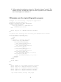

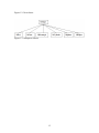


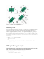


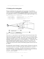
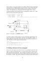


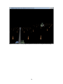

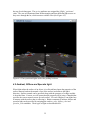
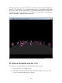


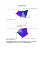


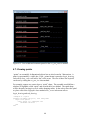
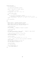
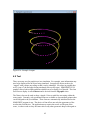

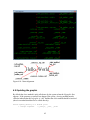
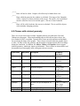


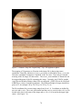


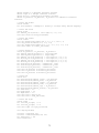


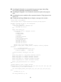


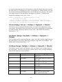


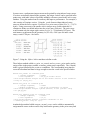


![MapInfo [v9.5 - v10.0] User manual PDF](http://vs1.manualzilla.com/store/data/005662542_1-c58f11f989f54f88b5c049879cd1b1b4-150x150.png)