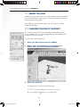
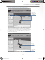
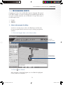
1
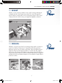
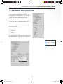
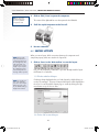
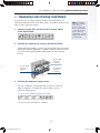
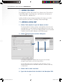
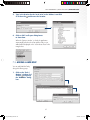
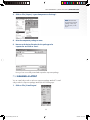
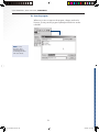
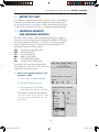
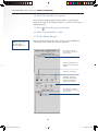
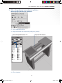
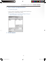
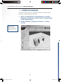
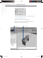
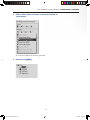
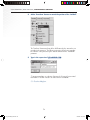
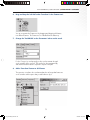
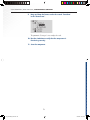
3D SIMULATION SOFTWARE
QUICK START GUIDE 3.1
3D SIMULATION SOFTWARE
QUICK START GUIDE 3.1
VISUAL COMPONENTS
QUICK START GUIDE
RELEASE 3.1
DECEMBER 15TH, 2004
[email protected]
Korppaanmäentie 17 CL6
00300 Helsinki, Finland
Tel: +358 (0)9 323 2250
Fax: +358 (0)9 323 2251
[email protected]
www.visualcomponents.com
WWW.VISUALCOMPONENTS.COM
The Visual Components logo, 3DCreate, 3DRealize and 3DVideo
are registered trademarks of Visual Components Oy, Inc., registered
in the USA, Europe and other countries. All other brand names,
product names, or trademarks belong to their respective holders.
VISUAL COMPONENTS OY. ALL RIGHTS RESERVED.
FOR SPECIFIC TUTORIALS VISIT
WWW.VISUALCOMPONENTS.COM
VISUAL COMPONENTS OY. ALL RIGHTS RESERVED.
TABLE OF CONTENTS
1. INTRODUCTION
2
1.1. WELCOME!
2
8.1. BEFORE YOU START
38
1.2. ABOUT THIS GUIDE
2
8.2. EXPORTING AN IMAGE
38
1.3. DOCUMENT CONVENTIONS
2
1.4. FINDING INFORMATION
2
2. OVERVIEW
8. EXTRACTING DATA
8.3. EXPORTING GEOMETRY
9. VIEWING AND EXPORTING STATISTICS
37
41
43
3
9.1. BEFORE YOU START
44
2.1. VISUAL COMPONENTS
4
9.2. VIEWING STATISTICS OF A COMPONENT
44
2.2. 3DVIDEO®
5
2.3. 3DREALIZE®
5
2.4. 3DCREATE®
3. ACTIVATING THE PRODUCT
45
47
6
10.1. BEFORE YOU START
48
7
10.2. CHANGING THE POSE OF THE ROBOT
48
3.1. ACTIVATION
8
3.2. SYSTEM REQUIREMENTS
8
4. NAVIGATING THE 3DWORLD
9.3. EXPORTING STATISTICS
10. USING ROBOTS
10.3. PROGRAMMING ROBOTS
9
53
11. CREATING A COMPONENT
57
11.1. BEFORE YOU START
59
4.1. BEFORE YOU START
10
4.2. VIEWING THE SCREEN LAYOUT
10
4.3. TOOLBAR NAVIGATION
11
11.3. WORKING WITH FEATURES AND BEHAVIORS
62
4.4. SHORTCUT NAVIGATION
12
11.4. WORKING WITH INTERFACES
65
13
11.5. TESTING THE CONVEYOR
5. USING LAYOUTS AND COMPONENT PACKAGES
11.2. IMPORTING GEOMETRY AND
ASSIGNING MATERIALS
68
5.1. BEFORE YOU START
14
5.2. INSTALLING A COMPONENT PACKAGE
14
12.1. BEFORE YOU START
70
5.3. NAVIGATING WITH THE ECAT TAB
17
12.2. WORKING WITH PARAMETERS
70
5.4. LOADING COMPONENTS AND LAYOUTS
18
5.5. RUNNING THE SIMULATION
19
6. CREATING AND MODIFYING LAYOUTS
12. PARAMETERIZING A COMPONENT
59
12.3. WORKING WITH GEOMETRY SETS
13. CREATING CUSTOM COMPONENT LOGICS
69
71
77
21
13.1. BEFORE YOU START
79
6.1. BEFORE YOU START
22
13.2. WORKING WITH SENSORS AND SIGNALS
79
6.2. BUILDING AN ASSEMBLY LAYOUT
22
13.3. PYTHON COMPONENT SCRIPTING
84
6.3. COPYING COMPONENTS
25
13.4. RUNNING THE SIMULATION
6.4. SAVING LAYOUTS
26
6.5. TRANSLATING AND ROTATING COMPONENTS
7. MANAGING ECATS
INDEX
85
86
27
29
7.1. BEFORE YOU START
30
7.2. ADDING A LOCAL ECAT
30
7.3. ADDING A WEB ECAT
31
7.4. CREATING AND EXPORTING A COMPONENT
PACKAGE WITH 3DREALIZE
7.5. E-MAILING A LAYOUT
32
33
7.6. CREATING A COMPONENT PACKAGE
WITH 3DCREATE
34
1
VC_QuickStart_Sivut.indd 1
04/10/06 13:36:21
VISUAL COMPONENTS | QUICK START GUIDE | INTRODUCTION
CHAPTER 1 INTRODUCTION
1.1. WELCOME!
FILE NAME
The Visual Components Quick Start Guide provides
step-by-step instructions that will enable you to learn
and use the Visual Components 3DVideo®, 3DRealize®
and 3DCreate® software products right away. The
guide also tells you where to look for more detailed
information about the many different features offered
by 3DVideo®, 3DRealize® and 3DCreate® software.
Italic typeface and blue color used to represent file
names.
MENU COMMANDS
Menu commands are described like this:
Click on ‘File | Open’. This means that you must click
on ‘File’ at the top of the application’s menubar, and
then click the ‘Open’ command in the drop-down
menu that appears.
1.2. ABOUT THIS GUIDE
The chapters in the guide are arranged to provide
information and instructions from the basics to the
more advanced use of the software. Each chapter
begins with a brief overview and a list of preparations
that you need to perform in order to fully use and
benefit from each software product. The chapters
are divided into a number of exercises, which are
subdivided into steps and procedures. Additional
information (text, notes and tips) about each of
the steps can be found below the step. Illustrations
have also been included to assist the user visually in
following the steps and procedures.
IMPORTANT TERMS
Important Terms and Names are written in italic.
NOTES & TIPS
NOTE! Notes contain
important information.
In this Quick Start Guide, clicking always refers to
the left mouse button by default. The use of the right
mouse button is always mentioned separately.
1.3. DOCUMENT CONVENTIONS
1.4. FINDING INFORMATION
The Quick Start Guide uses the following document
conventions:
You can find additional information on Visual
Components applications by referring to the following
sources:
ORDERED STEPS
1.
TIP! Tips contain helpful
advice that make using
the software easier.
Steps you must do are numbered and
in bold type.
USER MANUALS:
accessible from the Menubar’s Help menu.
PROCEDURE STEPS
ONLINE SUPPTORT:
1.1. Procedural steps are substeps that you must
perform under main steps.
www.visualcomponents.com/support
COMPUTER OUTPUT
Computer generated messages
USER INPUT
What you must type in when prompted to do so.
2
VC_QuickStart_Sivut.indd 2
04/10/06 13:36:24
CHAPTER 2
VC_QuickStart_Sivut.indd 3
OVERVIEW
04/10/06 13:36:45
VISUAL COMPONENTS | QUICK START GUIDE | OVERVIEW
2.1. VISUAL COMPONENTS
Visual Components provides tools to package complex automation systems into
reusable simulation components. Components are equipment models of real
machines that simply snap together to make new layouts. The component models
provide a solid ground for different factory and robot simulations. Components
mimic the appearance and behaviour of the “real thing” and are made up from
CAD Geometry, Behaviors, and Interfaces, as illustrated in the picture.
INTERFACE
•
•
•
•
GEOMETRY (NATIVE CAD)
•
•
•
•
Configuration rules
Material flow
Real-time connections
Signal mapping
Materials
Parameter control
Hierarchical tree model
Scaleable LOD
BEHAVIOR
•
•
•
•
Kinematics
Motion paths
Process logic
Sensors
Visual Components has a layered product family that delivers 3D simulation for
a wide user group without exposing them to unnecessary complexity. There is a
simple 3D simulation viewer called 3DVideo®, a layout creation and optimization
tool called 3DRealize®, and a component author and application development kit
called 3DCreate®.
4
VC_QuickStart_Sivut.indd 4
04/10/06 13:37:04
VISUAL COMPONENTS | QUICK START GUIDE | OVERVIEW
2.2. 3DVIDEO®
3DVideo® is a free, interactive simulation viewer used for viewing pre-built layouts
configured with other Visual Components products. The viewer is designed for
anyone with basic computer skills to view a running factory layout on their own PC
or laptop without the need for training or a high-powered graphics workstation.
2.3. 3DREALIZE®
3DRealize® is a layout proposal tool for generating working modules or production
systems from a library of components. It is targeted towards sales people and
application engineers who can analyse, demonstrate, and present different layouts,
equipment selections and throughput possibilities in real time with staff, suppliers
and customers. The discrete event simulation engine drives production flow based on
component parameters that have an effect on the material flow and processing times.
Standard routing rules and statistical analysis tools are available to analyse different
production scenarios.
5
VC_QuickStart_Sivut.indd 5
04/10/06 13:37:06
VISUAL COMPONENTS | QUICK START GUIDE | OVERVIEW
2.4. 3DCREATE®
3DCreate® is the component model and application authoring tool used to
build and publish 3D simulation components, layouts and new 3D simulation
based applications. Starting with exisiting engineering 3D CAD data, the model
geometry is optimised for display on standard computers. Easy to use Plug-andplay connection interfaces are added along with realistic behaviours to result
in a lightweight parametric based simulation model that can represent an entire
product family. Configuration rules help to control how a component may be used
and operated in a layout and what information is available for automating the
generation of a quotation. Once finished, the equipment models can be published
PRODUCT & PROCESS DATA
Specifications
Organise CAD
3D CAD Files
Documentation
Add behavior
Define layout
Check/Deliver!
to a web page for global access by any Visual Component based software
product. 3DCreate® includes all the functionality of 3DRealize® and 3DVideo®.
3DCreate is also a Software Development Kit (SDK) for 3rd party application
development. The SDK gives the possibility to interface or embed the simulation
models with other software or to create new fully featured simulation based
software applciations. In a single package the user gains access to a material
flow discrete event simulation engine, robotic kinematic modelling services,
a synchronized scene graph and a flexible licensing mechanism. Python scripting
and Microsoft COM interfaces provide flexibility to extend the product family to
meet specific developer needs.
6
VC_QuickStart_Sivut.indd 6
04/10/06 13:37:08
CHAPTER 3
VC_QuickStart_Sivut.indd 7
ACTIVATING THE PRODUCT
04/10/06 13:37:26
VISUAL COMPONENTS | QUICK START GUIDE | ACTIVATING THE PRODUCT
3.1. ACTIVATION
NOTE! Activation is
described in more detail in
Setting up | Activation in
the User’s Guide.
You can activate your Visual Components product by obtaining a valid Product Key
from Visual Components or an authorised reseller. A Product Key is delivered upon
purchase. You can evaluate the product by obtaining an evaluation key that will
work for 7 days by visiting www.visualcomponents.com/evaluate
When the program starts you will be prompted to provide the Product Key.
The program will try to automatically activate the software by connecting to
the Visual Components license server. If automatic activation fails (often due to
restrictive firewall settings), then you need to retrieve the license key manually
by visiting Visual Components at: www.visualcomponents.com/licensor
Activation
welcome screen
Enter
the product key
NO
Enter contact
information
Internet
connection
YES
NO
Automatic activation
succeeds
YES
Start
application
NO
YES
Enter:
• product key
• computer identity
• licence key
Manual
activation
succeeds
NO
3.2. SYSTEM REQUIREMENTS
NOTE! For further
information, refer to
Setting up | Requirements
in the User’s Guide.
In order to install and optimally use Visual Components 3DVideo®, 3DRealize® and
3DCreate®, you need the following minimum hardware configurations:
3DVIDEO®
•
•
•
Pentium II, 350 MHz
RAM 128 MB
OpenGL compatible graphics with 800 x 600 resolution and
16-bit color depth
3DREALIZE®
•
•
•
Pentium II, 350 MHz
RAM 128 MB
OpenGL compatible graphics with 800 x 600 resolution and
16-bit color depth
3DCREATE®
•
•
•
Pentium III, 600 MHz
RAM 128 MB
OpenGL compatible graphics with 1024 x 768 resolution and
16-bit color depth
8
VC_QuickStart_Sivut.indd 8
04/10/06 13:37:44
CHAPTER 4
VC_QuickStart_Sivut.indd 9
NAVIGATING THE 3DWORLD
04/10/06 13:38:00
VISUAL COMPONENTS | QUICK START GUIDE | NAVIGATING THE 3DWORLD
4.1. BEFORE YOU START
There are no prerequisites for this chapter.
4.2. VIEWING THE SCREEN LAYOUT
This section contains important information that you be familiar with before using
the product. The Screen layout contains tools, options, controls and messages that
help you work with components and layouts in the 3DWorld.
Menubar
Main toolbar
3DWorld
Simulation controls
Selection Filter toolbar
Tabbed Panel
Message panel
Status bar
TIP! If you forget what
a button does, just
position the cursor over
the button to display
a brief explanation.
3DWORLD
Full three-dimensional
display area.
MESSAGE PANEL
Displays important messages.
STATUS BAR
Displays the selection mode
and the name of the selected
object. It also has different
toggle option buttons.
MENUBAR
Allows you to access the
functionality of 3DCreate®.
MAIN TOOLBAR
Displays the most frequently
used commands.
TABBED PANEL
Allows the selection of
different contexts.
SIMULATION CONTROLS
Controls the simulation and has
commands similar to a standard
CD player.
DYNAMIC TOOLBAR
Displays possible options
available with the current
command.
CONTEXT-SENSITIVE
MENU
Activated by using the right
mouse button to access
commands available in the
current context.
SELECTION FILTER
TOOLBAR
Controls the current
selection type.
10
VC_QuickStart_Sivut.indd 10
04/10/06 13:38:18
VISUAL COMPONENTS | QUICK START GUIDE | NAVIGATING THE 3DWORLD
4.3. TOOLBAR NAVIGATION
You can easily navigate in the 3DWorld with toolbar buttons and shortcut keys.
When you navigate with the toolbar buttons, the navigational command stays
active until you select another command or end the navigation by pressing the
space bar on your keyboard. To navigate with the toolbar buttons do the following:
ORBITING
Click on the ‘Orbit’ button and move the mouse while pressing the left mouse button
in the 3DWorld. This orbits the viewpoint. This command orbits the viewpoint
around a center of interest defined in the middle of the 3DWorld. The center of
interest can be changed by panning the model to a new position on the screen or
centering the model to a specific part of a component.
TIP! To change the center
of interest, press Shift
and at the same time click
on a new part to be the
center of interest in the
3DWorld. You must click
on a part.
PANNING
Click on the ‘Pan’ button and move the mouse with the left mouse button pressed
over the 3DWorld to pan the camera. The Pan button moves the viewpoint along
a view plane parallel to the screen.
ZOOMING
Click on the ‘Zoom’ button and move the mouse up and down with the left
mouse button pressed over the 3DWorld to zoom in and out. Zooming moves
the viewpoint closer or further away from the center of interest. As with the Orbit
function, to change the center of interest, press the Shift key and at the same time
click on a part to be the new center of interest in the 3DWorld.
FILLING
TIP! Filling is always
useful if the 3DWorld
view is empty when there
is a model loaded.
Click on the ‘Fill’ button to fill the 3DWorld.
LAYOUT FILLING
Fill places the complete model within view in the 3DWorld.
11
VC_QuickStart_Sivut.indd 11
04/10/06 13:38:20
VISUAL COMPONENTS | QUICK START GUIDE | NAVIGATING THE 3DWORLD
4.4. SHORTCUT NAVIGATION
Using the shortcut keys is a quick and simple way to navigate in the 3DWorld.
However, you must remember that when you navigate with the shortcut keys, the
navigational command is executed on top of the previous command. This means
that when you end the navigation, the previous command becomes active again.
TO ORBIT
Press ‘Ctrl’ + Hold down the left mouse button and drag.
TO PAN
Press ‘Alt’ + Hold down the left mouse button and drag.
TO ZOOM
Press ‘Shift’ + Hold down the left mouse button and drag.
TO FILL
Press ‘Shift, Ctrl and F’ keys at the same time.
12
VC_QuickStart_Sivut.indd 12
04/10/06 13:38:22
CHAPTER 5
VC_QuickStart_Sivut.indd 13
USING LAYOUTS AND
COMPONENT PACKAGES
04/10/06 13:38:37
VISUAL COMPONENTS | QUICK START GUIDE | USING LAYOUTS AND COMPONENT PACKAGES
5.1. BEFORE YOU START
In order to complete this chapter, you need to install ‘Demo Components’.
The ‘Package file’ is called DemoPackage_31.vcp , and you can find and
download it to your hard drive from the product installation CD or from Visual
Components online support at: www.visualcomponents.com
5.2. INSTALLING A COMPONENT PACKAGE
You can install a component package by using one of the following three methods:
•
•
•
Double-click on the ‘Package file’ in the File manager.
Drag-and-drop the ‘Package file’ from the File manager to the 3DWorld.
Open the file using ‘File | Open’.
1.
Double-click on the ‘Package file’ in File explorer.
NOTE! If you have
more than one Visual
Components applications
installed a pop-up menu like
the one on right appears:
With what application
do you want the package
to be opened with?
Specify the application
by selecting for example
3DRealize®. If you have
only one valid application
installed the pop-up menu
does not appear.
1.1 Click on ‘Install’ to install the components.
The following window appears and shows the contents of a typical component
package. If you have already installed any of the components that this package
contains, they are unselected by default.
14
VC_QuickStart_Sivut.indd 14
04/10/06 13:38:55
VISUAL COMPONENTS | QUICK START GUIDE | USING LAYOUTS AND COMPONENT PACKAGES
Name of
a component or layout.
File location relative
to the eCat root.
Revision of
a component or layout.
Component’s
status.
Select whether
the component
or layout will be
installed
Target eCat,
Default option
works for most
cases
Component in the package is the same as what the user has:
Component in the package doesn’t exist in the user’s package:
Component in the package is newer than what the user has:
Component in the package is older than what the user has:
The installation time depends on the speed of your computer. Please refer to
the Requirements in the User’s Manual.
The following pop-up Message window means that you have successfully
installed the component package and shows all the installation details.
1.2 Click on ‘OK’ to close the Message window.
15
VC_QuickStart_Sivut.indd 15
04/10/06 13:38:57
VISUAL COMPONENTS | QUICK START GUIDE | USING LAYOUTS AND COMPONENT PACKAGES
2.
Drag-and-drop the ‘Package file’ into the 3DWindow.
3.
Click on ‘File | Open’ to install the ‘Package file’.
NOTE! Remember to
set the file type to .vcp
so that you can see the
package files when you
browse the directories.
16
VC_QuickStart_Sivut.indd 16
04/10/06 13:38:58
VISUAL COMPONENTS | QUICK START GUIDE | USING LAYOUTS AND COMPONENT PACKAGES
5.3. NAVIGATING WITH THE ECAT TAB
Electronic Catalogs navigating (eCats) give access
to the components and the layouts located on a
local hard drive or on the Internet. The ‘eCat’ tab
works like a standard Windows tree browser.
By default there are three local eCats – ‘Local
Components’, ‘My Components’ and ‘My Layouts’
– and one web eCat – ‘Web Resources’.
There are four options to show components and
layouts in the eCat:
•
•
•
•
Large icons
Small icons
List icons
Details.
You can change these options from the pop-up menu
that appears when you click with your right mouse
button over the ‘eCat’ tab.
TIP! You can refresh
the eCat tree browser with
the F5 key.
17
VC_QuickStart_Sivut.indd 17
04/10/06 13:39:00
VISUAL COMPONENTS | QUICK START GUIDE | USING LAYOUTS AND COMPONENT PACKAGES
5.4. LOADING COMPONENTS AND LAYOUTS
NOTE! Double-clicking on
or dragging the file from
the eCat does not apply
to 3DVideo®, since it does
not have the eCat tab.
You can load components and layouts into the 3DWorld with the following
methods:
•
•
•
•
Double-click on the file in the File explorer
Drag-and-drop the file from the File manager to the 3DWorld
Open the file using ‘File | Open’
Double-click on or drag the file from the eCat.
However, the most convenient way to load components and layouts is to use
the eCat by following the steps below:
1.
Double-click on ‘Local components | Demo Layouts’ and dragand-drop the ‘Assembly Automation’ layout into the 3DWorld.
When you double-click on a component or a layout in the eCat, it performs
the same function as drag-and-drop. Double-clicking places the component
or the layout in the middle of the floor, while drag-and-drop places the
component or the layout exactly where you dropped it in the 3DWorld.
18
VC_QuickStart_Sivut.indd 18
04/10/06 13:39:01
VISUAL COMPONENTS | QUICK START GUIDE | USING LAYOUTS AND COMPONENT PACKAGES
5.5. RUNNING THE SIMULATION
Simulation adds the 4th dimension to the 3DWorld - time. This is implemented in
Visual Components by using a discrete event approach in which the simulation
time advances in discrete (non-linear) steps defined by “physical” events triggered
in the behaviors of the component models. The implementation is not the same as
animation, where the movement between time intervals is manually defined and
fixed.
Once you have loaded the ‘Assembly Automation’ layout into the 3DWorld, you
can run the simulation by following the steps below:
1.
Click on the ‘Run/Stop’ button to start the simulation.
TIP! The simulation
can be paused with
the ‘Run/Stop’ button.
This will not reset the
simulation.
The Assembly Automation component layout is now in operation.
2.
Drag the ‘Simulation Speed’ slider forwards or backwards
to adjust the simulation speed.
19
VC_QuickStart_Sivut.indd 19
04/10/06 13:39:03
VISUAL COMPONENTS | QUICK START GUIDE | USING LAYOUTS AND COMPONENT PACKAGES
If you move the mouse over the ‘Clock’, you see what the current time scale
the ‘Clock’ is using . By default the ‘Clock’ shows hours, minutes and seconds.
3.
Click on ‘Tools | Options’ and select the ‘Simulation tab’
to change the ‘Clock’ settings.
There are five different time scales for you to choose from:
•
•
•
•
•
Minutes : Seconds : Milliseconds
Hours : Minutes : Seconds.
Days : Hours : Minutes
Months : Days : Hours
Years : Months : Days
4.
Choose a scale and click on ‘OK’ to close the window.
5.
Click on the ‘Reset’ button to reset the simulation.
When you reset the simulation, the ‘Clock’ starts from zero when you
next start the simulation.
20
VC_QuickStart_Sivut.indd 20
04/10/06 13:39:04
CHAPTER 6
VC_QuickStart_Sivut.indd 21
CREATING AND
MODIFYING LAYOUTS
04/10/06 13:39:35
VISUAL COMPONENTS | QUICK START GUIDE | CREATING AND MODIFYING LAYOUTS
6.1. BEFORE YOU START
A layout is an arrangement of interconnected components that collectively model
and simulate an automation line or robot cell. The components used in Visual
Components layouts have been designed to hide as much simulation complexity as
possible so that creating and modifying layouts does not require special expertise.
In this chapter you need the ‘Demo Components’ (see Section 5.2 Installing
a component package).
6.2. BUILDING AN ASSEMBLY LAYOUT
In this section you build and operate the ‘Assembly Automation’ layout that was
retrieved and used in the previous example. The components are numbered to
indicate the order in which the layout can be assembled.
1.
Click on ‘eCat | Local Components | Demo Components |
Assembly Automation’ and retrieve the ‘High Speed Cell’
2.
Retrieve the ‘Pallet Conveyor’.
3.
Click on the ‘Param’ tab and change the PalletWidth to 200 mm.
Make sure the Pallet Conveyor is selected.
In the the ‘Param’ tab you can control all the visible properties of a component.
ABOUT PROPERTIES
The properties control the appearance and the behavior of a component. Every
component has two basic properties: Name and Material. Name defines the name of
the component and Material defines the “color” of a component. Material can only
be applied to those geometries inside the component that do not have a predefined
material assigned by the Component modeler.
Most components also have additional, User-defined properties. User-defined properties
typically change the appearance of a component, such as the width of a conveyor
as in this case. User-defined parameters are located either on the ‘General’ subtab or
on an ‘Additional’ subtab, depending on how the Component modeler defined them.
Behaviors of a component introduce properties as well. Behavior properties modify the
way components work and are displayed in their own subtab, which corresponds to the
name of the behavior.
22
VC_QuickStart_Sivut.indd 22
04/10/06 13:39:54
VISUAL COMPONENTS | QUICK START GUIDE | CREATING AND MODIFYING LAYOUTS
4.
Click on the ‘PnP’ button from the ‘Main toolbar’ and move the
‘Pallet Conveyor’ inside the ‘High Speed Cell’ until it snaps into
place.
Plug-and-Play (PnP) is used for connecting components to each other and is
automatically activated after a component is retrieved from the eCat.
INTERFACE
ABOUT INTERFACES
Communication between components is implemented through a common interface.
An interface can be thought of as an electrical cable with a plug at each end. The cable
transfers specific information between the components through the pins in the plug.
FLOW FIELD
SIGNAL FIELD
The pins represent information fields in the Interface used for specific information flows.
There can be an infinite number of interface fields and connections will only occur
between two components matching fields. An interface can deliver many types of
information such as:
•
•
•
•
Material flow
Communication signals (digital/analog/messages)
Task publishing
Physical attachment information.
When you activate the PnP command and move a component toward another
component, the system detects if there are matching interfaces within in
close proximity. When a match is found, a guide line appears and as you
move closer in the direction of the guide line, the component will snap to its
connection point.
As the image below shows, the yellow arrows indicate unconnected interfaces
while green arrows indicate connected interfaces. The green guide line guides
you to the correct interface connection location.
The interface indicator
becomes green when
the interface is connected.
When the interface
is not connected,
the indicator is yellow.
23
VC_QuickStart_Sivut.indd 23
04/10/06 13:39:56
VISUAL COMPONENTS | QUICK START GUIDE | CREATING AND MODIFYING LAYOUTS
5.
Retrieve the ‘Robot Cartesian’ and ‘PnP’ it to the ‘High Speed Cell’.
6.
Retrieve the ‘Card Feeder’ and ‘PnP’ it to the ‘High Speed Cell’.
7.
Retrieve the ‘Generic Feeder’ and ‘PnP’ it to the ‘Pallet Conveyor’.
8.
Run the simulation.
The assembly line is now ready for simulation. Press the simulation Start button
to see the line in action. See Section 5.5 Running the simulation.
24
VC_QuickStart_Sivut.indd 24
04/10/06 13:39:58
VISUAL COMPONENTS | QUICK START GUIDE | CREATING AND MODIFYING LAYOUTS
6.3. COPYING COMPONENTS
You can use the Cut, Copy and Paste commands as you would in any other desktop
application. Using these commands is a very good way to build efficient running
layouts. Copied components share memory data resulting more efficient computer
processing, and this can be noticeable on lower performance computers or very large
models. To copy a component perform the following steps:
1.
Click on the ‘High Speed Cell’ to select it.
2.
Click on ‘Edit | Copy’ to copy the component.
Now the component has been copied to the clipboard.
TIP! You can use the
Context-sensitive pop-up
menu to copy the
component by clicking
the right mouse button
over the component. The
content of the pop-up
menu changes depending
on what kind of object
you have selected.
25
VC_QuickStart_Sivut.indd 25
04/10/06 13:40:00
VISUAL COMPONENTS | QUICK START GUIDE | CREATING AND MODIFYING LAYOUTS
TIP! You can use the
Context-sensitive popup menu to paste the
component as well.
3.
Click on ‘Edit | Paste’ to paste the component.
The content of the clipboard has now been pasted to the 3DWorld.
4.
‘PnP’ the copied component to the first cell.
5.
Run the simulation.
6.4. SAVING LAYOUTS
NOTE! The layout file
only saves references to
component geometry, not
the actual geometry. Also
if the components of a
layout file are not stored
locally on your computer
the complete layout will
not be loaded, and error
messages will be reported.
When you save a layout, all the connections between the components and
component property values are saved in the ‘Layout file’.
1.
Click on ‘Save’ on the ‘Main toolbar’ to save the layout.
First, you are prompted for a filename. If you have already saved the layout
the filename is not asked for.
1.1. Fill in the credits for the layout.
NOTE! You can also use
‘File | Save’ and ‘File |
Save As’ to save a layout.
When using ‘File | Save
As’, the filename dialog is
displayed as a default.
Credits are always displayed when you load a layout by double-clicking on
it in the ‘File manager’. The project name and description will be displayed in
the eCat. You can also add a company logo to credits by clicking the right
mouse button on top of the icon area.
1.2. Click on ‘OK’ to save the layout.
26
VC_QuickStart_Sivut.indd 26
04/10/06 13:40:02
VISUAL COMPONENTS | QUICK START GUIDE | CREATING AND MODIFYING LAYOUTS
6.5. TRANSLATING AND ROTATING COMPONENTS
If you need to move or re-align components without connecting them use the
‘Translate’ and ‘Rotate’ buttons on the ‘Main toolbar’. These buttons are active only
when you have components selected.
1.
Select the second ‘Cell’ and click on the ‘Translate’ button
on the ‘Main toolbar’
2.
Translate the component by using the directional handles
NOTE! The Translation
and Rotation commands
do not connect or
disconnect components.
However, if you translate
a connected component
too far away from its
counterpart the component
will be disconnected once
you activate ‘PnP’.
Using the directional handles is a common way to manipulate objects interactively
with Visual Components applications. To translate or rotate the component, move
your mouse over the desired handle and drag it with your left mouse button
pressed.
The blue handle
corresponds
to z-direction.
The green handle
corresponds to
y-direction.
3.
The red handle
corresponds
to x-direction.
Translate the component along a Vector.
The ‘Vector Translation’ command will ask for two points to pick that
define the translation. To translate the component along a vector,
perform the following steps:
3.1. Click on the ‘Translate along a Vector’ button.
3.2. Pick two points that define the translation.
27
VC_QuickStart_Sivut.indd 27
04/10/06 13:40:04
VISUAL COMPONENTS | QUICK START GUIDE | CREATING AND MODIFYING LAYOUTS
NOTE! The interactive
commands deliver
instructions to the
‘Message Panel’. To clear
or save the messages click
the right mouse button
over the ‘Message Panel’.
Debug messages provide
additional information
about the operations
being executed.
The ‘Snap Filler’ dialog will assist you in choosing points and surfaces
in the 3DWorld.
4.
Enter new coordinates for the component origin.
You can enter the exact coordinate values to define the translation.
28
VC_QuickStart_Sivut.indd 28
04/10/06 13:40:06
CHAPTER 7
VC_QuickStart_Sivut.indd 29
MANAGING ECATS
04/10/06 13:40:22
VISUAL COMPONENTS | QUICK START GUIDE | MANAGING ECATS
7.1. BEFORE YOU START
The configuration of eCats is done with the ‘Tools | Options’ menu. There are three
local eCats by default – ‘Local Components’, ‘My Components’ and ‘My Layouts’
– and one web eCat – ‘Web Resources’.
In order to be able to export a component package in this chapter, you need the
‘Demo Components’ (see Section 5.2 Installing a component package).
7.2. ADDING A LOCAL ECAT
1.
Click on ‘Tools | Options’ to open the ‘Options window’.
The ‘General’ tab in the ‘Options window’ contains definitions for both ‘Local’
and ‘Web eCats’. You can modify the eCats by modifying the text in the ‘Local’
and ‘Web eCat’ fields, or you can use the dialog box button next to the text field.
To add a ‘Local eCat’ with the dialog box, do the following steps:
2.
Click on
to open up the ‘Local eCat’ dialog box.
Description of
eCat.
Location of
eCat.
This dialog box displays the defined eCats. Every item on the list has a
description and a location on a local or network drive.
If you should need to remove or change the order of the eCats, you can
select the desired eCat in the ‘eCat editor’ and click on: ‘Remove’, ‘Move Up’
or ’Move Down’.
3.
Click on ‘Add’ to add a ‘Local eCat’.
4.
Type in the description for the ‘Local eCat’ in the ‘Description’ field.
30
VC_QuickStart_Sivut.indd 30
04/10/06 13:40:39
VISUAL COMPONENTS | QUICK START GUIDE | MANAGING ECATS
5.
Type in the location for the ‘Local eCat’ in the ‘Address’ text field
or click on the
and browse the location.
6.
Click on ‘OK’ in all open dialog boxes
to close them.
When the ‘Options window’ is closed, the application
automatically refreshes the eCats and the eCat you just
added will be displayed on the ‘eCat’ tab as shown in the
image below:
7.3. ADDING A WEB ECAT
You can add a Web eCat by
doing the following steps:
1.
Click on the ‘Tools |
Options’ window and
click on
to open up
the ‘Web eCat’ dialog
box.
31
VC_QuickStart_Sivut.indd 31
04/10/06 13:40:42
VISUAL COMPONENTS | QUICK START GUIDE | MANAGING ECATS
2.
Type in the description for the ‘Web eCat’ in the ‘Description’
text field.
3.
Type in the Internet address in the ‘Address’ text field.
NOTE! It is not possible to
add the Internet address
by browsing. The Internet
address above is the same
as the ‘Web Resources’
eCat has.
For example, you can type in the following Internet address:
http://download.visualcomponents.net/eCat/VisualComponents/3.1/
index.htm.
4.
Click on ‘OK’ in all windows to close the dialog boxes.
ABOUT WEB ECATS
Web eCats are standard HTML pages that contain links to component files on the server.
To create a ‘Web eCat’, you need to upload the Component files to your server as well
as generate the web pages. Furthermore, your ‘Web eCat’ root must have a special
eCat.map file that contains information about the locations of components on the web.
For more information about creating eCats, see Basic Tasks for Constructing a Layout in
the User’s Guide.
7.4. CREATING AND EXPORTING A COMPONENT
PACKAGE WITH 3DREALIZE®
The layouts do not contain the actual components (only references to them). When
you send a layout, you must ensure that that the recipient has all the components
your layout refers to in his eCat. You can send the layout excluding components
by creating a component package with 3DRealize® or 3DCreate®. . For more
information on the installation of component packages, see Section 5.2 Installing
a component package.
To create and export a component package with 3DRealize®, do the following
steps:
1.
Make sure the 3DWorld is clear of objects by creating
a new layout. Click on ‘New’ on the ‘Main toolbar’.
2.
Click on ‘eCat | Local Components | Demo Layouts’ and retrieve
the ‘Material Handling’ layout.
32
VC_QuickStart_Sivut.indd 32
04/10/06 13:40:43
VISUAL COMPONENTS | QUICK START GUIDE | MANAGING ECATS
3.
Click on ‘File | Export | Layout Components as Package’.
NOTE! Remember that
the generated component
package contains only
the components, not the
layout.
4.
Give the component package a name.
5.
Browse to the desired location for the package to be
exported to and click on ‘Save’.
Now you have successfully created and exported a component package.
7.5. E-MAILING A LAYOUT
You can e-mail a layout with or without a component package attached. To e-mail
a layout with the component package attached, do the following steps:
1.
Click on ‘File | E-mail Layout’.
33
VC_QuickStart_Sivut.indd 33
04/10/06 13:40:46
VISUAL COMPONENTS | QUICK START GUIDE | MANAGING ECATS
2.
Click on ‘Yes’ to attach the component package to the E-mail
when prompted.
3.
Fill in the credits and click on ‘OK’.
The default E-mail application is opened with the layout and component
package attachments.
7.6. CREATING A COMPONENT PACKAGE
WITH 3DCREATE®
Creating a component package with 3DCreate® is the same as with 3DRealize®
except that you can browse and pick the individual components and layouts you
want to include in your package. To create a component package with 3DCreate®,
do the following steps:
1.
Click on ‘Tools | Create Component Package’.
34
VC_QuickStart_Sivut.indd 34
04/10/06 13:40:47
VISUAL COMPONENTS | QUICK START GUIDE | MANAGING ECATS
2.
Select the location for the component package.
3.
Select which layouts and components you want to include in
the package from the ‘Package dialog box’.
Select the location
for the package
Select the directories
or individual files to
be included
The size of the package
The number of components and
layouts in the package.
The dialog box displays all the ‘Local eCats’ from which you can choose
the directories or individual files to include.
4.
Click on ‘Create’ to create the package.
35
VC_QuickStart_Sivut.indd 35
04/10/06 13:40:48
VISUAL COMPONENTS | QUICK START GUIDE | MANAGING ECATS
36
VC_QuickStart_Sivut.indd 36
04/10/06 13:40:50
CHAPTER 8
VC_QuickStart_Sivut.indd 37
EXTRACTING DATA
04/10/06 13:41:05
VISUAL COMPONENTS | QUICK START GUIDE | EXTRACTING DATA
8.1. BEFORE YOU START
In order for you to extract data in this chapter, you will need the ‘Demo
Components’ (see Section 5.2 Installing a component package).
8.2. EXPORTING AN IMAGE
You can customize and export your images from the 3DWorld to external files by
doing the following steps:
1.
Click on ‘View | Settings | 3DWorld’ and select the desired
background color for the image.
Display or hide
the gridfloor
TIP! To speed up the
graphics performance
on a slow computer try
disabling textures and
transparencies. Make sure
that geometry optimization
is on. In addition, you can
try setting the display
threshold to 5 or 10
pixels.
Select the
background color.
1.1. Click on ‘OK’.
2.
Click on the ‘eCat | Local Components | Demo Layouts’ and
retrieve the ‘Assembly Automation’ layout.
38
VC_QuickStart_Sivut.indd 38
04/10/06 13:41:23
VISUAL COMPONENTS | QUICK START GUIDE | EXTRACTING DATA
3.
Click on ‘View | Rotate Light’ to adjust the light.
You can adjust the intensity and direction of light by moving the slider to
darken or to lighten the 3DWorld. To control the direction of light drag
the red, green or blue circles in the handle.
Adjust the intensity
of the light.
Adjust the direction of
the light by dragging
the handle.
You can always reset the light settings to their original settings
by clicking-on ‘Reset’.
3.1. Click on ‘Done’ when you have the desired light settings.
4.
Choose a viewpoint for the image.
Navigate the 3DWorld until you have the ideal view you want for your image.
The image will be exported from the current 3DWorld viewpoint.
5.
Click on ‘File | Export | Screen Bitmap’ to generate the image.
5.1. Select a ‘File format’ and
click on ‘Save’ to save the file.
The image will be generated
using the screen resolution
which means that it is as big as
your 3DWorld window.
39
VC_QuickStart_Sivut.indd 39
04/10/06 13:41:24
VISUAL COMPONENTS | QUICK START GUIDE | EXTRACTING DATA
Follow the next series of steps to produce a high-resolution image:
6.
Click on ‘File | Export | Bitmap’ to generate
a high-resolution image.
You will be prompted to enter the size of the image in pixels.
It is possible to enter any size, but a larger image size corresponds to a larger
file size. The image size is scaled to the screen proportion. If the image size
differs significantly from the screen’s proportion some cropping may occur.
6.1. Click on ‘OK’ to save the image.
The final image should look similar to the one below:
ABOUT IMAGE SIZES
If you need to generate images for the printer you most likely would like to have the
image resolution in dpi and image size in milimeters instead of pixels. The most typical
size conversions have been calculated for you in the table below:
Image size
For web 72 dpi
For offset printing 300 dpi
100 mm x 71 mm
280 x 200 pixels
1184 x 840 pixels
A5 (210 mm x 148 mm)
592 x 416 pixels
2480 x 1752 pixels
A4 (297 mm x 210 mm)
840 x 592 pixels
3504 x 2480 pixels
NOTE! Size in pixels = dpi x size in centimeters / 2.54
40
VC_QuickStart_Sivut.indd 40
04/10/06 13:41:26
VISUAL COMPONENTS | QUICK START GUIDE | EXTRACTING DATA
8.3. EXPORTING GEOMETRY
Geometry can be exported to an external file to generate photo-realistic images
and to do advanced dimensioning. When you export geometry, it always applies
to the entire layout. In this section, you will use the same layout as in the previous
example.
To export geometry do the following steps:
1.
Click on ‘File | Export | Layout Geometry’.
2.
Select a ‘File format’ and a ‘location’.
NOTE! 3DStudio file
format is preferred for
visualization purposes
because it preserves
material definitions.
However, 3DStudio file
format does not support
lines. For more information
on supported file formats,
refer to Supported File
Formats in the Reference
Guide.
3.
Click on ‘Save’.
41
VC_QuickStart_Sivut.indd 41
04/10/06 13:41:44
VISUAL COMPONENTS | QUICK START GUIDE | EXTRACTING DATA
42
VC_QuickStart_Sivut.indd 42
04/10/06 13:41:46
CHAPTER 9
VC_QuickStart_Sivut.indd 43
VIEWING AND EXPORTING
STATISTICS
04/10/06 13:42:01
VISUAL COMPONENTS | QUICK START GUIDE | VIEWING AND EXPORTING STATISTICS
9.1. BEFORE YOU START
NOTE! Statistics viewing
is not available for the
components that do not
support statistics.
Viewing and exporting statistics allows you to analyze and determine optimal
component layout configurations for production. The Component modeler defines
the statistical states of components in 3DCreate®, while 3DRealize® allows you
to view statistical results as you run the simulation. As a result, conflicts can be
identified and resolved early on, cycle times for specific component activities can
be measured exactly, and the results of the project can be summarized in a report.
In this chapter you will need the ‘Demo Components’ (see Section 5.2 Installing
a component package).
9.2. VIEWING STATISTICS OF A COMPONENT
You can view statistics in 3DRealize® or 3DCreate®. The statistics can also be
exported to a file for viewing and post-processing the results in an external
application.
To view statistics perform the following steps:
1.
Click on ‘eCat | Local Components | Demo Layouts’ and retrieve
the ‘Material Handling’ layout.
2.
Click on the ‘Run/Stop’ button to run the simulation.
3.
Select a ‘component’ and click on ‘Add-ons | Show Statistics’
to activate the statistics display.
The statistics display is component dependent so you need to select a component
in order to view the statistics. The ‘Turn unit’ is a good example for this purpose
since it allows you to view the full range of statistics available.
ABOUT STATISTICS
The statistics display contains three tabs that show the accumulated statistics of
a component.
The Component modeler can define an infinite number of states for a component.
All the states defined by the modeler map to the predefined system states. The ‘System
States’ tab shows how much time the component has spent in different system states in
percentages. The ‘States’ tab displays correspondingly how much time the component
has spent in a user-defined state. For instance, this turn unit has been 86.466% of its
time in busy state. To be more exact it has been busy because of the ‘Servo’ (14.58%)
and the ‘Conveyor’ (71.886%) as the ‘States’ tab displays. The ‘Component Flow’ tab
shows the accumulated statistics of the material flow. Some components like conveyors
do not have state based statistics instead they contain only flow statistics.
44
VC_QuickStart_Sivut.indd 44
04/10/06 13:42:19
VISUAL COMPONENTS | QUICK START GUIDE | VIEWING AND EXPORTING STATISTICS
9.3. EXPORTING STATISTICS
The Statistics display shows the statistics of one component. If you want to display
and post-process the statistics of a whole layout the data must be exported to an
external file. The file can be opened in an external application such as Microsoft
Excel. To export statistics do the steps below:
1.
Run the simulation.
2.
Click on ‘Add-ons | Export Statistics’ to export statistics.
3.
Write the filename and click on ‘Save’.
45
VC_QuickStart_Sivut.indd 45
04/10/06 13:42:21
VISUAL COMPONENTS | QUICK START GUIDE | VIEWING AND EXPORTING STATISTICS
The ‘Save’ command generates a .csv file that contains the statistics of all
the components in the layout. The contents of the file are displayed in the
following table:
NOTE! Python always
uses dots for decimal
numbers independently
of your windows settings.
You may need to replace
the dots with commas
depending on your
localization settings.
The exportation of the statistics is done as a ‘Python Add-on’ command. It is
also possible for you to customize or generate a new command to meet your
specific needs. For more information, see Designing Components in the User’s
Guide.
46
VC_QuickStart_Sivut.indd 46
04/10/06 13:42:22
CHAPTER 10 USING ROBOTS
VC_QuickStart_Sivut.indd 47
04/10/06 13:42:38
VISUAL COMPONENTS | QUICK START GUIDE | USING ROBOTS
10.1. BEFORE YOU START
In 3DCreate® you can teach robots to move and accomplish tasks in the 3DWorld.
Once your robot behaves as expected you can save the point-to-point sequence of
behavior statements as programs.
In this chapter you need the ‘Demo Components’ (see Section 5.2 Installing
a component package).
10.2. CHANGING THE POSE OF THE ROBOT
The ‘Teach’ tab contains the tools for manipulating and programming robots.
You can change the pose of a robot by jogging the joints or by translating and
rotating the TCP (Tool Center Point).
To jog the robot do the following steps:
1.
Click on the ‘New’ button to clear the 3DWorld.
2.
Click on ‘eCat | Local Components | DemoComponents |
Robotics Cell’ and retrieve the ‘Robot Articulated’.
3.
Click on the ‘Teach’ tab.
To change the pose of a robot do the following steps:
3.1. Click on ‘Jog Joints’ and place your cursor over the robot.
The cursor changes into
when it is over a robot node.
48
VC_QuickStart_Sivut.indd 48
04/10/06 13:42:56
VISUAL COMPONENTS | QUICK START GUIDE | USING ROBOTS
3.2. Click on and hold the “robot node” while moving your mouse.
Jog the robot by
dragging the nodes
in the 3DWorld.
The robot has joint limits defined by the Component modeler. By default you
cannot jog the joints over the limits. However, if you deactivate the limit check
it is possible to jog the joints over the limits. When you jog a joint over its
limits the whole node turns red.
The joint is
out of limits.
Toggle the limit
check here.
49
VC_QuickStart_Sivut.indd 49
04/10/06 13:42:58
VISUAL COMPONENTS | QUICK START GUIDE | USING ROBOTS
4.
Select ‘Trn tool’ to activate the translation handles for the TCP.
You can change the pose of a robot by translating the TCP. 3DCreate®
uses inverse kinematics to calculate the reflective joint values of the robot.
The TCP is manipulated by using the handles. The handles work similarly
to regular translation handles that are described in Section 6.5 Translating
and rotating components.
Translate the TCP by dragging
the handles.
5.
Click on the ‘Rot tool’ to activate the rotation handles for the TCP.
50
VC_QuickStart_Sivut.indd 50
04/10/06 13:42:59
VISUAL COMPONENTS | QUICK START GUIDE | USING ROBOTS
5.1. Click on the ‘Rotation handles’ to change the robot’s pose.
Rotate the TCP by
dragging the handles.
6.
Click on the ‘Tool’ pull-down menu to change the tool settings.
The number of TCPs in the ‘Tool’ pull-down menu is defined by the Component
modeler and varies between robots.
In some cases grippers and other components that you ‘PnP’ to the robot flange
have TCP definitions. Such components can export their TCPs to the robot
allowing you to use the exported TCPs as well.
51
VC_QuickStart_Sivut.indd 51
04/10/06 13:43:01
VISUAL COMPONENTS | QUICK START GUIDE | USING ROBOTS
7.
Click on the ‘Base’ pull-down menu to change the Base settings.
A Base is the coordinate system that the robot positions are relative to.
When you move the ‘Base’ all positions using the ‘Base’ also move. You can
select the ‘Base’ for the current point from the ‘Base’ pull-down menu.
8.
Click on the ‘Configuration’ pull-down menu to change
the configuration.
A configuration is an alternative way to reach the same position.
Configuration settings are only used with point-to-point motion. With linear
motion interpolation the closest configuration is selected automatically.
NOTE! The number of
configurations depends
on the robot.
52
VC_QuickStart_Sivut.indd 52
04/10/06 13:43:02
VISUAL COMPONENTS | QUICK START GUIDE | USING ROBOTS
10.3. PROGRAMMING ROBOTS
Programming of robots is done with RSL (Robot Sequence Language). RSL, inspired
by the RRS II standard, is an easy-to-use language for programming robots that does
not contain control flow statements, such as “if-then-else” or “loops”. RSL consists of
the following three levels:
•
•
•
Program
Sequence
Statement
1.
Select a robot program for editing.
Since there is currently only one robot in the 3DWorld you most likely have
the correct program selected. However, the steps for selecting a program are
as follows:
1.1. Click on the ‘Programs’ button on the ‘Selection toolbar’.
Activate the
program selection.
Click the handle to
select the program.
1.2. Click on
in the 3DWorld.
When a program is selected the Program icon in the 3DWorld is highlighted
in white, otherwise it’s transparent.
53
VC_QuickStart_Sivut.indd 53
04/10/06 13:43:03
VISUAL COMPONENTS | QUICK START GUIDE | USING ROBOTS
2.
Move the TCP to ideal locations and create two linear motion
statements
Create the desired robot pose as described earlier with the ‘Jog’, ‘Translate’ or
‘Rotate’ tools and create two linear motion statements at different locations.
Generate
positions
Toggle the frame visibility to show or hide the frames
The ‘Linear motion’ statement interpolates the robot linearly to the defined
position. In addition to the position the statement also stores ‘Base’, ‘Tool’ and
‘Configuration’ settings.
3.
Select and re-arrange statements in a sequence.
3.1. Click on the ‘Linear motion’ statement indicator.
3.2. Drag-and-drop the statement to a new location in the sequence.
4.
Re-teach a position.
4.1. Select the position.
4.2. Create the desired robot pose.
4.3. Click on
to ‘Touch-Up’.
54
VC_QuickStart_Sivut.indd 54
04/10/06 13:43:05
VISUAL COMPONENTS | QUICK START GUIDE | USING ROBOTS
5.
Create a sequence to be called from the ‘Main routine’.
TIP! Sub sequences are
convenient when you
need to repeat the same
sequence many times.
6.
Jog the robot to create different poses and generate
‘Point-to-Point’ motion statements in the new sequence.
7.
Create a delay in the new sequence.
Properties for statements
are displayed here.
The delay pauses the program execution for a given time. As with other
statements the properties for the delay are displayed above the ‘Statement
toolbar’.
8.
Click on the ‘Main routine’ and add ‘Call a Subroutine’ statement.
Call the generated routine so that it is executed after the two motion statements
in the ‘Main routine’.
9.
Start the simulation and test the program.
55
VC_QuickStart_Sivut.indd 55
04/10/06 13:43:07
VISUAL COMPONENTS | QUICK START GUIDE | USING ROBOTS
10. Save the program.
Whenever you save a component the program is always saved with it.
However, you may save the program separately and load it into another
robot later.
NOTE! For more
information about
programming robots,
see Working with robots
in the User’s Guide.
56
VC_QuickStart_Sivut.indd 56
04/10/06 13:43:08
CHAPTER 11 CREATING A COMPONENT
VC_QuickStart_Sivut.indd 57
04/10/06 13:43:24
VISUAL COMPONENTS | QUICK START GUIDE | CREATING A COMPONENT
This chapter explains the basics of creating components. A component is
a 3D graphical representation of a machine with simulated behavior. Technically,
a component is a “container” of different simulation objects (Nodes, Features,
Behaviors and Interfaces) and their relations. Some of the objects define the looks,
others the behavior and interaction with other components in the 3DWorld.
The anatomy of a component is outlined below:
Component
Nodes
Features
Parameters
Interfaces
Behaviors
Geometry Sets
Faces
Lines
Points
NODES
Nodes define the “skeleton” of the component. Simple components have only
one node, but more complex components (like robots) have several nodes that
are arranged in a tree structure.
FEATURES
Features represent everything that can be seen in the 3DWorld. Features
are either geometrical shapes (block, cylinder, custom geometry) or they
modify other features (clone, extrude, ...). Features are arranged in a feature
tree. Every node in the node tree has its own feature tree. The feature tree
is evaluated and the result is the visual representation of the node in the
3DWorld.
PARAMETERS
Parameters are user-defined properties that can be used for various purposes
such as parameterizing the looks of a component.
BEHAVIORS
Behaviors determine how the component is simulated. Behaviors of
a component are linked together to create the overall behavior for
the component.
INTERFACES
Interfaces define how components communicate with each other.
58
VC_QuickStart_Sivut.indd 58
04/10/06 13:43:41
VISUAL COMPONENTS | QUICK START GUIDE | CREATING A COMPONENT
11.1. BEFORE YOU START
In this chapter you need the geometry for the ‘Conveyor’ which is in 3D Studio file
format and is accessible from the product installation CD or from online support
at: www.visualcomponents.com/support. In order to test the finished conveyor you
need the ‘Demo Components’ (see Section 5.2 Installing a component package ).
11.2. IMPORTING GEOMETRY
AND ASSIGNING MATERIALS
3DCreate® contains the basic tools for modelling the geometry of a component.
However, in most cases the geometry has already been modelled in a CAD system
and can be used directly in 3DCreate®. You can also use various geometry file
formats to import the geometry of a component from an external system. The
following file formats are currently supported:
3DS:
DXF:
STL:
WRL:
RF:
PRT:
3D Studio object and material files.
AutoCAD object files
Stereo lithography files
VRML 1.0 and 2.0 files
Technomatix Robface R4 files
v14 Igrip /Quest /VNC part files
The majority of the component modelling functions
are located on the ‘Create’ tab. You can create a new
component by doing the steps below:
1.
Create a new geometry feature on the
‘Geometry’ subtab.
1.1. Click on ‘New’ to clear the 3DWorld.
1.2. Activate the ‘Geometry’ subtab.
1.3. Select ‘Geometry’ on the ‘Features’
pull-down menu to create the new feature.
The application responds with a message box:
“You don’t have any hierarchy nodes
selected. A new component will be
generated.”
59
VC_QuickStart_Sivut.indd 59
04/10/06 13:43:42
VISUAL COMPONENTS | QUICK START GUIDE | CREATING A COMPONENT
1.4. Click on ‘OK’ to generate a new component.
A new component and an empty ‘Geometry feature’ is created and its
properties are opened. The ‘Geometry feature’ is a container for all custom,
imported geometry.
1.5. Click on
to browse the geometry for the feature.
1.6. Select Conveyor.3ds and click on ‘Open’.
1.7. Close the ‘Property’ dialog box.
TIP! You can also load
the geometry from
the ‘File | Open’ menu.
Now you should see a geometry of the ‘Conveyor’ in the 3DWorld and
a new feature in the ‘Feature tree’ has been generated.
The ‘Node tree’ contains
only one node – the root of
the component.
Geometry modifications are
performed on the ‘Geometry’
subtab.
Features are created here
Commands are selection
dependent. They activate/
deactivate, depending on
what you have selected.
The ‘Features tree’ contians
only one feature – the one you
just generated.
60
VC_QuickStart_Sivut.indd 60
04/10/06 13:43:43
VISUAL COMPONENTS | QUICK START GUIDE | CREATING A COMPONENT
2.
Click on ‘Assign Materials’ on the ‘Materials’ pull-down
menu to assign materials to the ‘Conveyor’.
2.1. Select a material from the list.
2.2. Assign the material to the component by clicking on its geometry.
Select a material from the list and ensure that
you have the assign button activated.
Assign a material by clicking on
the geometry of the component.
2.3. Close the window.
61
VC_QuickStart_Sivut.indd 61
04/10/06 13:44:07
VISUAL COMPONENTS | QUICK START GUIDE | CREATING A COMPONENT
11.3. WORKING WITH FEATURES AND BEHAVIORS
In order for the components to move on the ‘Conveyor’ you need to add a ‘Conveyor
Path’ behavior (one-directional path). Add two features to define the location of
the path in the 3DWorld by doing the steps below:
1.
Create two ‘Frame’ features.
‘Frame’ features are coordinate systems that are used to define the location of
the path in the 3DWorld. By default the frames are located in the component’s
zero coordinates.
1.1. Activate the ‘Geometry’ subtab.
1.2. Select ‘Frame’ on the ‘Features’ pull-down menu.
The ‘Properties of the Frame’ dialog box appears.
1.3. Rename ‘Frame’ to ‘BeginFrame’.
Change name to ‘BeginFrame’.
1.4. Create another frame and rename it to ‘EndFrame’.
62
VC_QuickStart_Sivut.indd 62
04/10/06 13:44:09
VISUAL COMPONENTS | QUICK START GUIDE | CREATING A COMPONENT
2.
Select ‘BeginFrame’ from the ‘Feature tree’ and click on the
‘Translate’ button in the ‘Main toolbar’ to move it to its correct
location (950 mm to z-direction).
You can also select features in the 3DWorld. The ‘Selection Filter’ toolbar
defines the objects you are selecting or manipulating. In the case of features you
need to have the ‘Feature selection’ “on” and the ‘Select’ command activated.
NOTE! The translation
of features is done like
the translation of
components as described
in Section 6.5 Translating
and rotating components.
‘Selection Filter toolbar’
– when selecting from
the 3DWorld, confirm
that you have the correct
selection mode activated.
You can select features
from the ‘Feature tree’
and graphically in the
3DWorld.
3.
Select ‘EndFrame’ in the ‘Feature tree’ and click on ‘Translate’
in the ‘Main toolbar’ to move it to its correct location (z=950,
x=1500).
4.
Add a ‘One-Directional Path’ behavior on the ‘Behavior’ subtab.
4.1. Activate the ‘Behavior’ subtab.
4.2. Select ‘One-directional Path’ on the ‘Path’ pull-down menu.
Properties of the ‘One-Directional Path’ are opened.
63
VC_QuickStart_Sivut.indd 63
04/10/06 13:44:10
VISUAL COMPONENTS | QUICK START GUIDE | CREATING A COMPONENT
4.3. Change the ‘Name’, ‘Capacity’ and ‘Speed’ properties.
Name of the behavior.
Capacity defines how many
components a path can contain
at one time.
Speed of the path in mm/s.
The path property defines
the location ot the path in
the 3DWorld.
5.
Click on the ‘Path property’
the ‘Path dialog’ box.
button to open up
The path property defines the track for the movement path in the 3DWorld.
The path starts from ‘BeginFrame’ and ends at ‘EndFrame’.
5.1. Add ‘BeginFrame’ and ‘EndFrame’ to the path
NOTE! Pay attention to
the order of the frames
on the path.
Select the frames from
the pull-down menu and
add them to the path in
the corredt order.
All the necessary path definitions are now complete.
6.
Close the ‘Property dialog’ box.
7.
Click on ‘File | Save Component As’ to save the component.
By default the file is saved under ‘My Components’, but you can change
the name and location of the file in the ‘Save As’ dialog. Whenever you
re-save a component the application makes a backup of the previous version.
Backup files are stored in the same directory as the component file and have
the .bk* extension. You can restore the previous version by changing its
extension to .vcm.
64
VC_QuickStart_Sivut.indd 64
04/10/06 13:44:11
VISUAL COMPONENTS | QUICK START GUIDE | CREATING A COMPONENT
8.
Type in the ‘Name’ and ‘Description’.
The ‘Name’ and ‘Description’ information is now displayed in the eCat.
11.4. WORKING WITH INTERFACES
The component must deliver material flow into the ‘Conveyor’s’ path and away
from it. The component does this by using two interfaces – each with one flow field.
You can create an incoming and outgoing interface for a component by doing
the steps below:
1.
NOTE! For more
information concerning
interfaces, refer to Section
6.2 Building an assembly
layout.
Create a ‘One-to-One Interface’ for incoming material flow.
1.1. Activate the ‘Behavior’ subtab.
1.2. Click on ‘One-to-One Interface’ on the ‘Interface’ pull-down menu.
1.3. Rename the interface as ‘Begin’.
2.
Click on the ‘Section property’ to launch the ‘Interface Section
dialog’ box.
65
VC_QuickStart_Sivut.indd 65
04/10/06 13:44:13
VISUAL COMPONENTS | QUICK START GUIDE | CREATING A COMPONENT
3.
Create a ‘New Section’ for the interface and select ‘BeginFrame’
for the ‘Section frame’.
Create a new section here
The ‘Section frame’ defines
the location of the interface
in the 3DWorld.
The sections of the interface can be seen as alternative plugs. This interface
contains only one section.
4.
Create an input ‘Flow Field’ for the interface to receive
material flow.
Once you have added the flow field you need to define where the material
flow is delivered through this interface. Properties of a field are modified in
‘Current Field’. The component contains only one container type of behavior,
which is the path. Since the interface is for incoming material flow, select
‘Input’ as the port.
The material flow through
the interface will go to the
input port of the path.
66
VC_QuickStart_Sivut.indd 66
04/10/06 13:44:14
VISUAL COMPONENTS | QUICK START GUIDE | CREATING A COMPONENT
5.
Create an ‘Interface’ for outgoing material flow.
5.1. Create the ‘End’ interface.
In order to create the ‘End’ interface you must first repeat the 4 steps that you
completed when you created the ‘Begin’ interface.
5.2. Select ‘EndFrame’ as the ‘Section frame’ and ‘Output’ for the port to
deliver the material flow out from the path.
6.
Save the component.
67
VC_QuickStart_Sivut.indd 67
04/10/06 13:44:16
VISUAL COMPONENTS | QUICK START GUIDE | CREATING A COMPONENT
11.5. TESTING THE CONVEYOR
You can now test the ‘Conveyor’ to verify that its interfaces are operational and
functioning correctly by doing the steps below:
1.
Click on ‘Local Components | Demo Components | Assembly
Automation’ and retrieve the ‘Generic Feeder’ and plug-and-play
it to the ‘Pallet Conveyor’.
2.
Run the simulation to verify that the ‘Conveyor’ is working
correctly.
TIP! Try adjusting
the properties of the
‘Conveyor’ on the ‘Param’
tab and watch the result.
68
VC_QuickStart_Sivut.indd 68
04/10/06 13:44:17
CHAPTER 12 PARAMETERIZING A COMPONENT
VC_QuickStart_Sivut.indd 69
04/10/06 13:44:33
VISUAL COMPONENTS | QUICK START GUIDE | PARAMETERIZING A COMPONENT
12.1. BEFORE YOU START
Components can have visual and behavioral parameters. Parameterizing
the components makes it possible to represent product families with just
one component.
In order to complete this chapter you need the conveyor modeled in
Chapter 11 Creating a component. If you did not finish the previous chapter
you can get the conveyor from the installation CD or from the Internet at:
www.visualcomponents.com/support. To test the conveyor you will need
the ‘Demo Components’ (see Section 5.2 Installing a component package).
12.2. WORKING WITH PARAMETERS
Add a parameter to control the track width of the ‘Conveyor’ by doing
the following steps:
1.
Retrieve the ‘Conveyor’ (if you did not continue from
the previous chapter).
2.
Add a real type of parameter on the ‘Parameter’ subtab.
3.
Change the ‘Parameter’ properties.
3.1. Name the ‘Parameter’ as ‘TrackWidth’ with a default value of 200 mm.
3.2. Change the parameter type to ‘Range’.
3.3. Set the upper limit (Max) to 400 mm and the lower limit (Min) to 0.
70
VC_QuickStart_Sivut.indd 70
04/10/06 13:44:50
VISUAL COMPONENTS | QUICK START GUIDE | PARAMETERIZING A COMPONENT
The ‘Range’ property defines limits for minimum and maximum values of
a parameter.
‘Allow write when’ -properties
that define when a parameter
can be changed.
‘On change’ -properties that
defines what happens when
the parameter is changed.
Set the constraints to ‘Range’.
3.4. Close the ‘Properties’ window.
12.3. WORKING WITH GEOMETRY SETS
The geometry of the ‘Conveyor’ is composed as one feature in its present state. In
order to adjust the position of the ‘Left Rail’ you need to place its geometry into a
separate feature. As the image below illustrates, features are formed of geometry sets
in which one feature typically contains several geometry sets representing different
parts of the geometry.
Features
Geometry Sets
Faces
1.
Lines
Points
Separate the ‘Geometry Set’ representing the ‘Left Rail’ into
a separate feature.
71
VC_QuickStart_Sivut.indd 71
04/10/06 13:44:52
VISUAL COMPONENTS | QUICK START GUIDE | PARAMETERIZING A COMPONENT
1.1. Activate the ‘Geometry’ subtab.
1.2. Click on the ‘Geometry sets’ button in the ‘Selection Filter toolbar’.
1.3. Click on the ‘Left Rail’ to select it
When the rail has been selected, its edges are green.
Whenever you are selecting geometry all the possible selections are
highlighted as you move your mouse over them.
Activate the ‘Geometry
set’ selection
Select the ‘Left Rail’.
72
VC_QuickStart_Sivut.indd 72
04/10/06 13:44:53
VISUAL COMPONENTS | QUICK START GUIDE | PARAMETERIZING A COMPONENT
2.
Click on ‘Move Geoset to Feature’ to move the ‘Left Rail’ to
a new feature.
A new geometry feature has now been generated.
3.
Rename it to ‘LeftRail’.
73
VC_QuickStart_Sivut.indd 73
04/10/06 13:44:54
VISUAL COMPONENTS | QUICK START GUIDE | PARAMETERIZING A COMPONENT
4.
Add a ‘Transform’ feature to control the position of the ‘Left Rail’.
The ‘Transform’ feature transforms all its child features by the amount the user
provides in the expression. The following expression shows how to translate
the ‘Left Rail’ in the y-direction by the amount defined with the ‘TrackWidth’
parameter.
5.
Type in the expression: Ty(TrackWidth-150).
‘Ty’ means a translation to y-direction. Because the ‘Conveyor’ has an initial
track width of 150 mm it needs to be reduced from ‘TrackWidth’.
5.1. Close the dialog box.
74
VC_QuickStart_Sivut.indd 74
04/10/06 13:44:55
VISUAL COMPONENTS | QUICK START GUIDE | PARAMETERIZING A COMPONENT
6.
Drag-and-drop the ‘Left Rail’ under ‘Transform’ in the ‘Feature tree’.
You can re-organize the ‘Feature tree’ by dragging and dropping the features
into different locations. The ‘Feature tree’ is evaluated from the bottom up.
7.
Change the ‘TrackWidth’ on the ‘Parameter’ tab to see the result.
For the ‘Conveyor’ to work properly you also need to maintain the path
on the centerline of the conveyor. This needs to be done parametrically,
and another transform feature is required to reposition the path.
8.
Add a ‘Transform’ feature to shift frames
The expression is similar to the one that translates the rail except that frames are
on the centerline which requires that you add a division by 2.
75
VC_QuickStart_Sivut.indd 75
04/10/06 13:44:56
VISUAL COMPONENTS | QUICK START GUIDE | PARAMETERIZING A COMPONENT
9.
Drag-and-drop the frames under the second ‘Transform’
in the ‘Feature tree’.
The parametric ‘Conveyor’ is now ready to be used.
10. Run the simulation to verify that the component is
functioning correctly.
11. Save the component.
76
VC_QuickStart_Sivut.indd 76
04/10/06 13:44:57
CHAPTER 13 CREATING CUSTOM
COMPONENT LOGICS
VC_QuickStart_Sivut.indd 77
04/10/06 13:45:13
VISUAL COMPONENTS | QUICK START GUIDE | CREATING CUSTOM COMPONENT LOGICS
NOTE! In this chapter you
will only use component
scripting.
In addition to the prebuilt behaviors used in the previous chapter, it is possible
to create user-defined, custom behaviors using Python component scripting.
Python is an object-oriented programming language often compared to Tcl,
Perl, Scheme or Java. ‘Components’, ‘Behaviors’, and ‘Features’ map directly to
equivalent ‘Python objects’ that are manipulated through ‘Properties’, ‘Events’,
and ‘Methods’. A component script can execute its tasks before, during and after
a simulation to control the behavior of the component. Components can have
multiple scripts, for example, one script to implement simulation run-time logics,
one to publish a GUI dialog to customize the component configuration, and one to
interface with an external control.
In addition to the component scripts that modify the behavior of a component it is
also possible to control and extend 3DCreate® software itself with the following
scripts:
APPLICATION SCRIPTS
Application scripts provide a mechanism to add or configure extensions
to 3DCreate® and derivative products. They load when the program starts
and can be used to create new ‘Graphical User Interface’ (GUI) elements or
register new commands. For example, new application tabs can be created
to customize the interaction with the simulation environment.
COMMAND SCRIPTS
Command scripts create new commands such as customized view scripting,
exporting data, and manipulating the simulation world. When a ‘Python
command script’ is loaded it defines a function and registers it as a command
to the ‘Command Manager’ and makes it available for use through the user
interface.
78
VC_QuickStart_Sivut.indd 78
04/10/06 13:45:30
VISUAL COMPONENTS | QUICK START GUIDE | CREATING CUSTOM COMPONENT LOGICS
13.1. BEFORE YOU START
In order to complete this chapter you need the ‘Pallet Conveyor’ modeled in Chapter 11
Creating a component. If you did not complete this chapter you can get the ‘Conveyor’
from the installation CD or from Internet at: www.visualcomponents.com/support.
To test the ‘Conveyor’, you need the ‘Demo Components’ (see Section 5.2 Installing
a component package).
13.2. WORKING WITH SENSORS AND SIGNALS
A sensor on the path will trigger a signal to the script when a component passes
over the sensor. When the script gets the signal it prints the current simulation time.
You can create a sensor by doing the steps below:
1.
Click on ‘New’ to clear the 3DWorld.
2.
Retrieve the ‘Conveyor’.
3.
Add a ‘Frame’ feature for the sensor.
The ‘Frame’ feature defines the location of the sensor.
3.1. Activate the ‘Geometry’ subtab and select ‘Frame’ on
the ‘Features’ pull-down menu.
3.2. Rename the ‘Frame’ to ‘SensorFrame’.
3.3. Click on ‘Translate’ in the ‘Main toolbar’.
3.4. Translate the ‘Frame’ to the middle of the path.
79
VC_QuickStart_Sivut.indd 79
04/10/06 13:45:31
VISUAL COMPONENTS | QUICK START GUIDE | CREATING CUSTOM COMPONENT LOGICS
The image below illustrates the correct position of the ‘Sensor’.
4.
Add a ‘Component Path Sensor’ on the ‘Behavior’ subtab.
The sensor is used to recognize the moving component on the path.
4.1. Select the ‘SensorFrame’ as the ‘Frame property’.
The frame defines the physical location of sensor.
80
VC_QuickStart_Sivut.indd 80
04/10/06 13:45:32
VISUAL COMPONENTS | QUICK START GUIDE | CREATING CUSTOM COMPONENT LOGICS
5.
Add the ‘Frame’ to the ‘Path’.
NOTE! Remember to
move the ‘Sensor Frame’
up until it is between the
‘Begin’ and ‘End’ frames.
5.1. Open up ‘Properties of Movement Path’.
5.2. Click on the ‘Path’ property and add the ‘Frame’ to the path
Move the frame up.
Add the ‘SensorFrame’
to the path
5.3. Close the window.
6.
Add the ‘Sensor’ to the ‘Path’.
6.1. Click on the ‘Sensors property’ and add the ‘Sensor’ to path.
Add the Sensor
to the path
6.2. Close all property windows.
81
VC_QuickStart_Sivut.indd 81
04/10/06 13:45:33
VISUAL COMPONENTS | QUICK START GUIDE | CREATING CUSTOM COMPONENT LOGICS
7.
Create a ‘Boolean Signal’.
7.1. Open up the ‘Sensor’ properties.
7.2. Select the created signal for the ‘BoolSignal property’.
82
VC_QuickStart_Sivut.indd 82
04/10/06 13:45:34
VISUAL COMPONENTS | QUICK START GUIDE | CREATING CUSTOM COMPONENT LOGICS
8.
Create a ‘Python Script’ behavior.
This is the component script that you will modify later to print out
the simulation time.
8.1. Close the script.
9.
Direct the signal to the script.
The script is now activated when a component passes the sensor.
9.1. Open ‘BooleanSignal’ properties and direct the signal to the ‘PythonScript’.
Open the ‘Connections editor’
and add the ‘PythonScript’ to
‘Connections’.
You can direct signals to multiple behaviors, but in this case the signal is only
directed to the ‘Python Script’.
10. Close the property windows.
83
VC_QuickStart_Sivut.indd 83
04/10/06 13:45:36
VISUAL COMPONENTS | QUICK START GUIDE | CREATING CUSTOM COMPONENT LOGICS
13.3. PYTHON COMPONENT SCRIPTING
You can now modify the ‘Component script’ in order to print out the simulation time
by doing the following steps:
1.
Open the ‘Python Script’ editor by double clicking
the script behaviour.
2.
Replace “pass” with the printing code in the ‘OnSignal’ method.
NOTE! ‘OnRun’ is a
method that is called
when the simulation starts
and is the main loop in
the program. ‘OnSignal’ is
the signal handler and is
a method that is activated
when the script receives
a signal.
2.1. Type in print getSimulation().SimTime.
The code that you just typed in prints the current simulation time
in the ‘Message Panel’.
3.
Close the dialog boxes and save the component.
84
VC_QuickStart_Sivut.indd 84
04/10/06 13:45:36
VISUAL COMPONENTS | QUICK START GUIDE | CREATING CUSTOM COMPONENT LOGICS
13.4. RUNNING THE SIMULATION
Run the simulation to ensure that the component script prints the current simulation
time by doing the steps below:
1.
Click on ‘Local Components | Assembly Automation’ and retrieve
the ‘Generic Feeder’ and plug-and-play it to the ‘Conveyor’.
2.
Run the simulation.
As the components pass the sensor you should see the simulation time printed
in the ‘Message Panel’.
85
VC_QuickStart_Sivut.indd 85
04/10/06 13:45:38
VISUAL COMPONENTS | QUICK START GUIDE | INDEX
INDEX
A
E
N
ACTIVATION, 8
E-MAILING
NAME, CAPACITY AND SPEED
B
Layout, component package, 33
BEHAVIORS
ELECTRONIC CATALOGS
Properties, 58
C
CLOCK
R
Navigating, 17
eCat tab, 17
ROTATING, 27
Shortcut keys, 12
S
Seconds, 20
Geometry, 41
NODES
SHORTCUT NAVIGATION, 12
SIMULATION
F
ORBITING, 11
Loading, 18
FEATURES
P
Running, 19
PANNING, 11
properties, 58
COMPONENT PACKAGE
Layout, 26
PARAMETERS
Functionality, 23
FILLING, 11
PRODUCT
FRAME FEATURES, 62
Demo, 14
I
3DCreate®, 5
ICONS
3DRealize®, 6
Large, Small, List and Detail, 17
D
3DVideo®, 5
INSTALLING
PROPERTIES
Component package, 14
3DRealize, 32
About properties, 22
INTERFACES
DEMO COMPONENTS
L
Package file, 14
LAYOUT
DISPLAY
3DCreate, 8
T
TOOLBAR NAVIGATION, 11
TRANSLATE
Handles, 27
TRANSLATING, 27
Z
Zooming, 11
Behaviors, 23, 58
Properties, 58
Downloading, 14
3DVideo, 3DRealize,
Properties, 58
Copying, 25
3DCreate, 34
Viewing, 44
SYSTEM REQUIREMENTS
PnP INTERFACES
Package, 14
PACKAGE
Exporting, 45
Properties, 22
.bk*, 64
.vcm, 64
CREATING A COMPONENT
STATISTICS
PARAM TAB
FILE
COMPONENT MODELER, 44
COMPONENTS
Layout file, 26
O
Interfaces, 65
Exporting, 32
SAVING LAYOUTS
Properties, 58
Images, 38
Scripting, 78
Component scripting, 78
3DWorld, 10
Component Package, 32
Properties, 22
Command scripting, 78
NAVIGATING
Managing, 30
Hours, Minutes,
Parametrizing, 70
Application scripting, 78
Properties, 64
EXPORTING
COMPONENT
PYTHON
Features, 58
Frame dialog box, 62
Interfaces, 58
Assembly Automation, 22
Material, 22
3DWorld, 10
Building, 22
Name, 22
Context-sensitive Menu, 10
E-mailing, 33
Name, Capacity and Speed, 64
Dynamic toolbar, 10
Filling, 11
Nodes, 58
Main toolbar, 10
Loading, 18
One-Directional Path, 63
Menubar, 10
Retrieving, 32
Param tab, 22
Message Panel, 10
Saving, 26
Parameters, 58
Selection Filter Toolbar, 10
Path, 81
Simulation controls, 10
Sensor, 81
Status bar, 10
Signal, 83
Tabbed Panel, 10
User-defined, 22, 58
DOCUMENT
Conventions, 2
86
VC_QuickStart_Sivut.indd 86
04/10/06 13:45:39
87
VC_QuickStart_Sivut.indd 87
04/10/06 13:45:41
88
VC_QuickStart_Sivut.indd 88
04/10/06 13:45:41
3D SIMULATION SOFTWARE
QUICK START GUIDE 3.1
VISUAL COMPONENTS
QUICK START GUIDE
RELEASE 3.1
DECEMBER 15TH, 2004
[email protected]
Korppaanmäentie 17 CL6
00300 Helsinki, Finland
Tel: +358 (0)9 323 2250
Fax: +358 (0)9 323 2251
[email protected]
www.visualcomponents.com
WWW.VISUALCOMPONENTS.COM
The Visual Components logo 3DCreate, 3DRealize and 3DVideo
are registered trademarks of Visual Components Oy, Inc., registered
in the USA, Europe and/or other countries. All other brand names,
product names, or trademarks belong to their respective holders.
VISUAL COMPONENTS OY. ALL RIGHTS RESERVED.
FOR SPECIFIC TUTORIALS VISIT
WWW.VISUALCOMPONENTS.COM
VISUAL COMPONENTS OY. ALL RIGHTS RESERVED.
3D SIMULATION SOFTWARE
QUICK START GUIDE 3.1


![MapInfo [v9.5 - v10.0] User manual PDF](http://vs1.manualzilla.com/store/data/005662542_1-c58f11f989f54f88b5c049879cd1b1b4-150x150.png)