1
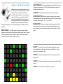
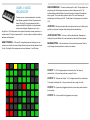
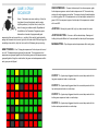
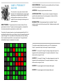
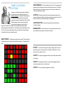
GAME SYSTEM
MANUAL
PITTSBURGH MODULAR SYNTHESIZERS
Chaotic and CV Sequencing Arcade
Packed with six unique multi-mode sequencers and a fully voltage controllable user interface, the Game
System is deep! Each game represents a different type of sequencing, from classic step sequencers, to
unique multi-dimensional clock dividers, to chaotic gate generators. Individual sequencers in the Game
System would make great standalone modules. Bundled together, they offer an entire arcade of sequencing
options, with lots of room for creativity.
A Unique Set of Controls
The Game System uses a thumb joystick and button press interface for fast and intuitive navigation of the
sequencers. Joystick movements and button presses are voltage controllable, inviting external CV and gate
signals to take control of the gaming experience. The Game System can also be computer controlled, freeing
the sequencers to shift and morph with the zeros and ones.
CONTROLS
CV/GATE INPUTS
GAME Button - Pressing cycles through the 6 sequencer games. Pressing
The CV/Gate inputs are used to emulate the usage of user interface controls and
automate control of the sequencers. Inputs are activated using any voltage (CV
or gate signal) that rises above the triggering threshold.
and holding for two seconds enables the settings menu.
MODE Button - Functionality of the Mode button is assigned based on the
selected game.
BUTTON Emulates pressing the JOYSTICK button.
RESET Button - Resets the open game.
MODE Emulates pressing the MODE button.
CLOCK Button - With the Game System set to use the internal clock, the
RESET Emulates pressing the RESET button.
Clock button works as a tap tempo button to set the tempo of the internal clock.
With the Game System set to use an external clock, the Clock button acts as a
clock divider for the incoming clock. A number appears in the lower left of the
display to show the selected clock division.
JOYSTICK - Functionality of the Joystick is assigned based on the selected
game.
JOYSTICK BUTTON - Functionality of the Joystick Button is assigned
based on the selected game.
CLOCK External clock signal input. Active only when Clock Mode is set to
External Clock.
LEFT Emulates moving the joystick to the LEFT.
RIGHT Emulates moving the joystick to the RIGHT.
UP Emulates moving the joystick UP.
DOWN Emulates moving the joystick DOWN.
GAME SYSTEM FONT
OUTPUTS
Because of the extremely low resolution display, the Game System has a
custom font for displaying information.
Functionality of the outputs are assigned based on the selected game. Output 1
and Output 2 can function as gate or CV outputs. Output 3 and Output 4 can
function only as gate outputs.
GAME 1: METEOR SHOWER
Meteor showers have inspired musicians since the
dawn of time. The Game System transforms these
celestial events into an 8x8 matrix filled with
pixelated meteors, explosions, and one panicked
spaceship. Pilot your unarmed ship through the
matrix while dodging falling meteors. Explosion
based gates and random control voltages react to
the action and provide the perfect score to the
amazing events taking place in the simulated night sky. God speed, fearless
astronauts.
HOW IT WORKS - Two types of gates are triggered based on different
USER INTERFACE - Meteors are represented by green LEDs. The cursor
(spaceship) is represented by a red LED. Meteor explosions are yellow and
spaceship explosions are red.
JOYSTICK - Moving the joystick moves the red cursor (spaceship).
JOYSTICK BUTTON - Sets the maximum number of active meteors. A
number appears in the lower left of the display to show the maximum number
of meteors. Options include 1, 2, 3, 4, 5, 15, and 25.
MODE BUTTON - Enables or disables red cursor autopilot mode. When
active, the red cursor will move around randomly. When disabled, the red
cursor will remain in one location unless moved with the joystick or CV/Gate
inputs.
explosions. When the red cursor collides with a green meteor, Output 1 outputs
a random voltage and Output 2 sends out a gate. When the green meteors
collide with the ground, Output 3 sends out a gate.
OUTPUT 1 - A random CV voltage. The voltage changes when the red
cursor collides with a green meteor. The output is calibrated to 1 volt per
octave and has a range of 5 volts.
OUTPUT 2 - A gate output triggered when the red cursor collides with a
green meteor.
OUTPUT 3 - A gate output triggered when a green meteor collides with the
ground.
OUTPUT 4 - A clock output that triggered on every step.
GAME 2: MUSIC
SEQUENCER
Create your own musical masterpiece, a melody
that defines a generation. Music Programmer is a
classic 32 step CV and gate sequencer that is
programmed with the joystick or auto generated
using control voltages. Sequences can vary in
length from 1 to 32 steps and can be played in forward, reverse, pendulum, or
random order. CV output is quantized to 1 volt per octave to keep the resulting
patterns well tempered.
HOW IT WORKS - A 32 step CV and gate sequencer. Each step can be
turned on or off and the output voltage for each step can be set between 0 and
5 volts. The length of the sequencer can be set between 1 and 32 steps.
USER INTERFACE - The user interface is split in half. The top displays the
sequencer grid. Active steps are green and inactive steps are not lit. The
bottom displays selected Mode in red and the output voltage of the selected
step in green. The current step marker is yellow. The cursor showing the
selected step is a blinking red LED. The last step of the sequence is a solid red
LED.
JOYSTICK - Moving the joystick left and right moves the cursor. Moving the
joystick up and down changes output voltage of the selected step.
JOYSTICK BUTTON - Turns on or off the selected step. Pressing and
holding the Joystick Button for 2 seconds sets the last step of the sequence.
MODE BUTTON - Sets the direction of the current step marker. Press to
cycle through forward, pendulum, reverse, and random.
OUTPUT 1 - A CV voltage based on the current step. The output is
calibrated to 1 volt per octave and has a range of 5 volts.
OUTPUT 2 - The same as Output 1. A CV voltage based on the current step.
The output is calibrated to 1 volt per octave and has a range of 5 volts.
OUTPUT 3 - A gate output triggered when the current step marker lands on
a active step.
OUTPUT 4 - A clock output that triggered on every step.
GAME 3: DRUM
SEQUENCER
Hmm.... Percussion can mean anything. A short (or
long) burst of sound (or silence) used to create
rhythmic patterns (or not) that drive (or don't) the
beat of a song (or endless noodle). Regardless of
the definition, the Percussion Programmer game
features four channels of programmable gate
sequencing that can be used for, um... anything. Rock and roll would probably
assign the channels to kick, snare, high hat, and crash while EDM would go with
something closer to kick, high hat, kick, and kick. Whatever gets you moving…
USER INTERFACE - The user interface is split into four sequencer grids.
Active steps are green or red and inactive steps are not lit. The current step
markers for each sequencer are yellow. The cursor showing the selected step
is a blinking yellow LED. If the sequence is red, the last step is marked with a
green LED. If the sequence is green, the last step of the sequence is marked
with a red LED.
JOYSTICK - Moving the joystick left, right, up, down moves the cursor.
JOYSTICK BUTTON - Turns on or off the selected step. Pressing and
holding the Joystick Button for 2 seconds sets the last step of the sequence.
MODE BUTTON - Flips the green and red sequencers within each group.
HOW IT WORKS - Four 16 step gate sequencers. Each step can be turned
on or off. The sequencers are grouped into two sets. The top green and red
sequencers are grouped together and the bottom green and red sequencers are
grouped together. Using the mode button, the green and red sequencers within
each group can be flipped.
OUTPUT 1 - A gate output triggered when the current step marker for the
top green sequencer lands on a active step.
OUTPUT 2 - A gate output triggered when the current step marker for the
top red sequencer lands on a active step.
OUTPUT 3 - A gate output triggered when the current step marker for the
bottom green sequencer lands on a active step.
OUTPUT 4 - A gate output triggered when the current step marker for the
bottom red sequencer lands on a active step.
GAME 4: TIME TRAVELLER
A way to be in four places at once. Time Traveller is
the first two dimensional clock divider. A game that
shifts outputs freely within clock divisions and
offsets. Four independent clock divider outputs
allows for multiple divisions at the same time. Time
travel can be complicated; don't forget your towel.
HOW IT WORKS - Using the idea of a time grid, clock divisions from 1 to 8
are laid out on the x axis. The first column divides the clock by 1. The second
column divides the clock by 2, the third column divides the clock by 3 and so on
up to the last column dividing the clock by 8. The y axis sets offset. The top row
outputs without offset. Moving down each row adds 1 clock step of offset to the
output. The four outputs can be independently set to a static location, or
allowed to freely roam the time grid creating unpredictable results.
USER INTERFACE - Clock divisions are represented by green LEDs. The
red LED represents the selected output. The Yellow LEDs represent the
unselected outputs.
JOYSTICK - Moving the joystick moves the selected red output.
JOYSTICK BUTTON - Cycles through the outputs. The selected output is
represented by a red LED. A number appears in the lower left of the display to
show the selected output.
MODE BUTTON - Enables or disables output roaming mode. When active,
the output will move around randomly. When disabled, the output will remain in
one location.
OUTPUT 1 - A gate output triggered when the Output 1 LED overlaps a
green clock division LED.
OUTPUT 2 - A gate output triggered when the Output 2 LED overlaps a
green clock division LED.
OUTPUT 3 - A gate output triggered when the Output 3 LED overlaps a
green clock division LED.
OUTPUT 4 - A gate output triggered when the Output 4 LED overlaps a
green clock division LED.
GAME 5: PROBABILITY
MACHINE
The real world is a crazy place and music should
reflect that. The Probability Machine creates chaotic
gates based on a cascading chance algorithm. The
resulting patterns are always in sync with some
multiple of the clock, allowing for stuttering but not
disjointed patterns.
HOW IT WORKS - The game outputs two channels of random CV and
gates based on the clock. The gates are always triggered on a multiple of the
clock ensuring the patterns generated are musically useful.
USER INTERFACE - The tip of the red arrow defines the X and Y location
used by the cascading chance algorithm.
JOYSTICK - Moving the joystick moves the red arrow.
JOYSTICK BUTTON - There are 4 levels of complexity. Pressing the
joystick button selects the level. A number appears in the lower left of the
display to show the selected level.
MODE BUTTON - Switches between Mode 1 and Mode 2. Mode 2
enables computer control of the red arrow. Mode 1 disables computer control
of the red arrow.
The density of the gates is based on a two dimensional probability field. The X
axis defines the potential of an event. Moving to the right increases the potential
a gate will trigger. The Y axis defines the the complexity of the event. Moving
down increases the potential for a more complex event. The joystick button
adds additional layers of complexity to the outputs.
The outputs are paired together to provide a sync’d CV and gate source.
Output 1 is paired with output 3 and output 2 is paired with output 4. OUTPUT 1 - A random CV voltage. The voltage changes when output 3 is
triggered and the output flashes green. The output is calibrated to 1 volt per
octave and has a range of 5 volts.
OUTPUT 2 - A random CV voltage. The voltage changes when output 4 is
triggered and the output flashes red. The output is calibrated to 1 volt per
octave and has a range of 5 volts.
OUTPUT 3 - A gate triggered when the display flashes green.
OUTPUT 4 - A gate triggered when the display flashes red.
GAME 6: EUCLIDEAN
RHYTHMS
Impress your friends by applying all that geometry
you learned in school. Inspired by the paper by
Godfried Toussaint, the Euclidean Rhythms game is
an auto-generating gate pattern sequencer that
organizes complexity. Mathematically, the Euclidean
Rhythms sequencer works to evenly space the
number of active beats over the length of the
sequence. Musically, the Euclidean Rhythms effortlessly creates organic
patterns steeped in both Western and non-Western musical philosophies. Add a
bit of CV control to create sequences that evolve with the incoming voltages,
and suddenly math never sounded so good.
USER INTERFACE - The user interface is split in half. The top displays the
sequencer grid. Active steps are red and inactive steps are not lit. The bottom
displays the length of the sequence in green and the number of beats in red.
The current step marker is yellow.
JOYSTICK - Moving the joystick left and right changes the length of the
sequence. Moving the joystick up and down changes the number of beats. The
number of beats can not exceed the length of the sequence.
JOYSTICK BUTTON - Flips the active steps with the inactive steps
inverting the pattern.
MODE BUTTON - Sets the direction of the current step marker. Press to
cycle through forward, pendulum, reverse, and random.
HOW IT WORKS - The sequencer requires two numbers. The total length of
the sequence and the number of beats within the sequence. The algorithm will
then
OUTPUT 1 - A random CV voltage. The voltage changes when the current
step marker lands on a red active step. The output is calibrated to 1 volt per
octave and has a range of 5 volts.
OUTPUT 2 - A gate output triggered when the current step marker lands on
a active step.
OUTPUT 3 - The opposite of Output 2. A gate output triggered when the
current step marker lands on an inactive step.
OUTPUT 4 - A clock output that triggered on every step.
SETTINGS MENU
3: GATE LENGTH
Press and hold the Game button for 2 seconds to enter the setting menu. Move
the joystick left or right to cycle through the settings screens. Press the Game
button to exit the settings menu.
Sets the length of the output gates. Lengths available are 40ms, 80ms, 160ms,
240ms.
1: CLOCK SOURCE
4: FACTORY RESET
Select between internal and external clock. Resets all games and settings to their original state. Press up on the joystick
three times to perform a factory reset. A small explosion verifies the process is
complete.
If internal clock is selected, the Clock button functions as a tap tempo button to
control the tempo of the internal clock.
If external clock is selected, use the Clock jack to input an external clock
source. The Clock button acts as a clock divider for the incoming clock. A
number appears in the lower left of the display to show the selected clock
division.
2: DISPLAY BRIGHTNESS
5: STATIC VOLTAGES
Sets the brightness of the LED display.
The selected static voltage is sent to Output 1 and Output 2. This can be used
to calibrate the D/A converters of Output 1 and Output 2. To calibrate the
outputs, move the joystick up or down to select a voltage and adjust the output
channel trimpots until Output 1 and Output 2 match the voltage displayed.