1
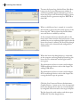
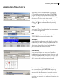
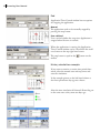
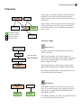
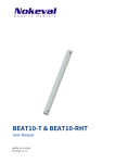
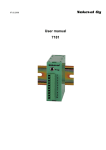
PromoLog User Manual
Nokeval
2 PromoLog User Manual
PromoLog User Manual
PromoLog version 1.0.454
Manual revision 7.9.2006
Copyright © Nokeval Oy. All rights reserved.
PromoLog User Manual 3
Contents
Preface ................................................................................................. 5
Introduction ........................................................................................... 6
Installing ............................................................................................... 8
Startup................................................................................................. 10
Language .............................................................................................. 13
Licensing .............................................................................................. 14
Application Time Control ........................................................................... 17
Channels ............................................................................................... 19
Sheets.................................................................................................. 25
Alarms ................................................................................................. 27
Nokeval SCL Connection Wizard ................................................................... 29
Nokeval MTR970/RTR970 Radio Data Receiver .................................................. 31
Nokeval Wireless Transmitters ..................................................................... 34
Troubleshooting ..................................................................... 40
Interface failure during startup ................................................................... 41
Device failure during startup ...................................................................... 42
Nokeval Wireless Transmitter module ............................................................ 44
Licensing .............................................................................................. 45
4 PromoLog User Manual
PromoLog User Manual 5
Preface
This manual is truncated version of the complete
PromoLog manual and attempts to provide a
quick and easy guide to help users get started with
PromoLog.
This manual may contain references to
chapters that only exist in the complete
version of PromoLog user manual. The
complete version can be downloaded from
www.nokeval.com/promolog.
Notation Conventions
The following notation conventions are used
throughout this manual.
Navigation
A menu selection and other types of selections will
have greater than signs indicating how to navigate:
Menu > Submenu > Selection
Fonts
This font indicates a parameter.
This font indicates a file name.
Symbols
This symbol incicates a note or a tip.
This symbol indicates something important.
6 PromoLog User Manual
Introduction
PromoLog is a modular data acquisition software allowing you to design customized applications matching
your needs.
Applications are created by dragging suitable modules from library onto the screen. Both wireless and wired
transmitters are supported without channel limits. You can also place photos or drawings on the background.
The modules are divided into six different classes: Input, Data Processing, Visualization, Recording, Output
and Network. The following block diagram shows some modules and how they can be linked.
Field instruments
Wireless
Receivers
I/O device
mA/V outputs
Transmitters
RS485 Serial Bus
USB/RS485
converter
RS232
USB
GSM modem
for alarms
TCP/IP connection for
remote PromoLog
RS232
PromoLog Software
Interface
for serial communications
The number of sheets is
unlimited.
Sheets 1
Sheets 2
Input channels
Input Module
Input Module
1 2 3 4 5 6 7 8
1 2 3 4 5 6 7 8
Input Module
1 2 3 4
Link connection
to other sheets
Link Display
Mathematic
Module
LinkDisplay
Display
Link
Link connection
to other sheets
Visualization
Mathematic
Module
Link Display
Mathematic
Module
Link Display
Link Display
Manual Input
To Output Module
Link Display
Data Recorders
Complex calculations can be made using the Mathematic Functions
module. The result is be displayed and can act as a source to other
modules
Input
1 2
Output Module
Data Processing
Recording
Review
Output
Several data recorders can
be used for saving data
Reports
PromoLog User Manual 7
Typical Application for PromoLog Software
Cold rooms
Area 1
ra
st
es
rel
Wi
rs
itte
m
ns
Receiver
RTR970
Repeaters can be placed near closed steel
cabinets to extend the distances between
transmitters and the receiver.
USB/
RS232
Area 2
PromoLog
Reports
RS
48
Alarms
i
Repeater
RTR960
5b
us
W
ra
st
es
rel
rs
itte
m
ns
Intranet or Internet
GSM-alarms
Dis
tan
ce
up
to
int s
ipo itter
t
l
Mu nsm
tra
1k
m
Area 3
Remote PromoLog
for reporting
PromoLog supports devices that use either
Nokeval SCL or Modbus RTU protocol.
Wi
re
dt
ran
sm
itte
rs
8 PromoLog User Manual
Installing
Installing PromoLog is easy. Start by locating the
installation package setup.exe. This package can be
obtained either from the Nokeval Software CD or
from the Nokeval Web Server at address:
http://www.nokeval.com/promolog/setup.exe
Run the installation program setup.exe. A welcome screen is shown. Proceed by clicking Next.
A system information screen is shown next. This
screen has information on the target computer system. PromoLog has certain minimum computer and
operating system requirements. This screen shows
which of these requirements are met. The minimum
system requirements are:
Operating System: Windows 2000 or Windows XP
RAM (Central memory): 128 MB minimum
Processor: 500 MHz minimum
USB ports or Serial COM ports required
PromoLog will install and may work on
systems with inferior specifications, but
this is not recommended nor supported by
Nokeval.
If the minimum system requirements are met, proceed by clicking Next.
PromoLog User Manual 9
Select the destination directory (folder) for
PromoLog. The default installation folder is:
C:\Program Files\Nokeval\PromoLog
When ready, proceed by clicking Next>.
This screen provides an opportunity to select which
optional components of PromoLog are to be installed. It is recommended to install all components.
When decided, finish the installation by clicking
Install.
10 PromoLog User Manual
Startup
Welcome Screen
Start PromoLog with the shortcut icon placed on
the desktop by the installation program. This shortcut is also added to the Windows Start Menu under
the program group Nokeval > PromoLog.
During PromoLog startup a splash screen of the
PromoLog Hardware Interface Layer (PHIL) is
shortly displayed. This is perfectly normal.
PromoLog main window will appear on the screen
in the welcome application state when the startup is
complete. It should look similar to the example on
the left-hand column.
Select New Application if you want to start building your own application or Open Application if you
want to open an existing application.
You can also start example applications to get more
familiar with PromoLog.
You can disable the welcome screen from the Show
Welcome Screen on Startup button.
To enable the welcome screen select File > Prefereces
and then set the Use Welcome Application parameter to Yes.
PromoLog User Manual 11
User Interface
Toolbar
Print active Sheet on the default Windows
printer.
Shortcut: Ctrl-P
Open Input Channel List window.
Open Output Channel List window
Open Alarm List window.
Shortcut: F8
Open Module Library window.
Shortcut: F6
Open Module List window.
Shortcut: F9
Open Time Control Panel.
Shortcut: Ctrl+F5
Start PromoLog Application
Shortcut: F5
Stop PromoLog Application.
Shortcut: F5
12 PromoLog User Manual
Sheets
Sheet tabs can be used to quickly select the active
Sheet.
C
A
E
G
Status Bar
B
D
F
A = Message Field
E = Script Status Field
B = Application Mode
F = License Status Field
C = Date and Time Field G = Processing Load Field
D = Alarm Status Field
Status Bar displays useful tips and important status
information.
Message Field
Displays status messages and usage tips depending
on the situation and the position of mouse pointer.
Application Mode
Displays ”Design”, ”Starting”, ”Simulating” or ”Realtime” depending on the Application operating mode.
Date and Time Field
• Design Mode: Displays the current date and time.
• Starting Mode: Displays progress percentage.
• Simulation Mode: Displays current simulated date
and time.
• Realtime Mode: Displays current date and time.
Alarm Status Field
Displays the number of active alarms. Click to open
Alarm list.
Script Status Field
Displays the number of running scripts. Click to
open Script Center.
License Status Field
Displays PromoLog license status. If the license cannot be validated, a red exclamation point is shown.
Click to open License Management window.
Processing Load Field
Displays approximate Application processing load
percentage and a scrolling graphical representation
of processing load during the past few seconds. Load
percentage should normally stay well below 50% to
ensure smooth operation. It is normal in multitasking Windows environment for the load to momentarily peak even at or above 100%.
PromoLog User Manual 13
Language
The main and default language in PromoLog is
English but some modules in PromoLog are multilingual.
To change the language used in these modules it is
necessary to change the Language parameter of the
application.
To do this, select Application Setup from the Design
menu or press F2.
Select the Language parameter from the left-hand
pane and then select the language you want.
Press the close button to exit the parameter editor
window.
14 PromoLog User Manual
Licensing
After the first startup, PromoLog is working in
demo mode. PromoLog is fully functional in demo
mode and all modules and features can be freely used
and tested. The only limitation is that the application
can be run in the active mode for only 5 minutes at a
time.
If you have already purchased a license for
PromoLog, then you can start licensing your copy of
the software immediately. Licensing operations are
done in the License Management window. To open
this window, select menu Operate > License.
Another way to open the License Management window is to click the License panel in the status bar.
Read on to learn more about PromoLog licensing.
Nokeval devices that can be used as dongles
• USB to RS485 Converter DCS770 (USB)
• USB to RS485 Converter DCS771 (USB)
• USB to POL Converter DCS772 (USB)
• RCS770 USB / RS485 / RS232 converter (USB)
• Radio Data Receiver MTR970 (SCL)
• Radio Data Receiver RTR970 (USB/SCL)
• Radio Receiver with Logger
RTR970PRO (USB/SCL)
• 16 Channel Transmitter RMD680 (SCL)
• 2 Channel Transmitter 6821 (SCL)
• Strain Gauge Transmitter 6841 (SCL)
• Programmable Transmitter7100 (SCL)
• I/O Transmitter 7181 (SCL)
PromoLog licenses are based on license keys. Each
key is bound to and authorized by a hardware
dongle.
Various Nokeval serial transmitters and converters
can also function as hardware dongles for PromoLog
license keys. So, in most cases, a dedicated license
key dongle is not needed. Instead, the license key can
be bound to one of the serial transmitters or converters that are connected to the computer running
PromoLog.
PromoLog User Manual 15
To use a USB device for license key authorization, it
is enough to connect the device to the computer and
install the USB drivers.
To use an SCL device, it is necessary to connect
it to the computer and fully configure it for use in
PromoLog. Read more about how to do this from
the chapter discussing the device type in question.
For example, if you are using Nokeval 7100 transmitter see the chapter Nokeval Serial Transmitter.
The License Management window is divided into
two frames. The upper frame has a list that shows
the entered license keys and two buttons for adding
and removing them.
The lower frame shows the licensing status of the
current application versus the available and authorized licenses. This frame also provides contact information for obtaining or upgrading a software license
for PromoLog.
To license your copy of PromoLog, check that you
have the PromoLog Software License Agreement
which bears the license key, and the associated license key dongle device at hand.
To identify the correct license key dongle
device, you need to check the serial number
of the device. The license key begins with the
serial number of the associated dongle device.
16 PromoLog User Manual
To enter the license key, click the Enter New Key...
button on the License Management window. A
small entry window appears, prompting to enter a
license key. Type in the license key, exactly as printed on the license agreement and press ENTER or
click OK.
When a valid license key is entered, it is stored in
the PromoLog license key file and it appears in the
license key list. The list shows the channel allowance and licenses enabled by each key.
In this example, the license level check list in the
lower frame shows that the Lite level license is now
available but not yet authorized (the light beside the
license level name is yellow). The license key dongle
device needs to be connected and configured for
authorization.
When the license key dongle device is connected
to the computer and recognized by PromoLog, the
license level is authorized and the light beside it
turns green.
For information on how to connect and configure
USB based dongle devices refer to the chapter Installing USB drivers.
For information on how to connect and configure
SCL based dongle devices refer to the chapter discussing the device type in question.
Click the List Connected License Authorization
Capable Devices... button to see a list of recognized
license key dongle devices that are currently properly configured and connected to the target computer.
The list shows the serial numbers and device types
(USB or SCL) of the dongle devices.
PromoLog User Manual 17
Application Time Control
Application Time Control window is mainly used
to control the recovery of data from RTR970PRO
receiver and binary channel data saved to hard disk
by PromoLog. It can be also used to schedule the application to run for a certain time period.
Open the Application Time Control window by
clicking the
icon on the toolbar or by pressing
Ctrl+F5.
Begin
Application Time Control window has three options
for starting the application.
Now
No data is loaded from the flash memory of the
RTR970PRO receiver nor from hard disk.
Automatic
PromoLog detects the latest value that has not been
loaded from the flash memory of the RTR970PRO
receiver and runs time simulation from that moment.
Also binary channel data from hard disk will be
processed from that moment forward.
User defined
User can freely define the start time. PromoLog
loads data from that moment forward from the flash
memory of the RTR970PRO receiver and runs time
simulation. Also binary channel data from hard disk
will be processed from that moment forward.
Time simulation in PromoLog means that data that
was recovered from the RTR970PRO receiver or
from binary channel data files is processed equally as
data received when PromoLog is normally running.
The amount of this data can be quite large and
therefore the simulation can take quite a long time in
some cases.
18 PromoLog User Manual
End
Application Time Control window has two options
for stopping the application.
Manual
The application needs to be manually stopped by
pressing the stop button.
User defined
User can freely define the stop time. Application is
stopped when the time is reached.
When the application is running the Application
Time Control window can be closed from the small
cross button at the top right-hand corner.
The stop button is equal to the
toolbar.
button on the
History simulation example
If you want to examine a certain time period afterwards, select the wanted start and stop times and
start the simulation.
In the example picture on the left-hand column a
four hour period two days ago was chosen.
After the time simulation all channels PromoLog are
in the same state as they were two days ago.
PromoLog User Manual 19
Channels
Nokeval Wireless
Transmitter
Link Display
Manual Input
Mathematic
Function
Single Trend
Plotter
PromoLog is a modular program and data between
modules is mainly transferred through channels.
Also parameter values can be used as data sources in
some cases.
One module can have several channels and the type
of the channels can vary. The pictures on the lefthand column shows some examples how channels
can be used.
Data Buffer channel
Data Source channel
Data Link channel
Link Display
Parameter value
Channel types
Data Source
Nokeval 6821
2 channel transmitter
USB/RS485
converter
Interface
for serial communications
Modules that provide data themselves have Data
Source channels.
Field instruments
PromoLog Software
Nokeval Serial
Transmitter
6821
Most of the modules in the input category in
PromoLog have Data Source channels but also Data
Processing modules produce data and have Data
Source output channels.
For example, the type of the input channel of the
Nokeval Serial Transmitter module is Data Source.
Data Source channels have a ring buffer that can be
accessed by Data Link channels.
Data Buffer
Nokeval Serial
Transmitter
6821
Manual Input
Single Trend
Plotter
Single Trend
Plotter
Data Buffer channels are channels that record the
value of a selected parameter or channel with given
interval. For example, Single Trend Plotter has a
Data Buffer channel.
Data Buffer channels also have a ring buffer that can
be accessed by Data Link channels.
20 PromoLog User Manual
Data Link
Nokeval Wireless
Transmitter
Link Display
Single Trend
Plotter
Link Display
Data Link channels do not have their own buffers.
Data Links are pure links to Data Source channels,
Data Buffer channels or to parameters.
If the source of a Data Link channel is an unbuffered
parameter value, only the latest value is available for
the Data Link channel. Because of this, for example,
a Link Display module cannot plot graphs for unbuffered parameters but Single Trend Plotter can.
The advantage of using modules with Data Links
instead of Data Buffers, is smaller memory consumption.
Channel type
Channel name
Channel Settings
Configuring different channel types in PromoLog
is quite similar. This example assumes that a Single
Trend Plotter module is created as instructed on
page 82.
To view the channel’s settings double-click the
module when the application is stopped and select
the
parameter from the left-hand pane.
A source for Data Buffer and Data Link channels
can be linked using the Y Source button. Linking the
channels is explained next in this chapter.
The Value button opens the Channel Buffer Window that can be used to export and print channel
values. The Channel Buffer Window is explained at
the end of this Chapter.
Channel values can be logged to hard disk by selecting the Log to file check box. For more information,
see page 120.
PromoLog User Manual 21
Linking channels
There are two different ways to link channels. In
other chapters of this manual only Resource Browser
is used because it is capable of linking all possible
sources.
Input Channels
Output Channels
1. Drag&drop
Input channels are commonly used as sources to
other modules. The fastest and easiest way to link
these channels is by dragging the channels directly to
the destination module’s
parameter page.
Open the Input Channels window by clicking the
button on the toolbar. Open also the destination
module’s parameter editor and select the
parameter.
In the example pictures on the left-hand column, a
input channel is added to a Data Recorder module
and to a Multi Trend Plotter module.
Modules where the number of channels is not fixed
have an area where channels can be dropped to automatically create new channel to the module.
Select the input channel you want to add from the
Input Channels window. Then drag the selected
channel over the “Drop object here to create a new
Channel” text and drop the object.
In modules where the number of channels is fixed
select the wanted
parameter and drop the object
to the Y Source field.
Also Output channels can be equally linked. Note
that only input and output channels can be linked
using this method although other parameter values
are also supported as inputs.
22 PromoLog User Manual
2. Resource Browser
Click the Y Source Button to open the Resource
Browser window. Resource Browser is a tool for linking PromoLog’s resources to channels. All channels
and parameters can be selected as a source using the
Resource Browser. Resource Browser cannot be used
for editing parameter values.
Toolbar
Pick
Use the Pick button to set the selected resource as a
source.
Cancel
Use the Cancel button to close the Resource Browser
without changing anything.
Find
You can search all resources using a key word using
the find button. Type in the search phrase to the Ref.
text box and click the Find button. All matching
resources are highlighted using red color.
Find Ref
This option is for advanced users. You can find a
resourcce from the parameter tree by typing the corresponding reference, for example
CMTRTransmitter#104=Input, to the Ref. text box.
Refresh
The refresh button rebuilds the whole resource tree
of the selected source.
When using Remote Access Client you can choose
remote PromoLog as a source from the Source dropdown menu.
PromoLog User Manual 23
Resource tree
The resource tree is divided into two main branches.
The PromoLog branch marked with
contains
program wide parameters that are rarely used as
inputs to other modules.
The Application branch marked with
contains
application wide resources including all sheets and
modules. The Modules subbranch marked with
contains all modules in the application.
If the selected resource is valid as a source the background color of the Ref. field is green.
To open the Resource Browser select the wanted
parameter and press the Y Source button.
Select the input source that you want from the resource tree and click the pick button.
The green background color on the Ref. field indicates that the source is valid and red respectively
indicates an invalid source. The background is blue if
the channel is linked to a parameter called Nothing.
24 PromoLog User Manual
Channel Buffer Window
The Channel Buffer window can be opened by
pressing the Value button. This window lists all values from the buffer with time stamp.
Toolbar
Find
This button moves the time defined by date and time
boxes to topmost in the view.
Export
Use this button to export channel values to a text file.
Pressing this button opens a new window where
more specific parameters are set.
Print
Use this button to print channel values to default
printer.
Export/Print Channel Data
Some parameters cannot be changed when printing
channel values.
Begin and End fields are used to select the time
period to export or print.
File Format
• ASCII Text: Data is saved in ASCII text format.
• Binary: Data is saved in binary format.
Time Format
• General Date: dd.mm.yyyy hh:mm:ss
• Decimal: days from 30.12.1899, e.g. 38965.56
Number Format
This setting defines the number formatting.
Dec. separator
Pediod or comma can be selected as a decimal separator.
Field separator
Tab, Semicolon, Colon or Backslash can be selected
as a field separator.
Record separator
CRLF, CR, LF or Tab can be selected as a record
separator.
PromoLog User Manual 25
Sheets
To add or otherwise manipulate sheets, select menu
Design > Sheets... or press F3.
Adding
Click the blue plus button to add a new sheet. The
new sheet will appear at the end of the sheet list.
A new sheet tab will also appear in the PromoLog
main window’s sheet tab row.
Organizing
To change the order of the sheets, select the sheet
you want to move on the list and click the up or
down arrow buttons. Changes in the sheet order can
immediately be seen also in the sheet tab row on the
PromoLog main window.
Deleting
To delete a sheet, select the sheet you want to delete
and click the red cross button. You will be asked to
confirm the deletion because this operation cannot
be undone.
Editing
To edit sheet parameters, click the index finger button or double-click the sheet’s name on the sheet
list. To quickly rename the selected sheet, click its
name on the list. The sheet name can now be edited
on the list. When ready, press ENTER.
26 PromoLog User Manual
Parameters
Name
A common parameter for all PromoLog objects.
Sheet’s name is displayed on the sheet tab in the
sheet tab row on the PromoLog main window.
Information
Additional sheet information. This information is
shown on the sheet list.
Lock when Activated
If Yes, the sheet will be locked when the application
is activated.
Locked
If Yes, the sheet is locked. Module displayed on the
sheet cannot be moved or resized.
Sheet Background Color
Color setting for the sheet background.
Image
Sheet background bitmap image file.
Autosize
If Yes, the sheet will automatically take the size of
the background bitmap image.
Width, Height
Width and height of the active sheet area in pixels.
Left, Top
Position memory for the horizontal and vertical
scrolling bars of the sheet.
Horizontal Grid, Vertical Grid
Horizontal and vertical grid spacing in pixels. This
grid can be used to align module displays on the
sheet.
Print Orientation
Paper orientation to use when printing the sheet.
PromoLog User Manual 27
Alarms
PromoLog shows all active alarms in the Alarm List
window. You can open the Alarm List window either
by clicking the
button on the toolbar or by pressing F8.
Edit channel host parameters
Edit channel parameters
Acknowledge alarm
Alarm message
Alarm parameters
Alarm parameters can be defined individually for all
channels.
Advanced parameters are marked with
icon in
the parameter tree. To enable visibility of these parameters press down the
button.
Both High and Low Alarms have the same
parameters.
Enabled
Yes = alarm is enabled
No = alarm is disabled
Limit
When the channel value exceeds the limit value the
alarm is activated.
Alarm limit
Hysteresis
Hysteresis
If the limit value is exceeded, the channel reading
must drop below the limit value plus or minus hysteresis before the alarm is cleared.
This prevents alarm from cycling on and off when
the channel reading is close to the limit value.
Alarm activated Alarm cleared
Delay
Alarms do not appear in the report generated by a
Surveillance Report module until the delay time has
expired.
28 PromoLog User Manual
Remote Target
The phone number to which the alarms will be sent.
If defined, this parameter overrides the General
Alarm Target parameter of the Surveillance Report
module.
Report Message
This is the message shown in the Message field of
the Alarm List window. The message is also added to
a report generated by a Surveillance Report module
if the alarm occurs.
Cancel Message
This message is added to a report generated by
a Surveillance Report module when the alarm is
cleared.
Acknowledge Alarms
When the alarm is activated this parameter is set to
No by PromoLog. When the alarm is acknowledged
by user this parameter is set to Yes.
Alarms can be acknowledged by selecting an alarm
and pressing the
button on the toolbar. Acknowledged alarm is shown in the Alarm List window as
long as the channel reading exceeds the limit value
but it is not counted as an alarming channel.
A message is added to a report generated by a Surveillance Report module when an alarm is acknowledged.
Sound alarms
PromoLog can play wav audio files when alarm
events occur. To enable sound alarms, select
Application Setup from the Design menu or press
F2. Then press down the
button to enable visibility of the advanced parameters.
Sounds > Alarm Report
Click the browse button next to the text box and
browse to the file you wish to play when an alarm is
reported. Other audio files are linked equally.
Sounds > Alarm Cancel
This audio file is played when the alarm is cleared.
Sounds > Alarm Pending
This audio file is played repeatedly when one or more
alarms are pending.
PromoLog User Manual 29
Nokeval SCL Connection Wizard
Nokeval SCL Connection Wizard searches for SCL
devices that are connected to a USB port and automatically creates corresponding modules.
To start the Nokeval SCL Connection Wizard,
select Design > Wizard > Start Nokeval SCL Connection Wizard.
If you haven’t already added interfaces, SCL Connection Wizard asks if you want to create one now.
Click Yes to continue.
Select the interface you want to use. SCLWizard is
the default, if no interfaces were created before running the wizard.
Then select the USB device from the drop-down
menu and select the correct baud rate for the device.
Click Start SCL Device Scan button to start
searching for devices. Scan progress is displayed
in text field next to scan button. Scanning may be
aborted at any time by pressing the Stop SCL Device Scan button.
30 PromoLog User Manual
All found SCL devices are added to the list below
the scan button. To create a corresponding module
for the device, just drag and drop the module icon
onto the sheet or press the Create Module on the
active Sheet button.
Note that a separate Interface must be created
for each USB device.
PromoLog User Manual 31
Nokeval MTR970/RTR970 Radio Data Receiver
Nokeval Radio Data Receiver module is a module
for collecting data from Nokeval Radio Data Receivers.
Adding the module
To add a Nokeval Radio Data Receiver module
select 2. Inputs from the Design menu. This opens
the Input module library window.
Alternately, you can also use Nokeval SCL
Wizard to automatically add and configure
the module. See chapter Nokeval SCL Wizard on page 29. If you used the wizard tool,
jump to the paragraph Using the module.
Create a new Nokeval Radio Data Receiver module
by dragging the Nokeval Radio Data Receiver icon
onto the active sheet. Alternatively, you can also
press the blue plus button or double-click the name
of the module.
Double-click the module to open parameter editor
window.
32 PromoLog User Manual
Before the Nokeval Radio Data Receiver module
can be used, the interface and SCL address must be
configured.
When you select the Interface item from the menu
tree, a list of all interfaces is shown at the right side
of the window. Select the interface to which your
device is connected.
See the chapter Creating an Interface if you haven’t
already created the needed interface.
Select the Address subitem from the menu tree
and type in the SCL address of the device.
The receiver type updates automatically to
the menu when the application is running
and the module receives a response from the
device.
Click close button to exit parameter editor.
Device Name and status of
status the interface
Device type and
serial number
Latest response
from the device
Using the module
Nokeval Radio Data Receiver module doesn’t require
any configuration besides the serial communication
settings done while adding the module.
The Nokeval Radio Data Receiver module is divided
into two parts. The upper part shows status information about interface and receiver while the lower part
shows information about latest received data packets.
PromoLog queries new data packets only
while the application is running.
The following table explains the columns:
Field
Description
Age
Time from reception
Device Radio transmitter’s type
ID
Radio transmitter’s identification number
Signal Radio transmitter’s signal level in dBm
Battery Radio transmitter’s battery voltage in V
PromoLog User Manual 33
Module List button
Start! button
Stop! button
Click the Start! button to start the application and
also click the Module list button to open the Module
List window.
When the application is running, Nokeval Radio Data Receiver module automatically adds all
detected radio transmitters to the module list.
Some configuration options are disabled when the
application is running, therefore when all transmitters are listed, it is recommended to stop the application using the Stop! button to continue building your
application.
You can now view transmitter data by dragging the
modules from the module list onto the active sheet.
Alternatively, you can also select the module and
click the blue plus button.
To configure the transmitter module(s) see the chapter Nokeval Wireless Transmitters on page 34.
34 PromoLog User Manual
Nokeval Wireless Transmitters
Nokeval Wireless Transmitters
One Nokeval Wireless Transmitter module represents one wireless transmitter measuring channel.
One wireless transmitter can have one or more measuring channels. Compatible wireless transmitters
and their channel counts are listed on the left.
MTR260 (1 channel)
MTR262 (1 channel)
MTR264 (4 channels)
MTR265 (1 channel)
MTR165 (1 channel)
RTR860 (2 channels)
FTR860 (2 channels)
This chapter explains how to create and configure
these modules manually. Read the chapter Nokeval
MTR970/RTR970 Radio Data Receiver to learn
how to create these modules automatically.
Module Display
Toggle display size
The wireless transmitters supported by this module
have different characteristics and they produce
different types of measurement data. This must be
noted when configuring the corresponding module.
The graphical display is basically the same for all
transmitter types. The module can be configured so
that the transmitter and sensor types are shown on
the display as in the example.
Measurement unit Alarm limit Signal and battery
and sensor type
displays
level indicators
Name of the
module
Name of the input
channel
Value
display
Main features of the module display are a trend
graph and a large digital display of the most recent
measurement value. The display also features measurement unit, alarm limits, received signal level and
battery level indicators.
Active areas of the module are highlighted using
light blue. You can set the display time span, alarms
levels, minimum and maximum values of the value
axis directly by clicking the corresponding active area
in the module.
When you click an active area of the module, a small
entry window appears, prompting to enter a new
value.
Value axis Time axis
Alarm limits Sensor type
PromoLog User Manual 35
Nokeval Wireless Transmitter modules can be used
with all Nokeval MTR series wireless transmitters.
One module is needed for each wireless measuring
channel. These modules are usually created automatically by PromoLog as described in chapter Nokeval
MTR970/RTR970 Radio Data Receiver on page 31.
This chapter describes how to manually create and
configure the necessary modules. The configuration
includes setting the transmitter ID numbers.
Adding the module
To add a Nokeval Wireless Transmitter module,
select Module Library from the Design menu. This
opens the module library window.
Create a new Nokeval Wireless Transmitter module
by dragging the Nokeval Wireless Transmitter icon
onto the active sheet. Alternatively, you can also press
the blue plus button or double-click the name of the
module.
Double-click the module to open parameter editor
window.
36 PromoLog User Manual
Before the Nokeval Wireless Transmitter module
can be used, the transmitter’s ID number and type
must be set:
Select Transmitter parameter from the left-hand
pane and enter the ID number printed on the wireless transmitter you want to associate with this module. This unique transmitter identification number
binds the physical transmitter unit to the module
used in PromoLog to represent it.
The Transmitter > Type parameter is automatically
updated when data is received from the transmitter.
Select Name parameter from the left-hand pane and
enter a descriptive name for the measuring point the
transmitter unit will represent. This name will also be
displayed on the title bar of the module and in the
Module List window.
You may also want to make the wireless transmitter
type and identification number show on the module
display. To do this, enter the transmitter type and
ID number in the input channel name field. You can
format this text as you wish.
PromoLog User Manual 37
Parameters
Double-click the Nokeval Wireless Transmitter
module to open module’s parameter editor window.
Name
A common parameter for all PromoLog objects.
Module’s name is displayed on the top part of the
module window and in the Module List window.
Transmitter
Transmitter identification number. This number
(prefixed with ID) is printed on the label attached to
the transmitter unit.
Transmitter > Type
The type of the transmitter. This parameter is automatically updated when data is received from the
transmitter.
Transmitter > Reception Timeout
Maximum allowable time interval between receptions. If there are no receptions from the transmitter
within this time, a timeout condition is assumed and
---- is displayed instead of the last reading.
You can change the name of the input channel by
typing a new name to the Name text box on the
right-hand pane.
If you want to save the channel values to disk, check
the Log to file check box. For more information
about saving channels to disk see page 120.
> Display
The display type. Possible types are graph, digital
display, vertical bar, horizontal bar, vertical indicator
and horizontal indicator.
The Display parameter item has the following
subitems:
Number Format
The number of visible decimal digits.
Unit
The measurement unit that is shown on the
display, for example, in the sample pictures the
measurement unit annunciator is °C.
38 PromoLog User Manual
Time Span
Time span of the graph display
Maximum
Upper limit of the graph / bar / indicator display.
Time Span
Minimum
Lower limit of the graph / bar / indicator display.
> High/Low Alarm
Module’s alarm settings are done in this submenu.
Alarm items have two subitems:
Enabled
Yes = alarm is enabled
No = alarm is disabled
Limit
Limits are highlighted in the display as shown on
the left-hand column.
> Input Type
Select the sensor used with the transmitter. The type
of the sensor is shown in the module’s display. This
parameter is used to determine fault conditions.
To edit the limit values of User Defined sensor option, enable the visibility of advanced parameters by
pressing down the
button and edit High/Low
Limit parameters. Fault text is displayed if the channel reading exceeds these values.
> Report
This parameter controls whether the readings are
included to a report generated by a Surveillance Report module or not. If a Surveillance Report module
doesn’t exist this parameter has no effect.
Never the value is never included
Alarms the value is included when an alarm is
triggered or canceled
Always the value is always included
PromoLog User Manual 39
> Use
If you are using the transmitter for temperature
monitoring you can select pre-defined settings for
the module using the option list on the right-hand
pane. MTR260 Transmitter modules display this
text in the module window instead of the sensor
type.
> Linearization
This parameter is only used for transmitters
with thermocouple sensor. Select the type of
the thermocouple used from the option list
on the right-hand pane.
RTR970PRO radio receiver with logger can
also be used to calculate the linearization. If
you have configured the RTR970PRO to
calculate the linearization for the transmitter
in question, set this parameter to None.
MTR970 and RTR970 radio data receivers
cannot be used to calculate linearization.
40 PromoLog User Manual
TROUBLESHOOTING
Interface failure during startup
Device failure during startup
Nokeval Wireless Transmitter
Licensing
PromoLog User Manual 41
Interface failure during startup
The most common reason for this error is a wrongly
configured interface.
Open the Communication Interface setup window
from Design > 1. Interface to see the more specific
error message.
USB failure: Device Serial Number not set
The Serial Number parameter configured for the
interface is blank.
Double-click the module and select the Serial
Number parameter from the left-hand pane. At the
right-hand pane is now listed all found USB devices
that you can use. Select the correct device from the
list and close the parameter editor window.
USB error: Device not found when opening device
with Serial Number...
The Serial Number parameter configured for the
interface doesn’t match any found device. This may
happen if you opened a demo application that contained USB interfaces.
Double-click the module and select the Serial
Number parameter from the left-hand pane. At the
right-hand pane is now listed all found USB devices
that you can use. Select the correct device from the
list and close the parameter editor window.
42 PromoLog User Manual
Device failure during startup
The most common reason for this error is an input
module that has the interface configured wrongly.
Click the More details button to see what module
caused the problem.
Double-click the line describing the problem to
open the module’s parameter editor. Open also the
Communication Interface setup window from Design > 1. Interface.
The following error messages are possible:
Device interface not available
This means that no interface is defined for the
module or the interface defined no longer exists.
In the module’s parameter editor window, select the
Interface parameter from the left-hand pane and
then select the correct interface from right-hand
pane. If you haven’t created the interface yet, see the
chapter Creating an Interface on page.
Device interface closed
The interface that is defined for the input module is
disabled. Enable the interface by checking the box
in front of the module’s name in the Communication Interface Setup window.
PromoLog User Manual 43
Device is not responding.
PromoLog did not receive any response from the
device. Check that the module’s Baud Rate parameter matches the device’s settings. This error also
occurs if the Interface > SCL > Address parameter
is incorrect.
If these parameters are correctly set the problem is
probably in the physical connections.
Error opening interface
PromoLog was unable to open the interface defined for the input module. This usually means that
same resources are used by some other interface in
PromoLog or some other program.
See the more specific description from Message field
in the Communication Interface Setup window.
Hardware error: Invalid port number
The COM port defined for the interface does not
exist. Double-click the interface’s name and select
the COM Port parameter from the left-hand
pane. Then use the AutoScan button to search for
all available ports and type in the correct COM
port number.
Hardware error: Invalid port already open
The COM port defined for the interface is already
open. Check that no other interface in PromoLog
or program is using the same COM port.
44 PromoLog User Manual
Nokeval Wireless Transmitter module
Incorrect reading when using thermocouple sensor
The value displayed in Wireless Transmitter module
is close to zero if the transmitter is in room temperature and the Linearization parameter of the module
is se to None.
If the sensor is not attached and the Linearization
parameter of the module is se to None, the value
displayed is over 700.
Open the module’s parameter editor window and select the Linearization parameter from the left-hand
pane. After that select the linearization matching
your sensor type from the right-hand pane.
For more detailed instructions how to configure the
module see the instructions on page 34.
Fault text
The Fault text is displayed if the channel reading
exceeds the limits determined by the Input Type parameter. Fault condition may be caused by a broken
sensor wire or a loose sensor connection.
Make sure that the sensor is properly attached and
the correct Input Type is chosen.
If the problem still exists, contact the manufacturer
for service.
PromoLog User Manual 45
Licensing
Unlicensed operating time expired
Before reading further, make sure that you have
entered the license key as instructed on page 14.
This solution only applies if you are using Nokeval
Serial Converter (DCS770, DCS771, DCS772 or
RCS770) as a license dongle.
Using Nokeval Serial Converter as a license dongle
requires that USB is selected as a transport layer for
the serial interface.
Transport Layer is set to COM
To check this, stop the application and open
the Communication Interface Setup window by
selecting Design > 1. Interfaces.
If the transport layer is set to COM, delete the interface using
button. Then press the
button to
add a new interface.
Name the new interface exactly as the deleted interface. In this way you do not have to change the
interface in input modules. Select USB as a transport
layer and press OK button.
Double-click the name of the interface that was just
created to open the interface’s parameter editor.
Select Serial Number parameter from the left-hand
pane and then the correct serial number from the
right-hand pane. Set also the correct Baud rate for
the device.
Close the parameter editor window and the Communication Interface Setup window using Close
buttons.
Now the interface is recreated using USB as a transport layer and PromoLog is able to authorize the
license key.