1
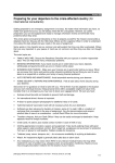
Page 12
RPA-1 User Manual
RPA-1 User Manual
RPA-1 Preamplifier
User Manual
DXE-RPA-1-INS-Revision 0
P A T E N T
P E N D I N G
©DX Engineering 2004
P.O. Box 1491 · Akron, OH 44309-1491
Phone: (800) 777-0703 ·Tech Support and International: (330) 572-3200
Fax: (330) 572-3279 · Email: [email protected]
Page 2
RPA-1 User Manual
Table of Contents
INTRODUCTION
Additional Requirements ........................................................................ 4
SPECIFICATION
Specifications Glossary .......................................................................... 5
Third Order Intercept ................................................................................ 5
THEORY OF OPERATON
Special Features of the RPA-1 .............................................................. 7
INSTALLATION AND MAINTENACE
Mounting........................................................................................................ 8
Mounting at the antenna .................................................................................... 9
Determining the sensitivity ................................................................................. 9
Connecting the power supply............................................................................. 9
Powering through the coax .............................................................................. 10
Reducing gain .................................................................................................. 10
Maintenance ............................................................................................... 11
Lightning .......................................................................................................... 11
WARRANTY
Warranty ...................................................................................................... 12
RPA-1 User Manual
Warranty
Technical Support
Page 11
5
I
f you have questions about this product, or if you experience difficulties during the
installation, contact DX Engineering at (330) 572-3200. You can also e-mail us at
[email protected]. For best service, please take a few minutes to
review this manual before you call.
Warranty
All products manufactured by DX Engineering are warranted to be free from defects in material and workmanship for a period
of one (1) year from date of shipment. DX Engineering’s sole obligation under these warranties shall be to issue credit, repair
or replace any item or part thereof which is proved to be other than as warranted; no allowance shall be made for any labor
charges of Buyer for replacement of parts, adjustment or repairs, or any other work, unless such charges are authorized in
advance by DX Engineering.
If DX Engineering’s products are claimed to be defective in material or workmanship, DX Engineering shall, upon prompt
notice thereof, issue shipping instructions for return to DX Engineering (transportation-charges prepaid by Buyer). Every such
claim for breach of these warranties shall be deemed to be waived by Buyer unless made in writing.
The above warranties shall not extend to any products or parts thereof which have been subjected to any misuse or neglect,
damaged by accident, rendered defective by reason of improper installation, damaged from severe weather including floods, or
abnormal environmental conditions such as prolonged exposure to corrosives or power surges, or by the performance of
repairs or alterations outside of our plant, and shall not apply to any goods or parts thereof furnished by Buyer or acquired
from others at Buyer’s specifications. In addition, DX Engineering’s warranties do not extend to other equipment and parts
manufactured by others except to the extent of the original manufacturer’s warranty to DX Engineering.
The obligations under the foregoing warranties are limited to the precise terms thereof. These warranties provide exclusive remedies,
expressly in lieu of all other remedies including claims for special or consequential damages. SELLER NEITHER MAKES NOR
ASSUMES ANY OTHER WARRANTY WHATSOEVER, WHETHER EXPRESS, STATUTORY, OR IMPLIED, INCLUDING
WARRANTIES OF MERCHANTABILITY AND FITNESS, AND NO PERSON IS AUTHORIZED TO ASSUME FOR DX
ENGINEERING ANY OBLIGATION OR LIABILITY NOT STRICTLY IN ACCORDANCE WITH THE FOREGOING.
©DX Engineering 2005
DX Engineering®, DXE®, Hot Rodz™, Maxi-Core™, Antenna Designer™, Yagi Mechanical™, and Gorilla
Grip™ Stainless Steel Boom Clamps, are trademarks of PDS Electronics, Inc. No license to use or reproduce any
of these trademarks or other trademarks on this web site is given or implied. All other brands and product names
are the trademarks of their respective owners.
Page 10
RPA-1 User Manual
RPA-1 User Manual
1
To reduce gain, cut a
lead from C3 and C6.
See page 9.
To reduce gain, solder a 1500 Ω resistor
in parallel with R1
and another with R6.
See page 9.
To reduce gain, solder a 1500 Ω resistor
in parallel with R1
and another with R6.
See page 9.
Unsolder RFC1 lead that connects to power jack, and then
reconnect to center pin of the
RF output jack. See page 9.
To reduce gain, cut a
lead from C6 and C3.
See page 9.
Figure 3. Circuit board illustrates how to reduce the gain and power the unit through the coax.
Maintenance
The RPA-1 requires virtually no maintenance as long as the unit is not exposed to direct sunlight,
moisture, or extreme temperatures. But as with any electrical device, lightning is a concern.
Lightning
While most amateur radio operators rarely suffer damage from lightning (even though they never
disconnect their equipment), the best protection is to disconnect electrical devices during storms.
The key to proper lightning survival is proper grounding of feedlines and equipment, and
maintaining integrity of shield connections. A proper installation improves lightning protection
and enhances weak-signal receiving performance. Consult lightning protection and station
grounding information in the ARRL handbooks, the NAB Broadcast Handbook or other reliable
sources.
Page 3
Introduction
C
ongratulations on your purchase of the RPA-1 receiver preamplifier. Its unique
combination of push-pull design and robust components provides significantly better
performance than other preamplifiers on the market, so we know you are anxious to get
started. Before you install the RPA-1, take a few minutes to read this brief user guide and
familiarize yourself with the installation, operation and safety procedures. We are confident that
you will find this preamp easy to use and that it will reward you with years of faithful service.
Additional Requirements
Please note you will need the following items (not included in this package) to install and operate
the RPA-1 receiver preamplifier:
Power Source The RPA-1 requires a negative ground, 10-18 Vdc @200mA min power
source that is not included. Depending on the supply current, you might also need an
inline fuse. Powering the RPA-1 through the coax feedline requires a voltage injector
circuit or a DX Engineering FVI-1 Voltage Injector that includes a power supply. Refer to
Connecting the Power Supply on page 9 for details.
Sealant If you opt to mount the unit outdoors, you will also need a silicon-based sealant,
such as 100% pure silicone RTV (DX Engineering part number RTV598335). Refer to
Installation and Maintenance at the top of page 8 for complete information.
RPA-1 User Manual
Page 4
Specifications
T
RPA-1 User Manual
2
he specifications in the table below represent typical performance from the RPA-1
preamplifier:
Power Requirement: 10-18 Vdc @ 140 mA maximum
Output TOI (Third Order Intercept): +43 dBm @ 13 Vdc
Noise figure: 3.5 dB
One dB Compression: +26 dBm (~ .4 watts output)
Gain: 16 dB from 300 kHz to 35 MHz (+1.5 to −1.5 dB over this range)
500 Hz BW IM3 Dynamic range: 110 dB or greater
Page 9
The RPA-1 power connector uses a standard 2.1mm barrel type plug. (included) A
traditional 500 mA, or larger “wall wart” with 12 Vdc negative-to-shell plug wiring, is
generally adequate for powering the RPA-1. You can also use a larger, regulated supply
provided it supplies 10-18 Vdc negative ground, has the power plug shell connected to
negative, and has an inline 1A fuse. WARNING! Be sure the supply polarity and voltage are
correct.
Powering through the coax
The external power connector is normally active, but components are inside the RPA-1 to allow
powering through the coaxial feedline. To change the power feed, refer to Figure 3 at the top of
next page, and do the following:
Caution: Do not nick, scratch, or break the fine wires on the choke. Do not grab the choke body
with pliers.
1. Unsolder the 100 uH RF choke lead that connects to the power jack.
2. Connect the free choke lead to the PC board indicated by the choke outline.
NOTE: A 12-18-Vdc positive power source must be inserted in the feedline center conductor through a
Specifications Glossary
The following are simplified explanations of the specifications highlighted in the table above.
Third Order Intercept A standard measure of how well a receiving system performs in the
presence of strong nearby signals. The higher the third order intercept (TOI), the less likely
adjacent strong signals will cause interference. The RPA-1 offers substantially improved TOI over
competitive preamplifiers and communication receivers.
Noise Figure The ratio of equivalent noise power developed at the input to that generated by
thermal noise in the source resistance, usually expressed in decibels. If it were possible, a perfect
amplifier would have a noise figure of 0 dB. The RPA-1 is extremely quiet, and does not
contribute noticeable noise to receiving systems.
Dynamic range The ratio of the faintest signal detected to the loudest signal amplified without
significant distortion, typically expressed in decibels. The RPA-1 allows you to hear faint signals
in the presence of adjacent strong signals.
Gain The ratio of signal input to output. The RPA-1feautures a high gain that is easily reduced if
not needed.
similar 100 uH choke and the voltage must be blocked from appearing at the receiver. A DX
Engineering FVI-1 voltage injector. which includes a power supply, can also be used.
Reducing gain
If signals are overloading your receiver or if background noise is excessively high, there are two
solutions. The first solution involves adding a conventional attenuator pad either leading or
following the RPA-1. Addition of a pad on the input will reduce noise figure roughly by the
amount of the attenuation. This is usually not a problem with modest antenna efficiency. At the
same time noise figure decreases, input intercept (overload limits) will increase. Addition of an
attenuator pad on the RPA-1output reduces output intercept. Input intercept and noise figure
remain essentially unchanged.
As a general rule, reduction of gain with a pad at either spot will not compromise system
performance. This is because the RPA-1 design has a very large performance margin in both noise
figure and intercept. You can also reduce gain about 3 dB, from 17 to 14 dB, by cutting one lead
of C3 and C6. (Since this is a push-pull circuit, both capacitors must be removed. See Figure 3 on
next page). If additional gain reduction is still necessary, solder a 1500-ohm 1/4 watt resistor in
parallel with R1 and another in parallel with R6 to reduce the gain to 10 dB. Be aware internal
gain reduction modifications will cause the upper frequency performance to fall off at
approximately 15 MHz or higher.
Page 8
RPA-1 User Manual
Mounting at the antenna
Ordinarily, the preamplifier should be mounted at the operating position, rather than at the
antenna. There are a few exceptions, however, including:
•
Pennants, flags, and K9AY loops in quiet locations. These antennas have relatively low
sensitivity or gain. When used in quiet locations, they do not provide much background
noise to the system. If the feedline loss is high, performance might improve with the
preamplifier mounted near the antenna.
•
Small loops (magnetic loops). These antennas also lack sensitivity, and may require
mounting the amplifier near the antenna when cable runs are lossy.
Determining the sensitivity
The following is a simple method to confirm adequate sensitivity. This test generally requires the
assistance of another operator:
1. Listen at the quietest expected operating time with the receiver set to its narrowest
selectivity.
2. Remove all receiving antennas from all feedlines.
3. Replace the antennas with a resistor load of the same impedance as the antennas.
4. When the load is substituted for the antenna, a noticeable decrease in noise should
occur.
It is advantageous to have receiver AGC action begin just above noise floor, while avoiding
excessive levels of background noise. This usually occurs when there is a perceptible
increase in S meter reading, when the antenna is connected. If background noise is high or
your receiver is overloaded, you can add an attenuator pad or remove power from the
RPA-1. Removing power bypasses the RPA-1.
Connecting the power supply
The RPA-1 requires a well-filtered 10-18 Vdc source with a negative ground. A wall-wart
or station power may be used, but must have an inline 1 or 2 ampere fast-blow fuse if the
supply is capable of providing more than 1A of current. .Place the fuse at the power supply,
rather than at the RPA-1.
RPA-1 User Manual
Page 5
Third Order
Intercept
Figure 1 below illustrates a
typical production RPA-1
output third order
intercept measurement.
The RPA-1 is significantly
more immune to overload
than the best commercial
amateur receivers. Third
order products are 50 dB
below +18 dBm output.
Figure 1. A typical third order intercept of the RPA-1.
Page 6
RPA-1 User Manual
Theory of
Operation
3
T
he RPA-1 is a high performance broadband LF and HF receiver preamplifier that features
exceptional immunity to overload. It also has a low input SWR, and an excellent noise figure.
The amplifier is constructed of quality components mounted on a sturdy, G-10 fiberglass
circuit board. The circuit board mounts in an aluminum enclosure suitable for indoor or
outdoor use. RF connectors are RCA phono and type F CATV fittings. Performance is optimized for
350 kHz to 35 MHz, where dynamic range and third order intercept are typically more than 20 dB
(one hundred times) better than conventional preamplifiers.
Special Features of the RPA-1
• Powered by 10-18 Vdc through the coax, enabling remote operation at the antenna,
or to the 2.1mm connector
• Push-pull operation eliminates harmonic distortion
• High quiescent current increases ability to handle strong signals without
distortion or overload
• RCA phono and CATV F fittings ease installation
• Simplified switching—automatic bypass eliminates gain when dc power is off
• Meticulous craftsmanship and durable components provide superior dynamic range
RPA-1 User Manual
4
Page 7
Installation and
Maintenance
F
or best results, mount the RPA-1 in a well-ventilated area away from direct sunlight and
moisture. Constant operation in ambient temperatures above 150°F (65°C) will shorten the
life of the RPA-1, and should be avoided. It is acceptable to mount the RPA-1 outdoors if the
upper seams of the box are sealed with an outdoor silicon RTV sealant or coax seal. Lower gaps or
seams must be left open to allow condensation drainage. Mount the flanges of the box flat against a
horizontal surface, or with the two mounting flanges positioned in a vertical line as shown in Figure 2
below.
Warning! Never transmit through RPA-1.
The unit can be damaged by direct application
of transmitter power greater than 1 watt.
Mounting
Optimum electrical location of the RPA-1 varies with
antenna system background noise level. A good
receiving system requires the antenna to establish system
noise, rather than amplifying devices. One common
myth is that preamplifiers must be mounted at or near
antennas to be effective. This is not true at VHF and
lower frequencies, unless feedline loss is high and the
antenna has very low background noise. Another
common misconception is that mounting at the antenna
feedpoint reduces feedline noise pickup. The location of
the amplifier rarely makes a difference in feedline noise.
Most feedline noise couples back to the antenna at the
antenna terminals, it does not leak directly into the feedline.
Figure 2. The RPA-1 can be mounted
vertically or horizontally.