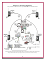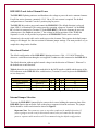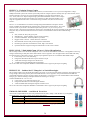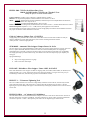
1
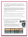
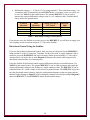
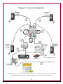
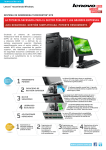
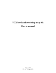
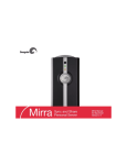
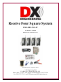
Receive Four Square System DXE-RFS-SYS-4P U.S. Patent No. 7,423,588 DXE-RFS-SYS-4P-INS Revision 1a DXE-RFS-SYS-4P Components Shown © DX Engineering 2012 P.O. Box 1491 ∙ Akron, OH 44309-1491 Phone: (800) 777-0703 ∙ Tech Support and International: (330) 572-3200 Fax: (330) 572-3279 ∙ E-mail: [email protected] Table of Contents Introduction System Overview Features Additional Parts Required Example of Array Performance Site Selection Proximity to Transmit Antennas Topographical Considerations Site Selection in Relation to Noise Sources Ground System Lightning Protection Sizing the Array Four Square Layout System Operational Overview Installation Active Antenna Elements Active Antenna Feedlines Delay Lines Control and Power Connections Default Configuration 3 4 4 5 5 7 7 8 8 9 9 10 11 12 12 13 14 14 16 18 Default Jumper Configuration Settings Diagram 1 - Default Configuration Optimizing the Array Front-to-Rear (Null) Optimizing Operation Normal Receive Four Square Operation Receive Four Square Troubleshooting 19 20 21 21 21 22 22 Appendix A - Alternate Configurations Supplying Power Using the Feedline Directional Control Using the Feedline Diagram 2 - Alternate Configuration Diagram 3 - Alternate Configuration DXE-RFS-2 and Active Element Power Directional Control Internal Jumper Selection Default Jumper Configuration 27 27 28 29 30 31 31 31 32 Optional Items Technical Support and Warranty 33 36 Figures Figure 1 - Site Selection Clear Distance Figure 2 - Layout of the DXE-RFS-SYS-4P Four Square System Figure 3 - Active Element L1MF Jumper Locations Figure 4 - Array Diagonal Dimension Figure 5 - Jumper Locations showing Default Settings 7 11 13 15 19 Tables Table 1 - Array Safety Distance Minimums at 1500 watts Table 2 - Array Side Lengths Table 3 - Examples of DLY3 Required Length Table 4 - BCD Directional Control Matrix, “1” Equals +12 Vdc (Default) Table 5 - Differential Voltage Control Matrix 2 8 10 15 27 28 Introduction DXE-RFS-SYS-4P - Complete Receive Four Square Array Package for Normal Spacing or Close Spacing to Transmit Antennas Complete Receive Four Square Array package for Normal or Close Spacing to Transmit Antenna W8JI design Operates from 100 kHz to 30 MHz Excellent directivity in a small space for better signal-to noise ratio Switchable in four 90 degree spaced directions Reduced susceptibility to high angle signals compared to EWE, Flag, Pennant, or K9AY arrays Low current DC powered control console allows system operation without AC power mains DXE-RFS-SYS-4P (U.S. Patent No. 7,423,588) is a complete Receive Four Square Array Package which includes: (1) DXE-ARAV3-4P Package of four Active Receive Vertical Antennas w/ Internal Antenna Disconnect Relays (1) DXE-EC-4 Four Position BCD Control Console (1) DXE-RFS-2 Receiving Four Array Controller (1) DXE-TVSU-1A Time Variable Sequence Unit (1) DXE-F6-1000 CATV F-6 Style Coaxial cable, 75 Ω, F6 Flooded for Direct Burial, 1000' Spool (1) DXE-CPT-659 CATV F-6, RG-6 and RG-59 Coaxial Cable Stripper, Includes 1 Replacement Blade (25) DXE-SNS6-25 Snap-N-Seal 75 Ω Coaxial cable Connectors for CATV F-6 Cable (1) DXE-SNS-CT1 Crimp Tool for Snap-N-Seal 75 Ω Coaxial cable Connectors 3 System Overview The DXE-RFS-SYS-4P is an advanced four square receiving system that uses four symmetrically spaced elements to provide switching for a 4-direction receiving antenna system. This unique system uses time delay phasing rather than the single band phase shifting used in traditional four squares. When used with active receive elements, this time delay phasing scheme provides the correct phase relationship across a wide frequency range producing useful front-to-rear ratio (F/R) response over octaves of bandwidth. This system uses directionally-optimized time delays to produce wider and deeper rear nulls. Wide null areas and a narrow main lobe greatly reduce noise and undesirable signals. The system is more reliable than a conventional transmitting four square system in receiving applications. Most transmitting four squares use large, exposed open-frame relays which can become contaminated or corroded. This system uses sealed relays; contact size is optimized for receiving applications. Features Advantages of the DXE-RFS-SYS-4P Receive Four Square Antenna System over other receiving arrays include: Seamless stainless steel RFS-2 enclosure, for enhanced weather resistance Reduced susceptibility to high angle signals compared to EWE, Flag, Pennant, and K9AY antennas Excellent directivity in a small space for better signal-to-noise ratio Switching of four 90 degree spaced directions Directivity over a very wide frequency range using DX Engineering’s Active Receive Antennas Requires less space than a Beverage antenna. Active elements need only a minimal ground system Easier to deploy and maintain than a four direction Beverage antenna system Using active elements, system allows close proximity to transmit antennas using transmit/receive sequencer Enhanced relay contact reliability Low current DC powered control console allows system operation without AC power mains This manual will describe the DXE-RFS-SYS-4P total system package in detail. The DXE-RFS-SYS-4P is a sophisticated system that has critical control voltage and three delay line connections. Failure to make quality feedline or delay line connections might result in an array that does not work or performs poorly. 4 Additional Parts Required, Not Supplied with the DXE-RFS-SYS-4P Four Conductor Power and Control Cable for RFS-2 Four conductor cable (3 plus ground), 22 gauge minimum is required. Economically priced COM-CW-4 is a four conductor control wire which may be used. Ground Rods (5/8" x 4 feet) for the Active Receive Vertical elements and the RFS-2 unit. Mounting pipe for the DXE-RFS-2. The DXE-RFS-2 unit has been pre-drilled to accommodate up to a 2 inch OD pipe using an appropriate clamp. If pipe mounting is desired, the optional DXECAVS-1P V-Bolt Saddle clamp for pipe from 3/4" to 1-3/4" inches OD is recommended, or DXESSVC-2P Stainless Steel V-Bolt Saddle Clamp for 1" to 2" OD pipe. The controller can also be mounted on a sturdy wooden post, but provision for grounding the DXE-RFS-2 unit must be made. Example of Array Performance Dedicated receive antennas have better signal-to-noise ratios. Directing the antenna away from noise sources or toward the desired signal path is the primary benefit. Antenna gain is a secondary advantage. As frequency increases, the fixed array size becomes electrically larger in terms of wavelength. The increased electrical spacing produces higher sensitivity (average gain) even though front-to-rear ratio only changes slightly. On the low bands, once the receiving system limits on external noise, antenna directivity (F/R) is the only thing that affects the signal-to-noise ratio. An average Beverage antenna exhibits about -6 dB gain. You would need two reversible Beverage systems to obtain 4-direction selectivity and you still would be limited to one or two bands. The DXE-RFS-SYS-4P system occupies less space, is much easier to install, is less conspicuous and operates over a wider frequency range with similar or better performance. A test array, constructed at DX Engineering using the DXE-ARAV3 Active Elements and a side length of 35 feet, showed excellent performance across a wide frequency range. This side length is optimal for 40m, according to Table 2. The array worked from 3 MHz to 15 MHz. As shown on the following page, the patterns stay clean with good directivity and front-to-rear performance. The elevation angle is 15 degrees for all patterns. Amplification is required below 3 MHz. Note: The DXE-RFS Receiving system must be separated from transmitting or other antennas and structures (particularly metal) by at least 1/2 wavelength. Less separation may cause significant pattern distortion and the introduction of reradiated noise and signals into the system. This becomes apparent as reduced front-to-rear directivity in one or more directions or a higher noise level. In a different test array with 50 ft side lengths, optimum performance occurred between 3 and 4 MHz. Performance on 7 MHz was also excellent. Amplification was used below 2 MHz. The highest usable frequency was 10 MHz. This array also produced usable F/R ratios down to the lower end of the AM broadcast band (600 kHz). 5 Increasing the array size increases its sensitivity on the lower frequencies, sliding the performance curve toward the low frequencies and potentially eliminating the need for amplification. 6 Site Selection Site selection is important. The DXE-RFS-SYS-4P system can be positioned as close as 1/10 wavelength to transmitting antennas. The DXE-ARAV3 Active Elements are bypassed to ground when power is turned off. A programmable sequencer, such as the DXE-TVSU-1A is required, and included with the DXE-RFS-SYS-4P, for close spacing requirements. Significant pattern distortion or coupling may result from close spacing. To prevent pattern degradation, reception of re-radiated electrical noise or other interference, separation of 1/2 wavelength (at the lowest operating frequency) is ideal. See Figure 1. The goal is to do the best you can by balancing all the factors. 1/10 wavelength is the minimum distance to any transmitting antenna from the Four Square perimeter, greater than 1/2 wavelength is the minimum distance that will limit coupling to other antennas and the introduction of broadband re-radiated noise and signals. Figure 1 - Site Selection Clear Distance Proximity to Transmitting Antennas The DXE-ARAV3-4P active elements and your transmitting antenna need only minimal physical separation to maintain safe power levels when the DXE-TVSU-1A sequencer is used. With 1500 watts output and a unity gain (0 dB) antenna, the closest active element can be 1/10 wavelength from the transmitting antenna at the lowest transmitting frequency. Doubling the protection distance quadruples safe power levels. See Table 1. 7 For example, transmitting legal-limit power output (1500 watts) into an ideal four square transmitting antenna produces about 6,000 watts ERP (6 dB gain). Because of the increased radiated power level, nearly 1/2 wavelength minimum spacing between the transmitting and receiving antenna arrays is required, even when using the DXE-TVSU-1A Time Variable Sequencer Unit to remove power from the active receive antennas used in the receive four square array. Table 1 indicates minimum safe distances for the sequenced active array from transmitting antennas with 0 dB, 3 dB and 6 dB gain (ERP) using a 1500 watt transmitter. Your actual system may vary according to location and proximity to various objects. Band Unity (0 dB) Gain 3 dB Gain (2x) 6 dB Gain (4x) 160m (1.8 MHz) 55 ft 110 ft 220 ft 80m (3.5 MHz) 28 ft 56 ft 112 ft 40m (7.0 MHz) 15 ft 30 ft 60 ft Table 1 - Array Safety Distance Minimums at 1500 watts For any DX Engineering Receive Four Square, using the DXE-TVSU-1A Time Variable Sequencer Unit to sequence Active antenna power will ensure that transmitted energy will not cause damage to the receive system. Topographical Considerations Flat land is best. Erecting the receiving array on sloped land or steep hills may degrade performance. To avoid pattern degradation, antenna elements must have reasonably similar elevations. It's recommended the ground height difference between any element in the array be less than 10% of the array diameter. For example, a 60 foot diameter array should be within six feet of level. Every effort should be taken to make the elements symmetrical. Elements should all be identical in construction and grounding, and should be mounted above any standing water line but as close to the ground as possible. In general, the system will not be affected by trees or foliage as long as the foliage does not contact the element. Ideally, in important receiving directions, there should be a clear electrical path for at least 1 wavelength. The site should allow a ground system to be evenly distributed around the antennas, if one is required. Site Selection in Relation to Noise Sources Because the array is directional across its corners, use this example as a guide: If you have a noise source and if your primary listening area is northeast, locate the array northeast of the dominant noise source. This ensures the array is looking away from the source of noise when beaming in the primary listening direction. The second-best location for the array is when the noise source is as far as possible from either side of the array. If you look at patterns, the ideal location for the array is one that places undesired noise in a deep null area. If your location doesn’t have the usual noise sources (power lines, electric fences, etc.), locate the array so that your transmitting antennas and buildings are off the back or side of the receiving array. 8 Noise that limits the ability to hear a weak signal on the lower bands is generally a mixture of local ground wave and ionosphere propagated noise sources. Some installations suffer from a dominant noise source located close to the antennas. Noise level differences between urban and rural locations can be more than 30 dB during the daytime on 160 meters. Nighttime can bring a dramatic increase in the overall noise level as noise propagates via the ionosphere from multiple distant sources. Since the noise is external to the antenna, directivity can reduce noise intensity. Consider these things about noise sources: If noise is not evenly distributed, performance will depend on the gain difference between the desired signal direction (azimuth and elevation) and average gain in the direction of noise. If noise predominantly arrives from the direction and angle of desired signals (assuming polarization of signals and noise are the same) there will be no improvement in the signal-tonoise ratio. If the noise originates in the near-field of the antenna, everything becomes unpredictable. This is a good case for placing receiving antennas as far from noise sources (such as power lines) as possible. Ground System The ARAV3-4P Active Elements work well with just a single copper ground rod placed as close as possible to the mounting pipe. The mounting pipe can be used as the system ground if the pipe is an adequate ground. It is recommended that a 3/4" or larger rigid copper water pipe, although conventional copper coated steel rods may also work. Depending on soil conductivity, you can expect better performance with multiple ground rods spaced a few feet apart. Increasing ground rod depth beyond 5 ft rarely improves RF grounding because skin effect in the soil prevents current from flowing deep in the soil. Avoid ground rods less than 5/8" OD. A good ground system improves the array performance and enhances lightning survivability. It is important that each ground system be the same for each active antenna in the array. You can test ground quality by listening to a steady local signal. Attach 15 ft of wire laid in a straight line (away from the coaxial feedline) to the initial 4 ft to 6 ft ground rod. If you observe a change in signal or noise level, you need to improve the ground. A second rod spaced a few feet away from the first one may correct the problem or 10 to 12 ground radials, each 15 ft long, should provide a sufficient ground system for most soil conditions. If a good ground cannot be established, use an optional DXE-RFCC-1 Receive Feedline Current Choke that will further decouple the feedline from the antenna and reduce common mode current and associated noise from the feedline. Lightning Protection While amateur radio installations rarely suffer damage from lightning, the best protection is to disconnect electrical devices during storms. The key to lightning survival is to properly ground feedlines and equipment and to maintain the integrity of shield connections. A proper installation improves lightning protection and enhances weak signal receiving performance. 9 Consult lightning protection and station grounding information in the ARRL handbooks, or by referring to the NEC (National Electric Code). The DX Engineering website also has technical and product information listed under “Lightning Protection and Grounding.” Use lightning surge protectors for the coaxial cable feedline and control lines. Sizing the Array When using active elements, the array side length can be as small as 1/10 wavelength and up to about 1/2 wavelength on the highest frequency to be used. Sizes below 1/10 wavelength result in unusable array sensitivity in the most desired bands. Making side lengths larger than 1/2 wavelength on the highest frequency will split the main lobe and cause pattern and front-to-back degradation. Determine the size of the array by considering the availability of appropriate space, frequency coverage desired and the near proximity to undesirable noise sources, transmitting antennas and other structures. If there are no space constraints, follow the array side length recommendations in Table 2 for excellent performance. Side lengths longer than the optimal lengths shown will move the peak sensitivity of the array toward the lower frequency. For example, if you are most interested in 160m performance with occasional use on 80m, make the side lengths longer than the optimal 98 feet shown for 160m and 80m. This will improve 160m performance, reduce sensitivity on 80m somewhat, but less than sizing the array exactly for 160m. Band 160 80 40 160, 80 80, 40 160, 80, 40 Optimal Side Min. Side Length in Ft Length in Ft 1.83 135 54 3.60 70 28 7.10 35 14 1.83, 3.60 98 40 3.60, 7.10 50 20 1.83, 3.60, 7.10 70 28 Table 2 - Array Side Lengths Freq - MHz Max. Side Length in Ft 270 140 70 192 98 137 If you have limited space, a carefully installed and amplified DXE-RFS can be used on multiple bands with very small side lengths. At smaller side lengths, careful construction using precise measurements is critical. On a fixed-size array, as frequency is decreased, the array signal output decreases along with array sensitivity. Eventually the received ambient noise signal level will decrease to a point where it is below your receiver’s noise floor. This comes from two effects: Elements become electrically shorter, reducing element sensitivity Element spacing becomes smaller in electrical degrees, reducing array sensitivity Side lengths at 1/10 wavelength on 40m would only be 14 ft. Although usable, amplification would be required. In addition, the construction of a very small array is extremely critical. Side lengths must be perfectly symmetrical. The delay lines must be directly measured for electrical length and cut to exact lengths. The ground system must be effective. Even at this small spacing, the array will have useful front-to-rear performance and directivity! 10 Four Square Layout The array antenna elements should be arranged in a square, use Table 2 for guidance in choosing the best combination of frequency coverage and side length dimensions. The diagonal corners of the square should point in the most desirable receiving directions. Element 1 is the default forward element, Element 3 is the rear or null element. Performance of the RFS-2 can noticeably decrease if structures radiating even small amounts of noise or signals are within 1-wavelength of the array Measure side-to-side and then corner-to-corner to ensure the element locations are square. Normally the RFS-2 phasing unit is installed near the center of the four array elements, above any standing water, with the connector side facing down. The placement of the RFS-2 unit is not critical, however, the feedlines to each of the active elements must be equal in length. If you mount the RFS-2 on a wood post, it should be grounded to a separate ground rod. Figure 2 - Layout of the DXE-RFS-SYS-4P Four Square System 11 System Operational Overview The DXE-RFS-SYS-4P system is comprised of the DXE-EC-4 BCD Control Console and the DXE-RFS-2 Control Unit. These units interconnect and work together using factory default settings. The DXE-EC-4 BCD Control Console supplies the nominal +12 Vdc operational voltage as well as the +12 Vdc BCD control voltage. The operational voltage powers the DXE-RFS-2 Control Unit which subsequently powers the active receive elements. The BCD switching voltages cause the DXE-RFS-2 to change the receiving direction of the array. The DXE-EC-4 Control Console is configured by default to output the BCD control voltages needed by the DXE-RFS-2. The default direction for the array (toward Element 1) is selected when LED 1 on the DXE-EC-4 is illuminated. When positions 2 to 4 are selected on the EC-4, the array switches directions. Refer to Diagram 1 for default connection details. The DXE-RFS-2 distributes the operating power to the active elements through the individual element feedlines. The active elements do not work without power. Cutting power to the DXE-RFS-2 also cuts power to the active elements which causes the DXE-AVA-2 to ground the vertical element. Operating with the DXE-TVSU-1A Sequencer (inserted into the EC-4 "C" to the RFS-2 "C" terminal) makes this power switching function automatically. An alternate configuration (refer to Appendix A) which uses the feedline coaxial cable for either the operational power or the directional control voltages, can be used. This configuration requires internal jumper changes in the DXE-RFS-2, along with additional hardware to couple the proper voltage to the feedline. For directional control through the feedline, the DXE-RFS-2 requires +12 Vdc, ─12 Vdc and 12 Vac. The DXE-FVC-1 Voltage Coupler can be used to supply these voltages. In any alternate configuration, do not use coaxial cable or other conductor for more than one simultaneous use. Refer to Diagram 2 for connection details of one of several alternate configurations. The only reason for using an alternate configuration is to make use of existing 2 or 3 conductor control cable. Otherwise inexpensive four conductor control cable (COM-CW-4) and the default configuration is recommended. Installation The DXE-RFS-2 Control Unit can be mounted to a galvanized pipe driven into the ground. The DXE-RFS-2 unit has been pre-drilled to accommodate up to a 2 inch OD pipe using an appropriate clamp. If pipe mounting is desired, the optional DXE-CAVS-1P V-Bolt Saddle clamp for pipe from 3/4" to 1-3/4" inches OD is recommended, or DXE-SSVC-2P Stainless Steel V-Bolt Saddle Clamp for 1" to 2" OD pipe. The controller can also be mounted on a sturdy wooden post, but provision for grounding the DXE-RFS-2 unit must be made. Note: UMI-81343 Never-Seez or DXE-NSBT8 12 Anti-Seize should be used on all clamps, bolts and stainless steel threaded hardware to prevent galling and to ensure proper tightening. The DXE-RFS-2 is designed to be used with the DX Engineering Active Vertical Antennas. It can also be used with passive elements. The user manual included with the active elements has instructions for assembly and installation. As noted in that manual, the active elements should be installed as close to the ground as possible but above any standing water or snow line. Ground the ANT– (negative) terminal to an adequate ground. Active Antenna Elements If you are planning to use the array on 160m, a jumper in the active antenna matching units should be changed. Placing a jumper on L1MF will peak the array sensitivity response for use on 160m, with little effect on 80m, when the recommended array side lengths in Table 2 are used. When doing this the sensitivity for the AM broadcast band will be reduced. All four active elements in the array must have identical jumper settings. For access to the jumpers in the active matching units, remove the 2 screws on each side of the case and remove the bottom. The circuit board and jumper headers will be visible, as shown in Figure 3. By default, there are no jumpers across any pins. Place a jumper across L1MF. Do not jumper any other positions. See the Active Antenna User Manual for more information about additional peak response jumper settings. Figure 3 - Active Element L1MF Jumper Locations Please read the manuals for the DXE-ARAV3 Active Elements and DXE-EC-4 Controller so you understand their operation before proceeding. Station Feedline, Active Antenna Feedline and Delay Lines The weakest link in an antenna system, such as the DXE-RFS-SYS-4P, is often the coaxial cable connections. All connections must be high quality and weather tight to prevent contamination and corrosion, which can cause the feedline impedance to change. This can affect the signal-to-noise ratio and the directivity of the array. In addition, the DXE-RFS-2 uses the shield as a ground return path for the active element power. Note: The total loop resistance of the ground path must be under 30 Ω for reliable operation. 13 If the resistance of the shield increases due to contamination, the active elements may not function properly. Any splices in the feedline should be high quality and entirely weather tight. Do not use splices in the delay line cables. The DXE-RFS-SYS-4P system has been designed to use only 75 Ω coaxial cable. Included with the DXE-RFS-SYS-4P package is high quality, flooded 75 Ω CATV F6 type coaxial cable. The DXE-F6-1000 flooded coaxial cable automatically seals small accidental cuts or lacerations in the jacket. Flooded coaxial cable also prevents shield contamination and can be direct-buried. Included with the DXE-RFS-SYS-4P package is the coaxial cable preparation tool, part number DXE-CPT-659, that readies the coaxial cable for connectors in one operation and comes with an extra cutting cartridge. To ensure weather tight connections, use DXE-SNS6-25 Snap-N-Seal compression style connectors are also included. DXE-SNS6-25 contains 25 Snap-N-Seal connectors, enough for the entire array plus some spares. The Snap-N-Seal connectors cannot be installed with normal crimping tools or pliers, so you also receive the installation tool DXE-SNSCT1, from DX Engineering with the DXE-RFS-SYS-4P package for proper connector installation. Active Antenna Feedlines Use 75 Ω coaxial cable from each antenna element to the DXE-RFS-2. The four feedlines from the DXE-RFS-2 phasing unit to the active elements can be any length needed to accommodate the size of the array, but must all be the same length, velocity factor and type. Note the orientation and numbering of the elements by using Figure 2. Be sure the appropriate antenna element is connected to the proper ANT connector on the phasing unit. The default (zero control voltage) forward direction is towards Element 1. Element 3 is the rear or null direction. Delay Lines The DXE-RFS-2 uses a time delay system, not a traditional phasing system. Delay line lengths are dictated by array dimensions rather than operating frequency. This results in phase being correct for a rearward null at any frequency. This system is especially effective when used with DX Engineering ARAV3 active vertical elements. User-supplied passive elements can also provide exceptional performance for single or dual band operation where high dynamic range is required. The DXE-RFS-2 phasing unit has three sets of delay line connections marked DLY1, DLY2 and DLY3. Each of these connection pairs will have a specific length of coaxial cable acting as a jumper between the two connectors. Jumper electrical length is critical. Careful measurements and the use of 75 Ω coaxial cable (included in this package system) with a known Velocity Factor (VF) is very important. If you are not using the included DXE-F6-1000 coaxial cable, keep in mind that solid Teflon® or polyethylene dielectric coaxial cable has a VF of approximately 0.66. Foamed coaxial cable cables typically range anywhere between 0.75 and 0.90 VF, depending on the ratio of air-to-dielectric material in the cable core. If you do not know the VF of the coaxial cable you are using, you must 14 directly measure the electrical length of the coaxial cable you have or obtain cable with a known VF. The included DX Engineering DXE-F6-1000 75 Ω coaxial cable has a nominal VF of 0.85. For best performance, the coaxial cable for the delay lines should be from the same batch or spool. The first step is to determine the required electrical length of DLY3. This is based on the cornerto-corner or diagonal distance between two diagonal corner elements of the square forming the array. You can directly measure this distance, or it can be calculated by multiplying the side length of the array by 1.4142. The electrical length of delay line DLY3 should be slightly shorter than the actual physical distance between the two diagonal corners of the array. An electrical length 95% of the physical distance works well (diagonal distance times 0.95). Table 3 shows these calculations for three common side lengths. Diagonal Factored 0.95 DLY3 Physical Length Side Length in Physical Length Electrical Length in Feet (0.85 VF) Feet in Feet in Feet 135 (160m) 190.9 181.4 154.2 98 (160m & 80m) 138.6 131.7 111.9 70 (80m) 99.0 94.0 79.9 Table 3 - Examples of DLY3 Required Length After calculating the required electrical length, you must include the VF of the coaxial cable being used when determining the correct physical length of DLY3. Multiply the factored electrical length by the VF. The result is the correct physical length for DLY3. See Figure 4 and the sidebar for an example. Note: These calculations are in feet, not feet and inches. To find the physical length of DLY3, calculate the diagonal length of the array by either directly measuring the diagonal or by multiplying the array side length by 1.4142. DLY3 will be significantly shorter than the actual physical length. The diagonal length is first multiplied by 0.95. This gives the factored electrical length for DLY3. Next, multiply the DLY3 electrical length by the VF of the delay line coaxial cable. The result is the correct physical length for DLY3. Figure 4 - Array Diagonal Dimension 15 For Example: An array with 90 foot side spacing, the diagonal length is 127.3 feet. The 0.95 factored physical length for DLY3 electrical length is 120.9 ft. Multiply 120.9 ft. by 0.85 (the VF of DX Engineering 75 Ω coaxial cable). The correct physical length for DLY3 is 102.77 feet, or 102 feet 9 inches. Delay lines DLY1 and DLY2 must be half the length of DLY3. Make DLY1 and DLY2 as close to half the physical length of DLY3 as possible. To avoid performance degradation due to inconsistent coaxial cable construction, all the delay line coaxial cable should be cut from the same spool. Delay line cables can be neatly coiled in a 1-1/2 ft diameter coil. Support the weight of the cables by taping or securing them to the support pole or mast rather than allowing them to hang from the connectors. It is important to use 75 Ω feedline to the operating position from the DXE-RFS-2. Do not use amplifiers, combiners, filters or splitters that are not optimized for 75 Ω systems. Control and Power Connections If you have the DXE-RFS-SYS-4P system, with the DXE-EC-4 Control Console, no other equipment is needed for powering the DXE-RFS-SYS-4P, the active elements or controlling the receive direction of the DXE-RFS-SYS-4P. The DXE-RFS-SYS-4P has been factory-set to work with the DXE-EC-4 using four conductor control cable such as COM-CW4. J12 is the 5-terminal connector plug on the front panel of the DXE-RFS-2. It is labeled G A B C G. The DXE-RFS-2 uses a two part green connector and the top part can be removed by pulling it straight off. This will allow easier wire replacement or servicing as needed. When pushing the connector back in place, ensure you press straight inward. 16 The DXE-EC4 uses an internal terminal plug labeled “G 1 2 3”. DXE-EC-4 G 1 2 3 to to to to DXE-RFS-2 G A B C Direct Wire connections between the DXE-EC-4 and DXE-RFS-2 For systems that have 1/2-wavelength or greater spacing between the receive four square array and any transmitting antenna, The TVSU-1A may not be needed. The wiring diagram above shows wiring between the DXE-EC-4 and the DXE-RFS-2. If you are using the DXE-TVSU-1A, the wiring connections are shown in Diagram 1 - Default Configuration. Control lines (usually BCD ) can normally use good quality CAT5e cable (4 twisted pairs of 24 AWG wire) for runs up to 1000 feet. Typical DX Engineering BCD control lines requirements are +12 VDC at 25 milliamps. Depending on the number of control lines needed (usually 3 or 4) you can double up the twisted pairs of CAT5e cable, or use control wire that is at least 22 AWG, allowing runs up to 1500 feet. If you use a cable with more conductors, it is a good idea to tie the unused conductors to ground. For longer runs of control cable, use a line loss calculator to ensure you supply the proper control levels needed. 17 Approximate BCD Control Line Lengths. Minimum Copper Wire Gage (AWG) 24 22 20 Length 1,000 feet 1,500 feet 2,000 feet Active antenna circuitry needs a good voltage supply to operate properly. When supplying power to an active antenna, you want to have +12 VDC, 60 milliamps at each active (under load). CAT5e cable is not recommended when making long runs to power an active antenna since the line loss in CAT5e cable may not supply the proper operational voltages required for active antennas. Depending on the required length of your power wire, you will want to use a line loss calculator (voltage drop with various wire gages) to ensure your power supply (normally +13.6 well filtered DC) will supply a minimum of +12 VDC, 60 milliamps at each active antenna (under load). A DX Engineering 4 Square or 8 Circle will require approximately 250 milliamps (only 4 actives are powered at any one time). When calculating line length, take into consideration the total number of active antennas being powered at any one time in your line length calculations. Approximate Active Antenna Power Line Lengths (4 active antennas on at any one time). Minimum Copper Wire Gage (AWG) 18 16 12 10 Length 300 Feet 500 feet 1,200 feet 2,000 feet Default Configuration The DXE-RFS-SYS-4P default configuration, as shown in Diagram 1, uses terminals A & B for the BCD directional control interface and terminal C for operational and active element power. The DXE-EC-4 provides the operational power as well as the 2-bit BCD interface used for directional control. A user-supplied 4-conductor cable is needed to connect the DXE-RFS-2 and the DXE-EC4 with the included DXE-TVSU-1A Time Variable Sequencer Unit switching the active antenna power conductor. 18 The switch positions on the DXE-EC-4 control the directivity of the received signal in the DXE-RFSSYS-4P. As shown in the diagram to the right, position one favors the NE direction, position 2 favors the SE direction, position 3 favors the SW direction and position 4 favors the NW direction when the array is positioned as shown. Default Jumper Configuration Settings Figure 5 shows the default jumper settings for the DXE-RFS-2. For JMP1 & JMP2 the center and top pins of both are shorted. For JMP3 & JMP4, the center and bottom pins of both are shorted. Figure 5 - Jumper Locations showing Default Settings JMP1 Selects Power Voltage Source: Coax or J12 - Shown in default position, voltage from J12 JMP2 Selects Direction Voltage Source: Coax or J12 - Shown in default position, voltage from J12 JMP3 and JMP4 Select Directional Voltage Configuration, either Differential or BCD. Both Jumpers must be set the same. - Shown in default position for BCD 19 Diagram 1 - Default Configuration for the DXE-RFS-SYS-4P Shown with optional items. Power connections not shown for clarity. 20 Optimizing the Array To determine if the antenna system output level is the limiting factor, tune the receiver to the lowest band at the quietest operating time. This is usually when propagation is poor but some signals are heard. Disconnect the antenna and set the receiver to the narrowest selectivity you expect to use. Receiver noise power is directly proportional to receiver bandwidth (going from 2.5 kHz selectivity to 250 Hz selectivity reduces noise by 10 dB). Connecting the antenna should result in a noticeable increase in noise. If so, the array signal level is sufficient and further optimization or amplification may not be needed. If the array is used on 160m or below, the Active Antenna internal jumper should be set as shown in the Installation Section of this manual. If the array still lacks sensitivity on the lower bands, then a preamplifier with high dynamic range should be used to compensate for the low signal level. Using a preamplifier when sufficient signal is already present may result in amplification of the noise along with the signal. It is always best to use the least gain possible. Depending on conditions, a preamplifier can cause receiver overload; this may require an attenuator or bypassing the preamplifier. The DXE-RPA-1 HF Preamplifier has better dynamic range than most receivers and can be used to compensate for the decrease in array signal output. The DXE-RPA-1 preamplifier is automatically bypassed when power is removed. Front-to-Rear (Null) Optimizing The DXE-RFS-2 is factory adjusted to the correct settings for most coaxial cables. In some cases, the null depth may need to be adjusted to compensate for inaccurate delay line lengths. To adjust the null depth, tune to a strong steady signal off the back of the antenna’s selected direction and adjust R4 and R8 for the deepest null (weakest signal off the back). Use Figure 5 to locate R4 and R8 near the center of the circuit board. Operation When using the DXE-RFS-2, positions 1 though 4 on the EC-4 BCD Control Box will phase the appropriate active vertical elements to give you excellent receiving capabilities. The front to back signal to noise ratio of the active vertical elements in the four phase array allow you to not only enhance the desired received signal, but also to decrease an unwanted receive signal by selecting a position that will drastically reduce or eliminate it. 21 Normal Receive Four Square Operation When the Receive Four Square system is functioning properly, low or medium power daytime AM Broadcast ground wave signals should be alternately attenuated or improved with directional switching. However, strong sky wave signals arriving at high angles of propagation will show very little signal level change as different directions are selected on the Receive Four Square. Although some low band signals may be received at very low levels, they are heard more easily due to far less noise received by the non-resonant array. If necessary, the use the DXE-RPA-1, Receiver Preamplifier - an in-shack pre-amplifier with exceptionally low-noise and high dynamic range characteristics. The DXE-RPA-1 will enhance the intelligibility of the weak DX signals, without adding the noise that plagues many of the pre-amps that are built into modern transceivers. The Receive Four Square array pattern is designed to enhance forward low angle signals, and reject rearward and high angle signals. The Receive Four Square system provides superior signal-to-noise results that allow you to hear signals that are impossible to copy on much noisier transmit antennas, for greatly improved weak signal DX operations. Receive Four Square Troubleshooting There are several possible causes for a malfunction of a DX Engineering Receive Four Square System. Testing the system is not difficult and can be completed in an hour or so. Separate circuits for directional switching, Active Vertical Antenna power, and antenna phasing can each be affected by a variety of cabling, connection and or component problems. If you are troubleshooting a new system or using a replacement RFS-2 unit, check that the internal jumpers are set correctly for your system control and voltage configuration. Here are the most common causes of Receive Four Square malfunction, especially in a system that was previously functioning properly: 22 Start 80% of all Receive Four Square malfunctions are caused by A, B or C Check Internal Jumpers A Broken/Shorted Conductors B Center Conductors slipped C Shorted/Open conductors due to water D Zapped by lightning pulse or RF overload. Animals, Chewed, Punctured, Stretched or Broken. Green Connector may have broken a wire or is tightened against insulation - not bare wire. Check all F connector center conductor wires. They may have pulled inward. Check feedlines and control cable. Make sure units are at least 1/2 wavelength, on the lowest frequency, away from any transmit antenna. May want to use optional DXETVSU-1 Time Variable Sequence Unit for AVA-2 units. E RFS-1 damaged due to lightning. F Damaged by animals/insects. Rare, but can happen Animals have been known to relieve them selves on the units and the urine will corrode and damage electronics. Insects getting inside units and shorting out electronics. A) Broken and/or shorted conductors due to animal, weather or other damage, including chewed, punctured, stretched and broken control and power lines and/or feedlines for the system and each antenna. Also, screws in the green removable connectors can inadvertently be tightened onto the insulation of control or power conductors. B) Regressed center conductors in the feedlines causing disengagement from the female center capture pin of the F connector. This can happen in delay lines as well as in antenna or main feedline connections. Many times a compression F connector that seems to have a long enough center conductor when it was made, has regressed to the point that it is not long enough to make proper contact. A properly installed F connector should have the center conductor protruding 1/4 inch beyond the shell when viewed from the side. Check all F connectors! 23 C) Shorted or opened conductors caused by water migration into a control line or a feedline. Over 80% of all Receive Four Square malfunctions have been caused by the above system problems. A thorough inspection and subsequent testing of each control cable, RF cable, and their respective connections, will uncover the cause of most RFS troubles. Here are a few other causes for RFS malfunction: D) One or more burned out Active Vertical Antenna units model AVA-2 or AVA-1, due to lightning pulse or high power RF overload. One-half wavelength on the lowest frequency is the minimum distance between the Active antennas and any transmit antennas. If that distance is less and high power is used, then the Time Variable Sequence Unit, model DXE-TVSU-1A must be used to interrupt power to the AVA-2 units. E) Damaged RFS-2 unit due to lightning. This has been reported only a couple of times and is not very likely. F) Active units that were damaged by animals. Once we received actives damaged by an animal that relieved themselves on the antenna whips and AVA units, as if they were “trees”. The above items are the most common failure points in the system that need to be checked. If necessary, the following further troubleshooting procedure may assist in finding the malfunction. Receive Four Square Control Troubleshooting Procedure 1) Test the DXE-EC-4 BCD Control Console unit, which should be connected only to the control lines of the Receive Four Square System. When the EC-4 is connected to the control cable, do all of the selected switch position LEDs light normally? 2) When rotating the Control Console switch from position 1, 2, 3 and 4, if all LEDs light normally, measure BCD output voltages. Normally, +12 for the EC4 is output on the green connector terminals located inside the unit. Connections 1, 2 and 3, reference to the ground pin G as shown below. The selected position will supply the BCD logic voltage as shown in the chart below. Forward Direction EC-4 Switch Position BCD Terminal EC-4 LED Illuminated 1 2 3 Element 1 (Default) 1 #1 0 0 1 Element 2 2 #2 1 0 1 Element 3 3 #3 0 1 1 Element 4 4 #4 1 1 1 BCD Directional Control Matrix, “1” Equals +12 Vdc (Default) 24 The numbered terminals of the 4-pin green connector correspond to the numbers in the table above, with voltage measured as referenced to the G ground terminal. 3) If the voltages are not normal, less than +10 to 18 Vdc, with the control line connected, then disconnect the control line and retest the Control Console. If voltages that were not correct, are now okay, that indicates a short in the control line or a problem in or beyond the RFS-2 Receive Four Square relay unit. 4) If the EC-4 has only a couple LEDs lit with the control cable disconnected, then it may have sustained lightning pulse damage and will need to be repaired or replaced. A new DXE-EC-4 is available from DX Engineering. Continue troubleshooting the array control with a good EC-4 or by using a 1A fused power source. 5) Determine if the control line is intact by resistance or voltage testing each conductor for shorts with the far end of the control cable disconnected from the RFS-2 unit. 6) With a good EC-4 or other power source connected, measure A, B and C control conductor voltages at the RFS relay unit with the control cable connected, and again at the end of the control cable that is disconnected from the RFS relay unit. If measured voltages are not between +10 to 18 Vdc on the selected line, a resistive, short or open circuit problem exists in the control line or in the RFS relay unit or antenna feedlines. Normal voltages on the connected control line will cause relays to switch inside the RFS unit. If switching voltages are correct, lack of system directivity or gaps in reception may be due to antenna, feedline or delay line issues. 7) Test the Active Antennas by feeding a voltage on the tested control line A and/or B conductor(s) to select one direction of RFS unit operation. Simultaneously feed normal operating voltage on the tested conductor that powers the Active Verticals for reception. If a low value fuse blows, then a short circuit may be isolated by disconnecting antennas and reconnecting them one at a time. If no fuses have blown and connected voltages stay near the nominal +12 Vdc levels, then: 8) Test for active operating voltage at the end of each antenna feedline. If all are good, proceed. If not, repair feedlines and/or connectors. If voltage is present on the power line to the RFS relay unit, but is not measured at the end of good feedlines, inspect inside RFS-2 relay unit to determine if there is an obvious reason that Active Vertical Antenna power is not making it out the antenna ports. A bad connection outside of the RFS relay unit is usually the problem, and rarely has a component failure inside the RFS relay unit been discovered. If the system previously functioned properly, then the internal jumpers would have been previously set in their proper positions for your system configuration. If you are troubleshooting a new system or using a replacement unit, check that the internal jumpers in the RFS-2 unit are set correctly for your system control and voltage configuration. 25 Proper Receive Four Square phasing requires that each Active Vertical Antenna, and its respective equal length feedline, actually provides the same signal level to the RFS unit. Use a steady, non-fading ground wave signal from a low or medium power daytime AM Broadcast station that is over 10 miles away, on a frequency high in the band, or another constant signal source on 160 or 80 meters, well away from the array, to test that each Active Vertical receives the same signal level. Do not use sky wave or night signals for these signal level tests. 9) Test reception of each Active Vertical Antenna by connecting each antenna feedline, one at a time, to an activated port on the RFS-2. This assumes that a good port has been identified and is functioning properly. Normal reception must be confirmed from each antenna. If any antenna is not providing the proper RF signal level, move the AVA unit to a known good feedline position to rule out the possibility that a bad feedline is attenuating the RF. If one or more Active Receive Verticals produce a low or no signal, then the AVA unit at the base of that antenna may not be receiving power. Retest for DC power at the antenna end of that feedline. If + 10 to 18 Vdc is found, then the Active unit may need to be serviced or replaced. New DXEAVA-2 units are available separately by calling DX Engineering. 10) If all Active Verticals tested provide the same signal level, then change switching voltages to activate the other ports, one at a time, and test each RFS unit port, using one of the good antennas, testing for the same level of reception. If one or more ports is dead or has diminished reception, there may be a problem in a delay line or in the RFS unit. 11) Using tested or replaced delay lines and connectors, if one or more ports is dead or has diminished reception, the RFS unit may require service or replacement. At this point, the problem in your system should have been identified. If you need additional assistance from DX Engineering, feel free to call or write. Detailed discussions of system function, connections, and troubleshooting is best handled by telephone, Monday through Friday, 8:30 am to 4:30 pm Eastern Time, at 330-572-3200. 26 Appendix A Alternate Configurations An alternate configuration which uses the feedline coaxial cable for either the operational power or the directional control voltages, but not simultaneously, can be used. This configuration requires internal jumper changes in the DXE-RFS-2, along with additional hardware to couple the proper voltage to the feedline. For directional control through the feedline, the DXE-RFS-2 requires +12 Vdc, ─12 Vdc and 12 Vac. The DXE-FVC-1 Voltage Coupler can be used to supply these voltages. In any alternate configuration, do not use coaxial cable or other conductor for more than one simultaneous use. Refer to Diagram 2 for connection details of one of several alternate configurations. The only reason for using an alternate configuration is to make use of existing 2 or 3 conductor control cable. Otherwise inexpensive four conductor control cable (COM-CW-4) and the default configuration is recommended. Any alternate configuration requires changing the internal jumpers from their default settings. Be very careful about changing the default jumper settings. You must not jumper the DXERFS-2 so that power and directional control are done on the same conductor. This will damage the RFS-2 or the ARAV-3 active elements and is not covered under warranty. Supplying Power Using the Feedline If you use the feedline to supply operational power, then directional control for the RFS-2 must be done using the J12 connector. There are two ways to do directional control through J12 when using the coaxial cable for power: 2 bit BCD style control voltage using terminals 1 & 2. See Table 4. This requires at least a 2 conductor cable. Economically priced COM-CW-4 is a 4 conductor Shielded Control Wire which may be used. The feedline shield can be used for the ground return provided it is grounded at the common power source. Forward Direction Rear Direction A B C EC-4 LED Illuminated Element 1 (Default) Element 3 (Default) #1 0 0 1 Element 2 Element 4 #2 1 0 1 Element 3 Element 1 #3 0 1 1 Element 4 Element 2 #4 1 1 1 Table 4 - BCD Directional Control Matrix, “1” Equals +12 Vdc (Default) 27 Differential voltages (+/–12 Vdc & 12 Vac) using terminal C. This can be done using a 1 or 2 conductor cable. Economically priced COM-CW-4 is a 4 conductor control wire which may be used. See Table 5 for the control matrix. The optional DXE-FVC-1 can be used to generate the required differential voltages using a 1 or 2 conductor cable. Feedline shield can be used as the ground return. Forward Direction Element 1 Element 2 Element 3 Element 4 Rear Voltage on Coax or Direction Direction J12 Term C Shift Element 3 None 0° Element 4 +12 Vdc 90° Element 1 -12 Vdc 180° Element 2 12 Vac 270° Table 5 - Differential Voltage Control Matrix If you choose to use the feedline to provide power to the DXE-RFS-2, you will have to supply your own coupling circuit to insert the required +12 Vdc on the feedline. Directional Control Using the Feedline If you use the feedline for directional control, then you must provide power for the DXE-RFS-2 using terminal C of the J12 connector. Terminals A & B are not used. A single conductor cable is needed to power the DXE-RFS-2 and active elements. Station power (nominal +12 Vdc) can be used provided a 1A in-line fuse is used. Diagram 2 illustrates the coaxial cable being used for directional control and the use of station power. Using the feedline for directional control requires differential voltages to switch directions. Use Table 5 for the control matrix. The optional DXE-FVC-1 can be used to generate and couple the required differential voltages to the feedline or a single conductor cable. The DXE-FVC-1 can be controlled with a EC-4 with a simple switch closure-to-ground scheme. The DXE-FVC-1 provides only the directional control voltages. Study the configuration diagrams on the next pages and the Internal Jumper Settings in Figure 5 before making any changes to the default settings. Diagram 2 shows the DXE-FVC-1 and the DXE-EC-4 used for directional control. 28 Diagram 2 - Alternate Configuration All Element feedlines, delay lines and station feedlines must be 75 Ω coaxial cable. RFS-2 internal jumper changes are required. Element feedlines can be any length, but must be equal. Power lines not shown for clarity. 29 Diagram 3 - Alternate Configuration Using a manual switch connected to the optional DXE-FVC-1 for directional control All Element feedlines, delay lines and station feedlines must be 75 Ω coaxial cable. Requires RFS-2 internal jumper changes. Element feedlines can be any length, but must be equal. Power lines not shown for clarity. 30 DXE-RFS-2 and Active Element Power The DXE-RFS-2 phasing unit uses and distributes the voltage to power the active antenna elements. For all four active elements, a nominal +12-15 Vdc at 250 mA current is required. The default configuration uses Terminal C on the 5-position plug for power. The DXE-EC-4 is used to power and control the DXE-RFS-2. The default direction is selected when LED #1 is illuminated. This setting provides operating voltage on Terminal 3 of the DXEEC-4, which is connected to Terminal C on the DXE-RFS-2. (The active elements do not work without power.) See Table 4; note that “3” has voltage in all four positions. If the TVSU-1A Sequencer is used, it will provide keyed power to the DXE-RFS-2 for the active verticals. Alternatively, the coaxial cable can be used to power the elements. This requires the default jumper settings to be changed. See the next section for alternate jumper settings. You must provide a way to couple this voltage on the feedline. Directional Control The default configuration of the DXE-RFS-2 phasing unit uses a 2-bit, +12 Vdc BCD interface scheme to switch directions through a user-supplied 4 conductor cable connected to the DXE-EC-4. The default direction without applied control voltage is in the direction of Element 1. Element 3 is the default rear or null direction. Table 4 shows the array direction, the truth table for the BCD interface (A&B) and the status of the LED indicators on the DXE-EC-4 for each direction. (Terminal C is used to power the DXE-RFS-2 so it is always on.) Forward Direction Rear Direction A B C EC-4 LED Illuminated Element 1 (Default) Element 3 (Default) #1 0 0 1 Element 2 Element 4 #2 1 0 1 Element 3 Element 1 #3 0 1 1 Element 4 Element 2 #4 1 1 1 Table 4 - BCD Directional Control Matrix, “1” Equals +12 Vdc (Default) Internal Jumper Selection To access the DXE-RFS-2 jumper blocks, remove the 6 screws holding the connector plate of the DXE-RFS-2 unit to the enclosure. Pull on the plate to separate it from the enclosure. The jumper blocks should be visible and oriented as shown in Figure 5. Important Note: You cannot use coax or any other conductor for multiple functions. If you are going to use the coax for directional control, then you cannot use the coax for power-a separate cable must be used. We recommend using the default configuration. 31 Default Jumper Configuration Settings Figure 5 shows the default jumper settings for the DXE-RFS-2. For JMP1 & JMP2 the center and top pins of both are shorted. For JMP3 & JMP4, the center and bottom pins of both are shorted. Figure 5 - Jumper Locations showing Default Settings JMP1 Selects Power Voltage Source: Coax or J12 - Shown in default position, voltage from J12 JMP2 Selects Direction Voltage Source: Coax or J12 - Shown in default position, voltage from J12 JMP3 and JMP4 Select Directional Voltage Configuration, either Differential or BCD. Both Jumpers must be set the same. - Shown in default position for BCD 32 Optional Items DXE-RPA-1 - Receiver Preamplifier, 0.3-35 MHz This is the best HF low noise amplifier available. The RPA-1 is optimized for 0.3-35 MHz operating range. The push-pull amplifier design and robust components enable it to withstand high signal levels and operate when you need it most. The dynamic range of the RPA-1 is better than most receivers. The RPA-1 is suitable for indoor or outdoor installation, with the option of being powered through the coaxial feed. The metal housing provides shielding and improved lifespan. The unit uses RCA type phono jack and CATV F connector for the input and output connections, and has a relay that automatically bypasses the amplifier when dc power is removed. Benefits: Push-pull operation eliminates harmonic distortion High quiescent current increases ability to handle strong signals without distortion or overload Meticulous craftsmanship and durable components provide superior dynamic range RCA type phono jack and type F connector ease installation Simplified switching - automatic bypass eliminates gain when dc power is off 10-18 Vdc power using power connector or through the coaxial cable 10-18 Vdc through coaxial cable enables remote operation at antenna DXE-RFCC-1 - Receive Feedline Current Choke, 50 to 75 Ω 300 kHz to 30 MHz If you wish to reduce feedline radiation and improve reception, a Feedline Current Choke is recommended if your SWR is already low. Adding a DX Engineering Feedline Current Choke at the point where the feedline exits the area of the antenna will substantially reduce unwanted feedline radiation or reception without the need for improved station grounding. The advantages of using an FCC: Prevents unwanted RFI by eliminating feedline current and radiation All power goes to the antenna, improving efficiency Reduces noise or unwanted signals picked-up by the feedline Overcome a less than optimal ground system The DX Engineering RFCC-1 receive feedline common-mode choke is the most effective solution to common-mode noise or unwanted signal ingress available to date. The DX Engineering RFCC provides thousands of ohms isolation between the input and output coaxial shield connections while passing desired signals, including dc or low frequency ac control signals. The RFCC has extremely high isolation impedance which effectively blocks common-mode noise or unwanted signals, even in the presence of very poor grounding. Low noise receive antennas are traditionally located away from electrical wiring and other noise sources. Unfortunately, noise and other unwanted signals have a direct path to your low-noise antenna through the feedline shield connections between the station equipment and antenna. Unwanted signals can also energize the outside of the feedline shield, and this undesired signal energy can be conducted directly to the receiving antenna. This can reduce antenna directivity. Unless you have a perfect zero-resistance RF ground at the antenna, some of the common-mode noise or unwanted signals from the feedline shield will make it into the antenna. The RFCC is effective from 300 kHz to 30 MHz. It comes with standard CATV type “F” female connectors, although it can be used in any 50 to 75 Ω receiving system. The RFCC is a passive device, therefore requires no power to operate. 33 DXE-FVC-1 - Feedpoint Voltage Coupler The FVC-1 provides an interface for standard control switches, such as the DXE-CC-8A or your own arrangement to voltagemultiplexed antenna systems. This interface system will provide the voltages required to remotely select up to four antennas (or four directions) through receiving or low power transmitting feedlines. It provides fuse-protected 0V, +12 Vdc, -12 Vdc, and 12 Vac. output voltages through a panel mounted feedline connector. These voltages can be used to provide four-direction switching of an antenna array either through the feedline or on a single wire supplemental control line. Control is done using a standard 1 of 4, BCD or switch closure interface. The FVC-1 is recommended for use with the DX Engineering RFS-2P Remote Four-Square Antenna System , the RBS-1 Reversible Beverage Antenna System , and the RLS-2 Transfer Switch . The CC-8A Control Console can provide the 1 of 4 and BCD input used by the FVC-1 or you can use your own switch. The FVC-1 also has two LED indicators, red and green, which indicate the presence and polarity of the output control voltage being used. They are directional indicators that can be read at a convenient distance and can aid in troubleshooting. Features Safe, external 12V heavy duty power pack. Metal Housing – superior shielding, rugged, and easy mounting Convenient installation– mounts anywhere in your shack Rugged Control Connector – reliable solder-less connections Internal thermal reset fuse- full protection against accidental shorts Flexible logic input- BCD or standard one-of-four, high or low actuated Operation indicators- bright red and green LED indicators can be seen at a distance DXE-CAVS-1P - V-Bolt Saddle Clamp, 1/2 in. to 1-3/4 in. OD Applications This V-Clamp is made in one size that fits tubing from 1/2 to 1-3/4'' OD as used in antenna construction. The supplied V-bolt is long enough to attach tubing to thick plates and is made with anti-corrosive properties. The cast rippled surface of the saddle will clamp the tubing securely to a flat surface; however, for high-torque applications please use our standard U-Bolt Saddle Clamps. Used to clamp 1/2 to 1-3/4'' (OD) tubing Designed for attachments that don't require resistance to torque V-bolt made from high-strength 18-8* stainless steel V-saddle cast from 535 aluminum with rippled surface The use of an Anti-Seize compound is HIGHLY recommended to achieve proper torque and prevent galling. DXE-SSVC-2P - Stainless Steel V-Clamp for 1 to 2 inch OD steel pipe This V-Clamp is made in one size that fits Steel tubing or pipe from 1 to 2'' OD as used in antenna construction. The supplied V-bolt is long enough to attach tubing to thick plates and is made with anti-corrosive properties. The special Stainless Steel saddle has serrated teeth will clamp to the pipe securely by biting into the surface. For this reason, it is not recommended for softer aluminum tubing or pipe. Ideal for fastening a radial plate and antenna mounting to a steel pipe. V-Bolt thread dimensions: 5/16"-18 x 2.0" Used to clamp 1 to 2'' (OD) steel tubing or pipe Designed for attachment to round steel support members V-bolt and saddle made from high-strength 18-8* stainless steel The use of an Anti-Seize compound is HIGHLY recommended to achieve proper torque and prevent galling. UMI-81343, DXE-NSBT8 - Anti-Seize & Never-Seez An Anti-seize compound MUST be used on any Stainless Steel nuts, bolts, clamps or other hardware to prevent galling and thread seizure. Any of these products can be used for this purpose. *UMI-81343 Anti-Seize, 1 oz. Squeeze Tube *UMI-81464 Anti-Seize, 8.5 oz. Aerosol Can *DXE-NSBT8 Never-Seez, 8 oz. Brush Top *DXE-NMBT8 Never-Seez, 8 oz. Brush Top, Marine Grade * These products are limited to domestic UPS Ground shipping only 34 DXE-F6-1000 - 75 Ω F-6 Style Direct Bury Coax, 1000 ft. Spool Hi Quality, 75 Ω F6 type "Flooded" Coax Sold by the spool, or as Custom Cable Assemblies Center Conductor: 18 AWG Copper-Clad Steel , Nominal Diameter: 0.040 in. Dielectric: Gas Expanded Polyethylene, Nominal Diameter Over Dielectric: 0.180 in. Shield: 1st Shield: Aluminum-Polypropylene-Aluminum, Laminated Tape with overlap Bonded to the Dielectric, Nominal Diameter Over Tape: 0.187 in. 2nd Shield: 34 AWG Aluminum Braid Wire, 60% Coverage Jacket: PE (Flooded for Underground), Nominal Diameter Over Jacket: 0.272 in. , Nominal Jacket Thickness: 0.030 in. Electrical Properties: Impedance: 75.0 +/- 3.0 Ωs, Velocity of Propagation: 85.0% Nominal We recommend the use of Snap-N-Seal connectors to ensure a high quality and weather resistant feedline connection. The proper tool must be used to install these connectors. Cable, 4 Conductor, Sold per Foot - COM-CW4 A high quality, PVC jacketed 4-wire control cable, COM-CW4 consists of 4 #20 AWG conductors. It may be used in a multitude of control cable applications, such as remote switching and antenna rotators. Sold by the foot - order the length you need. SUM-900031 - Automatic Wire Stripper/Crimper/Cutter, 24-10 Ga. Our wire stripper uses a spring-loaded design to make quick work of wires ranging from 24 to 10 gauge. Just insert the wire, squeeze the handle, and listen for the click. That’s the sound of another perfect wire stripping job performed in about 2 seconds- a fraction of the time it takes your pocket knife to do the same job. An adjustable wire length guide helps you make uniform strips, and a built-in wire cutter and crimper helps you complete your wiring job. Spring-loaded design Strips wires ranging from 24 to 10 gauge built-in wire cutter and crimper KLE-11055 - Klein-Kurve Wire Stripper / Cutter 11055, 18-22 AWG Klein Tools Klein-Kurve wire strippers are ideal for stripping solid (10-18 AWG) and stranded (12-20 AWG) wire cleanly and easily. The 7 1/8 in. strippers also have precise shear-type blades to cut copper wire nicely, easy-toread markings on both sides, and extra-soft grips and curved handles for comfort. DXE-CIT-1 - F Connector Tightening Tool The CIT-1 installs and removes F connectors in high density and hard to reach locations, and is the only tool that works with bent coaxial cable. Only finger force is required. Provides enough leverage to achieve a 30 in/lb tightening force by hand. Helps insure proper connections thereby reducing the potential of loose connector related service calls. DXE-PSW-12D1A - AC Adapter 12 Vdc/1000 mA The DXE-PSW-12D1A is an AC Wall Transformer Adapter to furnish 12 Volts DC at 1000 mA from 120 Vac 60 Hz input, fused output. It features a standard 2.1 mm plug connection for 12 Vdc. Outer connection is GROUND Center Pin is input for +12 VDC. Ideal separate power source for DX Engineering EC-4 BCD Switch 35 UMI-82180 - Permatex Black RTV Sealant, Non-Acetic - 3.3 oz Tube, Black DX Engineering Approved RTV Sealant - We have all used RTV to seal water out of things, right? Have you ever sealed a piece of electronic gear with it -- then opened it some time later to find that it had still managed to become corroded inside? Guess what? It's not the rain that corroded it - It's the RTV! Normal RTV gives off acetic acid when it cures. That's the vinegar smell. The acetic acid causes the corrosion. DX Engineering has located a Neutral Cure RTV made right here in Ohio that is non-corrosive and is safe for sealing those baluns and other electronic gear that are going to be out in the weather. Applies just like "normal" RTV, dries in one hour and cures in 24 hours at 70 degrees F. And it doesn't smell like vinegar! 3.3 oz. Tube Black *This part is classified hazardous and is limited to domestic UPS Ground shipping only Technical Support If you have questions about this product, or if you experience difficulties during the installation, contact DX Engineering at (330) 572-3200. You can also e-mail us at: [email protected] For best service, please take a few minutes to review this manual before you call. Warranty All products manufactured by DX Engineering are warranted to be free from defects in material and workmanship for a period of one (1) year from date of shipment. DX Engineering’s sole obligation under these warranties shall be to issue credit, repair or replace any item or part thereof which is proved to be other than as warranted; no allowance shall be made for any labor charges of Buyer for replacement of parts, adjustment or repairs, or any other work, unless such charges are authorized in advance by DX Engineering. If DX Engineering’s products are claimed to be defective in material or workmanship, DX Engineering shall, upon prompt notice thereof, issue shipping instructions for return to DX Engineering (transportation-charges prepaid by Buyer). Every such claim for breach of these warranties shall be deemed to be waived by Buyer unless made in writing. The above warranties shall not extend to any products or parts thereof which have been subjected to any misuse or neglect, damaged by accident, rendered defective by reason of improper installation, damaged from severe weather including floods, or abnormal environmental conditions such as prolonged exposure to corrosives or power surges, or by the performance of repairs or alterations outside of our plant, and shall not apply to any goods or parts thereof furnished by Buyer or acquired from others at Buyer’s specifications. In addition, DX Engineering’s warranties do not extend to other equipment and parts manufactured by others except to the extent of the original manufacturer’s warranty to DX Engineering. The obligations under the foregoing warranties are limited to the precise terms thereof. These warranties provide exclusive remedies, expressly in lieu of all other remedies including claims for special or consequential damages. SELLER NEITHER MAKES NOR ASSUMES ANY OTHER WARRANTY WHATSOEVER, WHETHER EXPRESS, STATUTORY, OR IMPLIED, INCLUDING WARRANTIES OF MERCHANTABILITY AND FITNESS, AND NO PERSON IS AUTHORIZED TO ASSUME FOR DX ENGINEERING ANY OBLIGATION OR LIABILITY NOT STRICTLY IN ACCORDANCE WITH THE FOREGOING. ©DX Engineering 2012 DX Engineering®, DXE®, Hot Rodz™, Maxi-Core™, THUNDERBOLT™, Antenna Designer™, Yagi Mechanical™, and Gorilla Grip® Stainless Steel Boom Clamps, are trademarks of PDS Electronics, Inc. No license to use or reproduce any of these trademarks or other trademarks is given or implied. All other brands and product names are the trademarks of their respective owners. Specifications subject to change without notice. 36