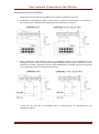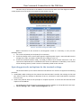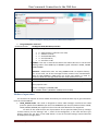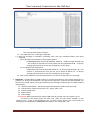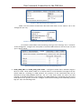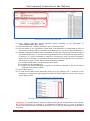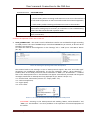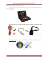
1
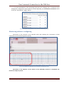
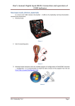
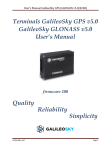
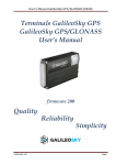
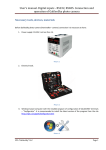
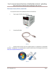
User’s manual. Connection to the CAN-bus Necessary tools, devices, materials To connect a GalileoSky terminal (hereinafter - terminal) to the vehicle CAN-bus (hereinafter vehicle) one should have: 1. Electrical tools. Picture 1 2. Set of connecting wires, connecting USB cable, cable of connection to the diagnostic socket OBD-II. Picture 2 3. Windows-based computer with the installed program of configuration of GALILEOSKY terminals – "Configurator". It is recommended to install the latest version of the program from the site http://7gis.ru/support/konfigurator.html Picture 3 SPA “GalileoSky” LLC Page 1 User’s manual. Connection to the CAN-bus 4. The measuring device – a multimeter. Picture 4 General information Industrial real-time CAN network is a network with a common communication environment and consists of units with their own clock generators, for example, dashboard or subsystem of definition of temperature in the vehicle (Pic. 5). Any unit of the CAN network sends a message over the network and each unit of the system decides whether this message concerns to it. To solve this task CAN has a hardware implementation of message filtering. CAN controllers are connected using the differential bus, which has two lines - CAN_H (Сan-High) and CAN_L (Can-Low), through which signals are transmitted. Picture 5. Standard scheme of the CAN bus The CAN-bus protocol is implemented in two versions: version А sets 11- bit identification of messages (i.e. there can be 2048 messages in the system), version B — 29- bit identification of messages (536 million messages). SPA “GalileoSky” LLC Page 2 User’s manual. Connection to the CAN-bus Connection to the CAN-bus Connection of the terminal to the CAN bus on a vehicle is possible in two ways: 1. connection to the diagnostic OBD-II socket, which is present on the majority of vehicles as a rule. Connection is carried out according to the scheme shown in Picture 6: Picture 6. The scheme of connection of the terminal to the diagnostic socket 2. direct connection to the CAN bus if there is no diagnostic socket or if the CAN lines are not brought to it, and if it does not contradict conditions of the warranty service. Connection is to be carried out as follows: dismantle the part of the dashboard, find twisted CAN pair and connect to it in accordance with the scheme of the Picture 7: Picture 7. The scheme of direct connection of the terminal to the CAN-bus ATTENTION! Use this way of connection only in extreme cases, we recommend to use contactless readers. SPA “GalileoSky” LLC Page 3 User’s manual. Connection to the CAN-bus The main way of connection to the CAN bus is the connection with use of the diagnostic OBD-II socket (appearance and contact pin assignments are shown in Pic. 8). Picture 8. The scheme of diagnostic OBD-II socket Before connection of the terminal to the diagnostic socket it is necessary to carry out the following actions: 1. use contacts 6 (CAN-H) and 14 (CAN-L) for connection; 2. check the voltage at the contacts with regard to negative power supply - CAN-H should have the voltage of 2,5-2,8 V, and CAN-L should have the voltage of 2,1-2,3 V; 3. check the resistance between CAN_L and CAN_H contacts when vehicles electronics is off. The resistance of about 60 Ohm is considered to be normal. At indication of 120 Ohm (in case of lack of the matching resistor) install a resistor of 120 Ohm parallel to the contacts. Operating protocols and options for the terminal settings The terminal allows you to receive data from the CAN bus of a vehicle if it supports the following protocols: 1. J1939 (FMS). When working via this protocol the terminal doesn't transfer the message to the CAN bus, doesn't make any changes to operation of the car, and doesn't send confirmations to packets from car units. 2. J1979. This protocol works on the principle of “request-response” it means that the terminal sends requests to the CAN bus. All configuration of the terminal to receive data from the CAN-bus can be produced in two ways: 1. On the “Settings” tab -> “CAN” of the Configurator (Pic. 9) SPA “GalileoSky” LLC Page 4 User’s manual. Connection to the CAN-bus Picture 9. Setting for receiving data from the CAN bus in the Configurator 2. using CanRegime command Command format CanRegime Mode,BaudRate,TimeOut Parameters Mode – operating mode: 0 – CAN interface is off and is not used; 1 – CAN bus scanner; 2 – standard FMS filter; 3 – user filter29 bit; 4 – user filter 11 bit BaudRate – bus rate. It must be the same as the vehicle bus rate. It can have the following values: from 10000 up to 500000. Typical valuations: 62500, 125000, 250000, 500000. Explanation Example TimeOut – measured in msec. For CAN_SCANER mode it is response latency. If it is too small, not all bus messages will be received. The recommended time for CAN_SCANER is 2000 msec. For all the rest modes it is time to receive at least one message otherwise the value will be set to zero. General CAN bus control. Example: Enable scanner for a 250000 b/sec bus with the message (answer) latency equal to 2 sec. Request: CanRegime 1,250000,2000 Reply: CANREG: Mode=1,BaudRate=250000,TimeOut=2000; Modes of operation The terminal can operate in several modes that allow you to find the best way to get information from the vehicle CAN bus: 1. J1939_SCANER mode. This mode is designed to receive CAN messages transferred via J1939 protocol. Speeds from 10000 bits per second to 500000 bits per second (standard values: 62500, 12500, 250000, 500000) are supported. The 11-bit and 29-bit identifiers are supported. For work in this mode choose one of parameters of bus speed and delay time (a message receive timeout) on the “Settings” tab -> “CAN” of the Configurator; in this case the filter type doesn't matter (Pic. 10). Press “Listen CAN” button. In case of successful settings received data will be displayed in the right panel. SPA “GalileoSky” LLC Page 5 User’s manual. Connection to the CAN-bus Picture 10. Configuring scanning of CAN-bus in the Configurator The scanning mode works as follows: 1.1. The «CAN. Start scan.» message is displayed; 1.2. CAN bus messages in identifiers ascending order with the established delay start being displayed; 29-bit identifiers are displayed in the following format: - ID=00000009 (8) 01 02 03 04 05 06 07 08, where ID – 29-bit message identifier; (8) – the number of received bytes from the bus; 01 02 03 04 05 06 07 08 – an 8-byte message (the lower byte on the left, the high byte on the right); 11- bit identifiers are displayed as: - ID=009 (8) 01 02 03 04 05 06 07 08, where ID – 11-bit message identifier; (8) – the number of received bytes from the bus; 01 02 03 04 05 06 07 08 – an 8-byte message (the lower byte on the left, the high byte on the right); 1.3. After all the identifiers have been displayed you can see the «CAN. End scan.» message. 2. FMS mode – standard filter of J1939 protocol. In case the manufacturer of the vehicle (generally it is producers of heavy-load equipment, the agricultural equipment) supports the FMS standard, the choice of this mode allows you to get and decrypt the messages conforming to the FMS standard automatically: 2.1. total fuel consumption – the amount of fuel the vehicle has used since it was made; 2.2. tank fuel level, measured in percent. 0% - empty. 100% - full; 2.3. coolant temperature; 2.4. engine speed; 2.5. total mileage. ATTENTION! Many manufacturers support FMS protocol partially or do not support it at all. For work in this mode choose the filter type “FMS” and bus speed “250000” on the “Settings” tab -> “CAN” of the Configurator (Pic. 11). Press “Apply” button. The second variant of setting: give the CanRegime 2,250000,2000 command on the “Commands” tab. SPA “GalileoSky” LLC Page 6 User’s manual. Connection to the CAN-bus Picture 11. FMS mode setting in the Configurator Make sure the terminal receives bus data and sends them to the “Device” tab in the Configurator (Pic. 12); Picture 12. The results of analysis of data from the CAN-bus via FMS standard To send the received data to the monitoring server go to the “Settings” tab -> “Protocol” of the Configurator, configure the main packet to transmit CAN bus data to the server (Pic. 13) and press “Apply” button; Picture 13. Selection of parameters to be sent to the monitoring server 3. J1939_USER_29bit and J1939_USER_11bit modes – configured custom filters, identifier length is 29-bit or 11-bit. These modes enable us to receive 29-bit or 11-bit identifiers messages from the vehicle CAN bus, according to J1939 protocol. The presence of the transmitted data can be determined using J1939_SCANER mode (Pic. 10). As a rule, these modes are used if the data received on the FMS standard are not enough or the FMS standard isn't supported, but data on the J1939 protocol are present at the bus. Configure received data binding to the GalileoSky protocol tags (Pic. 14) in the following order: SPA “GalileoSky” LLC Page 7 User’s manual. Connection to the CAN-bus Picture 14. Setting a custom filter J1939 mode 3.1. listen CAN-bus messages, having executed actions according to the description of "J1939_SCANER Mode" given above; 3.2. select the filter type “ J1939 custom filter, 29 (or 11)-bit identifiers”; 3.3. ask your dealer or car manufacturer which data in the identifiers are responsible for work of this or that unit of the vehicle. These data can be stored in one, two or four bytes in identifiers; 3.4. establish compliance between data in identifiers and one-byte, two-byte and four-byte tags of the GalileoSky protocol, i.e. if in the interesting identifier from all accepted data only one byte is necessary, it is more reasonable to compare a one-byte tag. From the useful information received on this identifier, it is possible to choose that part of bytes which have to be filled in tag contents by means of shift. Execute these operations as follows: 3.3.1. specify the identifier in the first column of the table; 3.3.2. choose the corresponding tag; 3.3.3. specify the shift visually using a mouse; the number transmitted to the server will be displayed in the column "Value". 3.5. press “Apply” button. 3.6. to send received data to the monitoring server go to the “Settings” tab -> “Protocol” of the Configurator, configure the main packet to transmit the chosen tags to the server (Pic. 15) and press “Apply” button; Picture 15. Selection of parameters to be sent to the monitoring server ATTENTION! It is possible that the diagnostic OBD-II socket may be connected not to the CAN-bus but to one of the units, for example, to a combination of devices (Pic. 5), and as a result the terminal can't listen the bus and receive identifiers. In this case you should give the ActiveCAN 1 command. SPA “GalileoSky” LLC Page 8 User’s manual. Connection to the CAN-bus Command format ActiveCAN OnOff Parameters OnOff – operating mode: 0 – passive mode: packets receiving confirmations are not sent to the CAN bus. It is a safe mode of operation. It does not interfere with the on-board equipment; 1 – active mode: packets receiving confirmations are sent to the CAN bus. Control of packets confirmation sending to the CAN bus. Confirmation sending may be necessary at connection to the troubleshooting socket if the data cannot be read in passive mode. Example Request: ActiveCAN 1 Reply: ACTIVECAN:1; Use this command only in the above situation and with care, because in this mode, the terminal emulates the operation of the units of the car! Explanation 4. J1979_SCANER mode – this mode is used to define data transfer rate and identifier length according to J1979 protocol. The rate of 250000 bits per second and 500000 bits per second, 11-bit and 29-bit identifiers are supported. To enable this mode in the Configurator: on the “Settings” tab -> “CAN” press “Test OBD II” button (Pic. 16): Picture 16. Selecting the operating mode under J1979 protocol The terminal sends a test message. In case of J1979 protocol support “Bus rate” and “Filter type” parameters are established automatically. As the last parameter “OBD II, 29-bit identifiers” – standard filter of the J1979 protocol for 29- bit identifiers or “OBD II, 11- bit identifiers” – standard filter of the J1979 protocol for 11- bit identifiers can appear. Automatically retrieved and decrypted messages transferred via J1979 protocol are displayed on the “Device” tab (Pic. 17): 4.1. tank fuel level, measured in percent. 0% - empty. 100% - full; 4.2. coolant temperature; 4.3. engine speed; 4.4. errors codes. Picture 17. The results of analysis of data from the CAN-bus via J1979 protocol ATTENTION! Scanning on the J1979 protocol and enabling “OBD II, 29-bit identifiers” and “OBD II, 11- bit identifiers” can cause problems in the operation of on-Board equipment of the vehicle. SPA “GalileoSky” LLC Page 9 User’s manual. Connection to the CAN-bus To send received data to the monitoring server go to the “Settings” tab -> “Protocol” of the Configurator, configure the main packet to transmit tags CAN_A1, CAN16BITR0-CAN16BITR4 to the server (Pic. 18) and press “Apply” button; Picture 18. Selection of parameters to be sent to the monitoring server Monitoring software configuring Connection of the terminal to the CAN-bus ends with checking the correctness of data transmission to the monitoring server (Pic.19): Picture 19. Displaying the indications in the program of monitoring server Connection of the CAN-bus of the vehicle to the GalileoSky terminal is completed; the terminal is ready to operate. SPA “GalileoSky” LLC Page 10