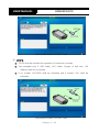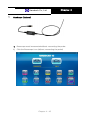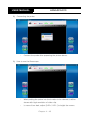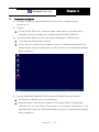
1
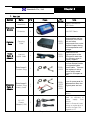
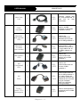
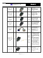
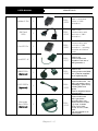
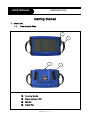
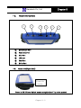
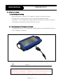
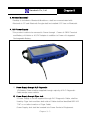
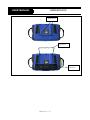
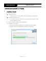
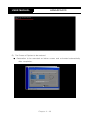
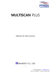
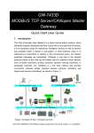
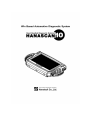
Chapter 1 Hanatech Co., Ltd. Chapter 1 Safety and Warranty Safety Instructions ------- 1-3 Safety Precautions ------- 1-4 Warranty Service ------- 1-6 Chapter 1 - 1 USER MANUAL HANASCAN10 Safety and Warranty About this Manual All rights reserved by Hanatech Co., Ltd., Gumi, Korea. The contents of this manual are the result of contributions by dozens of individuals all who have added their vital expertise and experience to the evolution of the contents of this manual. The information contained in this manual may contain printing errors and is subject to change without obligation to notify any person or organization according to product upgrade or modification. Hanatech shall not be liable for errors contained herein or for incidental or consequential damage in connection with the furnishing, performance, or use of this material. No part of this manual may be photocopied, reproduced, or translated to another language in any way without the prior written consent of Hanatech Co., Ltd. Using this Manual It is recommended that the user become familiar with the operating procedures, terminologies and information contained within this user’s manual. This will help to increase the user’s effectiveness with this equipment. Vehicle system familiarity While this equipment provides very powerful functions with extensive vehicle coverage, it cannot replace knowledge and skill. To get the most out of this equipment, a full understanding of vehicle systems is required. It is recommended that the equipment be used in conjunction with the original service manual for the vehicle being tested. The equipment is designed for use by trained service personnel and this manual assumes that the service technician who is going to use this equipment has a familiarity with vehicle electronic control systems, however, the latest service manuals and bulletins should always be referenced before using this equipment. Chapter 1 - 2 Hanatech Co., Ltd. Chapter 1 I. SAFETY INSTRUCITONS Thank you for purchasing HANASCAN 70 scanners. To get the maximum performance of the equipment, please carefully read this manual first, and keep it at hand. On delivery inspection When the equipment is delivered, a check should be made for any damaged or missing components. If the unit is damaged or fails to operate according to the specifications, contact your local distributor or the manufacturer, Hanatech Co., Ltd., Hana bldg., 80-1 Songjung-dong, Gumi-shi, Kyung-buk Republic of Korea 730-913. In the unlikely event the equipment requires shipping back to the manufacturer, please use the original packing material. Safety symbols The following symbols are used throughout this manual: DANGER This mark means that dangerous consequences may arise, with the possibility of death or serious injury to the user, if the machine is handled incorrectly. WARNING This mark means dangerous consequences may arise, with the possibility of somewhat serious injury to the user and or damage to the machine and facilities, if the equipment is handheld incorrectly. SYMBOL Description This symbol is affixed to locations on the equipment where the operator should consult corresponding topics in this manual (which are also marked with the symbol) before using relevant functions of the equipment. In the manual, this symbol indicates explanations that are particularly important that the user is expected to read the manual before using the equipment. This symbol represents DC (Direct Current) Chapter 1 - 3 USER MANUAL HANASCAN10 Safety guideline In order to ensure proper operation and satisfactory performance, observe the cautions listed below. DANGER This equipment is designed to comply with IEC61010-1 safety standards, and has been tested for safety prior to shipment. Excessive high voltage measurement or improper operation could result in personal injury, as well as damage to the equipment or the vehicle. Please read this manual carefully and be sure that you understand its contents before using the equipment. The manufacturer disclaims all responsibility for any accident except for that resulting due to defect in its product. WARNING For safety reasons, this equipment should not be used to measure circuits carrying more than 30Vrms or 42.4V peak. To avoid electrical accident that could result in injury or death, do not measure voltage in excess of these limitations. Maximum rated measurable voltage is 30Vrms or 42.4V peak. II. SAFETY PRECAUTIONS DANGER When an engine is running, keep the workshop area WELL VENTILATED or attach a building exhaust removal system to the engine exhaust system. Engines produce carbon monoxide, an odorless and poisonous gas that causes slower reaction time and may lead to serious injury or death. WARNING Brakes and wheel blocks Apply the hand brake and block the wheels before using the test equipment. It is highly recommended to block the wheels on front- Chapter 1 - 4 Chapter 1 Hanatech Co., Ltd. wheel drive vehicles because the hand brake does not hold the driving wheels. Drive Test Do not drive the vehicle and operate the test equipment at the same time. Any distraction may cause an accident. Have one person operate the test equipment while the other person drives the vehicle. Never place the test equipment in front of you when driving the vehicle because the test equipment may hit your body and cause serious injury when the air bag inflates. Do not try to test the SRS air bag system while driving the vehicle as unintended airbag inflation may result . Engine Compartment Maintain sufficient clearance between moving components or belts while using the test equipment in the engine compartment. Moving components and belts may catch loose clothing, test cables or a part of your body and cause damage or personal injury. Electrical Components Always turn the ignition key OFF when connecting or disconnecting electrical components unless otherwise instructed. Vehicle Battery equipments are designed to prevent damage from reverse polarity battery cable connection, however, it is always highly recommended to always ensure correct polarity terminal connection. Never lay the test equipment on vehicle battery. You may short the terminals and may cause damage to your body, the test equipment or the battery. To avoid damaging the test equipment or displaying false data, make sure the vehicle Chapter 1 - 5 USER MANUAL HANASCAN10 battery is fully charged and the connections to the electronic control module are clean and tight. The warning messages above and the safety messages contained hereinafter cover situations Hanatech is aware of. of the possible hazards. Hanatech cannot know, evaluate or advise you as to all You must make sure that any conditions or service procedures encountered do not jeopardize your personal safety. III. WARRANTY SERVICE Warranty Period In principle, HANASCAN 70 products are warranted to the consumer to be free of defects in material and workmanship for the period of 3 years after the date of purchase. If the product is found defective during this period, the product can be returned to Hanatech and will be repaired or replaced free of charge. Freight and repair Cost For the repair of head unit, Hanatech covers the freight cost for the service during one year from the date of purchase, and you can send the troubled unit to your local distributor without having to pay the freight cost. You should consult with your local distributor about the validity of remaining warranty period before sending the unit. For the remaining two years, you are liable for any international cost incurred. Repair or replacement will be provided free of charge. When the warranty period is expired after three years, the customer must pay the round trip freight and the repair or replacement cost. Upon delivery Hanatech inspects all the ordered product parts and components are included in the package before shipment, and includes the original copy of pre-shipment inspection report in the box. As soon as the product is delivered to you, please ensure everything you ordered is properly checked and included referring to the pre-shipment inspection report. If there is anything missing or damaged, you must notify the local distributor immediately within 3 working days from the delivery date for free of charge replacement of the parts. Chapter 1 - 6 Hanatech Co., Ltd. Chapter 1 In case of trouble If you encounter any malfunction or trouble with the equipment, please refer to the Trouble Shooting chapter in this manual. local distributor for assistance. If the problem cannot be solved, please contact your For early identification of a fault or error, your local distributor will require the following details: 1. Symptom of problem you are experiencing 2. Serial number of the head unit 3. Vehicle information: Which specific car were you testing when the problem occurred – Model name, Model year and system ID number if available (for Mitsubishi, Subaru and Suzuki only: Refer to Japanese car chapter for details) Warranty Void Even in the effective warranty period, if the problem is found to be caused by any of the followings, Hanatech charges the cost for round trip freight and actual cost for the service to the customer, and the shipment back to the customer will be suspended until the customer’s payment is duly made 1. Evidence of improper use or application of the product ignoring the cautions and warnings stipulated in the user’s manual 2. Intentional damage or modifications to the product or user’s attempt to repair without proper authorization 3. Any damage caused by Force Majeure including war and natural disaster 4. Loss of time, inconvenience and other consequential damage or loss Warranty void seal In addition to the above mentioned warranty void conditions, warranty service is not provided in case the warranty void seal is broken or removed. If you remove the head unit safety boot, you will see a yellow round sticker covering one of the screw holes in the back. Please be careful not to break this seal and never try to open the head unit without direct authorization from the manufacturer. Bought in other countries Only the products properly supplied by the contracted authorized local distributors are Chapter 1 - 7 USER MANUAL HANASCAN10 recognizable for free of charge warranty service. Any equipment bought outside the contracted national territory of your local distributor will be charged for service. FCC RF INTERFERENCE STATEMENT Note This equipment has been tested and found to comply with the limits for a Class B digital device, pursuant to Part 15 of the FCC Rules. These limits are designed to provide reasonable protection against harmful interference in a residential installation. The equipment generates, uses and can radiate radio frequency energy and, if not installed and used in accordance with the instructions, may cause harmful interference to radio communications. However, there is no guarantee that interference will not occur in a particular installation. If this equipment does not cause harmful interference to radio or television reception which can be determined by turning the equipment off and on, the user is encouraged to try to correct the interference by one or more of the following measures; - Reorient or relocate the receiving antenna - Increase the separation between the equipment and receiver - Connect the equipment into an outlet on a circuit different from that to which the receiver is connected Caution Changes or modification not expressly approved by the party responsible for compliance could void the user’s authority to operate the equipment. Chapter 1 - 8 Hanatech Co., Ltd. Chapter 1 THIS DEVICE COMPLIES WITH PART 15 OF THE FCC RULES. OPERATION IS SUBJECT TO THE FOLLOWING TWO CONDITIONS; (1) THIS DEVICE MAY NOT CAUSE HARMFUL INTERFERENCE. AND (2) THIS DEVICE MUST ACCEPT ANY INTERFERENCE RECEIVED INCLUDING INTERFERENCE THAT MAY CAUSE UNDESIRED OPERATION. Chapter 1 - 9 Hanatech Co., Ltd. Chapter 2 Chapter 2 Specification and Parts Specification ------- 2-2 Part List ------- 2-3 Chapter 2 - 1 USER MANUAL HANASCAN10 Specification and Parts 1. Specification 1) Hardware & Protocol Item Specification Main Controller Interface Power ETC Intel Atom N270 1.6GHz USB 2.0 2EA LAN Intel 82574L 10/100/1000 Mbit Video Out Up to QXGA(2048X1536) Wireless Bluetooth 2.1 + EDR & Wi-Fi Indicator Status LED x 2EA Standard 15VDC, 0.9A Min-Max range 12~32VDC Battery Li-ion 5200mAh echargeable OBD-I Supported PC Interface 802.11 b,g,n Power.Charge/Full ISO 9141-2 ISO14230(KWP) Protocol OBD-II J1850(PWM & VPW) CAN 2.0A/2.0B (High Speed, Middle Speed, Single Wire) 2) Environmental Operating Temperature : 0 ~ 85℃ Max Relative Humidity : 85% and less 3) Dimension & Weight Horizontal .................................................................. 312mm Vertical 198mm .................................................................... Thickness Weight ............................................................... 60mm ................................................................... 2.1Kg All specifications are subject to change without notice for the purpose of product and quality improvement Chapter 2 - 2 Chapter 2 Hanatech Co., Ltd. 2. Part List Section Diagnostic Module Carrying Case Power Cable & Adaptor Qn’ty Head Unit 1 Impact Resistance ABS Resin Protector 1 Soft PVC Resin 1 30030003 Provides convenient transportation and the protection of the head unit and other components from outer physical impact during the transportation and storage 30000004 Supplies power to the head unit from the cigarette lighter socket. LED lights on both ends turn ON when power is properly supplied 1 30080003 For the replacement of the fuse located inside the cigarette lighter power cable. You can also replace it with a fuse of which rated current is 2 Ampere or less. 1 1 30080003 30000005 Carrying Case Cigarette Lighter Cable Extra fuses & Contact Plug Diagnose Cable & Adaptor Extra fuses & Contact Plug Battery Cable Image Part Number Name 1 Note A set of spare parts for replacement when the original parts are lost Power cable 2 – Vehicle Battery AC-DC Power Adaptor(12V) Used for difficulty of Power supply from Vehicle Used for External Power during on registration of Product through F/W upgrade or PC 1 Chapter 2 - 3 USER MANUAL Main Data Link OBD2 Standard Mitsubishi and Hyundai 12Pin Mitsubishi 12+16pin dual headed GM Daewoo 12Pin KIA (Old Model) 6Pin HANASCAN10 1 30010001 Connects vehicle side DLC and HANASCAN 70 head unit for data transmission 1 30010010 Used for all OBD generation 2 and EOBD compatible vehicles. 1 30010001 Used for the communication with Mitsubishi and Hyundai cars of OBD generation 1 1 30010030 Used for the communication with Mitsubishi cars with both of 12-pin OBD1 and 16pin OBD2 adapters onboard. 1 30010002 Used for the communication with Daewoo cars of OBD generation 1. 1 30010003 Used for the communication with old Kia cars of OBD generation 1. KIA 20Pin 1 30010004 Used for the communication with Kia cars of OBD generation 1. DTC read & erase and data stream functions are available for the cars with this type of adapter. Refer to the following warning message. Toyota / Lexus 17Pin Rectangular 1 30010011 Used for the diagnosis of Toyota and Lexus of OBD generation 1. Chapter 2 - 4 Chapter 2 Hanatech Co., Ltd. Mazda 17Pin Adapter Toyota/Lexus 17Pin Semicircular Nissan/ Samsung 14Pin Ssangyong 14Pin Ssangyong 20Pin Honda 3 Pin Adapter and 2 Pin Jump Wire Subaru 9Pin 1 30010013 Used for the communication with Mazda cars of OBD generation 1. 1 30010012 Also used for the diagnosis of Toyota and Lexus of OBD generation 1. 30010006 Used for the Communication with Nissan cars of OBD generation 1 and all Samsung passenger cars. 30010007 Used for old Ssangyong cars of OBD generation 1. Vehicle side DLC is located in the engine room 1 1 30010005 1 3-pin: 30010014, 1X1 2-pin wire: 30010023 30010022 1 Chapter 2 - 5 Used for Ssangyong cars of OBD generation 1. Vehicle side DLC is located in the engine compartment. Refer to the warning above. 3-pin adapter is used for the diagnosis of Honda cars of OBD generation 1 that support DTC read and erase as well as data stream. Older Honda cars have 2pin DLC that supports DTC read only. The jump wire is used for these older cars to bridge the 2pin DLC terminals. The vehicle side DLC is generally located under the dashboard or the glove box. Used for the communication with Subaru cars of OBD generation 1. USER MANUAL Holden 6 Pin GM Opel 10Pin Ford 20 Pin Ford EEC-IV BMW 20Pin (Optional) HANASCAN10 1 30010023 Used for Australian Holden of OBD generation 1. 1 30010019 Used for the communication with Opel cars of OBD generation 1. 1 30010020 Used for the communication with Ford cars of OBD generation 1, including Australian and British Fords. 1 30010017 Used for the communication with Australian Ford cars of OBD generation 1, 1 30010016 Used for the communication with BMW cars. (Can be supplied as an optional part) VAG 2X2Pin (Optional) 30010029 1 Used for the communication with the OBD1 generation cars of Volkswagen / Audi Group including SEAT and Skoda. (Can be supplied as an optional part) Mercedes Benz 38Pin (Optional) 30010015 1 Chapter 2 - 6 Used for the communication with OBD1 generation Mercedes Benz cars . Applied with the models e.g) C202, CLK208, E210, E124, S140, SL129, SLK170, G463, G461. (Can be supplied as an optional part) Chapter 2 Hanatech Co., Ltd. Mercedes Benz 4Pin (Optional) Bore Scope 30010009 1 Used for the communication with early 1990’s or earlier model year Mercedes Benz cars e.g) C201, E124, S126, SL107, G463 (Red: Battery +, Gray: K Line,, Yellow : Ignition check, Black: Ground) (Can be supplied as an optional part) Internal such as invisible Intake Air Manifold etc. shall be observed by naked eyes as multipurpose borescope. (Can be supplied as an optional part) 1 Chapter 2 - 7 Hanatech Co., Ltd. Chapter 3 Chapter 3 Getting Started Head Unit ------- 3-2 DLC Cable ------- 3-4 Power Supply ------- 3-5 Indicator LED ------- 3-5 Chapter 3- 1 USER MANUAL HANASCAN10 Getting Started 1. Head Unit 1-1. Front & back Side 2 1 4 ①. Carrying Handle ②. Status Indicator LED ③. Stander ④. Touch Pen Chapter 3 - 2 3 Chapter 3 Hanatech Co., Ltd. 1-2. Head Unit(Top Side) 1 ①. Bore Scope Port ②. Video Out Port ③. DLC Port ④. LAN port ⑤. USB Port ⑥. DC in Port 1-3. 2 3 4 5 6 Head Unit(Right Side) Power On Switch Power is ON if Power Switch located at right side of Top to be pushed Chapter 3- 3 USER MANUAL HANASCAN10 2. 15Pin DLC Cable 1) Connecting to Desktop Both side ends of 15pins DLC Diagnostic Cable Connector is same configuration, So any direction to be connected toward Desktop Connector of DLC Diagnostic Cable shall be inserted into 15pins Connector of Desktop and fixed by Double Side Sets Screw 2) Connecting to DLC Adaptor of Vehicle The opposite site of DLC Diagnostic Cable shall be connected after placing in DLC Adaptor of Vehicle. Caution DLC Diagnostic Cable shall be always kept by Setscrew after connecting to equipment . Repetitive Connection and Removal shall be caused DLC Diagnostic Cable to be lose or Pins to be bent Chapter 3 - 4 Hanatech Co., Ltd. Chapter 3 3. Wireless (Bluetooth) Desktop is included in Bluetooth Module so, shall be communicated with Blootooth in PC and Bluetooth Dongle shall be installed if PC has no Bluetooth. 4. 12V Power Supply This product is able to be secured in Power through Power of OBD2 Terminal and Battery of Vehicle or AC/DC Adaptor in addition to Power of Integrated Rechargeable Battery. 1) Power Supply through DLC Diagnostic 12V Battery Power shall be supplied through majority of DLC Diagnostic Cable except some vehicle 2) Power Supply through Cigar Jack If Power Supply is not be supplied through DLC Diagnostic Cable, shall be Used by Cigar Jack and then both side of Cable shall be identified RED LED “ON” or not after insertion of Cigar Cable. Power Supply Jack shall be inserted into Power Socket of Equipment. Chapter 3- 5 USER MANUAL HANASCAN10 3) Power Supply through Vehicle Battery If Diagnostic Adaptor such as KIA, SSANGYONG etc. during on scanning for Vehicle of OBD1 Generation around Engine, Equipment needs to be placed in Engine Room. If Power Supply is not be supplied through DLC Diagnostic Cable or Cigar Socket, Clip of DLC Diagnostic Cable shall be connected right position of Battery Socket. and identified RED LED “ON” or not. Cable of Cigar Cable Power Cable shall be connected into Power Cable Socket. Chapter 3 - 6 Hanatech Co., Ltd. Chapter 3 5. LED Indicator 1) LED-1 Power : Red LED If Power normally to be realized, LED is “ON 2) LED-2 A condition of battery shall be shown under Charging * Green : Completion of Charging * Yellow : Under the Charging 6. Removal of Battery 1) Removed after refer as below picture during replacement of battery. 2) Stander shall be placed, in advance. 3) 2pcs of 3mm bolt shall be released. 4) Battery shall be released. Chapter 3- 7 USER MANUAL HANASCAN10 3mm Bolt Stander Battery Chapter 3 - 8 Hanatech Co., Ltd. Chapter 4 Chapter 4 PC Program Guide Installation/Registration of Program ------- 4-2 Explanation of Function Button ------- 4-6 Configuration ------- 4-21 Function of Diagnosis ------- 4-23 Updating of Program ------- 4-38 Self test ------- 4-41 Chapter 4 - 1 USER MANUAL HANASCAN10 Installation and Registration of Program 1. Installation of Program Basic Specification 1) Operating System - Excessive than XP(+SP3) 32Bit Operating System recommended Installation and Back-Up - HDD shall be recommended with unoccupied spaces by over 10GB except Operating System 2) Program Installation and Product Registration ① Installation of Program * Using provided file or installation CD, Program shall be installed * Installation shall be completed after referring of Image file Chapter 4 - 2 Hanatech Co., Ltd. Chapter 4 - 3 Chapter 4 USER MANUAL HANASCAN10 ② Identification of USB Driver Mostly to be automatically recognized, depends on installed OS shall be taken by several seconds or minutes If not be recognized well or delay, installed PC to be re-booted and then identified again Identification of Driver Installation normally or not, if the relevant USB controller to be expressed as below picture at currently installed window equipment operator.(Power Supply/Identification after connection to Diagnosis Module) (64Bit OS operator shall be installed extra exclusive driver only) - If Desktop Power is OFF condition or USB is not be properly connected between PC and Desktop Chapter 4 - 4 Hanatech Co., Ltd. - ① Chapter 4 If the driver normally to be recognized, USB Xpress Device shall be identified. User Registration The purchaser of first product is able to use normally after registration of product through below process. - Module and Internet to be connected simultaneously and then process of Registration shall be executed. - If Registration of Product is not be normally done, shall be restricted to be used Procedure of registration is able to be completed as under the same as picture, if registration is not be normally done, shall be contacted to supplier or producer by mail or phone Chapter 4 - 5 USER MANUAL HANASCAN10 Chapter 4 - 6 Hanatech Co., Ltd. Chapter 4 Explanation of Function Button Main Screen 1) 2) ① Diagnostic/ ② ODB-II - Go into Diagnostic/go into General OBD Diagnostic OBD Chapter 4 - 7 USER MANUAL ③ Guide - Go into User manual ④ Update. - HANASCAN10 Go into Upgrade ⑤ Setup. Chapter 4 - 8 Hanatech Co., Ltd. - ⑥ System Info - Go into User Environment Set-up Go into System Information ⑦ Registration. - Go into User Registration Chapter 4 - 9 Chapter 4 USER MANUAL HANASCAN10 ⑧ Remote Control. - Remote Control means the function of solution to be solved program for the customer located in long distance by remote ⑨ Feedback. - Go into Feedback Chapter 4 - 10 Hanatech Co., Ltd. Chapter 4 ⑩ Monitoring. - Monitoring is exclusive function for dealer to be applied such as New or Undeveloped Vehicle and information of collection for development of devices. ⑪ Self Test. - Function of Self test is itself available for diagnosis of several articles if Chapter 4 - 11 USER MANUAL HANASCAN10 not to be operated after connection with Hanascan by User ⑫ BoreScope - The Function of Borescope to be saved Screen through identification of Video Screen after put into Borescope against invisible point. ⑬ Top Icon - Declaration for condition of Battery, USB and Bluetooth ⑭ Completion - Completion of Executive Program (Sometimes, Main Screen may not enable to be provided) Chapter 4 - 12 Hanatech Co., Ltd. Chapter 4 Diagnosis Menu 2) Indication of Equipment Information - Indication of Battery Status - Indication for connection of Communication Device[USB] - Arrayal Function(The Icon of Diagnosis Maker shall be formed into the line such as Name, Latest Execution, Frequency Execution against Maker) - Indication of Program Category to be executed (Executed by Setup) Function of History (Shown as Diagnosed Equipment List) - List shall be generated and added then after Diagnosis is executed successfully even only once - If desired item to be selected, transferred to Menu before execution of Diagnosis at once. Chapter 4 - 13 USER MANUAL Completion of Program - HANASCAN10 Completion of Program Menu Transfer - Transferred to Selection for maker - Transferred to Uppermost Menu for Maker of Diagnosis. - Transferred to Previous Step - Transferred to Next Step(First Entry shall not be applicable, able to be applied during on re-entry) Function of Record Data Road(Saved real-time Data Road) Output of Graph(available for function of Live Data) Screen Capture(Programmed Screen shall be captured during on Icon click) Chapter 4 - 14 Chapter 4 Hanatech Co., Ltd. Record of Log Data(Saved the information for Feedback to be transferred) Printer(D.T.C. available to be shown for real time data and printed Contents) Saved real time Data(during on real time completion of Diagnosis Mode) Data Position Transfer on the Output Screen - Transferred 1 Line to the Bottom - Transferred 1 Line to the Top - Transferred 1 Page to the Bottom - Transferred 1 Page to the Top Manual 3) Browsing of Manual Information for Equipment Use - Provision of Product Relevant Information - Provision of Usage Chapter 4 - 15 data diagnosis)/Read(on USER MANUAL HANASCAN10 Upgrading 4) Upgrading of Diagnosis Program - Selection of Category(Selection of Diagnosis Program Version to be upgraded) 5) - Indication of Upgraded Items - Indication of Upgraded Contents Configuration Selection of Category Selection of Diagnosis Program Version to be executed Setting Language Supported 15 languages Revised language of Host by selected language Diagnosis Program to be selected against Upgrade by selected language Chapter 4 - 16 Hanatech Co., Ltd. Chapter 4 (The case of supporting for relevant language on the Diagnosis Program) Execution Mode Execution of Diagnosis Function Execution of Demo Mode Function Execution of Development Monitoring Function Type of Menu Form Selection of Diagnosis Menu Setup of Unit Selection of Unit such as METRIC, ENGLISH Chapter 4 - 17 USER MANUAL HANASCAN10 Setup of Resolution Available to setup for 2 kinds of Resolution as 1024*600, 1024*768 Supported Full Screen mode(Checked by Checkbox) Setup Preservation Button Saved established Information Established Information to be applied, Program shall be executed again Chapter 4 - 18 Hanatech Co., Ltd. Chapter 4 - 19 Chapter 4 USER MANUAL HANASCAN10 Information of System Software Indication of Host Program Version Information Indication of Equipment F/W Information(Application, Boot) Product Indication of Equipment Model Information Indication of Equipment Serial Number Language Indication of selected Language Information from Setup OS Information Indication of OS Version Information for Computer Indication of HDD Usable Space Information Indication of Memory Condition Information Indication of Battery Information Communication Indication of Communication Interface Information between Diagnosis Program and Module Indication of Internet Connection Information Maker Information Indication of Installed Diagnosis Program Information List Chapter 4 - 20 Hanatech Co., Ltd. Chapter 4 Registration of User The Purchaser of the Diagnosis Equipment shall be formally registered and if not formal registered, able to be restricted during on use Remote Control Support of Remote A/S The function is available for solution of Program trouble during Customer located in long distance on use Feedback Transfer of Feedback The function is available for quick relevant trouble after provision of feedback to Scanner Manufacturer in case of problem during on scanning. Monitoring Function of Necessity Information Provision to be developed The function is exclusive for Dealer and using for collection of necessary information for the New or Undeveloped Vehicle and Device to be developed. Self Diagnosis Self Diagnosis of H/W The Function is available for self diagnosis by each part for several list itself if operation shall not be executed after connection of Hanascan by User. BoreScope Function of Borescope The Function of Borescope to be saved Screen through identification of Video Screen after put into Borescope against invisible point. Chapter 4 - 21 USER MANUAL 2. HANASCAN10 Registration of User Registration 1) Equipment shall be registered through below process(Beginning after connection of Diagnosis Equipment and PC) First Step : Execution of Registration Icon on Host Main Screen Second Step : Input User Personnel Information Chapter 4 - 22 Hanatech Co., Ltd. Chapter 4 Third Step : Execution of Registration Button After completion of insertion for Personnel Information Chapter 4 - 23 USER MANUAL 3. HANASCAN10 Use Diagnosis Program 1) Entry into Diagnosis Mode : Manufacturer -> Model -> Equipment(Ex. Hyundai) Entry into Maker Selection Screen Entry into Maker Bottom Menu Chapter 4 - 24 Hanatech Co., Ltd. Entry into Model Selection Menu List of Diagnosis Chapter 4 ① Self Diagnosis - Read/Removal of Trouble Code - In case of [i]mark is showing at the front of CODE, For the relevant Trouble Code Sensor shall be support by “ Help” by double click Chapter 4 - 25 USER MANUAL HANASCAN10 ② Service Data - Indication of Real time Data/Graph for the Sensor - Graph Indication Button and Recording Button shall be activated, Selected List is able to be executed the function of indication for Recording and Graph. Chapter 4 - 26 Hanatech Co., Ltd. - Chapter 4 In case of [i]mark is showing at the front of CODE, For the relevant Trouble Code Sensor shall be support by “ Help” through double click ③ Random Operation(Compulsion Drive/Special Function) - According to Use Environment, Relevant Menu is not able to be supported Chapter 4 - 27 USER MANUAL HANASCAN10 Chapter 4 - 28 Hanatech Co., Ltd. Program of OBD-II 2) Entry into OBD-II Mode after selection of OBD-II Entry into OBD-II Communication Menu Entry after selection of “ GENERIC OBD2 “ Menu Chapter 4 - 29 Chapter 4 USER MANUAL HANASCAN10 If executed, Communication of vehicle to be diagnosed shall be scanned automatically If communication is successfully done with Vehicle, A Button with Relevant ECU Address Information shall be generated Entry after selection of Relevant Button Chapter 4 - 30 Hanatech Co., Ltd. Chapter 4 Dignosis Button shall be shown if entry after selection of Relevant Button 01. OBD REQUIREMENTS – Required type of OBD to be shown 02. CURRENT DATA – Diagnosis Data of Vehicle to be shown on Real time. 03.READINESS TEST – Stand by Condition of Vehicle to be shown 04. FREEZE FRAME DATA – Fixation Frame Data of Vehicle to be shown 05. D.T.C – Trouble Code of Vehicle to be identified 06. CLEAR DIAG INFORMATION – Trouble Code of Vehicle to be removed 07. O2 SENSOR TEST RESULT – Oxygen Sensor Monitoring Test of Vehicle to be shown by result 08. ON-BOAD MONITORING TEST – ON-BOARD Monitoring Result for Specified Monitoring System of Vehicle to be identified 09. READ PENDING DTC – The Data to be revised as trouble code of Vehicle to be shown 10. CONTROL OF ON-BOARD SYSTEM – ON BOARD System of Vehicle To be tested and Requirement of Component to be controlled 11. VEHICLE INFORMATION – Information of Vehicle to be identified Indication of Menu for each Protocol : “ ON-BOARD MONITORING TEST “ shall be differed visible menu according to protocol of vehicle Chapter 4 - 31 USER MANUAL HANASCAN10 In case of Vehicle to be used CAN Protocol In case of Vehicle not to be used CAN Protocol Chapter 4 - 32 Hanatech Co., Ltd. 3) Chapter 4 Optional Function of Diagnosis Program ① Screen Capture(Capturing for Screen of Diagnosis Program) - Click the Icon of Screen Capture, Entry into Captured Screen(Screen of Program shall be saved automatically during click on Icon – ex, Screen of Random Operation) - Click the Icon of COLOR, Color of Brush Pen to be selected (Supporting for drawing of picture on Captured Screen by Mouse) - Click the Icon of SAVE, Revised Captured File and information of TITLE/MEMO to be saved - Click the Icon of PRINT, Roaded Captured File to be printed - Click the Icon of LOAD, Saved Screen to be loaded Chapter 4 - 33 USER MANUAL HANASCAN10 ② Record of Log Data - The function is saved the information to be sent Feedback if Trouble caused during on scanning - The Icon to be activated only for the case of Diagnostic if Scanner on mode of execution - Click the Icon of Record Log Data from Equipment Selection Menu (Log Data Record mode ON – shall be identified Log Data saved or not during on moment of escape from Equipment Selection Menu at the Diagnosis List menu after scanned from later on) Chapter 4 - 34 Hanatech Co., Ltd. - Chapter 4 If Log Data Record Mode to be “OFF”, Icon shall be Clicked once again. - Entry into Log Data Record Screen(Entry the moment of escape to Equipment Menu from Diagnosis List) Chapter 4 - 35 USER MANUAL - HANASCAN10 Selection and Composition for Relevant Details Information of Error (BEFORE INFO. Provided the information easy to be input after loading of Previous Input Information if click the Icon) - Saved after click on SAVE Icon Chapter 4 - 36 Hanatech Co., Ltd. 4. Chapter 4 Transfer of Feedback Preparation for Feedback Information Preparation Procedure of Feedback Progress(Feedback Transfer is function to be transferred saved log data during on scanning) - No.1 : Log Data Record Mode ON at the Diagnosis Program(Clicked the Icon) - No.2 : Escaped to Equipment Selection Menu after scanned of troubled Equipment.(Log Data Record – Available for input of Optional Information) - No.3 : Repeated No.2 against Troubled Equipment - No.4 : Log Data Record Mode OFF(Click the Icon) (If Log Data Record Mode to be OFF, General Diagnosis to be used continuously due to not be entered into Log Record Screen after scanned.) Transfer available by one-time during on internet after recording of Log Data for several maker. Procedure of Feedback 1) Entry into Feedback Screen(Using after connection through Internet) - (Screen shall not to be shown due to not transferred Feedback during on First Entry) Chapter 4 - 37 USER MANUAL HANASCAN10 Feedback Transfer(Click the Feedback Button) - Indicated the information for feedback of Maker, Date, Situation of Disposal on the left side of Screen - Indicated the information for Selected Feedback Information and Response for feedback by Engineer on the right side of Screen. - If Button of Delete to be clicked, Selected Feedback List from right side of Screen View to be removed. Chapter 4 - 38 Hanatech Co., Ltd. 5. Chapter 4 Upgrading of Diagnosis Program and Host Program Diagonsis Program 1) Selection of Upgrade Maker(available for Individual and Whole Selection) Individual Selection shall be recommended If Internet Environment is too slow or non-stable Click the CONNECT Button after selection of Category Whole Program List shall be printed including in purchased Program Kit from Chapter 4 - 39 USER MANUAL HANASCAN10 Left View of Screen If Upgrading to be needed by each Maker, Selection Box shall be checked automatically. Upgrade Maker to be selected by manual after revision of Checked List. Click the Button of Upgrade In case of Internet access to be collapsed during on processing of Upgrade, Non-completed Program of Upgrade to be restored and to be checked automatically if Process of Upgrade to be executed again. Identification of Upgrade Information shall be referred to list of system Info. Chapter 4 - 40 Hanatech Co., Ltd. Chapter 4 Host program/Module F/W program 2) Upgrade of Host Program : Upgrade automatically to be processed after identification of Upgrade of Host Program to be completed or not during clicking the Icon of Upgrade. Upgrade of Module F/W Program : Identified Module F/W Upgrade to be completed or not automatically during clicking the CONNECT. Chapter 4 - 41 USER MANUAL HANASCAN10 Screen of Upgrade Process Power of Module shall not be separated during on process of Upgrade Chapter 4 - 42 Hanatech Co., Ltd. 6. Chapter 4 Self Test The Function of Self Test is available for self diagnosis by each part for several list itself if operation shall not be executed after connection of Hanascan by User. If the list related each STEP to be caused trouble, shall be required A/S for troubled cable or equipment. [Caution] Make sure to read Explanation and Test to be started after taking a action of Pro-active STEP 1 1) STEP 1 shall be checked Connection of USB Cable normally or not between Computer and Hanascan Test shall be executed after connection of USB cable and 12V adaptor. Test shall be executed Progress Bar over processing if START Button to Be pushed. If no trouble after completion of test, SUCCESS shall be indicated and if trouble, FAIL shall be indicated. <Screen of STEP1> Chapter 4 - 43 USER MANUAL HANASCAN10 <Successful Screen of STEP1 Test> STEP 2 2) STEP2 shall be checked the operation of Hanascan normally. Test available only if USB Cable, DLC Cable, Dongle of Self test, 12V Adaptor shall be connected If no trouble, SUCCESS shall be indicated and if trouble, FAIL shall be indicated. <Successful Screen of STEP2 Test> Chapter 4 - 44 Hanatech Co., Ltd. 7. Chapter 4 BoreScope (Optional) Borescope must be executed without connecting the probe. 1) Click the Borescope icon (without connecting the probe) Chapter 4 - 45 USER MANUAL 2) Connecting the probe - 3) HANASCAN10 Connect the probe after appearing the picture above. How to use the Borescope - When putting the probe into the location to be viewed, it will be shown with high resolution of video clip. - In case of too dark, adjust [LED+/ LED-] to bright the screen. Chapter 4 - 46 Hanatech Co., Ltd. 8. Chapter 4 Restoration of System Provided 2 kinds of System Restoration as function of supporting for 1) Hanascan 10 Caution 2) Format, Erase, Write Etc. to be executed, Restoration is not able due to restoration System already to be established at the RECOVERY(D:) First Restoration Method(To be executed at Wallpaper of Window Xp) 3) To be executed if Window is Normal If click the Icon of Recovery as below screen, re-booted automatically and restored after entry into Restoration mode and then re-booted automatically after completion. Second Restoration Method(To be executed through Recovery Button) 4) Use during on Window not to be executed Booting Screen to be shown as below, if Recovery Button of Equipment as[Press F12 to start Ghost Recovery] to be pushed, Restoration to be executed after entry into Restoration Mode and then re-booted automatically after completion Chapter 4 - 47 USER MANUAL HANASCAN10 The Screen of System to be restored 5) Restoration to be executed as below screen and re-booted automatically after completion. Chapter 4 - 48 Hanatech Co., Ltd. Chapter 4 Automatic Execution of Touch Pad Establishing Program after re-booting of 6) System Restoration If System Restoration to be completed, the Program of Touch Pad Establishing Program shall be executed after re-booting If Touch Pad Establishing to be completed, System shall be started again. Chapter 4 - 49 USER MANUAL 9. HANASCAN10 Establishing of Touch Pad If Touch Pointer not to be corrected, Pointer shall be re-established according 1) to below procedure. Execution of Touch Pad Establishing Program(Click the Red Icon with circle at the right side of Bottom) Selection of Menu[Control Panel] at the Pop-Up Screen Chapter 4 - 50 Hanatech Co., Ltd. Chapter 4 Selection [Configure] Selection[Advanced Calibration] (Tolerance to be caused at the Touch Point if Standard Calibration to be established) Chapter 4 - 51 USER MANUAL HANASCAN10 Establishing to be completed through Pressing and Separation repeatedly at the Marking Point of Screen as instructed Chapter 4 - 52