1
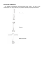
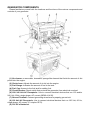
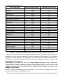
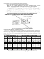
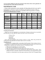
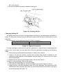
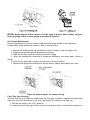
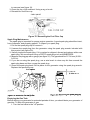
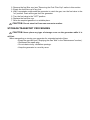
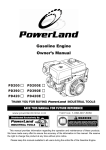
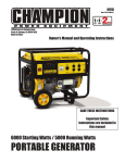
Owner’s Manual
6875 WATT GASOLINE 13HP
This manual provides information regarding the operation and maintenance of these
products. We have made every effort to ensure the accuracy of the information in this manual.
We reserve the right to change this product at any time without prior notice.
Please keep this manual available to all users during the entire life of the generator.
FEATURES
·Powerful Enough to Run Essential Appliances
·During Power Outages
·120 and 240 Volt AC Outputs
·12V DC Output for Automotive Battery Charging
·Low Oil Automatic Shutoff
·Circuit Breaker for Overload Protection
·Max Fuel Tank Capacity
·Handles and Wheels For Extra Mobility
·Meets EPA and CARB emissions standards
TABLE OF CONTENTS
GENERAL SAFETY PROCEDURES………………………………………………………………1
PACKAGE CONTENTS…………………………………………………………………………….4
GENERATOR COMPONENTS……………………………………………………………………..5
PREPARING THE GENERATOR FOR USE....…...............………………………………………6
Using the Generator for the First Time....................................…………………………...6
Step 1-Add Oil.………………………………….…………………………………..6
Step 2- Add Gasoline.…………………………………………………....................7
Step 3- Ground the Generator...................……………………………………….7
Subsequent Use of the Generator.....................…………………………………………..8
Step 1- Check the Oil..........................……………………………………………..8
Step 2-- Check the Gas Level......................……………………………………...8
Step 3- Ground the Generator...................………………………………………..8
STARTING THE GENERATOR...................……………………………………………………….9
USING THE GENERATOR...................………………………………………………………….10
AC Usage........................…………………………………………………………………10
DC Usage......................…………………………………………………………………..12
STOPPING THE GENERATOR....................……………………………………………………13
MAINTENANCE / CARE.........................………………………………………………………13
Cleaning the Generator............................................……………………………………13
Checking the Oil.........................…………………………………………………………14
Changing/Adding Oil..………………………………………………………………………14
Air Cleaner Maintenance..……………………………………………………………..15
Fuel Filter Cup Cleaning…………………………………………………………………….16
Spark Plug Maintenance....………………………………………………………………..16
Emptying the Gas Tank..………………………………………………………………….17
STORAGE / TRANSPORT PROCEDURES.................................……………………………..17
SPECIFICATIONS.....................................................……………………………………………17
TROUBLESHOOTING .............................................……………………………………………18
WIRING DIAGRAM .................................................……………………………………………20
EXPLODED VIEW AND PARTS LIST....................................…............……………………….21
Notice Regarding Emissions
Engines that are certified to comply with California and U.S. EPA emission regulations for
SORE (Small Off Road Equipment), are certified to operate on regular unleaded gasoline,
and may include the following emission control systems: (EM) Engine Modifications and
(TWC) Three-Way Catalyst (if so equipped).
GENERAL SAFETY PROCEDURES
Please familiarize yourself with the following safety symbols and words:
is used with one of the safety words (DANGER, CAUTION, or
The safety alert symbol
WARNING) to alert you to hazards. Please pay attention to these hazard notices both in this
manual and on the generator.
DANGER: Indicates a hazard that will result in serious injury or death if instructions are not
followed.
WARNING: Indicates a strong possibility of causing serious injury or death if instructions are not
followed.
CAUTION: Indicates a possibility of personal injury or equipment damage if instructions are not
followed.
DANGER: This generator produces poisonous carbon monoxide gas when
running. This gas is both odorless and colorless. Even if you do not see or smell
gas, carbon monoxide may still be present. Breathing this poison can lead to
headaches, dizziness, drowsiness, and eventually death.
·Use outdoors ONLY in non-confined areas.
·Keep several feet of clearance on all sides to allow proper ventilation of the generator.
WARNING: The exhaust from this product contains chemicals known to the State
of California to cause cancer, birth defects, or other reproductive harm.
WARNING: This generator may emit highly flammable and explosive gasoline
vapors, which can cause severe burns or even death. A nearby open flame can lead
to explosion even if not directly in contact with gas.
·Do not operate near open flame.
·Do not smoke near generator.
·Always operate on a firm, level surface.
·Always turn generator off before refueling. Allow generator to cool for at least 2 minutes
before removing fuel cap. Loosen cap slowly to relieve pressure in tank.
·Do not overfill gas tank. Gas may expand during operation. Do not fill to the top of the
tank.
·Always check for spilled gas before operating.
·Empty gasoline tank before storing or transporting the generator.
·Before transporting, turn fuel valve to off and disconnect spark plug.
WARNING: This generator produces powerful voltage, which can result in
electrocution.
·ALWAYS ground the generator before using it (see the "Grounding the Generator" portion
of the "PREPARING THE GENERATOR FOR USE" section).
·Generator should only be plugged into electrical devices, either directly or with an extension
cord. NEVER connect to a building electrical system without a qualified electrician. Such
connections must comply with local electrical laws and codes. Failure to comply can
create a backed, which may result in serious injury or death to utility workers.
·Use a ground fault circuit interrupter (GFCI) in highly conductive areas such as metal
decking or steel work. GFCIS are available in-line with some extension cords.
·Do not use in rainy or wet conditions.
·Do not touch bare wires or receptacles (outlets).
·Do not allow children or non-qualified persons to operate.
WARNING: This generator produces heat when running. Temperatures near
exhaust can exceed 150°F (65°C).
·Do not touch hot surfaces. Pay attention to warning labels on the generator denoting hot
parts of the machine.
·Allow generator to cool several minutes after use before touching engine or areas which
heat during use.
CAUTION: Misuse of this generator can damage it or shorten its life.
·Use generator only for its intended purposes.
·Operate only on dry, level surfaces.
·Allow generator to run for several minutes before connecting electrical devices.
·Shut off and disconnect any malfunctioning devices from generator.
·Do not exceed the Wattage capacity of the generator by plugging in more electrical devices
than the unit can handle (see "PRECAUTIONS-OVERLOADING THE GENERATOR").
·Do not turn on electrical devices until after they are connected to the generator.
·Turn off all connected electrical devices before stopping the generator.
In addition to the above safety notices, please familiarize yourself with the safety and
hazard markings on the generator.
PACKAGE CONTENTS
Your generator comes with the items listed below. Please check to see that all of the
following items may be included with your generator, depending on your generator model.
Screw driver
Spanner
Spark plug wrench
GENERATOR COMPONENTS
Please familiarize yourself with the locations and functions of the various components and
controls of your generator.
(1) Air cleaner- a removable, cleanable, sponge-like element that limits the amount of dirt
pulled into the engine.
(2) Choke lever- Adjusts the amount of air let into the engine.
(3) Fuel Gauge- Indicates the amount of fuel in the tank.
(4) Fuel Cap- Access to the fuel tank for adding fuel.
(5) Circuit Breaker- Reset switch that protects the generator from electrical overload.
(6) 120/ 240 Volt AC Receptacle- Use to connect electrical devices that run 120 and/or
240 Volt, 60Hz, single phase, AC current (NEMA L14-30).
(7) Ground Terminal- Connect grounding wires here to properly ground unit.
(8) 120 Volt AC Receptacle- Use to connect electrical devices that run 120 Volt, 60 Hz,
single phase, AC current (2×duplex GFCI).
(9) 12V DC of batteries.
(10) Volt Meter- Provides reading of voltage output.
(11) l2V DC Receptacle- Use for charging 12 Volt automotive-type batteries only.
(12)Oil Filler Cap- Use to Add oil or checking the oil.
(13) Oil Fill and Dipstick- Location for checking and filling engine oil.
(14) Engine Switch- Used to start/stop engine.
(15) Recoil Starter- Pull-cord for starting engine.
(16) Fuel Filter Cup- Traps dirt and water from fuel before it enters the engine.
(17) Fuel valve- Allows fuel to enter engine.
(18) Spark plug- Provides proper engine ignition.
(19) Muffler- Reduces engine noise.
PREPARING THE GENERATOR FOR USE
Using the Generator for the First Time
If you are using the generator for the first time, there are a few steps you must take to prepare
it for operation.
Step 1- Add oil
The generator requires engine oil to operate properly. The generator, when new from the
package, contains no oil in the crankcase. You must add the proper amount of oil before
operating the generator for the first time. This amount, which is equal to the oil capacity of the
engine crankcase, can be found on the chart in figure 1. When filling the engine with oil in the
future, please refer to this chart.
Model number
Engine oil capacity
PD6500E
37 fluid oz.
Figure 1- Generator Oil Capacity
CAUTION:
· Do not apply engine oil with additives or
2-stroke gasoline engine oil, as they haven’t
enough lubrication, which may shorten the
engine’s service life.
·Engine oil recommended: SAE 10W-30.
As viscosity varies with regions and
temperatures, so the lubricant has to be
selected
in
accordance
with
our
recommendation.
To add oil, follow these steps:
l. Make sure the generator is on a level surface.
2. Unscrew the oil filler/dipstick cap from the engine as shown in figure 2.
3. Using a funnel, add the appropriate amount of oil, as found in figure 1, into the crankcase.
You will know the crankcase is full when the oil level has reached the lower lip of the
opening you have just poured the oil into (see figure 3).
4. Replace oil filler cap.
Figure 2- Unscrewing the oil cap
Figure 3 - Adding oil
Step 2- Add Gasoline
WARNING: Gasoline and gas fumes are highly flammable.
·Do not fill tank near an open flame.
·Do not overfill. Always check for fuel spills.
To ensure that the generator runs smoothly use only FRESH, UNLEADED GAS WITH AN
OCTANE RATING OF 87 OR HIGHER. To add gasoline:
1. Make sure the generator is on a level surface.
2. Unscrew gas cap and set aside (NOTE: the gas cap may be tight and hard to
unscrew).
3. Slowly add unleaded gasoline to the fuel tank. Be careful not to overfill. Please refer to
the chart in figure 4 to find the gas capacity of your generator model. The fuel gauge on
the top of the generator indicates how much gasoline is in the generator gas tank.
NOTE: Gas can expand. Do not fill the gas tank to the very top.
4. Replace fuel cap and wipe up any spilled gasoline with a dry clothe.
IMPORTANT:
·Never use an oil/gasoline mixture.
·Never use old gas.
·Avoid getting dirt or water in the fuel tank.
·Gas can age in the tank and make it hard to start up the generator in the future.
Never store generator for extended periods of time with fuel in the tank.
Model number
Gas tank capacity
PD6500E
25L(6.6 us. gallons)
Figure 4 - Gas Tank Capacity
Step 3- Ground the Generator
WARNING: Failure to properly ground the generator can result in electrocution.
Ground the generator by tightening the grounding nut against a grounding wire (see figure
5). A generally acceptable grounding wire is a No. 12 AWG (American Wire Gauge) stranded
copper wire. This grounding wire should be connected at the other end to a copper or
brass-grounding rod that is driven into the end.
Grounding codes can vary by location. Please contact a local electrician to check the
grounding regulations for your area.
Figure 5 – Attaching the Grounding Wire to the Generator
Subsequent Use of the Generator
If this is not your first time using the generator there are still steps you should take to prepare it for
operation.
IMPORTANT: At this point you should be familiar with the procedures described in
the first portion of this section entitled "Using the Generator for the First Time." If
you have not yet read this section, go back and read it now.
Step 1- Check the oil
The generator is equipped with an automatic shutoff to protect it from damage due to low oil.
Nonetheless, you should check the oil level of the engine before each use to ensure that the
engine crankcase has a sufficient amount. To check the oil level:
1. Make sure the generator is on a level surface.
2. Unscrew the oil filler/dipstick cap.
3. With a dry cloth, wipe the oil off of the stick on the inside of the cap.
4. Insert the dipstick as if you were replacing the cap and then remove again. There
should now be oil on the stick. If there is no oil on the stick, or oil only at the very end of
the stick, you should add oil until the engine crankcase is filled (see "Adding Oil"
portion of the "Maintenance" section).
5. Be sure to replace cap when finished checking oil.
NOTE: The oil capacity for your generator can be found in the "Specifications" section of this
manual.
Step 2 - Check the Gas Level
Before starting the generator, check to see that there is sufficient gasoline in the gas tank.
The fuel gauge on top of the generator will indicate the gas level in the tank. Add gas if
necessary according to the steps in the "Adding Gasoline" portion of the "Maintenance"
section.
WARNING: Gasoline and gasoline fumes arc highly flammable.
·Do not fill tank near an open flame.
·Always allow engine to cool for several minutes before refueling.
·Do not overfill (check the "Specifications" section for the tank capacity of your
generator). Always check for fuel spills.
IMPORTANT:
·Use only UNLEADED gasoline with an octane rating of 87 or higher.
·Do not use old gas.
·Never use an oil/gasoline mixture.
·Avoid getting dirt or water in the fuel tank.
·Never store generator for extended periods of time with fuel in the tank.
Step 3- Ground the Generator
WARNING: Failure to properly ground the generator can result in electrocution.
Ground the generator by tightening the grounding nut against a grounding wire (see J
figure 5). A generally acceptable grounding wire is a No. 12 AWG (American Wire Gauge)
stranded copper wire. This grounding wire should be connected at the other end to a copper
or brass-grounding rod that is driven into the earth.
Grounding codes can vary by location. Please contact a local electrician to check the
grounding regulations for your area.
STARTING THE GENERATOR
CAUTION: Disconnect all electrical loads from the generator before attempting
to start.
To start your generator, perform the following steps:
l. Make sure no electrical devices are connected to the generator. Such devices can
make it difficult for the engine to start.
2. Check that the generator is properly grounded (see page 13, "Ground the
Generator").
3. Turn the fuel valve to the "on" position (see figure 6).
4. Move the choke lever to the "closed" position (see figure 7).
5. Set the engine switch to the "on" position.
6. Pull on the recoil starter handle slowly until a slight resistance is felt (see figure 8).
Then pull quickly to start the engine. Return cord gently into the machine. Never allow
the cord to snap back.
7. If engine fails to start, repeat step 4. NOTE: After repeated attempts to start the
engine, please consult the troubleshooting guide before attempting again.
8. Once the engine has started and run for about a minute, move the choke lever about
half way towards the "open" position. Wait another 30 seconds and then move the
choke lever all the way to the "open" position.
9. Allow the generator to run for several minutes before attempting to connect any
electrical devices.
USING THE GENERATOR
Once you have allowed the engine to run for several minutes, you may connect electrical
devices to the generator.
AC Usage
You may connect electrical devices running on AC current according to their wattage
requirements. The chart in figure 9 shows the rated and surge wattage of your generator according
to its model number.
The rated wattage corresponds to the maximum wattage the generator can output on a
continuous basis.
The surge wattage corresponds to the maximum amount of power the generator can output
for a short period of time. Many electrical devices such as refrigerators require short bursts of
extra power, in addition the rated wattage listed by the device, to stop and start their motors.
The surge wattage ability of the generator covers this extra power requirement.
Model Number
Rated (Running) Wattage
Surge Wattage
5500
6875
PD6500E
Figure 9-generator wattage by model number
The total running wattage requirement of the electrical devices connected to the generator
should not exceed the rated wattage of the generator itself. To calculate the total wattage
requirement of the electrical devices you wish to connect, find the rated (or running) wattage
of each device. This number should be listed somewhere on the device or in its instruction
manual. If you cannot find this wattage, you may calculate it by multiplying the Voltage
requirement by the Amperage drawn:
Watts= Volts × Amperes
If these specifications are not available you may estimate the Watts required by your device
by using the chart in figure 10.
Tool or Appliance
Electric water heater (40 gal)
Hot plate
Saw-radial arm
Electric stove
Saw-circular
Air compressor (1HP)
Window air conditioner
Saw-miter
Microwave
Well water pump
Reciprocating saw
Sump pump
Refrigerator freezer
Furnace blower
Computer
Electric drill
Television
Deep freezer
Garage door opener
Stereo
Box fan
Clock radio
Security system
DVD player/VCD
Common light bulb
Rated (Running) Watts
4000
2500
2000
1500
1500
1500
1200
1200
1000
1000
960
800
800
800
800
600
500
500
480
400
300
300
180
100
75
Additional Surge Watts
0
0
2000
0
1500
3000
1800
1200
0
1000
1040
1200
1200
1300
0
900
0
500
0
0
600
0
0
0
0
Figure 10- Estimated wattage requirements of common electrical devices.
Once you have found the rated wattage requirement of each electrical device, add these
numbers to find the total rated wattage you wish to draw from the generator. If this number
exceeds the rated wattage of the generator, DO NOT connect all these device, Select a
combination of electrical devices, which has a total rated wattage lower than or equal to the
rated wattage of the generator.
CAUTION-The generator can run at its surge wattage capacity for only a short time.
Connect electrical devices requiring a rated (running) wattage equal to or less than the rated
wattage of the generator. Never connect devices requiring a rated wattage equal to the surge
wattage of the generator.
NOTE: The above wattage figures are estimates. Try to check the wattage listed on your
electrical device before consulting this chart.
Once you have determined what electrical devices you will be powering with the generator,
connect these devices according to the following procedure:
1. Plug in each electrical device with the device turned off.
NOTE: Be sure to attach appliances to the correct receptacle (outlet). Connect
standard 120 Volt, single phase, 60 Hz loads only to the 120 Volt receptacles.
Connect 120/240 Volt, single phase, 60Hz loads with NEMA L14-30 plug only to
the 120/240 Volt receptacle See Figure 11 for a depiction of each of these
receptacles.
2. Switch the circuit breaker to the "on" position.
3. Turn on the connected electrical devices in the order of the amount of power they
require beginning with the device with the highest rated Wattage requirement.
CAUTION: Do not connect 50Hz or 3-phase loads to the generator.
Figure 11- Receptacles available on the generator
SOME NOTES ABOUT POWER CORDS
Long or thin cords can drain the power provided to an electrical device by the generator.
When using such cords, allow for a slightly higher rated wattage requirement by the electrical
device. See Figure 12 for recommended cords based on the power requirement of the
electrical device.
Device Requirements
Max. Cord Length (ft) by Wire Gauge
Watts
Watts
#8 wire #10 wire
#12 wire #14 wire #16 wire
(120V)
(240V)
2.5
300
600
NR
1000
600
375
250
5
600
1200
NR
500
300
200
125
7.5
900
1800
NR
350
200
125
100
10
1200
2400
NR
250
150
100
50
15
1800
3600
NR
150
100
65
NR
20
2400
4800
175
125
75
50
NR
25
3000
6000
150
100
60
NR
NR
30
3600
7200
125
65
NR
NR
NR
40
4800
9600
90
NR
NR
NR
NR
*NR= not recommended
Figure 12-Maximum Extension Cord Lengths by Power Requirement
Amps
DC Usage
CAUTION: The DC receptacle is for recharging 12 Volt automotive-type batteries only.
Do not connect any other device to this receptacle.
CAUTION: Use the generator only to recharge 12 Volt batteries. Never try to jumpstart
a car with your generator.
To connect 12 Volt batteries to the DC receptacle:
1. Connect one charging wire to the positive terminal on the battery and the other
charging wire to the negative terminal.
2. Connect the free end of the positive wire to the positive receptacle (outlet) on the
generator.
3. Start the generator.
4. Carefully connect the free end of the negative wire to the negative receptacle on the
generator.
5. When disconnecting, always disconnect the wires from the generator first to avoid a
spark.
DANGER: Storage batteries emit highly explosive hydrogen gas when charged.
Batteries also contain acid, which can cause severe chemical burns.
·Do not allow open flames or cigarettes nearby for several minutes after charging
a battery.
·Always wear protective goggles and rubber gloves when charging a battery.
☆ If battery acid gets on your skin, flush with water.
☆ If battery acid gets in your eyes, flush with water and call a physician
immediately.
☆ If battery acid is swallowed, drink large quantities of milk and call a
physician immediately.
If the generator you buy is electric start one, once beginning to work, it will charge the
battery on the generator automatically. At this time, you can see the indicator light is shining,
after the battery is full, the light will be extinct.
STOPPING THE GENERATOR
To stop the generator:
1. Turn off, then unplug all connected electrical devices.
2. Switch the circuit breaker to the "off' position.
3. Allow the generator to run for several more minutes with no electrical devices
connected. This helps stabilize the temperature of the generator.
4. Set the engine switch to the "off' position.
5. Turn the fuel valve to the "off' position.
WARNING: Allow the generator to cool for several minutes before touching
areas that become hot during use.
CAUTION: Allowing gas to sit in the generator tank for long periods of time without
use can make it difficult to start the generator in the future. Never store generator for
extended periods of time with fuel in the tank.
MAINTENANCE /CARE
Proper routine maintenance of your generator will help prolong the life of your machine.
Please perform maintenance checks and operations according the schedule in figure 13.
CAUTION: Never perform maintenance operations while the generator is running.
Recommended Maintenance schedule
Each
use
Engine oil
Check level
Check
Every
year or
300 hrs
×
×
×
Clean
Fuel
filter Clean
cup
Check/clean
Spark plug
Check
gas
Gas tank
level
Clean
Every 3
Every 6
months or months or
50 hrs
100 hrs
×
Replace
Air cleaner
Every
month or
12 hrs
×
×
×
7
Figure 13- Recommended maintenance schedule
×
Cleaning the Generator
Always try to use your generator in a cool dry place. However, in the event your generator
becomes dirty you may clean the exterior with one or more of the following:
- A damp clothe
- A soft brush
- A vacuum
- Pressurized air
Never clean your generator with a bucket of water or a hose. Water can get inside the
working pats of the generator and cause a short circuit or corrosion.
Checking the Oil
The generator is equipped with an automatic shutoff to protect it from running on low oil.
Nonetheless, you should check the oil level of the generator before each use to ensure that
the generator crankcase has a sufficient amount. To check the oil level:
1. Make sure the generator is on a level surface.
2. Unscrew the oil filler/dipstick cap (see figure 14).
3. With a dry cloth, wipe the oil off of the stick on the inside of the cap.
4. Insert the dipstick as if you were replacing the cap and then remove again. There
should now be oil on the stick. If there is no oil on the stick, or oil only at the very end of
the stick, you should add oil until the engine crankcase is filled. See "Changing/ Adding
Oil" in this section.
5. Be sure to replace cap when finished checking oil.
Figure 14- Checking the Oil
Changing/ Adding Oil
You should check the oil level of your generator according to the maintenance schedule in
figure 13. When the oil level is low you will need to add oil until the level is sufficient to run the
generator.
The oil capacity of your generator engine is listed in figure 15.
Model number
PD6500E
37 fluid oz.
Engine oil capacity
Figure 15- Engine Oil Capacity.
It is only necessary to drain the oil from the crankcase if it has become contaminated with
water or dirt. In this case, you can drain the oil from the generator according to the following
steps:
1. Place a bucket underneath the generator to catch oil as it drains.
2. Using a 10 mm hex wrench, unscrew the oil drain plug, which is located on the
crankcase underneath the oil filler/dipstick cap (see figure 16). Allow all the oil to drain
from the generator.
3. Replace the oil drain plug and tighten with a 10 mm hex wrench.
To add oil to the crankcase, follow these steps:
1. Make sure the generator is on a level surface.
2. Unscrew the oil filler/dipstick cap from the engine as shown in figure 14 above.
3. Using a funnel, add high detergent motor oil to the crankcase. We recommend SAE
10W30 motor oil for general use. When full, the oil level should come close in the top of
the oil fill opening (see figure 17).
NOTE: Never dispose of used motor oil in the trash or down a drain. Please call your
local recycling center or auto garage to arrange oil disposal.
Air Cleaner Maintenance
Routine maintenance of the air cleaner helps maintain proper airflow to the carburetor.
Occasionally check that the air cleaner is free of excessive dirt.
l. Unhinge the clasps at the top and bottom of the air cleaner cover (see figure 18).
2. Remove the sponge-like elements from the casing.
3. Wipe the dirt from inside the empty air cleaner casing
4. Wash the sponge-like elements in household detergent and warm water. Allow to
drying.
5. Soak the dry elements in engine oil. Squeeze out any excess oil.
6. Replace the sponge-like elements in the air cleaner casing and replace the cover.
Figure 18- Removing the air cleaner casing.
Fuel Filter Cup Cleaning
The fuel filter cup is a small well underneath the fuel valve. It helps to trap dirt and water that
may be in your fuel tank before it can enter the engine. To clean the fuel filter cup:
1. Turn the fuel valve to the "OFF' position.
2. Unscrew the fuel filter cup from the fuel valve using a wrench. Turn the valve toward you
to unscrew (see figure 19).
3. Clean the cup of all sediment. Using a rag or brush.
4. Reinstall the fuel filter cup.
Figure 19 –Removing the Fuel Filter Cup
Spark Plug Maintenance
The spark plug is important for proper engine operation. A good spark plug should be intact,
free of deposits, and properly gapped. To inspect you spark plug:
1. Pull on the spark plug cap to remove it.
2. Unscrew the spark plug from the generator using the spark plug wrench included with
this product (see figure 20).
3. Visually inspect the spark plug. If it is cracked or chipped, discard and replace with a new
spark plug. We recommend using a F6RTC spark plug such as NGKBPR5ES.
4. Measure the plug gap with a gauge (see figure 21). The gap should be 0.7-0.8 nun (0.028—
0.031 in).
5. If you are re-using the spark plug, use a wire brush to clean any dirt from around the
spark plug base and then re-gap the spark plug.
6. Screw the spark plug back into its place on the generator using the spark plug wrench.
Replace the spark plug cap.
Emptying the Gas Tank
Before storing your generator for extended periods of time, you should drain your generator of
gasoline. To drain the generator of gas:
1. Turn the fuel valve to the "off' position.
2. Remove the fuel filter cup (see "Removing the Fuel Filter Cup" earlier in this section.
3. Empty the fuel filter cup of any fuel.
4. With a receptacle underneath the generator to catch the gas, turn the fuel valve to the
"on" position. Drain all the gas from the generator.
5. Turn the fuel valve to the "OFF" position.
6. Replace the fuel filter cup.
7. Store the emptied gasoline in a suitable place.
CAUTION: Do not store fuel from one season to another.
STORAGE/TRANSPORT PROCEDURES
CAUTION: Never place any type of storage cover on the generator while it is
still hot.
When transporting or storing your generator for extended periods of time:
·Empty the gas tank (see "Emptying the Gas Tank" in the "Maintenance" section).
·Disconnect the spark plug.
·Do not obstruct any ventilation openings.
·Keep the generator in a cool dry area.
SPECIFICATIONS
Generator
AC Output
PD6500E
5500W
6875W
120/240V
60Hz
Single
Rated Wattage
Surge Wattage
Rated Voltage
Rated Frequency
Phase
DC Output
PD6500E
12V
8.3A
Length=28 width=20 height=21.3
Voltage
Amperage
Dimensions (in):
Engine
Engine type
Ignition system
Displacement
Starting type
Fuel tank capacity:
Oil capacity
Run time on 50% load
Noise Level
PD6500E
4-stroke OHV single cylinder with forced air cooling
system
Non-contact transistor
389cc
Electric start /Recoil
25L(6.6US gal.)
1.1L(37fl oz.)
10hrs
75dB@7m (22 feet)
TROUBLESHOOTING
Problem
Cause
Engine will not Engine switch is set to “off”.
start
Fuel valve is turned to “closed”.
Choke is open.
Engine is out of gas.
Engine
is
filled
with
contaminated or old gas
Spark plug is dirty.
Spark plug is broken.
Generator
surface.
is
not
on
Solution
Set engine switch to “on”.
Turn fuel valve to “open” position.
Close the choke
Add gas.
Change the gas on the engine.
Clean spark plug.
Replace spark plug.
Move generator to a level surface to
level
prevent low oil shutdown from
triggering.
Oil is low
Add or replace oil.
Set the circuit breaker to the “on”
position.
If you are using an extension cord,
try a different one.
Circuit breaker is off.
Engine runs but
there
is
no Bad connecting wires/cables.
electrical output
Bad
electrical
device
Try connecting a different device.
connected to generator.
Try connecting fewer electrical loads
Generator
runs Generator is overloaded
to the generator.
but
does
not
support
all Short in one of the connected Try disconnecting any faulty or
short-circuited electrical loads.
electrical devices devices.
connected.
Air cleaner is dirty.
Clean or replace air cleaner.
GENERATOR ASSEMBLY AND MOUNTING
Generator is supplied with a wheel kit. If you want to install the wheel kit on your unit,
please follow the instructions below. If you will not be using the wheel kit, skip this section.
1. Place the bottom of the generator cradle on a flat, even surface. Temporarily place unit
on blocks to ease assembly.
2. Secure the support leg to the cradle with cap screws (M8 x 16) and lock nuts (M8) (see
figure 22 ).
3. Secure the axle to the cradle with cap screws (M8 x 16) and lock nuts (M8) (see figure
23).
4. Slide a wheel (with the inflation valve facing out) and a flat washer over the axle, then
secure the wheel with a retaining pin (see figure 24、Figure 25、Figure 26).
5. Position the handles on the cradle and attach with plastic flat washer, cap screws(M8
X 16) and lock nuts(M8)( Figure 27、Figure 28).
5. Check that all fasteners are tight and tires are inflated between 15-40 PSI.
Figure 22
Figure 23
Figure 24
Figure 25
Figure 28
CHANGE THE CARBON-BRUSH
Figure 26
Figure 27
CHANGE THE AVR
WIRING DIAGRAM
EXPLODED VIEW AND PARTS LIST
Item
Part
1
Qty
Description
Item
Part
Qty
Description
1
Gasoline engine
42
14400
1
Fuel sensor
2
15100
1
Frame comp
43
GB 819-95
2
Screw M5×10
3
15002
2
Bottom rubber A
44
14410
1
Casket fuel tank
4
15003
2
Bottom rubber B
45
GB5787-86
4
Flange bolt M6×22
5
GB6177-86
12
Flange nut M8
46
14022
4
Washer
6
GB802-88
4
Flange nut M6
47
14005
4
Collar
7
41350
4
Cushion, frame
48
14001
4
Cushion
8
GB5787-86
4
Bolt M6×12
49
14004
1
Outlet pipeφ4.5×165
9
15001
2
Rubber pad, frame
50
14006
2
Tube clip
10
15201
2
Hand push
51
14003
1
Rubber, fuel tube
11
11010
1
Earth terminal set
52
14100
1
Fuel cock
12
GB5787-86
8
Flange bolt M6×12
53
13001
1
Protector comp muffler
13
11070
1
Receptacle (30A)
54
GB5787-86
4
Flange bolt M6×14
14
11092
1
Receptacle (20A)
55
GB5787-86
2
Flange bolt M8×32
15
11072
1
Receptacle (20A)
56
13010
1
Muffler stay
16
11120
2
Circuit protector
57
13020
1
Muffler
17
11090
1
Control panel
58
13002
1
Protector muffler inner
18
11110
1
Voltmeter
59
GB5789-86
4
Flange bolt M8×16
19
11050
2
Diode assay
60
13004
1
Seal protector muffler
20
11082
1
Engine switch
61
13005
1
Muffler, stay comp
21
11040
1
Boot, switch wire
62
13003
1
Protector muffler side
22
11030
1
Boot, main wire harness
63
11091
1
Control panel case
23
11010
1
Boot, AC output wire
64
11101
2
DC output post
24
11060
1
Wire harness Assy.
65
21000
1
Wheel Assy.
25
GB5787-86
2
Flange bolt M5×12
66
21050
2
Pin.
26
16004
1
Generator end cover
67
GB97.1-85
2
Washer φ20
27
GB5789-86
4
Flange bolt M6×175
68
21040
2
Wheel comp
28
16003
1
Support stand
69
21020
2
Bracket
29
GB5789-86
1
Bolt M10×1.25×265
70
21010
1
Well shaft
30
GB9701-85
1
Plain washerφ10
179
20053
1
Fuse
31
GB276-89
1
Bearing 6207-2RS
180
22001
1
Positive wire of battery
32
16200
1
Rotor comp
181
22002
1
Negative wire of battery
33
16000
1
Stator & Rotor Assy.
182
22005
1
Battery cover
34
16005
1
Generator fan
183
22010
1
Battery
35
16101
1
Stator cover
184
13030
1
Brush assy.
36
16100
1
Stator Assy.
185
13040
1
Voltage regulator
37
14201
1
Stripe, fuel tank
38
14200
1
Fuel tank
39
14302
1
Fuel filter
40
14303
1
Packing ring
41
14300
1
Fuel filler cap comp
Item
Part
Qty
71
21100
1
72
GB5787-86
73
Description
Item
Part
Qty
Starter comp, recoil
112
11219
1
Casket, cylinder head
3
Flange bolt M6×8
113
11218
2
Bolt head, 8×10⁶
12310
1
Fan, cover comp
114
23008
2
Packing, air cleaner
74
GB5787-86
13
Flange bolt M6×12
115
22000
1
Stay assy. Manual choke
75
19003
1
Shroud comp
116
12012
1
Grommet fender
76
12302
3
Clip. Wire darkness
117
23000
1
Carburetor assy.
77
12302
1
Grommet drain hole
118
23002
1
Packing, carburetor
78
21000
1
Start motor
119
23001
1
Insulator, carburetor
79
GB5789-86
2
Flange bolt M8×35
120
GB6177-86
4
Flange nut M6
80
GB6177-86
1
Flange nut M16
121
12006
1
Stay, air cleaner
81
19005
1
Pulley, starter
122
12005
1
Case comp, air cleaner
82
19001
1
Fan, cooling
123
12004
1
Separator, air cleaner
83
GB/T 99-88
1
Key
124
GB6177-86
6
Flange nut M5
84
81200
1
Flywheel comp
125
12007
1
Cover comp, air cleaner
85
12215
2
Oil seal, 35×52×8
126
12008
2
Clip, air cleaner ware
86
12200
1
Crank case assy.
127
12003
1
Element, air cleaner
87
87500
1
Amplifier
128
12010
1
Seal, air cleaner
88
12203
2
Bolt, drain lug
129
23003
1
Packing, insulator
89
12217
2
Washer, drain lug
130
23011
4
Clip, tube
90
87601
1
Clip, wire
131
23006
1
91
21012
1
Protect board A
132
91009
1
Tube, fuel φ45×165
92
GB5789-86
4
Flange bolt M6×30
133
12001
1
Tube, breather
93
GB5789-86
2
Flange bolt M6×25
134
GB5789-86
4
Flange bolt M10×80
94
21011
1
Protect board B
135
11250
1
Head comp, cylinder
95
21000
1
Coil assy. excitation
136
11217
2
Bolt head, M8×34
96
22000
1
Coil assy. AC 12V (10A)
137
11202
1
Plug, spark
97
81102
1
Cord stop switch
138
15100
1
Camshaft assy.
98
81103
1
Grommet cord
139
15002
2
Lifter, valve
99
81100
1
Coil assy. ignition
140
11208
1
Valve, IN.
100
12216
Oil seal, 8×14×5
141
11209
1
Valve, EX.
101
GB/T276-94
2
142
11216
1
Seat, valve spring
102
12208
1
Shaft, governor arm
143
11212
1
Retainer, EX. Valve spring
103
12212
1
Pin, lock, 10mm
144
11213
1
Rotator, valve
104
12209
1
Washer, 8.2×17×0.8
145
11211
1
Retainer, IN. Valve spring
105
GB6177-86
1
Flange nut M10
146
11206
2
Spring, valve
106
12221
1
O-ring,14mm
147
15001
2
Rod, push
107
12200
1
Switch assy. oil level
148
11241
1
Exhaust piper
108
13200
1
Weight, balancer
149
11240
1
Cover comp, head
109
13000
1
Crankshaft comp
150
11243
1
110
GB/T276-94
2
Radial ball bearing (6207)
151
11242
1
Bolt, head cover
111
12220
2
Pin, dowel, 12×20
152
GB6175-86
2
Nut M8
Radial ball bearing (6202)
Description
Valve, dashpot check assy.
Washer comp head cover
153
13200
1
Pipe comp EX.
154
13202
1
Casket (B) EX. Pipe
155
11215
1
Plate, push rod guide
156
11214
2
Bolt, pivot
157
11205
2
Arm, valve rocker
158
11204
2
Nut, Arm, valve rocker
159
11206
2
Nut, pivot adjusting
160
GB5789-86
7
Flange bolt M8×40
161
12100
1
Crankcase cover
162
GB5789-86
3
Flange bolt M5×10
163
12301
1
Fan cover
164
121102
1
Cap assy. oil filler
165
12230
1
Governor kit
166
12214
1
Packing, case cover
167
12213
2
Pin, dowel, 8×12
168
13100
1
Ping set assy. piston
169
13105
2
Clip, piston pin
170
13101
1
Piston
171
13104
1
Pin, piston
172
13106
1
Connecting rod assy.
173
17220
1
Control assy.
174
17001
1
Spring, governor
175
17002
1
Spring, throttle return
176
17004
1
Arm, governor
177
17003
1
Rod, governor
178
17005
1
Bolt, governor arm