1
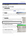
SATEL I-LINK PC Pro
User Guide, E, V1.2
USER MANUAL
SATEL I-LINK PC Pro
Routing program
for
Point-to-Multipoint Operation
1
SATEL I-LINK PC Pro
User Guide, E, V1.2
1
TABLE OF CONTENTS
1
TABLE OF CONTENTS.................................................................................................2
2
GENERAL......................................................................................................................4
2.1 ABOUT SATEL I-LINK PC PRO ............................................................................................................. 4
3
INITIAL SETTINGS........................................................................................................5
3.1 SATELLINE RADIO MODEM AND SATEL I-LINK 100 CONFIGURATIONS ................................... 5
3.1.1
3.1.2
3.1.3
3.1.4
4
Baud Rate ..................................................................................................................................................................................5
Protocol ......................................................................................................................................................................................5
Address ......................................................................................................................................................................................5
Connections ...............................................................................................................................................................................5
HOW TO START USING OF THE PROGRAM .............................................................6
4.1 QUICK START ....................................................................................................................................... 6
4.1.1
4.1.2
4.1.3
Operation Window .....................................................................................................................................................................6
COM-Port...................................................................................................................................................................................6
Slave address ............................................................................................................................................................................6
4.2 SENDING DIGITAL DATA..................................................................................................................... 6
4.3 SENDING ANALOG DATA.................................................................................................................... 6
5
EDIT MODES.................................................................................................................7
5.1
5.2
5.3
5.4
HOW TO SELECT FUNCTIONS .......................................................................................................... 7
SET NAME.............................................................................................................................................. 7
SET SLAVE ADDRESS ......................................................................................................................... 7
SAFE MODE SETTINGS (DIAGNOSTICS) .............................................................................................. 7
5.4.1
5.4.2
5.4.3
5.4.4
5.4.5
5.4.6
Normal........................................................................................................................................................................................7
Alarm only ..................................................................................................................................................................................7
Ports Low ...................................................................................................................................................................................7
Ports High ..................................................................................................................................................................................7
Defined Ports .............................................................................................................................................................................7
Safe Mode Time ........................................................................................................................................................................7
5.5 SET UPDATE TIME ............................................................................................................................... 8
5.6 SET UPDATE MODE (CONCERNS ONLY RECEIVED DATA) ..................................................................... 8
5.6.1
5.6.2
5.6.3
Manual update ...........................................................................................................................................................................8
Automatic update.......................................................................................................................................................................8
Time based update....................................................................................................................................................................8
5.7 SET LAYOUT STYLE ............................................................................................................................ 8
5.8 SET UNIT CONVERSION ..................................................................................................................... 9
5.9 CONNECTION TYPE............................................................................................................................. 9
5.10 SHOW SLAVE VERSION...................................................................................................................... 9
5.11 LOAD SETTINGS................................................................................................................................... 9
5.12 SAVE SETTINGS................................................................................................................................... 9
5.13 CLOSE (CLOSE THE SLAVE)..................................................................................................................... 9
5.14 CLOSE (CLOSE THE I-LINK PC PRO PROGRAM) .................................................................................... 9
5.15 SAVE ALL SLAVES ............................................................................................................................. 10
5.16 LOAD ALL SLAVES ............................................................................................................................. 10
5.17 EDIT ...................................................................................................................................................... 10
6
FILE-MENU..................................................................................................................11
6.1
6.2
6.3
6.4
6.5
6.6
6.7
7
NEW SLAVE......................................................................................................................................... 11
LOAD SLAVE(S) ................................................................................................................................... 11
SAVE ALL SLAVES ............................................................................................................................. 11
CLOSE ALL SLAVES .......................................................................................................................... 11
LOAD WORKSPACE ........................................................................................................................... 11
SAVE WORKSPACE ........................................................................................................................... 11
EXIT ...................................................................................................................................................... 11
MASTER CONFIG-MENU ...........................................................................................12
7.1 COM-PORTS 1…8............................................................................................................................... 12
7.1.1
Open new Com-Port................................................................................................................................................................12
2
SATEL I-LINK PC Pro
User Guide, E, V1.2
7.1.2
How to use Com-Ports ............................................................................................................................................................12
7.2 SET MASTER ADDRESS ................................................................................................................... 12
7.3 SETTINGS ............................................................................................................................................ 13
7.3.1
7.3.2
Auto Boot .................................................................................................................................................................................13
Activation .................................................................................................................................................................................13
7.4 ALARM.................................................................................................................................................. 13
7.4.1
7.4.2
7.4.3
7.4.4
7.4.5
Activation .................................................................................................................................................................................13
Resend Count..........................................................................................................................................................................13
Alarm Time...............................................................................................................................................................................14
Alarm Attention Type ...............................................................................................................................................................14
Alarm List Window...................................................................................................................................................................14
7.5 LAYOUT................................................................................................................................................ 14
8
WINDOW-MENU..........................................................................................................15
8.1 SHOW ACTION LOG........................................................................................................................... 15
8.1.1
8.1.2
8.1.3
8.1.4
Save Log..................................................................................................................................................................................15
Clear Log .................................................................................................................................................................................15
Clear Log File ..........................................................................................................................................................................15
Stream to file............................................................................................................................................................................15
8.2 SHOW ALARM LIST ............................................................................................................................ 16
8.3 SHOW ROUTE LIST EDITOR ............................................................................................................ 16
8.4 SHOW CHANNEL SELECTOR........................................................................................................... 16
8.4.1
8.4.2
8.4.3
8.4.4
8.4.5
8.4.6
8.4.7
9
Change Master Channel .........................................................................................................................................................17
Check Current Channel...........................................................................................................................................................17
Change To Selected Channel .................................................................................................................................................17
Fast Scan All Channels ...........................................................................................................................................................17
Deep Scan All Channels .........................................................................................................................................................17
Ping Slaves ..............................................................................................................................................................................17
Find Slaves ..............................................................................................................................................................................17
ROUTING.....................................................................................................................18
9.1 START .................................................................................................................................................. 19
9.1.1
9.1.2
9.1.3
9.1.4
9.1.5
9.1.6
9.1.7
9.1.8
10
Route List Editor ......................................................................................................................................................................19
New Route ...............................................................................................................................................................................19
Edit ...........................................................................................................................................................................................20
Delete.......................................................................................................................................................................................20
Clear All ...................................................................................................................................................................................20
Save as Text............................................................................................................................................................................20
Close ........................................................................................................................................................................................20
Reminder .................................................................................................................................................................................20
INDICATORS.............................................................................................................21
10.1 ADJUSTABLE SETTINGS................................................................................................................... 21
10.2 BOTTOM BAR, SLAVE ......................................................................................................................... 21
10.3 BOTTOM BAR, MASTER....................................................................................................................... 21
11
FACTORY SETTINGS AND ACCESSORIES ...........................................................22
11.1 ACCESSORIES.................................................................................................................................... 22
11.1.1
11.1.2
12
Interface Cables for SATEL I-LINK 100................................................................................................................................22
Extension units I-LINK 200 and 300 .....................................................................................................................................22
CONNECTION EXAMPLE.........................................................................................23
3
SATEL I-LINK PC Pro
User Guide, E, V1.2
2
2.1
GENERAL
ABOUT SATEL I-LINK PC Pro
SATEL I-LINK PC P r o is a Point-to-Multipoint program that can be used to drive several
SATEL I-LINK 100 slaves connected to SATELLINE radio modems. The maximum number of
slaves is 255. The program makes it possible to operate systems, which are connected to the
I/O -ports, to change values, monitor the radio link and Multipoint operation etc.
With the routing feature any of the slave’s digital/analogue Input can be routed to any
digital/analogue Output. You can even route any one of the inputs to several or all outputs.
This feature is useful for example emergency multi-alarm e.g. routing is done by the PCprogram, which virtually connects the Inputs to the defined Outputs. The Input can be connected
to the any Output or to the same I-LINK 100…300. You may thus use this as switch isolator,
current converter and voltage converter from 12-24 VDC to 230 VAC etc.
Analogue Inputs can also be routed to Analogue Outputs.
Minimum requirements:
PC 286, SATELLINE radio modem, SATEL I-LINK100, I-LINK PC Pro PROGRAM
COM Port baud rate min. 9600 b/sec. Windows 95, 98, 2000, XP.
Small Multipoint system
Routed Multipoint system
4
SATEL I-LINK PC Pro
User Guide, E, V1.2
3
INITIAL SETTINGS
3.1 SATELLINE RADIO MODEM AND SATEL I-LINK 100
CONFIGURATIONS
3.1.1 Baud Rate
Set the baud rate of the SATELLINE radio modem. Check that the other parameters are “N-8-1”.
Set the baud rate of the SATEL I-LINK 100 by using the BAUD DIP -switches.
00=2.4, 10=4.8, 01=9.6, 11=19.2 (Check that the SATELLINE radio modems have the same
settings).
3.1.2 Protocol
Set the SATEL I-LINK 100 PRTCL switch to the Multipoint position, P-to-MP.
3.1.3 Address
Set personal addresses to all SATEL I-LINK 100 slaves by using the ADDRESS DIP-switches.
3.1.4 Connections
Before connecting the device to a power supply, first connect all inputs and outputs. There is
more information about connections at the end of the manual.
5
SATEL I-LINK PC Pro
User Guide, E, V1.2
4
4.1
HOW TO START USING OF THE PROGRAM
QUICK START
Open the SATEL I-LINK PC Pro program.
4.1.1 Operation Window
Open a new operation window(s) from the toolbar list by clicking the
-button on the upper
left corner, or Open by clicking on the File Menu, opening "New Slave". Open own window for
all Slaves. Note, that the maximum number of Slaves in this program is 255. Arrange the
display by using the Windows Menu or the
-buttons.
4.1.2 COM-Port
Open COM- port from the toolbar list by clicking
“Master Config” – “Port1…4” and “Open”. Select
COM-port and set the same parameters as you have set for the SATELLINE radio modem and
SATEL I-LINK 100, and press OK. If there are no COM -port settings, the program will
automatically ask for them.
4.1.3 Slave address
When the new slave is opened, the program will automatically set the address
for it. To make manual adjustments, click anywhere on the empty grey area of
the slave window using the right mouse button, and select “Set Slave address”.
Insert the new address, and then press OK.
The basic settings have now been established and the SATEL I-LINK PC Pro
is ready to send and receive.
4.2
SENDING DIGITAL DATA
To change the slave's digital value, click the gray “Digital
Output” circle dot. During the transmission the dot is
yellow. When the transmission is done, the circle will
change to green. If the transmission fails, the “Operation”
signal will turn red.
4.3
SENDING ANALOG DATA
Move the “Analog Output Cursor” or change the number
at the side. Press “Send Analog Data” and the levels will
be sent to the Slave's “Analog Output”.
If the transmission fails, the “Operation” signal will turn red. Note that “Analog Output” can
only be sent by pressing “Send Analog Data”.
6
SATEL I-LINK PC Pro
User Guide, E, V1.2
5
EDIT MODES
5.1 HOW TO SELECT FUNCTIONS
Click anywhere on the empty grey area of the slave window
using the right mouse button. This will open a new window
where you can select the desired function.
5.2 SET NAME
The default name I-Link1 can be changed using this function.
Select "Set Name" – type the new name and press OK.
5.3
SET SLAVE ADDRESS
Select “Set Slave address”. Insert the new address and press OK.
5.4
SAFE MODE SETTINGS (diagnostics)
The Safe Mode Setting defines what should be done to the slave’s outputs, if the
slave has not been contacted by the master in the pre-set Safe Mode Time. This function acts like
diagnostics to the slave units.
5.4.1 Normal
The outputs will remain their
current position.
5.4.2 Alarm only
Alarm LED will be lit and the
outputs will remain their
current position.
5.4.3 Ports Low
Alarm LED will be lit and the
outputs will go OFF.
5.4.4 Ports High
Alarm LED will be lit and the outputs will go ON.
5.4.5 Defined Ports
Alarm LED will be lit and the outputs will go to pre-set state.
5.4.6 Safe Mode Time
The pre-set time defines the time when the slave will
make the above pre-set actions, if the slave has not got
been contacted by the master. The minimum increment
time is 1 minute.
7
SATEL I-LINK PC Pro
User Guide, E, V1.2
5.5 SET UPDATE TIME
Defines the interval how often the master contacts the slaves. The time can be from 1 second up
to …24 hours. Select "Set Update Time”, set the time and press SET.
5.6
SET UPDATE MODE (concerns only received data)
The update mode defines the way how the master contacts the slaves.
When this action happens, the master sends a GET command (asking only for
slave’s status) to the slave and the slave answers with its status. The GET
command d oe s not update any of the slave’s Digital or Analogue Outputs. The GET is also an
update to the slave’s diagnostics timer. There are 3 different modes to receive Data; Manual,
Automatic or Time. The settings can be done separately for each slave.
5.6.1 Manual update
Select “Set update mode”, and press “Manual”. Using this setting, the slave information for the
chosen window is updated only when “Manual Update” circle-dot in the slave window is
pressed.
5.6.2 Automatic update
Select “Set update mode”, and press “Auto”. Using this setting, the slave information for the
chosen window is updated with maximum speed. If only one slave has an auto setting, the
update speed is about 1 second. Every new slave with auto setting increases the update time
about 1 second.
NO TE!
Use this setting for the slaves only, if it is absolutely necessary. The auto setting makes maximal
use of the radio frequency. The continuous reservation of radio frequency is not generally
recommended.
5.6.3 Time based update
For a time based update select “Set update mode” and
press “Time”, select the time and press SET.
The time interval can be from 1 seconds up to 24 hours.
When this mode is used, the update information from the
slave to the chosen window will be in accordance with the “Select time” setting.
5.7 SET LAYOUT STYLE
The inputs and outputs can be seen in the window simultaneously or
separately, depending on the settings. Click anywhere on the empty grey
area of the slave window using the right mouse button, select "Set layout
style" and set it for “Normal”, “Input only” or “Output only”.
8
SATEL I-LINK PC Pro
User Guide, E, V1.2
5.8 SET UNIT CONVERSION
As default the analog input and output values are shown as % and the scaling is from 0 to
100%.
The default unit “%” can be changed to any other unit, maximum 5 characters. The value can
also be re-scaled by setting the
minimum and maximum values that
the sensor and device applies. Low
and high alarm warning values can
be set separately for each analogue
input.
Select "Set Unit Conversion” and
click. Set new units and values and
execute the function by clicking
“Use” button.
Pressing the “Close” button closes
the window.
5.9
CONNECTION TYPE
Current slave can be changed to use any other possible Port in the
system.
5.10 SHOW SLAVE VERSION
This function will show the software version of the I-LINK 100.
5.11 LOAD SETTINGS
Opens saved settings from the file. Select "Load Settings", browse for
the file and press OK.
5.12 SAVE SETTINGS
Saves the current Slave to PC. Select "Save Settings" and press OK.
5.13 CLOSE (close the slave)
This will close only the individual slave, not the whole program. In the event that the slave has
not be saved, the program asks “Are you sure you want to close slave? Select Yes / No."
However, it is recommended to either save the individual slave or the whole workspace (FileSave Workspace…)
5.14 CLOSE (close the I-LINK PC Pro Program)
Select FILE – EXIT. If any of the slaves are still open, the program asks “Are you sure?” Select Yes
/No.
9
SATEL I-LINK PC Pro
User Guide, E, V1.2
5.15
SAVE ALL SLAVES
Select FILE - "Save All", select path and save. This function will save all slaves using their current
names.
5.16
LOAD ALL SLAVES
Select FILE - "Load Slave(s)" and open the file. Because the information of the now loaded slave
may be different from what it currently is, the program asks “Do you want to update slave(s)?
Select Yes / No".
5.17
EDIT
Changing of the Input / Output names
Click normally at the name that you want to change and it
opens for editing. Make the changes and press ok.
10
SATEL I-LINK PC Pro
User Guide, E, V1.2
6
6.1
FILE-menu
NEW SLAVE
Opens a new slave on the main window.
6.2
LOAD SLAVE(s)
Loads a saved slave from the file.
6.3
SAVE ALL SLAVES
Saves all slaves to the file.
6.4
CLOSE ALL SLAVES
Closes all slaves from the window.
6.5
LOAD WORKSPACE
Loads the whole workspace from the file. When the saved workspace is loaded from the file, the
program will not automatically start its operation, even though the saved workspace had auto
boot and auto time setting. For security reasons the program will start on manual mode.
P C Pr o Pr ogram will start automatically only, if the auto boot has been activated
and the PC has gone through an abnormal shut down i.e. power failure etc.
6.6
SAVE WORKSPACE
Loads the whole workspace to the file. Recommended feature. When done the all settings, such
as names, routings, times etc., will be saved.
6.7
EXIT
Closes the I-LINK PC Program.
11
SATEL I-LINK PC Pro
User Guide, E, V1.2
7
MASTER CONFIG-menu
In this part are explained most of the settings that have an effect on the program functions.
7.1 COM-PORTS 1…8
In case you have different frequencies or you want to connect SATELLINK -products directly to
your PC, you can use eight (8) different COM ports. The usage of multiple COM ports makes it
possible to build up several systems and different combinations for one PC-Pro program.
7.1.1 Open new Com-Port
On the top bar, click the “Master Config”. Open the port that you want to use. Both ports can
be used for similar operation. Note that you cannot use two COM ports to drive same slave.
7.1.2 How to use Com-Ports
Open new slave. Click anywhere on the empty table of the selected slave by using the right
mouse button, click on "Connection Type” and select new port.
New COM port can be connected directly to I-LINK 100 (even without modem), with a special
null-modem cable D9f/D15f or normally with SATELLINE radio modems. If needed the radio
modems can use different frequencies in each COM port.
Routing the I-LINK 100 inputs from one COM port to another COM port is also possible.
7.2 SET MASTER ADDRESS
As default this is 0. If needed to change, type new number and press ok.
12
SATEL I-LINK PC Pro
User Guide, E, V1.2
7.3 SETTINGS
7.3.1 Auto Boot
When using this feature, the computer will automatically start the PC Pro Program after an
abnormal shut down i.e. power failure etc.
7.3.2 Activation
When all names and routings etc. are done,
go to File-menu Save Workspace, name
it and save it.
1. Go to Master Config Settings,
Browse and select the above root, and
press Open. To enable the process
select
Use auto start, Save and
Close.
2. Copy the I-LINK PC Pro-program
sho rtcut also to Windows Startupdirectory.
7.4 ALARM
If there will be a failure in transmission, the “Operation” text in
the slave window turns to red. The alarm settings can be used
to customise the alarm handling.
7.4.1 Activation
Go to Master Config Settings Alarm.
7.4.2 Resend Count
In case of failure in transmission, the program
will make resendings according to this setting.
Sets the number of resendings before the Alarm
will be lit. If there are occasional Alarms due to
possible radio interference, it is recommended
to set this number to 3…5 (maximum 50). Set
the number and activate by checking the “Use
resend” box.
13
SATEL I-LINK PC Pro
User Guide, E, V1.2
7.4.3 Alarm Time
Repeaters in the system will prolong the signals transmission time. If you have repeaters
connected in the system, select the number and save settings.
7.4.4 Alarm Attention Type
The alarm type can be quiet or audible. In case of audible alarm, click “Play Audio File”,
browse a wav-file (for example C:\WINDOWS\Media\tada.wav) and click “Open”. For
clearing or testing click the respective buttons.
7.4.5 Alarm List Window
1. Automatically popup ”Alarm List” window
when new alarm appears to the list.
The alarm list will pop up immediately when
an alarm occurs. The alarms can be stopped
by pressing “Stop Alarm” or closed by pressing “Close”.
2. Automatically hide “Alarm List” window if contains no active alarms in list. The window will
disappear when the alarms are finished.
3. Automatically stop alarm when slave deactivates alarm. The “Alarm List” window stays, but
the alarms will be stopped.
7.5 LAYOUT
Selecting “Show quick toolbar for CommPorts”,
will add a CommPort monitoring table on the main
window as shown below. Settings table for the
ports
can be opened by clicking the square button.
14
SATEL I-LINK PC Pro
User Guide, E, V1.2
8
WINDOW-menu
List of selections
8.1
SHOW ACTION LOG
The actions of the I-LINK 100s can be seen by opening the window “Action Log”. All I-LINKs can
be monitored separately.
8.1.1 Save Log
Saves recorded log to file. The recording is done so, that it can be easily opened with for
example Windows Excel, enabling sorting etc.
8.1.2 Clear Log
Clears the recorded log in the window.
8.1.3 Clear Log File
Clears the log in the file
8.1.4 Stream to file
Records the log directly to file.
15
SATEL I-LINK PC Pro
User Guide, E, V1.2
8.2
SHOW ALARM LIST
Shows all alarms that have occurred.
The alarms can be stopped by pressing
“Stop Alarm”.
8.3
SHOW ROUTE LIST EDITOR
More information about this in Chapter 9.
8.4
SHOW CHANNEL SELECTOR
NO TE! Can be used only together with SATELLINE-1870 radio modems.
This feature makes it possible to scan
channel quality, change channels, find and
ping slaves etc.
1. When the program is opened first time,
it shows “Your current channel is not
known and therefore all the scan
controls are unavailable…..” Press
Yes.
2.
The program will show you the current
operational channel at the bottom bar.
The next information tag is “Scan all
channels?(Recommended)”. Press Yes.
As a result of the scan there will be a
list of the channels with dBm-signal strength information. This dBm tells the possible
interference i.e. “quality” of the channels. The best value is -120 dBm (the bigger the
better).
3.
The program shows “All channels
scanned. Automatically select best
channel? (Recommended)”. Press Yes.
4.
If your current channel is good to be used
and free from interferences the colour of the channel button is green and the channel will
not be changed.
5.
If there is some interference and the current channel is n ot good to be used the colour of
the channel button is yellow (medium interference) or red (strong interference). Press “Yes”,
and the program will automatically set the system to operate on the new channel.
16
SATEL I-LINK PC Pro
User Guide, E, V1.2
8.4.1 Change Master Channel
Select a channel from the list (1….9) and change
master channel. Please note, now the master unit has
probably different channel than the slaves.
8.4.2 Check Current Channel
Shows the current channel number and frequency of the SATELLINE-1870 radio modem which is
currently connected to the COM port. The result is shown at the bottom bar.
8.4.3 Change To Selected Channel
This function changes all channels (master and slaves) to the selected channel. Select the
channel that you want to use and press “Change to Selected Channel”. Answer “Yes” and now
all units will be changed to the new channel. The progress can be seen on the green bar.
8.4.4 Fast Scan All Channels
Scanning of the channels shows information about the quality. Fast scan takes a few samples of
the channels before showing the quality in the display.
8.4.5 Deep Scan All Channels
Same as above, but takes 10 times more samples.
8.4.6 Ping Slaves
This function makes it possible to check I-LINK 100 slaves connected to SATELLINE-1870 radio
modem, which are on the same channel.
8.4.7 Find Slaves
This function makes it possible to find all I-LINK 100 slaves connected to SATELLINE-1870
radio modem, regardless of their channel or frequency.
17
SATEL I-LINK PC Pro
User Guide, E, V1.2
9
ROUTING
With this feature any of the slave’s digital/analogue input can be routed to any
digital/analogue output. You can even route any one of the inputs to several or all outputs.
This feature is useful for example emergency multi-alarm e.g. routing is done by the PC program, which virtually connects the inputs to the defined outputs. The input can be connected
to the any output or to the same I-LINK 100…300. You may thus use this as switch isolator,
current converter and voltage converter from 12 - 24 VDC to 230 VAC etc.
Analogue inputs can also be routed to analogue outputs.
18
SATEL I-LINK PC Pro
User Guide, E, V1.2
9.1
START
Route List Editor is possible only for those slaves that are opened by the program. So, open
first all I-LINK 100 slaves, which you have on the system. If you have any extension units
connected, press Manual Update of the respective slave to get these extensions activated
and shown on the screen.
9.1.1 Route List Editor
The routing can be configured using the R oute Li st Editor - programme. Click W indow on
the main menu and then click S how Route List Editor. Now you’ve opened an empty block
where you have “Source Ports” and “Target Ports”.
9.1.2 New Route
When you’ve opened the “Route List Editor”, click New and you’ll get “Select Source” and
“Select Target” drop down list.
Click on the drop down arrow of the “Source Port” and select any listed input that you want to
route to any output.
Click on the drop down arrow of the “Target Port” and select any listed output that you want the
input to be routed.
To accept the selection,
click OK. As an indication
of the change, there will
be R in the respective
buttons on the main
window.
To create more routes,
click New.
19
SATEL I-LINK PC Pro
User Guide, E, V1.2
9.1.3 Edit
If you need to edit either the input or output selection, put the cursor on the selection and make
the necessary changes.
9.1.4 Delete
Deletes the highlighted selection.
9.1.5 Clear All
Clear the whole routing list.
9.1.6 Save as Text
Saves the route list as a text-file. For better reading the route list can also be saved as an Excelfile. As a back up, it is preferred that you save and print the route list.
Note! In case of a computer failure or shut down, it is recommended that you
save the setting. The saving should be done at File--> Save Workspace etc.
9.1.7 Close
Closes the route list window. The route list information will stay as long as the computer is
running.
9.1.8 Reminder
1.
2.
3.
A change in the input is routed when an update occurs. The update can be time based,
manual or auto.
Those inputs, which are not routed, can be used normally.
Routing can also be done to those I-LINK 100 which are connected to PC’s COM ports
directly.
20
SATEL I-LINK PC Pro
User Guide, E, V1.2
10
INDICATORS
10.1 ADJUSTABLE SETTINGS
Object
Action
Outcome
Operation
Status of the operation
Green= OK
Digital
Output
Digital
Input
Analog
Output
Analog
Input
State of the outputs
Green= ON
State of the inputs
Green= ON
The output level in %
0=4mA
The input level in %
Yellow= 0-25%
Green=25100%
Red=100 -125%
Outcome
Outcome
Red= Fail
Yellow=
operating
Grey= OFF Yellow=
operating
Grey= OFF
100=
20mA
0 – 4mA
4- 20mA
20 - 25mA
Low
limit=yellow
Between
limits=green
High limit=red
10.2 BOTTOM BAR, Slave
TEXT
Manual or Auto
“00:00:00”
Address:
Connection Type
Function
Shows the analog input update selection
Shows the analog input update time
Shows the address of the slave
Shows which ports are used
10.3 BOTTOM BAR, Master
TEXT
Master address
Port1 ….Port4
Function
Shows the master address
Shows the status, COM number, speed of the
ports
21
SATEL I-LINK PC Pro
User Guide, E, V1.2
11 FACTORY SETTINGS AND ACCESSORIES
The I-LINK 100 I/O-converter is shipped with the following default settings (unless specifically
ordered with settings other than those listed below):
FIXED SETTINGS DEFINED AT THE TIME OF ORDER
PRTCL, protocol -switch
P-to-P
ADDRESS
0000000
BAUD
01
SF, DE, HS
000
TIME
000
=Point-to-point
= 9.6kb/sec
=120 minutes
11.1 ACCESSORIES
11.1.1
Interface Cables for SATEL I-LINK 100
CONNECTION
Point-to-Point
TYPE
I-LINK 100
Point-to-Point
Multipoint
I-LINK 100
PC
Multipoint
PC
11.1.2
RADIO MODEM
CABLE
SATELLINE-2ASc, 2ASxE, CRS-TSU
3AS-series
SATELLINE-1870
CRS-18IF
SATELLINE-2ASc, 2ASxE, CRS-2F
3AS-series
SATELLINE-1870
CRS-18F
Extension units I-LINK 200 and 300
Three pieces of extension units can be connected to any I-LINK 100 in any order.
I-LINK 200 includes two analogue and four digital I/O-ports.
I-LINK 300 includes six digital I/O-ports.
22
SATEL I-LINK PC Pro
User Guide, E, V1.2
12
CONNECTION EXAMPLE
23