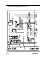
1
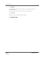
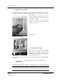
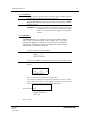
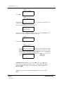
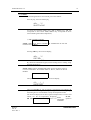
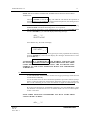
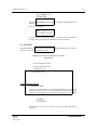
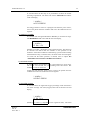
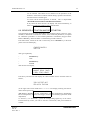
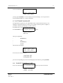
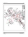
GUIDO RAYOS X, S.A.
MAN-011
Feb. 01
Ed. 2 / Rev. 1
1
NESTORET 5050
GUIDO RAYOS X, S.A.
2
INDEX
Disclaimer
I
Description
7
I.1
Hood
7
I.2
Humidity system
7
I.3
Fitler unit
7
I.4
Cabinet
8
I.5
Stand
8
Operation
9
II.1
Humidity control
9
II.2
Oxygen system
9
II.3
Front panel (Description and functions)
11
II.4
Heating pack
13
A
To operate
13
B
To preheat
13
C
To heat
15
II
D
II.5
A
B
II.6
MAN-011
Feb. 01
Ed. 2 / Rev. 1
1 Air control mode
15
2 Servo control mode
16
Oxygen and relative humidity
17
Alarms
19
Air control mode
19
1 Sensor alarm
19
2 Low temperature alarm
20
3 High temperature
20
Servo control mode
20
1 Sensor alarm
20
2 Low temperature
21
3 High temperature
21
C
Power failure
22
D
Fan failure (Air circulation)
22
E
Humidity alarm
22
F
Heating alarm
22
G
Oxygen alarm
22
Sensors activation and deactivation
23
NESTORET 5050
GUIDO RAYOS X, S.A.
3
II.7
Software language
24
II.8
Change of display type
25
II.9
ON/OFF Switch (SW) activation
25
II.10
Change of temperatura alarm range (High / Low)
25
Maintenance
26
III.1
Cabinet
26
III.2
Filter
26
III.3
Hood
26
III.4
Bed tray
27
III.5
Body
27
III.6
Battery from power failure alarm
27
Service
28
Electronic circuitry
28
Main mode
29
1 Power supply
29
2 Microcontroller
29
3 A/D Converter and Multiplexer
30
4 Sensors
30
5 Power drivers
31
III
IV
IV.1
A
IV.2
IV.3
Adjustments
31
A
Air temperature
32
B
Patient temperature
32
C
Oxygen concentration
33
D
Heating indication
33
E
Relative Humidity
34
F
Security Thermostat
34
Wiring diagrams, Spare parts list
35
Warranty
MAN-011
Feb. 01
Ed. 2 / Rev. 1
NESTORET 5050
GUIDO RAYOS X, S.A.
MAN-011
Feb. 01
Ed. 2 / Rev. 1
4
NESTORET 5050
GUIDO RAYOS X, S.A.
5
DISCLAIMER
The safety devices and other controls provided in this equipment will perform reliably
when operated, maintained, and repaired in accordance with the instructions of this
manual.
Safety devices must be checked periodically and reset, repaired, or replaced as
necessary to ensure that they will operate reliably. Equipment and parts that are broken,
missing, badly worn, distorted or contaminated should be replaced with appropriate
GUIDO RAYOS X parts. The equipment or its components should not be modified
without the approval of the manufacturer.
The Manufacturer disclaims all responsability for any malfunction of this equipment
resulting from faulty operation, maintenance or repair, or if any of its components are
damaged or modified by anyone other than the manufacturer.
MAN-011
Feb. 01
Ed. 2 / Rev. 1
NESTORET 5050
GUIDO RAYOS X, S.A.
MAN-011
Feb. 01
Ed. 2 / Rev. 1
6
NESTORET 5050
GUIDO RAYOS X, S.A.
7
I. DESCRIPTION
The NESTORET Incubators are designed for the hospital where isolation of the
newborn is a prime objective. All surfaces are easily accessible for cleaning.
The incubator consists of a transparent hood mounted on a body unit wich contains a
heating pack, a heat circulation system, a humidity system, an air filter unit and an
infant bed wich is adjustable for Trendelenburg, Fowler and Examination positions.
With the front door open, the bed slides out for examination procedures without
becoming disengaged or falling. For such purpose, place the bed on up position by
rotating backwards the two tilting knobs located at both sides of the Incubator base,
then slides the bed out gently until it stops, its security design will avoid to fall.
A cabinet, mounted on casters and having storage space for accessories (except the
BASIC Version), supports the incubator. The incubator includes an I.V. stand.
I.1 HOOD
Transparent, incorporates six hand hole ports, thermometer and a front opening door.
The six hand hole ports have soft
selfadjusting plastic sleeves (optional)
wich are protected from room
contamination by elbow opening clear
molded doors.
The fold-down front door permits
maximum access to the infant when inhood procedures are required.
I.2 HUMIDITY SYSTEM
The humidity system consists of a "Water Fill & Drain" unit, a humidity control knob,
a water reservoir, and a connecting rubber tube.
The "Water Fill & Drain" unit, which is mounted in the left side of the incubator, is
made of translucent plastic so the water level in the incubator is visible at all times.
The humidity control knob is mounted on the left side of the incubator.
The rubber tubing in the humidity system is made of silicone rubber and is autoclavable.
The humidity reservoir and cover are easily removed from the incubator, and can be
autoclaved.
I.3 FILTER UNIT
The filter unit consists of filter pads, cover and oxygen inlets.
The filter housing incorporates the 35% oxygen limiting inlet.
The filter consists of three pads and will remove all air-borne particles.
The cover enables the operator to visually inspect the filter.
MAN-011
Feb. 01
Ed. 2 / Rev. 1
NESTORET 5050
GUIDO RAYOS X, S.A.
8
I.4 CABINET
Its compartments enables the storage of accessories, etc. Only the BASIC Version has
no storage capability.
Foot brakes are provided on the two front casters in order to lock the wheels.
I.5 IV STAND
Mounted at the left on the rear side, its height is adjustable.
II. OPERATION
MAN-011
Feb. 01
Ed. 2 / Rev. 1
NESTORET 5050
GUIDO RAYOS X, S.A.
9
II.1 HUMIDITY CONTROL
The humidity control system provides a range of humidities from closed (-) to open (+).
Humidity condensate will depend on the difference in room temperature and incubator
temperature.
Fill to the gauge line (1.2 liters aprox). Set the
humidity control knob to the desired position.
Check water level daily.
To drain the reservoir, pull and, without
pulling, turn right the manifold and drain the
water into a container.
1. Water level.
2. Humidity control knob.
1
2
II.2 OXYGEN SYSTEM
There are two inlets provided for controlled
administration of oxygen. A 35% oxygen
limiting inlet and the Up to 100% inlet are
supplied with metal screw-on caps. Both inlets
are located on the filter unit.
Oxygen should be administered using a "BACK PRESSURE COMPENSATED"
flowmeter.
IMPORTANT:
ROUTINELY
CHECK THE OXYGEN CONCENTRATION IN
THE INCUBATOR.
Tubing from the flowmeter should be connected to the 35% inlet nipple when the
oxygen concentration in the incubator is to be limited to 35%. The 35% inlet will limit
the oxygen concentration in the incubator regardless of the flow. For a fast increase of
the oxygen concentration (up to 35%) in the incubator, flows as high as 20 to 30 l.p.m.
can be used; however, for economy of operation and to obtain concentrations in the
MAN-011
Feb. 01
Ed. 2 / Rev. 1
NESTORET 5050
GUIDO RAYOS X, S.A.
10
35% range, a flow of 3 l.p.m. is recommended.
When oxygen concentrations above 35% are
required, the tubing from the flowmeter should be
connected to the Up to 100% inlet and the 35% inlet
should be capped. Oxygen administered through this
inlet will produce concentrations in the incubator of
from 40 to Up to 100% depending on the rate of
flow. Oxygen concentrations should be checked and
the flow of oxygen increased or decreased until the
desired concentration has been reached.
When high oxygen concentrations are required, the
following steps should be taken:
The water reservoir should be filled with water to
the fill line.
•
•
Air filters should be clean.
•
the vents on the sides of the hood should be closed.
CAUTION: DO NOT USE CONVENTIONAL OILS AND
GREASES IN OXYGEN SERVICE EQUIPMENT BECAUSE OF
POTENTIAL FIRE HAZARD.
USE SPECIAL OXYGEN
SERVICE LUBRICANT.
WARNING: OXYGEN CONCENTRATIONS
HIGHER THAN
40%
CAN INCREASE
THE RISK OF RETROLENTAL FIBROPLASIA (RETINOPATHY OF PREMATURITY).
IS PROBABLE THAT EVEN CONCENTRATIONS OF
40%
OXYGEN
IT
(FORMERLY
CONSIDERED SAFE) COULD BE DANGEROUS FOR SOME INFANTS.
FLOW SETTING:
Set the flow at the approximate concentration rates stated here below
II.3 FRONT PANEL (DESCRIPTION AND FUNCTIONS)
II.4. HEATING PACK.
3 LPM
for concentration of 40 - 50%
5 LPM
for concentration of 55 - 65%
10 L P M
for concentration of 75 - 85%
IMPORTANT: BEFORE
MAN-011
Feb. 01
Ed. 2 / Rev. 1
USING THE
INCUBATOR
WITH A PATIENT, IT IS
NESTORET 5050
GUIDO RAYOS X, S.A.
11
NECCESSARY TO CHECK ITS GOOD PERFORMANCE CONDITIONS, AS WELL AS
THOSE FROM THE ACCESSORIES AND OPTIONS.
(1)
(2)
(3)
HEAT/CALOR
Indication of heating device operation
ON/OFF
Heating control switch
LCD
Display information, messages, etc.
SERVO
Patient Temperature operation mode
AIR
Air temperature operation mode
STAR/STOP
Start/Stop operation
1...0
Numerical sensitive keypad
ENTER
Confirm the set values
PRE
Preheating
O2/HUM
Select Oxygen or Relative Humidity readout
HIGH/ALTA
High Temperature alarm
LOW/BAJA
Low Temperature alarm
SENSOR
Sensor failure alarm
MOTOR
Air Circulation alarm
POWER/ALIM.
Power failure alarm
HUMIDITY /
HUMEDAD
High or Low Relative Humidity alarm
% O2
Hihg or Low Oxygen alarm
Silence alarms
MAN-011
Feb. 01
Ed. 2 / Rev. 1
NESTORET 5050
GUIDO RAYOS X, S.A.
MAN-011
Feb. 01
Ed. 2 / Rev. 1
12
NESTORET 5050
GUIDO RAYOS X, S.A.
13
A. TO OPERATE:
To start operation, plug the unit to the mains (check voltage) and press
the I/O switch located at the right side of the trolley.
Press the ON/OFF key at the front panel, the LCD will display "GUIDO
RAYOS X", immediately afterwards the Incubator will perform a selftest
of all its circuitry.
IMPORTANT: When the Incubator is operated for the first time when
its installation, it is neccessary to calibrate the Oxygen
sensor as it is described at the page 18 in the present
Manual.
B. TO PREHEAT:
CAUTION:BEFORE TO USE THE INCUBATOR WITH THE NEWBORN,
PREHEAT
THE UNIT FOR A BETTER COMFORT OF THE NEWBORN AND AN ACCURATE
PERFORMANCE.
PREHEATING
PERIOD OF TIME DEPENDS ON ENVIRONMENTAL
TEMPERATURE. IF PREHEATING MODE IS NOT DESIRED, THE OPERATION MODE,
AIR OR SERVO, CAN BE DIRECTLY SELECTED.
Pressing any key the LCD will display,
AIR=__._ ºC
SELECT MODE
Press the key “PRE” to start the preheating until to reach aproximately
the factory preset temperature (28 ºC). In the meantime the LCD will
display
AT=__._ ºC (__._ ºC)
PREHEATING
After “=“ symbol we can find present temperature.
It is possible to modify preset preheating temperature in order to reach a
nearly temperature of the normal operation temperature. Proceed with
following steps to change preset preheating temperature:
•
Turn on the incubator:
GUIDO RAYOS X
VER X.X
•
MAN-011
Feb. 01
Ed. 2 / Rev. 1
Press any key :
NESTORET 5050
GUIDO RAYOS X, S.A.
14
AIR=__._ ºC
SELECT MODE
•
Press AIR ,
AIR=__._ ºC
PSET AIR=28.0 ºC
•
Change old preset 28.0ºC temperature to new preheating temperature with
numerical keypad.
•
By pressing ENTER, you will confirm selection ,
AT=__._ ºC
PRESS START
•
Despite it is displayed “PRESS START”, you have to press “ENTER”. This is
because this is an special feature of NESTORET 5050 .
AIR=__._ ºC
SELECT MODE
•
Finally, press PRE. ,
AT=__._ ºC (__._)
PREHEATING
Once the preheating temperature is reached, the LCD will display "UNIT
READY", to be used within a patient, displaying the temperature inside
the Incubator as well as advising to the medical personnel by means of an
acoustic signal. Then the Operation Mode
should
be selected just afterwards the newborn is New
placed
temperature
into the Incubator.
in brackets
IMPORTANT:BY
PRE. KEY, THE LCD WILL
AIR TEMPERATURE (AT),
PERCENTAGE (OX) AND RELATIVE
PRESSING AGAIN THE
DISPLAY THE REGISTERED PARAMETERS, SUCH AS
PATIENT TEMPERATURE (ST), OXYGEN
HUMIDITY (RH).
NOTE: TO
II.4.4.
MAN-011
Feb. 01
Ed. 2 / Rev. 1
SET
OXYGEN
AND
RELATIVE HUMIDITY
VALUES, SEE CHAPTER
NESTORET 5050
GUIDO RAYOS X, S.A.
15
C. TO HEAT
If Preheating Mode was not selected, proceed as follows:
Press any key, the LCD will display,
AIR=__._ ºC
SELECT MODE
To select the Operation Mode press AIR or SERVO key. AIR key
corresponds to Air Control Mode; SERVO key corresponds to Servo
Control Mode (patient skin temperature).
1) AIR CONTROL MODE:
NOTE: THE
DIGITAL DISPLAY INFORMS THE TEMPERATURE OF THE AIR
FLOWING INTO THE HOOD.
Pressing AIR key, the LCD will display ,
AIR=__._ ºC
PSET AIR=__._
By means the numerical keypad, set the heating device working range
between 20 and 40 ºC.
NOTE: WHEN
SETTING TEMPERATURE ENTER ALWAYS
CASE OF NO DECIMALS.
AS
EXAMPLE PRESS
3,
THEN
7,
3
DIGITS, EVEN IN
THEN
0
TO SET
37
DEGRESS.
Then press ENTER to confirm, the LCD will display ,
AT=__._ (__._)
PRESS START
Then press START to start the heating. The LED bar will indicate the
operation of the heating device. By reaching the selected heating range,
the heating devices will modulate to keep the temperature stable.
The LCD will display the air flow registered temperature, as well as will
inform, too, the set temperature, displaying
ACTIV
ED UNIT to inform the heating device is in Preset
operation
temperature
.
in brackets
MAN-011
Feb. 01
Ed. 2 / Rev. 1
NESTORET 5050
GUIDO RAYOS X, S.A.
16
AT=__._ ºC (__._)
UNIT ACTIVE
The selected heating range can be modified at any time by pressing
START/STOP and after ENTER key; you will find displayed following
message :
AIR=__._ ºC
SELECT MODE
Then set the new temperature by the keypad as previously explained and
confirm by pressing ENTER key. The LCD will display the messages
described above. Then press START key.
2) SERVO CONTROL MODE:
ATTENTION:BEFORE SELECTING SERVO CONTROL MODE
PROCEED TO PREHEAT THE INCUBATOR AS EXPLAINED
PREVIOUSLY IN THE II.4.2. TO PREHEAT CHAPTER.
Before anything display on the screen following message :
AIR=__._ ºC
SELECT MODE
Press SERVO key, the LCD will display ,
SKIN=__._ ºC
PSET SKIN=__._
Set the patient temperature between 20 and 40 ºC by means of the
keypad, confirm by pressing ENTER key.
NOTE: WHEN
SETTING TEMPERATURE ENTER ALWAYS
CASE OF NO DECIMALS.
AS
EXAMPLE PRESS
3,
THEN
7,
3
DIGITS, EVEN IN
THEN
0
TO SET
37
DEGRESS.
The LCD will display ,
ST=__._ ºC (__._)
PRESS START
MAN-011
Feb. 01
Ed. 2 / Rev. 1
NESTORET 5050
GUIDO RAYOS X, S.A.
17
NOTE: ST
MEANS PRESENT TEMPERATURE.
TEMPERATURE IN BRACKETS MEANS PRESET
TEMPERATURE.
Then press START to start the heating. The LED bar will indicate the operation of
the heating devices. By reaching the selected patient temperature, the heating devices
will modulate to keep the temperature stable.
The LCD will inform the patient temperature and the selected one. By displaying
UNIT ACTIVE will inform the heating device is on operation.
The set patient temperature can be modified at any time by pressing START/STOP
and after ENTER key; you will find displayed following message :
AIR=__._ ºC
SELECT MODE
Press SERVO key, the LCD will display
SKIN = __._ ºC
PSET SKIN = __._ ºC
Then set the new temperature by the keypad as previously explained and confirm by
pressing ENTER key. The LCD will display the messages described above. Then
press START key.
ATTENTION: IF A MOMENTARY PAUSE WITHOUT CHANGING THE
SET PATIENT TEMPERATURE IS REQUIRED, PRESS STOP KEY. PRESS
START KEY TO CONTINUE OPERATION. THE INCUBATOR WILL
OPERATE ON THE SAME OPERATION MODE AND PARAMETERS
ALREADY SET.
D. OXYGEN AND RELATIVE HUMIDITY
A) The NESTORET 5050 Incubator monitors the Oxygen percentage inside the hood
and the Relative Humidity.
To set the alarm levels for above mentioned parameters proceed as follows (always
before to place the infant into the Incubator and before to deliver any oxygen flow,
due to when calibrating at 21% if the concentration is higher the calibration got will
be erroneus).
B) To see in the LCD the O2 and humidity parameters, press the O2/HUM key when
the incubator is activated in the servo or manual mode ever since no alarm optical/
acustic is activated
NOTE: WHEN SELECTING PARAMETERS YOU MUST START FROM
“SELECT MODE” SCREEN :
AIR=__._ ºC
MAN-011
Feb. 01
Ed. 2 / Rev. 1
NESTORET 5050
GUIDO RAYOS X, S.A.
18
SELECT MODE
Press the O2/HUM key, the LCD will display ,
AIR=__._ ºC
1=OXYG, 2=HUMID
To set the Oxygen range press 1, the LCD will display
AIR=__._ ºC
OX: 1=PRG, 2=CAL
Then, press 1 again ,
AT=__._ ºC (__._)
PRESET OX %=21.0
By means of the keypad set the desired value. Press ENTER key to confirm.
Once again you will find following screen :
AIR=__._ ºC
1=OXYG, 2=HUMID
Real oxygen
percentage in
brackets
Finally press ENTER to confirm values.
To calibrate the Oxygen Sensor, press the O2/HUM. key, the LCD will display ;
AIR=__._ ºC
1=OXYG, 2=HUMID
NOTE:
DUE TO THE WEAR OF THE OXYGEN CELL SENSOR IT IS RECOMMENDED TO
PERFORM PERIODICALLY ITS CALIBRATION PROCEDURES
Check the Oxygen Sensor is pluged on the front panel and its housing is not located
inside the Hood, allow to stabilize.
Press 1, the LCD will display,
AIR=__._ ºC
OX: 1=PRG, 2=CAL
Press 2, the LCD will display ,
MAN-011
Feb. 01
Ed. 2 / Rev. 1
NESTORET 5050
GUIDO RAYOS X, S.A.
19
OX CALIBR (21 %)
PRESS ENTER
By pressing ENTER, the Oxygen Sensor is already calibrated with a new
reference.
New screen displayed ;
AIR=__._ ºC
OX: 1=PRG, 2=CAL
To set the Relative Humidity procedure is the same we have explained to
Oxygen values, but selecting 2=HUMID, instead of 1=OXYG.
II.5. ALARMS
The NESTORET 5050 Alarm System informs to the medical attendant of any incidence
may occur. The alarm is visible and audible.
NOMENCLATURE OF SYMBOLS IN ALARM
MESSAGES
+ Excess temperature alarm
-
Failing temperature alarm
= Temperautre O.K.
* Desactive sensor
A) AIR CONTROL MODE
1. SENSOR ALARM:
In case of air sensor failure or it gets disconnected or out of range; the
SENSOR Alarm will activate the corresponding LED and buzzer, the
alarm cannot be silenced. The LCD will inform to the attendant
displaying ,
* ALARM *
AIR SENSOR
The Incubator is now out of service. Call to any authorized Service
engineer.
MAN-011
Feb. 01
Ed. 2 / Rev. 1
NESTORET 5050
GUIDO RAYOS X, S.A.
20
2. LOW TEMPERATURE ALARM:
Is activated when temperature reaches aproximately 1 ºC below the preset
temperature (See paragrap II.10 to cahnge preset temperature alarm
range). "LOW" alarm LED will lit, to silence acoustic alarm press
SILENCE key. The LCD will display
* ALARM *
AT - RH OX
The alarm can be silenced by pressing the SILENCE key. If SILENCE
was pressed and the alarm conditions remain during a period of ten
minutes, the alarm will be activated again.
IMPORTANT:CHECK THE
CHECK
HOLE DOORS, HOOD AND TUBING PORTS ARE
PROPERLY CLOSED.
THE
HEAT LED
BAR IS LITTING
(THE
MICROPROCESSOR CONTROLS THE HEATING DEVICE); IF CONTRARY, UNPLUG
THE UNIT FROM THE POWER SOURCE, REMOVE THE PATIENT
INCUBATOR AND CALL TO THE AUTHORISED SERVICE ENGINEER.
FROM THE
3. HIGH TEMPERATURE
Is activated when the temperature reaches aproximately 1 ºC higher than
the preset temperature (See paragrap II.10 to cahnge preset temperature
alarm range). "HIGH" alarm LED will lit and the LCD will display ,
* ALARM *
AT + RH OX
to silence acoustic alarm press SILENCE key.
Check if heat sources are close to the Incubator location, if positive keep
them away. If the alarm is still effective unplug the unit from the power
source, remove the patient from the incubator and call to the authorised
service engineer.
B) SERVO CONTROL MODE
1. SENSOR ALARM:
Informs when a failure of the skin probe or if it gets disconnected or out
of range. The Alarm will activate the corresponding LED and buzzer.
The LCD will display ,
* ALARM *
SKIN SENSOR
MAN-011
Feb. 01
Ed. 2 / Rev. 1
NESTORET 5050
GUIDO RAYOS X, S.A.
21
being possible to silence. The Incubator is now out of service. It can be
used on Air Mode if no any circunstances or alarms avoid it, in case it is
absolutely needed switch to Air Operation Mode and call to the
authorized service engineer.
2. LOW TEMPERATURE
Is activated when temperature reaches aproximately 1 ºC below the preset
temperature (See paragrap II.10 to cahnge preset temperature alarm
range). "LOW" alarm LED will lit and the LCD will display,
* ALARM *
ST - RH OX
to silence acoustic alarm press SILENCE key. If SILENCE was pressed
and the alarm conditions remain during a period of ten minutes, the alarm
will be activated again.
IMPORTANT:CHECK THE CONDITIONS OF THE PATIENT. CHECK THE HOLE
CHECK THE HEAT
LED BAR IS ON (THE MICROPROCESSOR CONTROLS THE HEATING DEVICES); IF
CONTRARY, UNPLUG THE UNIT FROM THE POWER SOURCE, REMOVE THE
PATIENT FROM THE INCUBATOR AND CALL TO THE AUTHORISED SERVICE
ENGINEER.
DOORS, HOOD AND TUBING PORTS ARE PROPERLY CLOSED.
3. HIGH TEMPERATURE
Is activated when the temperature reaches aproximately 1 ºC higher than
the preset temperature (See paragrap II.10 to cahnge preset temperature
alarm range). "HIGH" alarm LED will lit and the LCD will display ,
* ALARM *
ST + RH OX
to silence acoustic alarm press SILENCE key. HEAT LED will switch
off.
Check the conditions of the patient. Check if heat sources are close to the
Incubator location, if positive keep them away.
If the alarm is still effective, unplug the unit from the power source,
remove the patient from the incubator and call to the authorised service
engineer.
C) POWER FAILURE
Is activated when failure of the power from the battery or from the mains.
The alarm circuit includes a rechargeable battery and operation
conditions of it must be checked periodically.
D) FAN FAILURE (AIR CIRCULATION)
MAN-011
Feb. 01
Ed. 2 / Rev. 1
NESTORET 5050
GUIDO RAYOS X, S.A.
22
Is activated when the fan stops or its performance is below the normal
operating requirements. The alarm will activate MOTOR LED and the
LCD will display ,
* ALARM *
MOTOR ERROR
not being possible to silence it. Unplug the unit from the power source,
remove the patient from the incubator and call to the authorised service
engineer.
E) HUMIDITY ALARM.
Is activated when the registered Relative Humidity is out of the set range.
The HUMIDITY LED will lit and the LCD will display ,
* ALARM *
ST RH ± OX
(HIGH(+) or LOW(-), depending on the registered value). The alarm can
be silenced. This alarm does not interfere on the operation of the
Incubator. If the alarm conditions remain during a period without turning
off the SILENCE key, ten minutes later, the alarm will be activated again.
To switch off the alarm operation, if desired, refer to chapter II.6
"SENSORS ACTIVATION AND DEACTIVATION".
F) HEATING ALARM.
Is activated when correspondent sensor is disconnected or out of range.
The Alarm will activate the corresponding LED and buzzer. The
Incubator is now out of service.
Unplug the unit from the power source, remove the patient from the
incubator and call to the authorised service engineer.
* ALARM *
HEATING ERROR
G) OXYGEN ALARM.
Is activated when the registered Oxygen percentage inside the Hood is
out of the set range. The %02 (Oxygen) LED will lit and the LCD will
display ,
* ALARM *
ST RH OX ±
(HIGH (+) or LOW (-), depending on the registered value). The alarm
MAN-011
Feb. 01
Ed. 2 / Rev. 1
NESTORET 5050
GUIDO RAYOS X, S.A.
23
can be silenced. This alarm do not interfere on the operation of the
Incubator. If the alarm conditions remain during a period of ten minutes,
the alarm will be activated again.
To switch off the alarm operation, if desired, refer to chapter II.6.
"SENSORS ACTIVATION AND DEACTIVATION".
If any alarm has been silenced the display will work intermitently, in
order to see better the situation of the silenced alarm.
II.6. SENSORS ACTIVATION AND DEACTIVATION
The applications program of the NESTORET 5050 Incubator allows to the user, at any
moment, to deactivate or activate the sensors of the monitored parameters, if required
for calibration procedures or non essential parameters cancellation (Oxygen and/or
Relative Humidity). If the Incubator is switched off, proceed as follows:
Press I/O switch, located at the side of the trolley. Press ON/OFF key at the front
panel. The LCD will display ,
GUIDO RAYOS X
VER X.X
then type sequentially:
•
SILENCE key
•
7388
•
SILENCE key.
ENTER
then the LCD will display ,
•
MAINT: 0 SW, 1 LNG
2 SEN, 3 DIS, 4 RNG
Press 2 key and the LCD will display all coded available sensors and their status as
follows,
1RH 2AT 3ST 4HT
5FA 6OX 7A2 8AI
(at the right side of each coded sensor "+" or "-" will display, meaning activated or
deactivated respectively)
(RH=Relative Humidity, AT=Air Temperature, ST=Skin Temperature, HT=Heating
Device Temperature, FA=Fan, OX=Oxygen, A2 and A1 are auxiliary options for future
implements)
To activate (+) or deactivate (-) press the corresponding figure key of the sensor.
Proceed with any sensor you want to activate or deactivate, then press ENTER to
confirm.
MAN-011
Feb. 01
Ed. 2 / Rev. 1
NESTORET 5050
GUIDO RAYOS X, S.A.
24
The LCD will display ,
MAINT.: 0 SW, 1 LNG
2 SEN, 3 DIS, 4 RNG
pressing again ENTER the LCD will display the initial message. You can proceed to
set the Operation Mode, etc. as above described.
II.7. SOFTWARE LANGUAGE
The applications program of your NESTORET 5050 is delivered from factory in two
languages: english and spanish. At factory your incubator has been preset to english, if
you want to switch to the language, proceed as follows:
Press I/O switch, located at the side of the trolley.
Press ON/OFF key at the front panel. The LCD will display ,
GUIDO RAYOS X
VER X.X
then type sequentially:
•
SILENCE key
•
7388
•
SILENCE key.
ENTER
then the LCD will display,
•
MAINT.: 0 SW, 1 LNG
2 SEN, 3 DIS, 4 RNG
Press 1 key the LCD will display ,
1=ENGLISH VER
2=SPANISH VER
press the corresponding key to the selected language and confirm by pressing ENTER.
II.8. CHANGE OF DISPLAY TYPE
Press 3 key when applications programm is selected, display type will be activated,
1 DISPL 16 CARS
2 DISPL 20 CARS
MAN-011
Feb. 01
Ed. 2 / Rev. 1
NESTORET 5050
GUIDO RAYOS X, S.A.
25
for LCD equipment press 1; for luminiscent display press 2.
II.9. ON/OFF SWITCH (SW) ACTIVATION
Press 0 key when applications programm is selected. The display will show:
WITH ON/OFF
WITHOUT ON/OFF
For equipments with ON/OFF switch on front panel keypad, press the ON/OFF key,
selecting WITH ON/OFF option.
II.10. CHANGE OF TEMPERATURE ALARM RANGE (HIGH /
LOW)
Press 4 key when applications programm is selected. The display will show:
RNG.TMP (0.1 ÷ 2.0)
R= __._ , H=
Preset value of temperature Range (R) (High / low) is 1 ºC. To this value corresponds a
hysteriris value (H) of 0,4 ºC.
To change the preset value (R) (between 0,1 ºC and 2,0 ºC), by means of the numerical
keypad, set the required value and press ENTER, the display will show the
corresponding hysteresis value (this value H can not be changed).
Then press ENTER again to accept the new values (R) and (H).
those used in window washing) and to smaller areas with a clean, soft
cloth, sponge, or chamois. DON'T use boiling water. DON'T use strong
solvents such as ether.
Drying
If it is necessary to dry the washed surface, use a clean damp
chamois. DON'T rub hood with a dry cloth.
III.4 BED TRAY
The bed tray can be autoclaved at 15 p.s.i. (1.05 kg/cm2) for 20 minutes. It must be
laid upside-down on a flat surface during sterilization to prevent distortion.
MAN-011
Feb. 01
Ed. 2 / Rev. 1
NESTORET 5050
GUIDO RAYOS X, S.A.
26
III. MAINTENANCE
III.1 CABINET
The cabinet can be cleaned with a damp cloth and soap. It must be dried immediately
afterwards.
III.2 FILTER
The filter should be replaced every three
months. Pull gently from the Up to 100%
Oxygen inlet and press it gently towards
the Incubator side until the panel can be
removed. Remove the filter pads and
replace with the new ones. Replace the
panel and apply the self-adhesive tab
(from the filter instruction sheet) to the
face of the panel. Note the date of replacement of the filter pads on the tab.
III.3 HOOD
The hood can be removed from the body loosening the four thumb screws which hold
the bed spacers in place. Loosen the thumb screws, disengage the bed spacers from the
hood, disengage the two screws from the sensor housing and carefully remove the hood.
ATTENTION:
BEFORE PROCEEDING, UNPLUG THE TEMPERATURE AND
AIR/HUMIDITY SENSORS ASSEMBLY LOCATED AT THE LEFT SIDE OF THE HOOD.
ONCE CLEANED, PLUG IT AGAIN.
The hand hole doors can be replaced by unscrewing the hinge pin and removing the
door.
The hood can be cleaned with soap and water. Accepted desinfectants such as
Wescodyne, Warexin, etc., may be used. NEVER use ether, alcohol or acetone to clean
the hood.
Dusting
Dust and clean hood with a soft, damp cloth or chamois. Wipe the
surface gently. DON'T use gritty cloths.
Washing
Wash with mild soap or detergent and water. DON'T use scouring
compounds.
Use plenty of water. Apply to large areas with a bristle mop (such as
MAN-011
Feb. 01
Ed. 2 / Rev. 1
NESTORET 5050
GUIDO RAYOS X, S.A.
27
III.5 BODY
It is double walled. The outer wall is made of High Impact ABS, the inner wall is made
of aluminium with epoxy painting.
When all removable components of the incubator have been taken out, the body may be
cleaned with soap and water and may be desinfected using a commercially available
cold sterilizing solution. Be sure to use a solution that does not affect to the painting.
CAUTION: DO NOT USE ANY CLEANING AGENT CONTAINING ABRASIVE
MATERIALS. HOT CAUSTICS, HIGHLY CHLORINATED SOLVENT, OR ANY AGENT
CONTAINING IODINE FULL STRENGTH SHOULD BE AVOIDED AS DISFIGURATION
OF THE EPOXY COATED ENAMEL COULD RESULT.
DO NOT GAS OR STEAM STERILIZE THE BODY.GAS AND STEAM
STERILIZATION TECHNIQUE COULD CAUSE BLISTERING OF THE EPOXY FINISH
AND OF THE HIGH RESISTANT ABS OUTER WALL.
III.6. BATTERY FROM POWER FAILURE ALARM
CAUTION : CHECK PERIODICALLY THE BATTERY FROM THE POWER FAILURE
ALARM.
To perform it, just unplug the cord from the mains meanwhile the Incubator is under
operation (the alarm will activate the corresponding Power alarm LED and the buzzer).
IMPORTANT: THE NESTORET 5050 INCUBATOR INCLUDES THE MOST
ADVANCED ELECTRONIC DESIGN, INSURING GREATER RELIABILITY IN ITS
OPERATION. ANY TECHNICAL SERVICE PERFORMED IN ITS MAINTENANCE
REQUIRES PROPERLY TRAINED, QUALIFIED PERSONNEL.
A).- MAIN MODULE
For a better explanation and understanding, the Main Module has been
clasified in the following blocks:
•
Power Supply
•
Microcontroller
•
A/D Converter and Multiplexer
•
Sensors
MAN-011
Feb. 01
Ed. 2 / Rev. 1
NESTORET 5050
GUIDO RAYOS X, S.A.
28
IV. SERVICE.
Service must be performed by qualified and authorized service personnel. Call to the
manufacturer or its Agent for any service you may require.
To accede to the heating module and/or to the printed board it is neccessary to open the
Incubator Base front.
Proceed as follows:
•
Unscrew the small screws from the front lower part at both sides of the Incubator
Base.
•
From inside the Hood, unscrew the front screws from the hinges located on the
lower corner of the Hood sides. The other two screws located besides the above
ones must be slightly loosen.
•
Pull gently upwards the front door. The pins of the hinges will get out from the
Base.
Pull outwards from both ends the whole front Base. The front will tilt leaving the
access free.
In case to need more free access to replace any part on the heating module proceed as
follows:
•
IMPORTANT: BEFORE TO PROCEED AS DESCRIBED BELOW, SWITCH OFF THE INCUBATOR POWER SUPPLY
(RIGHT SIDE ON THE TROLLEY) AND UNPLUG THE CORD
FROM THE MAINS.
Unplug the wiring multiconnector from the printed board. Check the ground wire is also
out from the screw on the heating module.
IMPORTANT: BE SURE TO UNPLUG FROM THE MULTICONNECTOR THE TWO
LABEBED WIRES OF THE BLACK CABLE FROM THE POWER SUPPLY.
Unscrew the four nuts that hold the heating module into its location. You can now to
withdraw it carefully. Proceed by pulling it outwards from its location and turning it
gradually, facing to the top.
ATTENTION: WHEN
ABOVE PROCEDURES, TAKE CARE NOT TO DISCONNECT
ACCIDENTALLY ANY WIRE, ETC.
IF IT HAPPENS PROCEED
TO SOLVE IT ACCOR-
DING TO THE WIRING DIAGRAM.
IV. 1. ELECTRONIC CIRCUITS
The following describes the electronic operation of the 5050 module and includes
electronic schematics, adjustments guide and instructions for proper technical maintenance.
MAN-011
Feb. 01
Ed. 2 / Rev. 1
NESTORET 5050
GUIDO RAYOS X, S.A.
•
29
Power Drivers
1. Power Supply
Tension from Transformer (15-0-15 V AC) is rectified by the PR1 diodes
bridge. +5 Vcc power is got by means of the RE2 (7805) Tension
Regulator and its filters. The R74 Resistor dissipates the generated power
when a power fall to the input of the RE2 Regulator.
+15 Vcc power is got by means of the RE3 (7815) Tension Regulator
and its filters.
-15 Vcc power is got by means of the RE4 (7915) Tension Regulator and
its filters.
2. Microcontroller
A DALLAS DS5000 Microcontroller checks and controls all Incubator
functions. An Oscillator/Clock circuit composed by X1, C9 and C10
generates a 12 MHz frecuency.
The Microcontroller reads the keypad via the U2 Keypad Decodifier.
Any time a key is pressed, the Decodifier transfer the data to the
Microcontroller which collects the information of the event by the INT0
interruption. Besides, it transfers a signal to the buzzer, generating an
acoustic signal any time a key is pressed.
A Microcontroller function is to display the data on the J6 LCD, as well
as to activate the alarm LED's L2 ... L8. Also it activates the ARL1
LED's bar to indicate the heat output generation. U10 and U15 Integrated
Circuits are latches of those signals being reloaded each 10 ms.
The Microcontroller collects periodically the data from all the sensors
from the A/D U11 Converter.
3. A/D Converter and Multiplexer
All signals generated by the sensors are multiplexed by the U12 that, up
on requirement of the Microcontroller, will write the data to the sensor
multiplexer to be converted into digital. At present six of the eight
Multiplexer inputs are used being the J11 and J12 connectors free for
future implements.
That signal at the Multiplexer output is drived to the eight bits A/D U11
Converter. It converts the input analogic data and performs its conversion
into digital at its data output, being readed by the Microcontroller that
performs the conversion from digital data into the displayed values
(Temperature, % Humidity, % Oxygen, etc.). The TP5 reference voltage
and the TP3 offset are respectively adjustable by the P6 and P9
potentiometers.
4. Sensors
MAN-011
Feb. 01
Ed. 2 / Rev. 1
NESTORET 5050
GUIDO RAYOS X, S.A.
30
The NESTORET 5050 Incubator has the capability to read signals
generated by an Air Temperature sensor, by a Skin Temperature sensor,
by a Humidity sensor, by an Oxygen Concentration sensor, by a Heating
Device Temperature sensor and the Fan Operation by HALL effect.
The Air Temperature Sensor is amplified by U7 being possible to adjust
the P5 gain and the P13 offset.
The Skin Temperature sensor is isolated from the circuit by means the U8
isolation amplifier that provides a 2500 Vpp isolation. At the output of
this amplifier the U9 circuit amplifies the sensor isolated signal being
possible to adjust the gain and offset by the P14 and P8 respectively.
The Humidity sensor is a capacitive sensor with signal conditioning. It
makes a correction in the relative humidity depending on the temperature.
The humidity correction factor can be adjust by the P1 potentiometer of
the humidity board. Gain level is adjustable by P2.
The signal generated by the Oxygen Concentration sensor is amplified by
U16, being possible to adjust the gain and offset by P12 and P7
respectively.
The Heating Device Temperature sensor is amplified by U13 being
possible to adjust the P10 gain and P11 offset.
When fan blades rotation, the HALL effect sensor generates a pulse.
Those pulses are integrated by C19, D8, R66 and C21, having at TP9 a
proportional power to the fan rotating speed.
The J11 and J12 Connectors are free to receive any other analogic signal
that could be used on future implements. At present these two inputs are
deactivated in the activation/deactivation panel from the service program.
5. Power Drivers
The heating device and the fan are activated by their corresponding
driver. The signal coming from the Microcontroller is isolated by the
OPT1-OPT2 Optocoupler that feeds the TRC1-TRC2 Triac supplying
power to the heater and to the fan. The heater is activated and deactivated
upon requirement of the system. The fan is activated/deactivated when
pressing ON/OFF key.
IV.2. ADJUSTMENTS
Here below are described the adjustment instructions to perform on the NESTORET
5050 in case of replacement of some of the components, such as sensors, circuits, etc.,
due to a failure.
To perform the adjustments properly the following instruments are required:
•
Digital Voltmeter (DVM).
•
Temperature and Oxygen Concentration Simulator (SIM50TO).
•
Humidity Concentration Simulator (SIM50HR).
MAN-011
Feb. 01
Ed. 2 / Rev. 1
NESTORET 5050
GUIDO RAYOS X, S.A.
31
Screwdriver.
To access the electronic circuits open the Incubator Base front as explained on this
Manual.
•
Turn on the Incubator by pressing the I/O Switch located at the right side of the trolley.
Before performing the adjustments check the power from the power supply. Here below
are detailed power referenced to ground (GND -TP11):
POWER
+ 5 Volts ± 5%
+ 15 Volts ± 5%
- 15 Volts ± 5%
TEST POINT
TP8
TP10
TP12
Once checked, perform the adjustment according to the instructions detailed here
below.
•
Put DVM probes between GND-TP11 and TP3. Twist P9 Potentiometer to read
0 Volts.
•
Put DVM probes between GND-TP11 and TP5. Twist P6 Potentiometer to read
1250 mVolts.
•
Deactivate sensors on the Service Menu.
Turn off the Incubator by pressing the I/O Switch located at the right side ofthe
trolley.
Release the connectors J7, J8, J9, J14.
Connect on above connectors the wires from the Temperature Simulator
(SIM50TO) as follows :
•
•
•
CABLE CONNECTOR
SIM1
J7
SIM2
J8
SIM3
J9
SIM4
J14
Set the jumper at J5 and take it off when you finish the adjustment.
Turn on the Incubator by pressing the I/O Switch located at the right side of the trolley.
•
Press the ON/OFF key.
Press three times the "PRE." key.
The LCD will display :
AT=00.0 PT=00.0
OX=00.0 RH=00.0
(AT: Air Temp., PT: Patient Temp., OX: Oxygen, RH: Humidity)
A. Air Temperature
MAN-011
Feb. 01
Ed. 2 / Rev. 1
NESTORET 5050
GUIDO RAYOS X, S.A.
32
•
Set Simulator switch at "0".
•
Set DVM probes between GND-TP11 and TP2. Twist P13 Potentiometer to
read between 2 to 4 mVolts.
•
Set Simulator switch at "40/99".
•
Twist P5 Potentiometer to read 40.0 ºC at the Air Temperature Display on the
Incubator Control.
•
Set Simulator switch at "18/21".
Twist P13 Potentiometer to read 18.0 ºC at the Air Temperature Display on the
Incubator Control.
Because adjustments are mutual interactive, therefore have to be repeated steps 3 and 6
until to get the correct value.
•
Then disconnect the temperature simulator and connect again the sensors connector. Set
a precision patron termometer inthe middle of the mattress, 10 cm height f. Select 37ªC
as working temperature and go back to PREHEATING display.
When the temperature is stabilizated check then the air temperature (AT) is the same
that shows the patron termometer. If not, adjust the potenciometer P5 till both
temperatures are the same.
B. Patient Temperature
•
Set Simulator switch at "0".
•
Set DVM probes between GND-TP11 and TP4. Twist P8 Potentiometer to read
between 2 to 4 mVolts.
•
Set Simulator switch at "40/99".
•
Twist P14 Potentiometer to read 40.0 ºC at the Skin Temperature Display on the
Incubator Control.
•
Set Simulator switch at "18/21".
Twist P8 Potentiometer to read 18.0 ºC at the Skin Temperature Display on the
Incubator Control.
Because adjustments are mutual interactive, therefore have to be repeated steps 3 and 6
until to get the correct value.
•
Then disconnect the temperature simulator and connect again the sensors connector. Set
a precision patron termometer and the patient temperature sensor in the middle of the
mattress, 10 cm height. Select 37ªC as working temperature and go back to
PREHEATING display.
When the temperature is stabilizated check then the patient temperature (ST) is the
same that shows the patron termometer. If not, adjust the potenciometer P14 till both
temperatures are the same.
C. Oxygen Concentration
•
MAN-011
Feb. 01
Ed. 2 / Rev. 1
Set Simulator switch at "0".
NESTORET 5050
GUIDO RAYOS X, S.A.
33
•
Set DVM probes between GND-TP11 and TP7. Twist P7 Potentiometer to
read 5 mVolts maximum.
•
Set Simulator switch at "40/99".
•
Twist P12 Potentiometer to read 99.0% at the Oxygen Concentration Display on
the Incubator Control.
•
Set Simulator switch at "18/21".
Twist P7 Potentiometer to read 21.0% at the Oxygen Concentration Display on
the Incubator Control.
Because adjustments are mutual interactive, therefore have to be repeated steps 3 and 6
until to get the correct value.
•
D. Heating Indication
•
Set Simulator switch at "0".
•
Set DVM probes between GND-TP11 and TP6. Twist P11 Potentiometer to
read 5 mVolts maximum.
•
Set Simulator switch at "40/99".
•
Twist P10 Potentiometer to illuminate the four first LED's on the LED Bar for
heating indication at the front panel.
•
Set Simulator switch at "18/21".
Twist P11 Potentiometer to illuminate the two first LED's on the LED Bar for
heating indication at the front panel.
Because adjustments are mutual interactive, therefore have to be repeated steps 3 and 6
until to get the correct value.
•
E. Relative Humidity
•
Connect the temperature sensor in the humidity/air board.
•
Connect the humidity/air board to main board with its cable.
•
Turn on the incubator and set the PREHEATING mode.
•
Set the DVM probes between GND-TP11 and TP1of the humidity/air board.
•
Twist P1 potenciometer of the humidity/air board to read 0,465 V.
•
Set the humidity simulator in the sensor connector HR.
•
Set the simulator swich in the position 1 and twist P2 potentiometer of the main
board till the display shows the humidity concentration given by the simulator at
the position 1.
•
Set the simulator swich in the position 2 and twist P2 potentiometer of the main
board till the display shows the humidity concentration given by the simulator at
the position 2.
•
Repeat the two last steps until you get the most accurate adjustment
•
Remove the simulator and set in its place the humidity sensor. Important : do not
touch the pins of the sensor and the integrate circuit with the fingers. Static
sensitive, use proper grounding.
MAN-011
Feb. 01
Ed. 2 / Rev. 1
NESTORET 5050
GUIDO RAYOS X, S.A.
34
F. Security Thermostat
•
Select SERVO Mode following Manual instructions.
•
Open the heating pack in order to accede to security thermostat.
•
Twist right security thermostat axis.
•
Locate the patient sensor in the middle of the mattress, 10 cm height.
•
Key in 38 ºC and let the incubator reachs 37,5 ºC; Next, turn left security
thermostat in order to light off heating pack bulb located on the electronic board.
•
Check adjustment; Let the incubator gets cool; Proceed as explained at
paragraph before to insure Thermostat has been properly adjusted.
•
Close Heating pack.
NOTE :
THIS ADJUSTMENT HAS BEEN MADE IN THE FACTORY AT AN AIR
TEMPERATURE OF 23ºC.
IF THE THERMOSTAT DON´T OPEN AT THE MENTIONED
TEMPERATURE, IT WILL BE NECESSARY ANOTHER ADJUSTMENT WHERE THE
INCUBATOR IS LOCATED
MAN-011
Feb. 01
Ed. 2 / Rev. 1
NESTORET 5050
GUIDO RAYOS X, S.A.
35
IV.3. WIRING DIAGRAMS, SPARE PARTS LIST
MAN-011
Feb. 01
Ed. 2 / Rev. 1
NESTORET 5050
GUIDO RAYOS X, S.A.
36
PEGAR PLANO NESTORET 5050 - 2325/1 de 10.Agosto.00
(documento “pag36MAN011_e2_r1)
MAN-011
Feb. 01
Ed. 2 / Rev. 1
NESTORET 5050
GUIDO RAYOS X, S.A.
37
ITEM
REF.
DESCRIPTION
1
2
3
4
5
0826
7782
2336
7768
1510
RESISTOR
RESISTOR
RESISTOR
RESISTOR
RESISTOR
180 Ω
1K
1K5
2K
2K2
1/2 W
1/4 W
1/4 W
1/4 W
1/4 W
6
9220
RESISTOR
4K7
1/4 W
7
8
0599
1513
RESISTOR
RESISTOR
5K
10K
1/4 W
1/4 W
9
10
11
12
13
14
15
2557
9224
1519
1531
2411
2551
0967
RESISTOR
RESISTOR
RESISTOR
RESISTOR
RESISTOR
RESISTOR
RESISTOR
18K7
20K
22K
68K
75 Ω
75K
100K
1/4 W
1/4 W
1/4 W
1/4W
1/4 W
1/4 W
1/4 W
16
17
18
19
20
7779
1525
1526
2146
5041
RESISTOR
RESISTOR
RESISTOR
RESISTOR
RESISTOR
120 Ω
330 Ω
470 Ω
480 Ω
680 Ω
1/4 W
1/4 W
1/4 W
1/4 W
1/4 W
21
22
1803
7633
22 Ω
4W
23
9206
24
7632
25
26
0935
2399
27
1576
28
29
30
31
32
33
34
35
36
37
38
39
40
7817
2301
1540
2257
2258
7727
2351
2407
7807
2343
0957
2251
7749
RESISTOR
CONNECTOR 2 PIN 2.54
MALE SQUARE PIN HEADER
CONNECTOR 3 PIN 2.54
MALE SQUARE PIN HEADER
CONNECTOR 5 PIN 2.54
MALE STRAIGHT HEADER
SIL 9 PIN MALE
CONNECTOR 14 PIN 3.96
MALE SQUARE PIN HEADER
CONNECTOR 14 PIN 2.54
MALE
74C923
74HC573
7805
7815
7915
AD202KN
AD580
AD711
ADC0801
ARRAY LED 10
COIL
CA3140
CERAMIC CAPACITOR
RASTER 5
MAN-011
Feb. 01
Ed. 2 / Rev. 1
VALUE
R71, R78
R27
R16
R53, R65
R34, R35, R49, R50, R62,
R64
R1, R4, R13, R17, R26, R29,
R31, R36, R48, R70
R19
R6, R7, R8, R9, R12, R23,
R25, R39, R63, R68
R10
R15
R18
R21
R2, R3, R5
R30, R77
R24, R32, R45, R51, R66,
R67, R69, R73, R76
R72, R79, R75
R11
R14, R20
R90, R91
R37, R38, R40, R41, R42,
R43, R44, R46, R52, R54,
R56, R57, R58, R59, R60,
R61
R74
J4, J3, J14
J8, J9, J13
J7
J2
J1
J6
100 nF
U2
U10, U15
RE2
RE3
RE4
U8
RE1
U6
U11
ARL1
CH1
U6, U7, U9, U13, U16
CD2, CD5, CD6, CD6A,
CD10, CD11, CD15
NESTORET 5050
GUIDO RAYOS X, S.A.
38
ITEM
REF.
DESCRIPTION
41
42
43
44
45
7728
2345
6191
9226
0976
CD4051
CERAMIC CAPACITOR
CERAMIC CAPACITOR
CERAMIC CAPACITOR
CERAMIC CAPACITOR
46
47
7744
1435
CERAMIC CAPACITOR
DIODE 1N4148
48
49
50
6217
0932
9227
51
2522
52
1419
53
1421
54
0956
55
7642
56
57
58
59
9322
2695
0985
0644
DS5000
TANTALUM CAPACITOR
RADIAL ELECTROLITIC
CAPACITOR
RADIAL ELECTROLITIC
CAPACITOR
RADIAL ELECTROLITIC
CAPACITOR
AXIAL ELECTROLITIC
CAPACITOR
AXIAL ELECTROLITIC
CAPACITOR
RADIAL ELECTROLITIC
CAPACITOR
SLOW FUSE
JUMPER3
RED INTERMITTENT LED
RED FIXED LED
60
61
62
63
2246
2347
2303
9235
MOC3010
NEON
NPN BC337
NPN BC548
65
66
2348
1478
PNP BC557B
MALE PIN 2.54
67
9284
68
0988
69
1492
70
1493
71
2349
72
0962
73
74
2252
9231
BOARD RECTIFIER
B8OC1500/1000
TOP ADJUSTING
POTENTIOMETER
TOP ADJUSTING
POTENTIOMETER
TOP ADJUSTING
POTENTIOMETER
TOP ADJUSTING
POTENTIOMETER
TOP ADJUSTING
POTENTIOMETER
RELE FINDER C.I. 3022
RESISTORS NETWORK 9 PINS
MAN-011
Feb. 01
Ed. 2 / Rev. 1
VALUE
10 µF
1 µF
16 V
25 V
U12
C19
C7
C9, C10
C1, C2, C3, C4, C14, C15,
C16, C17, C18, C20, C23,
C26, C29, C90, CD8
C13
D3, D4, D5, D6, D7, D8, D9,
D10
U5
C12,C21
C5
2200 µF
16 V
C91
100 µF
25 V
C27, C30
470 µF
16 V
C24
2200 µF
25 V
C25, C28
4700 µF
25 V
C22
2A
F1, F2, F3
J11, J12
L1
L2, L3, L4, L5, L6, L7, L8,
L9
OPT1, OPT2
NEON
Q4
Q1, Q2, Q3, Q5, Q6
1 µF
10 nF
27 pF
100 nF
150 pF
Q7
TP1, TP2, TP3, TP4, TP5,
TP6, TP7, TP8, TP9, TP10,
TP11, TP12
PR1
1K
P6, P9
5K
P3
10K
22K
P5, P7, P8, P10, P11, P13,
P14
P2
500 Ω
P12
12 V
8x4K7
2 CIRC.
RL1
AR1, AR2
NESTORET 5050
GUIDO RAYOS X, S.A.
39
ITEM
REF.
DESCRIPTION
75
76
77
78
79
80
81
82
83
84
85
86
1501
2248
7648
0822
1554
9239
5121
1556
7573
1602
9323
6116
87
88
89
90
91
92
93
1301
1285
1284
1360
2325
0826
2350
TRIAC TBA16
QUARTZ CRISTAL
ZUMBADOR SONICAL
LED FIJO VERDE
SOCKET DIP 8
SOCKET DIP 20
SOCKET DIP 40
SOCKET DIP16
SOCKET DIP 6
PORTAFUSES
DISIPATOR 20 x 20
ELECTROLUMINISCENCE
DISPLAY
CASQUILLO NYLON 5 mm
CASQUILLO NYLON 8 mm
SCREW DIN 7985 M3x10
NUT DIN 934 M3
PRINTER DISPLAY
RESISTOR
ZENER 7,5 V
MAN-011
Feb. 01
Ed. 2 / Rev. 1
VALUE
TRC1, TRC2
X1
Z1
L9
12 MHz
12 V
180
ZP07V5
1/4 W
RD1, RD2
DZ1, DZ2
NESTORET 5050
GUIDO RAYOS X, S.A.
40
PEGAR AQUI ESQUEMA DE LA PLACA DE HUME-
MAN-011
Feb. 01
Ed. 2 / Rev. 1
NESTORET 5050
GUIDO RAYOS X, S.A.
41
ITEM
REF.
DESCRIPTION
1
1524
RESISTOR
220 Ω
1/4 W
R9
2
0967
RESISTOR
100K
1/4 W
R1, R2, R3, R6
3
1526
RESISTOR
470 Ω
1/4 W
R8
4
7782
RESISTOR
1K
1/4 W
R7
5
5118
RESISTOR
150K
1/4 W
R4
6
5160
RESISTOR
300K
1/4 W
R5
7
1554
SOCKET
8
2189
AIR SENSOR PLASTIC HOLDER
9
2251
I.C. CA3140E
U1, U2
10
9318
CONNECTOR 5 PIN MALE 2.54
J2
11
2801
LATERAL ADJUSTMENT
POTENCIOMETER 43P
P1
12
2344
CERAMIC CAPACITOR RASTERS 5
1 MF
C5
13
7749
POLYESTER CAPACITOR
100 nF
C1, C2
14
1435
DIODE 1N4148
D2
15
2358
TEMPERATURE SENSOR
LM-35-CAZ
Q1
16
2803
HUMIDITY SENSOR HIH-3605-A
17
2780
HUMIDITY BOARD
18
2802
PRINTER BOARD LN385Z-1,2
19
2465
SIL
20
9304
ZENNER
21
5053
MALE PIN
MAN-011
Feb. 01
Ed. 2 / Rev. 1
VALUE
U1, U2
D1
5,1 V
Z1
TP1
NESTORET 5050
GUIDO RAYOS X, S.A.
MAN-011
Feb. 01
Ed. 2 / Rev. 1
42
NESTORET 5050
GUIDO RAYOS X, S.A.
43
ITEM
REFERENCE
1
2452
HUMIDITY TEMPERATURE SENSORS
2
2213
HOLE DOOR
3
2263
GASKET
4
1273
SCREW DIN 965 M4x10
5
1236
SPRING
6
1309
SCREW DIN 912 M5x45
7
1340
LOCK NUT DIN 985 M5
8
2212
FLANGE
9
2269
LEFT SHAFT
10
1333
SCREW DIN 7985 M4x16
13
2265
BUMPER
15
2199
HOOD
16
2204
ROUND DIAPHRAGM
17
2216
LOCKING END
18
2197
SCREW DIN 7981 M4x19
19
7597
SCREW DIN 7985 M3x16
20
2205
LATERAL DIAPHRAGM
21
7566
SCREW DIN 966 M5x16
22
2267
AXLE FEMALE SEAT
23
1332
SCREW DIN 7985 M3x8
24
2215
LOCK
25
2231
LOCKING SEAT
26
2202
LOCKING SPRING
27
2217
LOCKING KNOB
28
1103
HANDLE
29
2268
SHAFT ASSEMBLY, RIGHT
30
2201
FRONT DOOR
MAN-011
Feb. 01
Ed. 2 / Rev. 1
DESCRIPTION
NESTORET 5050
GUIDO RAYOS X, S.A.
MAN-011
Feb. 01
Ed. 2 / Rev. 1
44
NESTORET 5050
GUIDO RAYOS X, S.A.
45
ITEM
REFERENCE
DESCRIPTION
1
1116
HEATING BOX
2
1197
GASKET
3
2405
HEAT COIL
4
2289
GASKET
5
1105
FAN BLADE
6
1147
SPACER
7
1207
BULB CRADLE
8
0546
SCREW DIN 912 M6x20
9
1358
JAM NUT
10
1294
SCREW DIN 7985 M5x12
11
7561
WASHER DIN 137 M6
12
7570
GASSKET
13
2171
SCREW M4x38
14
2401
TRANSFORMER
15
2282
SPACER
16
1273
SCREW DIN 965 M4x10
17
2463
CAPACITOR MOTOR 1MF
18
1340
NUT M5 DIN 985
19
1283
SCREW DIN 7985 M4x10
20
2288
THERMOSTAT HOLDER PLATE
21
1247
ALARM THERMOSTAT
22
1265
MOTOR MOUNT STUD M4 10 mm
23
1333
SCREW M4x16 DIN 7485
24
8028
NUT M5 DIN 934
25
1165
WASHER M5 DIN 125
26
0994
TEFLON SPACER HOLDER LEDS SENSOR
27
7703
LEDS SENSOR
28
2173
SCREW M4x5 DIN 916
29
2740
FAN MOTOR
30
2429
MOTOR MOUNTING PLATE
MAN-011
Feb. 01
Ed. 2 / Rev. 1
NESTORET 5050
GUIDO RAYOS X, S.A.
46
ITEM
REFERENCE
31
1192
SEAL
32
1159
WASHER DIN 6798J M4
33
1681
LOCK NUT DIN 934 M4
34
1346
NUT M6 DIN 982
35
1166
WASHER M6 DIN 125
36
7538
FAN MOTOR SENSOR
37
1171
GROWER WASHER M8 DIN 127
38
7688
NUT M8 DIN 439
MAN-011
Feb. 01
Ed. 2 / Rev. 1
DESCRIPTION
NESTORET 5050
GUIDO RAYOS X, S.A.
MAN-011
Feb. 01
Ed. 2 / Rev. 1
47
NESTORET 5050
GUIDO RAYOS X, S.A.
48
ITEM
REFERENCE
1
2182
WATER LEVEL
2
2641
WATER FILLING BODY
3
2645
BULON ROSCADO M6x13 GRIFO
4
2646
BULON ROSCADO M6x41 GRIFO
5
2651
PASAMUROS CONJUNTO GRIFO
6
2656
WASHER BOLT 18,25x32x1 mm
7
2642
WASHER 18,25x32x2 mm
8
2653
NUT M18x100
9
2647
BOLT SPACER
10
2649
BOLT SPRING
11
2644
BOLT SPACER TOP
12
2643
BACK BOLT WASHER 13x18x2
13
2654
NUT CONECTION BOLT RACORD
14
2657
FIXING BOLT RACORD 2,62x11,9
15
2652
CONECTION RACORD BOLT TUBE
16
2652
CONECTION RACORD BOLT TUBE
17
2440
WATER BOLT TEFLON CAP
MAN-011
Feb. 01
Ed. 2 / Rev. 1
DESCRIPTION
NESTORET 5050
GUIDO RAYOS X, S.A.
MAN-011
Feb. 01
Ed. 2 / Rev. 1
49
NESTORET 5050
GUIDO RAYOS X, S.A.
50
ITEM
REFERENCE
1
2280
OUTER BODY (4 PCS.)
2
2369
REAR SCREW
3
2370
SIDE SCREW
4
9317
SCREW DIN 965 M4x8
5
2371
WATER TANK INLET
6
1315
SCREW DIN 7985 M5x10
7
1266
WATER TANK LOCK NUT / SCREW ASSY.
8
2456
NYLON WASHER M7
9
2432
WATER TANK LID
10
2261
AIR SILICONE HOSE
11
1137
WATER TANK FLANGE
12
2431
WATER TANK
13
2299
SILICONE TUBE
14
1165
WASHER DIN 125 M5
15
1157
WASHER DIN 125 M4
16
1705
SCREW DIN 7985 M4x8
17
1160
WASHER M4 DIN 127
18
7837
SCREW DIN 7981 M4x6,5
19
2270
HEATING PACK HOUSING
20
2182
WATER LEVEL
21
1744
I.V. STAND LOCK
22
2790
I.V. STAND LOWER HOLDER
23
2446
I.V. STAND HOLDER FIXING PLATE
24
2107
SCREW DIN 7982 M4x6,5
25
2440
CAP
26
1344
NUT M4
27
1334
SCREW DIN 7985 M4x25
28
2230
INNER BODY
29
0664
NYLON WASHER 12x4x2
30
1700
SCREW DIN 965 M3x6
31
2789
I.V. STAND UPPER HOLDER
MAN-011
Feb. 01
Ed. 2 / Rev. 1
DESCRIPTION
NESTORET 5050
GUIDO RAYOS X, S.A.
51
ITEM
REFERENCE
32
1360
NUT M3
33
2367
85% OXYGEN INLET
34
2366
35 % OXYGEN INLET
35
2391
FRONT DOOR SHAFT
36
2201
FRONT DOOR
37
2199
HOOD
38
DESCRIPTION
SCREW W3/16 x 2
39
1225
BED SPACER
40
1206
HOOD FASTENING
41
1106
BED
42
1122
MATTRESS
43
2361
FILTER RETAINER FRAME
44
2656
PLASTIC WASHER 92x18,25x1
45
46
PLASTIC COVER
2314
47
FILTER LABEL
FILTER RETAINER
48
1155
AIR FILTER
49
2652
CONNECTION RACORD WATER TUBE
50
1346
LOCK NUT DIN 985 M6
51
1166
WASHER DIN 125 M6
52
1277
SCREW DIN 7985 M4x12
53
0854
NUTSER M-4
54
2319
KEYPAD LABEL
55
2318
INSTRUCTIONS LABEL
56
2706
2 BLACK PIN CONNECTOR
57
2704
3 PIN CONECTOR
58
1144
CAP CHAIN
MAN-011
Feb. 01
Ed. 2 / Rev. 1
NESTORET 5050
GUIDO RAYOS X, S.A.
52
ITEM
REFERENCE
59
2365
INLET CAP 35 AND 85%
60
2651
PASAMUROS BOLT SET
61
2646
BULON ROSCADO LARGO
62
2647
BOLT SPACER
63
2657
FIXING BOLT RACORD 2,62x11,9
64
2642
FRONT WASHER 32x18,5x2
65
2653
NUT
66
2649
BOLT SPRING
67
2654
NUT CONECTION BOLT RACORD
68
2644
BOLT SPACER TOP
69
2641
WATER FILLING BODY
70
2645
BULON ROSCADO M6x13 GRIFO
71
2648
INSIDE WATER TUBE SPRING
72
2643
BACK BOLT WASHER 13x18x2
MAN-011
Feb. 01
Ed. 2 / Rev. 1
DESCRIPTION
NESTORET 5050
GUIDO RAYOS X, S.A.
MAN-011
Feb. 01
Ed. 2 / Rev. 1
53
NESTORET 5050
GUIDO RAYOS X, S.A.
54
ITEM
REFERENCE
DESCRIPTION
1
2230
INNER BODY
2
0552
SCREW DIN 912 M5x12
3
1391
WASHER DIN 127 M5
4
1165
WASHER DIN 125 M5
5
SHAFT, HUMIDITY
6
2222
SHAFT, TILTING KNOB
7
2362
FASTENER
8
1726
PLASTIC WASHER 10 mm
9
FASTENER LOCK NUT
10
2223
SPECIAL SCREW DIN 912 M4x6
11
2235
TILTING ASSEMBLY STAND
12
7719
SCREW DIN 916 M4x6
14
2241
SHAFT, TILTING DEVICE
15
2242
HOLDER
16
2245
FASTENER 8 mm
18
7577
FASTENER 5 mm
19
1054
LOCK NUT DIN 934 M6
20
1166
WASHER DIN 125 M6
21
2220
SCREW DIN 912 M5x10
22
2243
TILTING KNOB
23
2219
TILTING POSITIONING END
24
1691
SCREW DIN 912 M4x10
25
2364
TILTING SHAFT SCREW
26
0626
SCREW DIN 912 M5x30
27
2421
SPACER
29
1340
LOCK NUT DIN 985 M5
MAN-011
Feb. 01
Ed. 2 / Rev. 1
NESTORET 5050
GUIDO RAYOS X, S.A.
55
ITEM
REFERENCE
31
2232
TILTING CONNECTING ROD
32
2250
HUMIDITY SHAFT
33
2372
STAND
34
2237
SCREW DIN 965 M5x20
35
2229
SLIDING TIP
36
2224
SPRING
37
2228
SPACER
38
1160
WASHER DIN 127 M4
39
1157
WASHER DIN 125 M4
40
2373
HUMIDITY CONTROL SLIDING
41
2227
SLIDING BUMPER
42
2225
SLIDING SHAFT
43
2236
TILT BAR
44
1304
SCREW DIN 912 M5x16
45
1334
SCREW DIN 7985 M4x25
46
2238
TILT BAR SPACER
47
2239
TILT BAR POSITIONER
48
2218
TILT BAR POSITIONER STOPER
49
0664
WASHER 12x4x2
50
1333
SCREW DIN 7985 M4x6
51
2544
SPACER
52
1302
SCREW DIN 916 M5x6
53
2545
TILTING POSITIONER STOPER
54
2548
TILTING STAND
55
1283
SCREW DIN 7985 M4x8
56
2546
TILTING , LEFT
2547
TILTING, RIGHT
MAN-011
Feb. 01
Ed. 2 / Rev. 1
DESCRIPTION
NESTORET 5050
GUIDO RAYOS X, S.A.
56
ITEM
REFERENCE
57
1684
SCREW DIN 916 M4x8
58
2549
TILTING FEED SCREW, LEFT
2550
TILTING FEED SCREW, RIGHT
2233
TILTING CONNECTING ROD
59
MAN-011
Feb. 01
Ed. 2 / Rev. 1
DESCRIPTION
NESTORET 5050
GUIDO RAYOS X, S.A.
57
WARRANTY
GUIDO RAYOS X S.A. (hereinafter referred to as GRX) warrants that each
NESTORET Incubator will be free from defects in material and workmanship under
normal use and service for a period of one year from the date of delivery by GRX to
the first purchaser. If any such defect occurs during the warranty period, the aforesaid
purchaser should communicate directly with GRX agent. If returned, GRX's agent
will arrange for repairs or replacement within the terms of warranty. The defective
instrument should be returned properly packed, freight prepaid. Loss or damage in
shipment to GRX agent shall be at purchaser's risk. This same warranty is made for a
period of thirty days with respect to the expandable parts.
In no event shall GRX be liable for any incidental, indirect, or consequential damages
in connection with the purchase or use of the Incubator. This warranty shall not apply
to, and GRX shall not be responsible for any loss arising in connection with the
purchase or use of any such Incubator wich has been altered by anyone other than an
authorized GRX representative or altered in any way so as, in GRX's judgement, to
affect its stability or reliability or wich has been subject to misuse, negligence, or
accident, or wich has been used otherwise than in accordance with the instructions
furnished by GRX. This warranty is in lieu of all other warranties, express or implied,
and of all other obligations or liabilities on GRX's part, and GRX neither assumes or
authorizes any representative or other person to assume for it any other liability in
connection with the sale of such Incubator.
GRX disclaims all other warranties, express or implied, including any implied
warranty of merchant ability or of fitness for a particular purpose or application other
than those expressly set forth in the appropiate product labelling or user information
manual.
MAN-011
Feb. 01
Ed. 2 / Rev. 1
NESTORET 5050
GUIDO RAYOS X, S.A.
58
Manufactured by:
GUIDO RAYOS X, S.A.
Salcedo, 5
28034 Madrid (Spain)
Tel: +34 - 91 - 358 16 25
Fax: +34 - 91 - 358 08 69
e-mail: [email protected]
MAN-011
Feb. 01
Ed. 2 / Rev. 1
NESTORET 5050
GUIDO RAYOS X, S.A.
MAN-011
Feb. 01
Ed. 2 / Rev. 1
59
NESTORET 5050
GUIDO RAYOS X, S.A.
MAN-011
Feb. 01
Ed. 2 / Rev. 1
60
NESTORET 5050