1
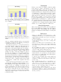
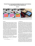
Tahuti: A Geometrical Sketch Recognition System for UML Class
Diagrams
Tracy Hammond and Randall Davis
AI Lab, MIT
200 Technology Square
Cambridge, MA 02139
hammond, [email protected]
Abstract
We have created and tested Tahuti, a dual-view sketch
recognition environment for class diagrams in UML.
The system is based on a multi-layer recognition framework which recognizes multi-stroke objects by their geometrical properties allowing users the freedom to draw
naturally as they would on paper rather than requiring
the user to draw the objects in a pre-defined manner.
Users can draw and edit while viewing either their original strokes or the interpreted version of their strokes
engendering user-autonomy in sketching. The experiments showed that users preferred Tahuti to a paint
program and to Rational RoseT M because it combined
the ease of drawing found in a paint program with the
ease of editing available in a UML editor.
Introduction
Sketching is a natural and integral part of software design. Software developers use sketching to aid in the
brainstorming of ideas, visualizing programming organization and understanding of requirements. Unfortunately when it comes to coding the system, the drawings are left behind. Natural sketch recognition bridges
that gap by allowing users to sketch as they would on
paper, and since the sketch is recognized, allowing the
sketch itself to take an active role in the coding process.
Paper sketches offer users the freedom to sketch as
they would naturally; for instance, users can draw objects with any number of strokes and strokes may be
drawn in any order. However, because paper sketches
are static and uninterpreted, they lack computer editing features, requiring users to completely erase and
redraw an object to move it.
Unified Modeling Language (UML) diagrams (Booch,
Rumbaugh, & Jacobson 1998) are a de facto standard for depicting software applications. Within UML,
class diagrams play a central role in describing program
structure. Many of the symbols used in class diagrams
are quite similar, and hence they offer an interesting
challenge for sketch recognition.
Traditional CASE (Computer Automated Software
Engineering) tools, such as Rational RoseT M , give users
powerful editing features, and even allow users to automatically generate skeleton user code. However, these
CASE tools give the users very little if any flexibility
to create a diagram. Users do not have the freedom to
sketch their designs and are required to learn a large
number of commands before they can use the system
with ease.
We have created Tahuti1 , a multi-stroke sketch recognition environment for class diagrams in UML where
users can sketch the diagrams on a tablet or whiteboard in the same way they would on paper and the
sketches are interpreted by the computer. Our system
differs from graffiti-based approaches to this task in that
it allows users to drawn an object as they would with
pen and paper. The system recognizes objects based on
their geometrical properties by examining the line segments’ angles, slopes, and other properties, rather than
requiring the user to draw the objects in a pre-defined
manner. Recognizing the objects by their geometrical
properties gives users the freedom to sketch and edit
diagrams as they would naturally, while maintaining a
high level of recognition accuracy.
In order to recognize the objects created from multiple strokes by their geometrical properties, we have
created a multi-layer framework of recognition in which
strokes are preprocessed, selected, recognized, and then
identified.
Upon recognition of an object the sketch recognition
process most sketch recognition software replaces the
users strokes with cleaned-up strokes that they did not
draw. Some users are distracted by this process, preferring that their original strokes remain. Tahuti permits
users to draw and edit, while viewing either their original strokes or the cleaned-up version of their strokes,
thus engendering user-autonomy in sketching. The system is also non-modal: users can edit or draw without
having to give any explicit command or mode change.
To test the usability of Tahuti, we performed a field
experiment in which subjects compared Tahuti to a
paint program and to Rational Rose. Subjects created
and edited a UML class diagram, using each method
and quantifying the ease of drawing and editing of each
method.
1
Tahuti, also known as Thoth, is the Egyptian god of
wisdom. He always carried a pen and scrolls upon which he
recorded all things.
This paper is organized as follows. First, we review
previous work on UML diagram sketch recognition.
We then describe the multi-layer recognition framework
used by the system and follow it with a discussion of
the recognition algorithms used in the code and the
multi-view interface. Next, we discuss the advantages
of the Rational RoseT M interface. Finally, we present
the results of our field experiment and offer directions
for future research.
Previous Work
A Wizard of Oz experiment showed that users prefer
a single-stroke sketch-based user interface to a mouseand-palette based tool for UML design (Hse et al. 1999).
Users, though happy with the single-stroke version, requested more sketching flexibility, such as the ability to
draw with multiple strokes.
Ideogramic UMLT M (Damm, Hansen, & Thomsen
2000), a graffiti based diagramming tool, requires users
to draw each single-stroke gesture in the style specified
in the user manual. A consequence of the single stroke
limit is that some of the gestures drawn only loosely
resemble the output glyph. For example, ϕ is used to
indicate an actor, drawn by the system as a stick figure.
Edward Lank et al. built a UML recognition system
that uses a distance metric (Lank, Thorley, & Chen
2000) which classifies strokes based on the total stroke
length compared to the perimeter of its bounding box.
This algorithm can cause many false positives. (For example, the letter M can be detected as a box.) Although
the system does allow users to draw somewhat naturally, it does not allow users to edit naturally. Users
don’t sketch edits to their diagrams, but rather use correction dialogue boxes.
The domain of UML class diagrams is a node and
link domain. Another system based on a node and link
domain is Denim (Lin et al. 2001), which recognizes
boxes and two link types to allow users to sketch and
design web pages. However, in Denim, the link types
are differentiated not by the geometrical properties of
the drawn links, but rather by what the links connect.
UML class diagrams are a subset of the software design domain. Other work has been done in the area
of software design sketch recognition. Eric Lecolinet
(Lecolinet 1998) has created a system to design GUIs
based on modal interaction where the user is required to
select an appropriate drawing tool. His system is quite
different from the system that we are designing in that
it does not allow free hand drawing and thus does not
perform sketch recognition, but it does display an interesting use of sketch gestures.
Landay (Landay & Myers 1995) has created SILK
a tool that allows users to sketch interactive user interfaces. SILK was one of the first systems that recognized a sketch and allowed interactive use of the sketch
without replacing the strokes with cleaned-up strokes
and allowing the user to view and modify her originally
drawn strokes.
SILK and many other systems were based on the
Rubine (Rubine 1991) recognition engine. The Rubine
recognition engine recognizes objects statistically with
the use of a linear discriminator, which processes a single stroke and determines certain features of it. The
Rubine system does not break down the stroke into line
segments or curves which prevents the creation of a hierarchical multi-stroke system of recognition.
Bimber, Encarnacao, and Stork created a multilayer architecture for sketch recognition (Bimber, Encarnacao, & Stork 2000) of three-dimensional sketches.
Their system recognizes objects created by multiple
strokes with the use of a simple BNF-grammar to define the sketch language. However, due to the nature of
their domain, the system requires users to learn drawing
commands before using the system rather than giving
users the freedom to draw as they would naturally.
Multi-Layer Framework for Sketch
Recognition
Our system uses a multi-layer framework for sketch
recognition. The multi-layer framework allows the system to recognize multi-stroke objects by their geometrical properties. The stages of the multi-layer recognition
framework are: 1) Preprocessing 2) Selection 3) Recognition 4) Identification.
After each stroke is drawn, rudimentary processing is
performed on the stroke, reducing the stroke to an ellipse or a series of line and curve segments. A collection
of spatially and temporally close strokes is chosen, and
the line segments contained in the collection of strokes
are then recognized as either an editing command or a
viewable object.
Figure 1 shows the stages of the multi-layer recognition framework applied to a drawn UML aggregation
association.
Stage 1: Preprocessing
At the most basic level, strokes drawn by the user are
processed using algorithms for stroke processing developed in our group (Sezgin, Stahovich, & Davis 2001).
The preprocessing stage uses stroke timing data to find
possible corners as users tend to slow down while drawing a corner. A stroke is processed only once, immediately after having been drawn. The stroke is fit to each
of the following 1) an ellipse, 2) a line, 3) a polyline,
which is a collection of line segments, and 4) a complex
shape, which is a collection of line segments and bezier
curves. Along with the original data points, the stroke
data structure contains each possible interpretation and
its probability of correctness.
Figure 1a shows us the originally drawn strokes of
a UML aggregation association. The diamond-headed
arrow was drawn using two strokes. The stroke is processed immediately after it is drawn. The data structure
of the strokes will contain a fit for a best fit ellipse, line,
polyline, and complex shape. In Figure 1b we see the
polyline interpretation of the strokes.
last nine unrecognized strokes can possibly be included
in a stroke collection.
All recognizable objects within the UML class diagram domain are connected objects. Thus we require
all strokes within a collection to be within close proximity of other strokes in the collection. Let C be the
collection of all of the strokes. Let S be a subset of the
strokes. For every subset S, where S is nonempty and
C − S is nonempty, we require that the smallest distance between the subsets be less than a threshold τ .
(SubsetDistance(S, C −S) < τ ) Experimentally, we set
τ to be 10 pixels.
[
[ j=1..m
D(Xi , Yj ))
SubsetDistance(X, Y ) = M in(
i=1..n
Figure 1: Multi-layer framework of recognition used in
Tahuti: A UML aggregation association is identified using the multi-layer recognition framework. a) The association was originally drawn using two strokes. b)
During the preprocessing stage, the original strokes are
processed into line segments. c) The two strokes of the
arrow are then selected for recognition. d) Recognition
occurs on the two strokes, at which point a UML aggregation association is deemed as a possible interpretation. e) The collection of strokes is identified as a UML
aggregation association.
(1)
In the above equation, n and m are the number of line
segments in X and Y respectively and Xi represents the
ith line segment. D is the distance function computing
the distance between two points.
In Figure 1c we see the two strokes of the UML aggregation association selected. Note that this is not the
only collection that would have been created. Assuming
that the arrow shaft was drawn first, after the arrow
shaft was drawn, a stroke collection would have been
formed with only that stroke. Another stroke collection
would have been formed with only the stroke of the arrow head. If other unrecognized strokes are present in
the diagram, several more stroke collections including
these strokes would be created for recognition testing.
After all stroke collections have been created, the recognition stage attempts to recognize the stroke collections
as possible viewable objects or editing commands.
Stage 2: Selection
Stage 3: Recognition
After the recently drawn stroke has been preprocessed,
the stroke is combined with zero or more unrecognized
strokes to form a collection of strokes. This collection
of strokes is then sent to the recognizer where it checks
if the combined strokes form a recognizable object or
editing command.
Ideally, all possible stroke combinations would be
tested for possible recognition of a recognizable object
or editing command. However, if we allow the system
to test for all possible stroke combinations, it would
take exponential time based on the number of strokes
to identify an object. While this is okay for small diagrams, this would be unacceptable for large diagrams,
making the system unusable. To reduce the number of
stroke collections for recognition, we use spatial and
temporal rules to prune off stroke collections.
To ensure that all interactions take polynomial time
based on the number of strokes, we limit the number of
strokes in a collection to a threshold. Experimentally,
we have found that 9 strokes is an acceptable threshold. Since users tend to draw an entire object at one
time, finishing to draw one object before drawing the
next, it is generally safe to form stroke collections consisting only of strokes drawn recently. Thus, only the
During the recognition stage, all stroke collections are
examined to see if a particular stroke collection could
be interpreted as a viewable object or an editing command. An editing command is a collection of strokes
indicating deletion or movement of a viewable object.
The system currently recognizes eight viewable objects:
a general class, an interface class, an inheritance association, an aggregation association, a dependency association, an interface association, text, or a collection of
unrecognized strokes. The algorithms used in the recognition stage will be described in more detail in the next
section.
If more than one interpretation is possible for any
stroke collection, the final interpretation is deferred until the identification stage. In Figure 1e we see that the
arrow recognition algorithm accepted the two selected
strokes as a UML aggregation association. Other stroke
collections presented to the recognition stage also have
interpretations. For example, the collection of strokes
consisting only of the arrow head stroke is recognizable
as a general class since it forms a square-like shape. The
decision between choosing the general class interpretation and the UML aggregation association is deferred
until the identification stage.
Stage 4: Identification
During the identification stage, a final interpretation
is chosen, and a collection of strokes is identified as
a viewable object or an editing command. All possible interpretations found in the recognition stage from
the stroke collections are presented to the identification
stage. The identification stage selects the final interpretation based on the following rules.
Object Movement An interpretation of object movement has priority over any other possible interpretation. Object movement recognition is interesting
in that it is the only interpretation that can be decided on while the stroke is still being drawn. If object movement is recognized, the multi-layer recognition framework will be short-circuited, preventing the
stroke to be recognized by other algorithms. Immediate recognition is necessary for movement to allow
the user to visually move the objects in real time,
rather than having the object move only after the
stroke is completed.
Any Interpretation Any interpretation is preferred
to no interpretation, where no interpretation leaves
the stroke collection as a collection of unrecognized
strokes.
Many Strokes We prefer to recognize collections with
a larger number of strokes since our goal is to recognize as much of what the user draws as possible.
Correctness Probability Each algorithm has a
ranking based on its probability of correctness. The
probability of correctness is a combination of both
prior and predicted probability. Certain recognizers
have a higher level of accuracy than others, giving
a prior correctness probability. Predicted probability
is calculated during recognition, for example, the ellipse fit predicted probability of correctness is much
higher for a perfectly drawn ellipse than a crooked
ellipse. If more than one interpretation is still possible, the interpretation with the highest ranking is
then chosen.
After the final interpretation is chosen, the associations are examined to see if any unconnected associations can be connected to a class. This is done by checking if an association endpoint lies on or near a general
or interface class.
Recognition Stage Algorithms
Figure 2: Rectangle Recognition Process. a)The line
segments of the polyline fit of the strokes. b) The endpoints of the line segments from a) are specified. c) The
endpoints of one line segment have been labelled. d)
The endpoints of two line segments have been labelled.
e) All line segments have been labelled. f) The new line
segments after the joining.
parallel to the horizontal plane or that it be created
from a single stroke or even one stroke per side. The
algorithms inputs are the lines segments of the polyline
fit of the preprocessed strokes. (See Figure 2a-b.) The
six steps are:
1. Confirm that the preprocessed collection of strokes
consist of at least 4 line segments of non-trivial size
(> 10 pixels).
2. Order the lines into a circular path by numbering the
endpoints one by one:
(a) Select a line segment to start. Label it’s first endpoint 0. Label its other endpoint 1. (See Figure 2c.)
(b) Find the closest unlabelled endpoint to the last labelled endpoint n. Label it n + 1 and the other
endpoint of the segment n + 2. (See Figure 2d-e.)
(c) Repeat above until all endpoints are labelled.
3. Confirm that first endpoint labelled is relatively close
to the last endpoint labelled (i.e., that the distance is
< 1/4 of the distance between the two points furthest
apart.)
During the recognition stage of the multi-layer recognition framework, stroke collections are tested for possible interpretations. In particular, we present here the
recognition algorithms for rectangle, ellipse, arrow, and
editing action recognition.
4. Join lines that have adjacent endpoints with a similar
slope. (See Figure 2f)
Rectangle Recognition
The above algorithm recognizes rectangles containing
any number of strokes. The strokes can be drawn in any
order, and the strokes can stop or start anywhere on the
side of the rectangle. The algorithm emphasizes that the
rectangle be recognized by its geometrical properties
General classes are represented as rectangles in UML
class diagrams. To recognize rectangles we constructed
an algorithm based on a rectangle’s geometrical properties. The algorithm does not require that the class be
5. Confirm that there are four lines left.
6. Confirm that every other line is parallel and that adjacent lines are perpendicular.
rather than the method in which it was drawn. This
method allows users to draw as they would naturally
without sacrificing the recognition accuracy.
Ellipse Recognition
Interface classes are represented as ellipses in UML class
diagrams. After a stroke has been preprocessed, if the
ellipse fit has the highest probability compared to the
complex shape, polyline, or line fit, the interface class
recognition algorithm accepts the stroke as an interface.
The algorithm accepts only a single stroke in the collection of strokes because the ellipse recognizer created
by (Sezgin, Stahovich, & Davis 2001) is only a single
stroke recognizer since it depends on the time and speed
data of the stroke. To recognize multi-stroke ellipses, we
could assemble two curves together in a process similar to the rectangle recognizer, but in practice this has
not been necessary. The single stroke requirement for
the interface class is not a hindrance to the user since
circles are almost always drawn with a single stroke.
Arrow Recognition
We present here two methods for arrow recognition, geometrical and contextual. The geometrical method is
used if the user has drawn an arrow complete with an
arrow head to specify the association type. The contextual method is used if the user has only drawn the
arrow shaft connecting two classes, letting the application assume the dependency association.
Geometrical Method for Arrow Recognition
Associations are represented by arrows in UML of which
there exist three types: aggregation association with a
diamond arrow head, inheritance association with a triangular arrow head, and dependency association with
an open arrow head (See Figure 3. The recognition algorithm uses the polyline fit of the preprocessed strokes.
To facilitate recognition of all three types, we identified five feature points (A, B, C, D, E) as labelled in
Figure 1d and Figure 3.
1. Locate the arrow shaft by locating the two points
furthest from each other (points A and B).
2. Locate the arrow head ends by locating points furthest from arrow shaft on either side (points C and
D).
3. Let point E be the point on line AB that is twice the
distance from B as the intersection point of lines CD
and AB.
4. Classify each of the line segments as part of the arrow
shaft, an arrow head section, or unclassified (AB, BC,
BD, CD, CE, DE, or unclassified) based on the line’s
bounding box, slope, and y-intercept.
5. Compute the total length of each of the line segments
in each section (AB, BC, BD, CD, CE, DE, or unclassified). A section is said to be filled if the total
length of each of the line segments in each section is
greater than half the ideal length of the segment.
Figure 3: Points A, B, C, D, and E as determined in
the arrow recognition algorithm
6. Confirm sections AB, BC, and BD are filled.
7. Confirm that the unclassified section accounts for less
than 1/4 of the total strokes length.
8. Based on the results of the line-segment classification,
classify the arrow type as follows:
(a) open head: CD, CE, and DE not filled
(b) diamond head: CE and DE filled
(c) diamond head: CD not filled and either CE or DE
filled
(d) triangular head: Either CE or DE not filled and
CD filled
Contextual Method for Arrow Recognition
Contextual information can be used to recognize arrows. If a stroke without a specified arrow head starts in
one class and ends in another, the stroke is interpreted
as an arrow. The stroke is assumed to be a dependency
relationship with the first class being dependent on the
second if both classes are general classes. In this case
the dependency arrow head is added to the interpreted
diagram. If one class is an interface class, the interpreted diagram replaces the stroke with a straight line
connecting the two classes creating an interface association. The association is attached to the classes and
will move in accordance with the classes if the class is
moved.
Deletion Recognition
Deletion is indicated by scribbling over an object. We
define class deletion lines to be the horizontal, vertical
and diagonal lines passing through the body of a class.
Deletion of an interface or general class is recognized
by checking if the stroke collection crosses a deletion
line of the class more than four times. Deletion of a
relationship is recognized by checking if the collection
of strokes crosses the arrow more than four times. More
than one object can be deleted with a single deletion
command.
Movement Recognition
A stroke is recognized as a movement action if the user
has clicked and held the cursor over the body of a class
or the endpoint of an association with relatively little
movement for a period of time greater than a half second. After the stroke is identified as a movement action,
the cursor changes to a gripping hand and any further
Figure 4: Interpreted UML class diagram
Figure 6: Diagram of Figure 4 with the classes moved,
Figure 5: Drawn view of Figure 4
Figure 7: Drawn view of Figure 6
movement of the cursor will move the object appropriately. Recognition of a stroke as movement of an object must occur during the stroke, rather than after the
stroke is completed. In this case, the recognition process is short-circuited and no other interpretations are
attempted.
If an interface or general class is moved, any relationships attached to the class will remain attached moving
in rubber-band format. If a relationship is moved, the
endpoint moved will detach from any class it is currently attached to. Once the relationship is moved and
the mouse released, the relationship endpoint is examined to see if it should be reattached to a class or remain unattached. It is possible for a relationship type to
change from an aggregation, inheritance, or dependency
relationship to an interface relationship if the arrow is
moved from a general class to an interface class, or vice
versa.
we can see that the identified text describing the ObjectRendered class remains attached to the correct class
when the class is moved. In future work, we intend to
perform character recognition on the text.
Although we currently do not recognize text, class,
property, and method names can be named using a
form. Text can be input into the form using the panel
keyboard and a mouse or by typing directly with the
keyboard. Figure 8 shows a picture of the form inputting information for the Game class. Notice that the
information on the form is also updated on the diagram.
Text
Text can be handwritten directly onto the class. In Figures 4-7, the ObjectRendered class contains the text
desciption ”graphics”. Note the the text is not recognized, but merely identified as text. It is identified using
a combination of properties such as size and location.
The text must be small in comparison to the class size.
The text must lie inside of or near a class. In Figures 4-7
Multi-View System
While sketching, the user can seamlessly switch between
two views: the drawn view (Figure 7) which displays
the users original strokes or the interpreted view (Figure 4) which displays the identified objects. Users can
draw and edit in either view. Editing commands operate identically in the two views, with the drawn view
allowing users to view and edit their original strokes.
When a class is dragged, the strokes of an attached association must be stretched, translated, and rotated in
order for it to remain attached and the strokes faithful
to those originally drawn. Figure 6 shows the results after moving classes in Figure 4. The drawn view is shown
in Figure 7.
The strokes shown in the drawn view are not the same
Figure 9: Rational Rose diagram of Figure 4
Figure 8: Class names, property names, and method
names can be input into the form using the panel keyboard and a mouse or by typing directly with the keyboard.
as those shown in the interpreted view. Several complications arise from this. One such complication is that we
now have to keep track of three different sets of stroke
data for each stroke drawn. Thus for each viewable object, the data structure must contain 1) the original
strokes, 2) the uninterpreted strokes (the strokes viewable in the drawn view), and 3) the interpreted strokes
(the strokes viewable in the interpreted view). The uninterpreted strokes are not the same as originally drawn
strokes since the object may have been moved, causing
the viewable strokes to have been stretched, translated,
or rotated. After movement of an object, the uninterpreted strokes are recalculated based on the original
strokes rather than the current uninterpreted strokes
to ensure no loss of accuracy.
Since the originally drawn strokes and the viewable
strokes in the interpreted view are different, the recognition algorithms must take into account the current
view. For example, when deleting an association in the
interpreted view, the line or arrow shaft representing
the relationship must be crossed. However, in the drawn
view, the stretched, scaled, or rotated original strokes
representing the relationship must be crossed.
Rational RoseT M Diagrams and Code
Generation
Since Tahuti has recognized the UML diagram, it can
generate Rational RoseT M diagrams, providing additional benefits to the user. Rational Rose is popular in
industry as it offers a wide number of powerful features
such as the ability to create a UML diagram from code
and automatic code generation. Figure 9 displays the
Rational RoseT M diagram generated from the diagram
in Figure 4.
Rational Rose can generate base Java code for each
of the interface and general classes in the UML class
Figure 10: Code automatically generated by Rational
RoseT M for Deck and Hand class.
diagram. Class names entered using the form in Figure 8 will appear in the automatically generated Rational RoseT M diagram and the automatically generated
Java code. Figure 10 displays the automatically generated code of two classes. Notice that the Hand class
extends the Deck class and that the Deck class implements the Dealable interface, as specified in the original
sketch.
Experiment
In a preliminary study, six subjects were asked to draw
and edit a UML diagram in four different ways: A) using
a paint program, B) using Rational RoseT M C) using
Tahuti in interpreted view D) using Tahuti in drawn
view. Subjects were aided in the use of Rational Rose if
they were unfamiliar with it, but little instruction was
given otherwise.
The subjects were asked to rank the four methods
on a continuous scale from zero to five (with zero being the hardest and five being the easiest) both for ease
of drawing and for ease of editing. Figure 11 displays
the results for ease of drawing. Figure 12 displays the
results for ease of editing. The results display that subjects greatly preferred the interpreted sketch interface
of Tahuti.
At the end of the study, a brief interview was held
with each subject. During this time, the subjects stated
that they appreciated having the freedom to draw as
they would on paper along with the editing intelligence
of a computer application. Subjects said that editing
was difficult in the paint program because of the large
amount of re-sketching required for class movement.
Conclusion
Figure 11: Results of user study for ease of drawing.
Note that users preferred drawing in the interpreted
view of Tahuti.
We have created and tested Tahuti, a dual-view, multistroke sketch recognition environment for class diagrams in UML. Tahuti combines the sketching freedom
provided by paper sketches and the processing power
available in an interpreted diagram. The system is based
on a multi-layer recognition framework and recognizes
objects by their geometrical properties, rather than requiring that the user draw the objects in a pre-defined
manner. By recognizing objects by their geometrical
properties, Tahuti allows users to sketch as they would
naturally without sacrificing the recognition accuracy.
The experiments showed that users preferred Tahuti
to a paint program and to Rational RoseT M because it
combined the ease of drawing found in a paint program
with the ease of editing available in a UML editor.
Acknowledgements
This work is supported in part by the Ford/MIT Alliance and the MIT Oxygen Collaboration. The authors
appreciate the help of Louis-Philippe Morency, Michael
Oltmans, and Raghavan Parthasarthy in reviewing this
paper.
References
Figure 12: Results of user study for ease of editing. Note
that users preferred editing in the interpreted view of
Tahuti.
Subjects complained that Rational Rose was extremely
nonintuitive and that they had difficulty performing the
commands they wished to perform.
Most subjects preferred to work in the interpreted
view rather than the drawn view. The subjects contrasted the domain of UML class diagrams with domains such as Mechanical Engineering and Architecture where a cleaned-up drawing may imply a finished
design. They stated that the domain of UML class diagrams is one where cleaned-up drawings are appreciated since the drawings are created in the design stage
and cleaned-up drawings do not imply solidified ideas.
The subjects said that they would prefer to work in the
drawn view in a domain such as Mechanical Engineering and Architecture. The subjects predicted that the
drawn view would be a valuable feature in any domain
to allow them to examine their original strokes when
necessary.
Our experiment suggests that future system enhancements should consider incorporating an ability to recognize multiplicity relationships and modification of recognized objects, (e.g., changing a dependency association into an inheritance association by adding a stroke).
Further field evidence is, however, necessary before any
categorical recommendations can be made in this area.
Toward this end, future research should test Tahuti,
using larger samples, tighter controls, and varied experimental setting.
Bimber, O.; Encarnacao, L. M.; and Stork, A. 2000.
A multi-layered architecture for sketch-based interaction
within virtual environments. In Computers and Graphics,
volume 24, 851–867.
Booch, G.; Rumbaugh, J.; and Jacobson, I. 1998. The
Unified Modeling Language User Guide. Reading, MA:
Addison-Wesley.
Damm, C. H.; Hansen, K. M.; and Thomsen, M. 2000.
Tool support for cooperative object-oriented design: Gesture based modeling on an electronic whiteboard. In CHI
2000. CHI.
Hse, H.; Shilman, M.; Newton, A. R.; and Landay, J.
1999. Sketch-based user interfaces for collaborative objectoriented modeling. Berkley CS260 Class Project.
Landay, J. A., and Myers, B. A. 1995. Interactive sketching
for the early stages of user interface design. In CHI, 43–50.
Lank, E.; Thorley, J. S.; and Chen, S. J.-S. 2000. An interactive system for recognizing hand drawn UML diagrams.
In Proceedings for CASCON 2000.
Lecolinet, E. 1998. Designing guis by sketch drawing and
visual programming. In Proceedings of the International
Conference on Advanced Visual Interfaces (AVI 1998).,
274–276. AVI.
Lin, J.; Newman, M. W.; Hong, J. I.; and Landay, J. A.
2001. Denim: An informal tool for early stage web site
design. In Video poster in Extended Abstracts of Human
Factors in Computing Systems: CHI 2001, pp. 205–206.
Rubine, D. 1991. Specifying gestures by example. In
Computer Graphics, volume 25(4), 329–337.
Sezgin, T. M.; Stahovich, T.; and Davis, R. 2001. Sketch
based interfaces: Early processing for sketch understanding. In The Proceedings of 2001 Perceptive User Interfaces
Workshop (PUI’01).