1
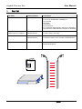
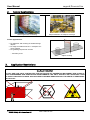
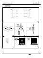
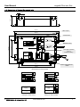
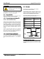
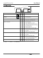
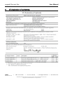
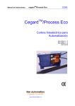
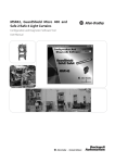
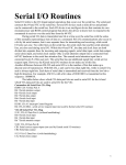
User Manual Light array cegard / Process Eco English Deutsch IMPORTANT NOTE FOLLOW THE INSTRUCTIONS GIVEN IN THIS MANUAL CAREFULLY. FAILURE TO DO SO MAY CAUSE CUSTOMER COMPLAINTS AND SERIOUS CALL BACKS. KEEP INSTRUCTION MANUAL ON SITE. © CEDES Safety & Automation AG Version 1.4 / Jan. 2014 Part No. 102 153 E cegard/Process Eco 1. User Manual Part list Part Name Catalog Number Description Process Eco System 45CSA-103608-Mxxxx According configuration sheet Mxxxx with 8, 16, 24 or 32 elements, consisting of : A) Controller B) Emitter C) Receiver D) This manual E) Connection cable (Emitter, with plug or attached) R) Connection cable (Receiver with plug or attached) Control unit EcoC-230-Rel Control unit EcoC-24-Rel-T 45CSA-102075 45CSA-104458 17 … 240 VAC / DC, Relay 24 VDC, Relay, Test input Connection Cable 445L-106507 45CSA-104481 Connection Cable, 8 Pin, 5 Meter, MiniDin/M-RJ45 Connection Cable, 8 Pin, 15 Meter, MiniDin/M-RJ45 Extension Cable 445L-102793 Extension Cable, 8 Pin, 3 Meter, MiniDin/M-MiniDin/F E R CEDES cegard/Process Eco manufactured under ISO 9001: 2000 D CEDES Part No. 102 075 resp. 104 458 or 103 189 A B 2 www.cedes-sa.com C © CEDES Safety & Automation AG cegard/Process Eco User Manual 2. Typical Applications Overhang/Excess monitoring Object detection on transport conveyor Further applications: • For detection and counting of small and large objects • For large surveillance zones i.e. transport conveyor systems • For guarding objects from access ... and many more Object counting 3. Application Restrictions CAUTION! DO NOT USE THIS LIGHT CURTAIN FOR THE PROTECTION OF DANGEROUS MACHINERY NOR IN EXPLOSIVE ATMOSPHERES NOR RADIOACTIVE ENVIRONMENTS! USE ONLY SPECIFIC AND APPROVED TYPES OF SAFETY DEVICES FOR SUCH APPLICATIONS OTHERWISE SERIOUS INJURY OR DEATH OF PERSONNEL MAY OCCUR! © CEDES Safety & Automation AG www.cedes-sa.com 3 cegard/Process Eco 4. User Manual Installation no oil! 20° 20° min. 80 mm ± 10° E E 4 R R Other light sources www.cedes-sa.com E > 100'000 lux R E R Other light sources © CEDES Safety & Automation AG cegard/Process Eco User Manual CSA-102075 CSA-104458 17...240 VAC/DC 24 VDC N P Common nc no - 0V 24V Common nc no 0 VDC 24 VDC WAGO Connector 6x 5.08 6.3AT Test Input 45CSA-104458 only WAGO Connector 2x 5.08 Switch Controller Process Eco Jumper 0...10 s (Timer) Output: Relay NC NO Common © CEDES Safety & Automation AG NC NO Common www.cedes-sa.com 5 cegard/Process Eco User Manual 4.1. Process/Eco opto edges Figure 1: Process/Eco light curtain: Slim and robust aluminum profile: 12 x 16 mm f e Area of dense resolution Receiver Emitter Criss-cross Beams Straight Beams Figure 2: Criss-cross beams 6 www.cedes-sa.com © CEDES Safety & Automation AG cegard/Process Eco User Manual 4.2. Dimensions of Process/Eco control unit 45 (1.0") 5 (0.2") 200 (7.9") JP1: Jumper 188 (7.4") Potentiometer Receiver R LED E Out Switch S: Buzzer Power 80 (3.15") 128 (5.05") Emitter Test input connector (only on #45CSA-104458 ) Relais max. 250VAC / 8A 125VDC / 0.5A 30VDC / 8A 17-240VAC/DC max. 5 VA 130 (5.1") Power and output connector 160 (6.3") Dimensions in mm (inches) Jumper Jumper Rx Criss-Cross beams on Criss-Cross beams off LED Out Power Rx Tx Out LED Power Out Tx Power NO NC Output 8A / 250 VAC, 0.5A /125 VAC, 8A / 24 VDC 6.3AT Criss-Cross beams off Test Power Rx Criss-Cross beams on Output COM P N 17.. 240VAC/DC Rx Tx 24 VDC Out Power Tx + NO 8A / 250 VAC, 0.5A /125 VAC, 8A / 24 VDC NC COM Power 24V 0 24 VDC P-EcoC-230-Rel P-EcoC-24-Rel-T Catalog No. 45CSA-102075 Catalog No. 45CSA-104458 © CEDES Safety & Automation AG www.cedes-sa.com 7 cegard/Process Eco User Manual 4.3. Features 4.6. Installation • • • • • • • Due to the large optical aperture angle and the automatic calibration feature there is no alignment needed as long as the light curtains are within the specified aperture angle, picture ). Self-calibrating, fault tolerant Easy installation without alignment Dense surveillance area Robust and reliable Integrated diagnostics Very low price due to economy of scale Off time delay, adjustable 4.4. Applications cegard/Process Eco is ideal for more comfort on machines and automation processes. IMPORTANT WARNING: This product is not a safety sensor to protect human life or human injury from dangerous parts of machinery. For installation of the light curtains please note that, • both cables exit the profile in the same direction • they are securely fastened • they must not be bent or be exposed to tension • the cable is not stretched or squeezed • the cable is well fastened and routed • ensure a cable radius > 80 mm • avoid dirt on the light curtains • avoid contamination by oil or greasy fluids • avoid interference with other infrared sources like single opto sensors, energy saving lamps, direct sun light, etc. • Make sure that operating range corresponds with specifications of the emitter light curtain. Installation of control unit: The connection diagram inside the control unit explains correct connection and use: 4.5. Functional description Between emitter E and receiver R a high density surveillance area is built up with straight and crossed beams. A built-in calibration feature of each individual beam to eliminate any adjustment, suppress light interference or control influence from dirt. Automatically adjust the power to provide the optimal operating conditions. These features give cegard/Process Eco an outstanding functional reliability. Any interruption of the surveillance area by an object or a person will be detected and the output signal will be switched. • Fix the control unit with 4 screws. with low imped• Connect the earth terminal ance (< 10 Ω) to protective earth of the power supply. • Connect the blue connector (receiver curtain) to the receiver terminal and the white connector (emitter curtain) to the emitter terminal. Make sure the connectors are properly secured. • For controller with test input (45CSA-104458): Connect 0 V and + 24 VDC to the test input connector. • Connect the desired output signals. • Connect power. • Set Jumper JP1, Potentiometer and Switch S (see chapter "Operation" on page 9). • Close controller cover and screw tightly . • Switch power on. Light curtains calibration takes place within approximately 5 seconds. The buzzer is beeping during calibration. • Test controller output signal by interrupting light curtain . cegard/Process Eco is now ready! 8 www.cedes-sa.com © CEDES Safety & Automation AG cegard/Process Eco User Manual 4.7. Operation 4.7.4. Test input Danger 120 / 240 Volts Disconnect power before opening the control unit! The diagram of the control unit on page 5 (picture ) explains the connection and operation. 4.7.1. Buzzer (Switch S) Switch S activates the buzzer. The buzzer will be heard when the light curtain is interrupted. 4.7.2. Criss-cross beam mode (Jumper JP1) JP1 set = Criss-cross beam mode on JP1 off = Criss-cross beam mode off With the criss-cross beam mode is active, the smallest object size detected is in the area of high resolution (figure 2, page 6). In this area the minimum object size detected (f) is equivalent to half the element separation distance, plus 7 mm (beam diameter). In order for the criss-cross mode to function properly a minimum operating distance must be obeyed. This function is only available on the controller EcoC-24-Rel-T (45CSA-104458). The test input is used for turning the emitter off, and thereby provoking the controller output to also switch off. This functionality allows higher level controller to test the complete light curtain system. For normal operation of the light curtain system, +24 VDC must be connected to the test input. Condition 1 Test Input + 24 VDC Light beam interrupted Common - NC 2 Test Input + 24 VDC Light beam not interrupted Common - NO 3 Test Input 0 VDC Light beam not interrupted Common - NC 4 Test Input 0 VDC Light beam interrupted Common - NC 24 V With the criss-cross beam mode off, the response time is reduced. Minimum object size detected in this mode is equal to the element separation distance (e), plus 7 mm (beam diameter). Test Input 4.7.3. Output off delay (potentiometer) Relay Output The output can be delayed after the protective area is no longer interrupted. The delay time is adjustable with the potentiometer between 0 ... 10 s . Default is 0 s. Relay Output 0V min. 300 ms max. 200 ms max. 200 ms Figure 3: Timing of the test input 4.8. Cleaning the light curtain Use soapy water only. Any use of abrasive or inappropriate cleaning solvents may cause loss of range or failure. © CEDES Safety & Automation AG www.cedes-sa.com 9 cegard/Process Eco User Manual 4.9. Trouble shooting RECEIVER (R) JP1 OUT POWER EMITTER (E) 0 ... 10s green yellow Indication Person or object detected Action • Normal operation No object • Normal operation No function • Check power supply • Change fuse, order spare fuse Surveillance area not interrupted, output in off position • Test input = + 24 VDC (Pin 0V and 24V) connected? • Check installation and cables • Clean emitting and receiving surfaces • Interfering of foreign light sources (e.g. sun or IR-sensors). • Change control unit • Change emitter and receiver edge. • Check wiring and connectors • Connect E / R light curtain with protective earth? • Replace receiver light curtain Receiver R defective Emitter E defective R & E defective • Check wiring and connectors • Connect control unit and E / R light curtain with protective earth? Object not detected • Check for specular reflection from nearby parts and surfaces = LED on 10 = LED off • Check wiring and connectors • Connect E / R light curtain with protective earth? • Replace emitter light curtain = LED flashing www.cedes-sa.com © CEDES Safety & Automation AG cegard/Process Eco User Manual 5. Technical Data Control unit Type Catalog No Power supply Current consumption (without load) Relay output EcoC-230-Rel 45CSA-102075 EcoC-24-Rel-T 45CSA-104458 17 … 240 VAC / DC 24 VDC ± 20 % max. 280 mA max. 90 mA 250 VAC / 8 A 125 VDC / 0.5 A 30 VDC / 8 A min. 5 VDC / 10 mA 250 VAC / 8 A 125 VDC / 0.5 A 30 VDC / 8 A min. 5 VDC / 10 mA Test input no yes Connector 6 pin terminal block 6 & 2 pin terminal block Off time delay Indicators (LED) 0 .. 10 seconds Power, beam status, failure Enclosure rating (control unit) IP54 Temperature range - Operation - Storage -20 … +65°C -20 … +70°C Operation humidity 5 … 95 % non condensing Operation vibration / shock EMC Material housing IEC 60068-2-6 2006/95/EC (Low Voltage Directive), 2004/108/EC (EMC Directive) ABS, color blue (similar to RAL 5005) Weight Electrical lifespan Mechanical lifespan 350 g >100 * 103 operating cycles >20 106 operating cycles Light curtain Operation wave length Infrared approx. 900 nm No. of sensors per light curtain 8 / 16 / 24 / 32 No. of beams per sensor Operating range 1-3 0 … 5 m or 3 … 8 m according configuration Mxxxx (for criss-cross beams see minimum working distance restriction) Max. ambient light Minimum object size Minimum operating range in criss-cross operation mode 100'000 Lux Element separation + 7 mm 10x element spacing (dim e in Figure 2) Typical response time (without relay delay) - with criss-cross beams (Jumper on) - without criss-cross beams (Jumper off) (8, 16, 24, 32 elements) 32 ms, 58 ms, 82 ms, 110 ms 23 ms, 40 ms, 57 ms, 78 ms Max Response time (without relay delay) - with criss-cross beams (Jumper on) - without criss-cross beams (Jumper off) (8, 16, 24, 32 elements) 64 ms, 116 ms, 164 ms, 220 ms 46 ms, 80 ms, 114 ms, 156 ms Light curtain length Position mounting holes [mm] Cable length According to configuration Mxxx (max 2.4 m) According to configuration Mxxx Standard: Pigtail with Mini-Din, 5 m connector cable each Customer specification: Fixed cable (no connector) emitter up to 10 m / receiver up to 30 m Temperature range - Operation - Storage -20 ... +65°C -20 ... +70°C Operation humidity 5 … 95 % non condensing Vibration / shock EMC IEC 60068-2-6 2006/95/EC (Low Voltage Directive), 2004/108/EC (EMC Directive) Enclosure rating IP65 (IP67 upon request) Materials: Lenses / Profiles Polycarbonate / Aluminum Color of profiles Aluminum anodized (standard) or black anodized Weight / profile 150 g (light curtain length 500 mm) © CEDES Safety & Automation AG www.cedes-sa.com 11 cegard/Process Eco 6. User Manual CE declaration of conformity CEDES +41 81 307 8200 Fax +41 81 307 8201 [email protected] Safety & Automation AG CEDES Safety & Automation AG reserves the right to modify or change technical data without prior notice. Copyright © 2011 Rockwell Automation, Inc. All rights reserved www.cedes-sa.com