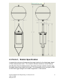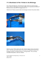
1
Precision Measurement Engineering, Inc. • www.pme.com
LakeLogger User’s Manual
2010
Precision Measurement Engineering, Inc.www.pme.com
(760) 727-0300
www.pme.com
1
(INTENTIONALLY BLANK)
Precision Measurement Engineering, Inc.www.pme.com
(760) 727-0300
www.pme.com
2
Warranty
1-YEAR LIMITED WARRANTY ON LakeLogger HARDWARE
Precision Measurement Engineering, Inc. (PME) warrant that the LakeLogger shall
be free of defects in workmanship and materials, under normal use, for a period of
one year from the date of shipment. This warranty is made only to the original
purchaser. In the event a LakeLogger covered by this warranty fails to operate
according to our published specifications, return it freight pre-paid to PME or an
authorized Service Provider. PME will repair the unit at no charge to the customer,
and bear the cost of return shipment. Carefully pack all components, as the customer
is responsible for any freight damage.
This warranty does not apply to services or consumable/ expendable items (such as
batteries, fuses and ropes) required for general maintenance. Equipment
manufactured by other companies (such as meteorology sensors, solar panels, etc)
are warranted only to the limit of the warranties provided by their original
manufacturer.
PME makes no warranty, either expressed or implied, that the sensors will be
operable after they are exposed to adverse environmental conditions, such as biofouling, oil fouling, freezing temperatures or others.
This warranty is void if, in our opinion, the LakeLogger has been damaged by
accident, mishandled, altered, or repaired by the customer, where such treatment has
affected its performance or reliability. In the event of such treatment by the customer,
costs for repairs plus two-way freight costs (no COD shipments will be accepted) will
be borne by the customer. In such cases, an estimate will be submitted for approval
before repair work is started. Items found to be defective should be returned to PME
carefully packed, as the customer will be responsible for freight damage.
Incidental or consequential damages or costs incurred as a result of the product
malfunction are not the responsibility of PME.
For all warranty or non-warranty returns please obtain, complete, and submit a RMA
to PME. This RMA form may be obtained at
http://www.pme.com/HTML%20Docs/RMAform.html.
After submission of this from PME will respond with a RMA number. Please place
this number on all shipments and related communications.
Precision Measurement Engineering, Inc.www.pme.com
(760) 727-0300
www.pme.com
3
Safety Information
BURSTING HAZARD
Should water enter the logger and come into contact with the enclosed batteries the
batteries may generate gas causing the internal pressure to increase. This gas will
likely exit via the same location that the water entered, but not necessarily. If internal
pressure is suspected the blue housing should be carefully unscrewed no more than
1 full turn. This will relieve the internal pressure by breach of the housing o-ring.
Precision Measurement Engineering, Inc.www.pme.com
(760) 727-0300
www.pme.com
4
Revision History
Date
20-JUL-2010
01-DEC-2010
07-DEC-2010
13-AUG-2012
18-AUG-2012
20-AUG-2012
Revision Description
Initial document
Extensively revised for new blue housing
Added graphs
Extensive modification to remove Data Turbine and reformat
Made some spelling corrections.
Added drawing of upper part of system
Precision Measurement Engineering, Inc.www.pme.com
(760) 727-0300
www.pme.com
5
CONTENTS
Chapter 1:
1.1
Introduction to the LakeLogger
Chapter 2:
2.1
2.2
2.3
2.4
2.5
Software
Overview
ESP_DataPipeLine
ESP_Plot
Hyperterminal
TextPad
MySQL Vega Database
Matlab
Chapter 5:
5.1
5.2
5.3
5.4
5.5
5.6
5.7
5.8
5.9
5.10
Measurement Flow
Overview
Logger Scanning
File Copy
Shore Logger Files and Folders
Engineering Unit Files
Matlab
MySQL/Vega
ESP_Plot
Chapter 4:
4.1
4.2
4.3
4.4
4.5
4.6
4.7
Specifying LakeLogger
Overview
LakeLogger Location
Form 1, Station Specification
Form 2, T-Chain Sensor Positions
Bathymetry Map
Chapter 3:
3.1
3.2
3.3
3.4
3.5
3.6
3.7
3.8
Introduction
LakeLogger Logger
Overview
Opening and Closing the Logger
Connections and Controls
Output after Power On
Mission Operation
RS232 I/O Connection
File Save Button
Battery Life
Battery Replacement
Commands
Precision Measurement Engineering, Inc.www.pme.com
(760) 727-0300
www.pme.com
6
Chapter 6:
6.1
6.2
6.3
Overview
Calculation of T-Chain Sensor Height
Calibration File Keywords
Chapter 7:
7.1
7.2
7.3
7.4
7.5
7.6
7.7
7.8
LakeLogger Deployment
Overview
Items Required
Beginning a Deployment
Deploy the LakeLogger
Recover the LakeLogger
Ending a Deployment
Chapter 9:
9.1
9.2
LakeLogger Assembly
Overview
Tools Required
Unpacking and Inspection
Connection of the T-Chain
Attachment of the T-Chain to the Birdcage
Connection of the T-Chain to Anchor Rope
Connection of the Float
Anchor and Retrieval Rope
Chapter 8:
8.1
8.2
8.3
8.4
8.5
8.6
Calibration File Keywords
Maintenance Schedule
Routine Maintenance
Calibration
Chapter 10: Important Notes
Precision Measurement Engineering, Inc.www.pme.com
(760) 727-0300
www.pme.com
7
Chapter 1: Introduction
1.1 Introduction to the LakeLogger
The LakeLogger is a complete system for long-term water quality measurement. The
instrument features measurement and recording of water column temperature
stratification and water quality parameters. Water column sensors can include
temperature, conductivity, dissolved oxygen, pressure, Turner Cyclops 7 types, and
PAR (Photosynthetically Active Radiation). The system is completely waterproof and
is designed for sub-surface deployment for long periods.
The system is battery powered and records measurements on a SD card located
within the data logger. Measurements are typically collected once per minute, but
can be collected as often as once every few seconds, depending upon customer
specification.
The logger is supplied with a 2 GB flash and large capacity expendable battery pack.
In this configuration the system can record scans of all sensors once each minute for
very long periods, depending upon the number and type of sensors installed on the
T-Chain.
The LakeLogger is a complete system and needs only an anchor weight provided by
the customer. The system includes a T-Chain sensing string, underwater logger,
sub-surface float, and other mooring hardware. Anchors are supplied by the
customer.
The T-Chain sensing string is a single-cable having sensor types and positions
specified by the customer at the time the system is ordered. Each system is custom
built in this way.
Data flow within the LakeLogger system begins with each T-Chain sensor. Sensor
measurements are obtained by the data logger and recorded in a raw format to files
on a flash disk within the logger. This flash disk must be removed and the files copied
to an external computer from time to time. Once the files are copied, PME software
will convert them into text files, which will contain a column for each sensor. These
columns contain the measurement in engineering units. For example temperature
sensors report measurements in degrees Celsius. From this point the data are
available for whatever use the customer intends. Data can also flow into a MySQL
database. This web-aware software makes an ideal interface for data to multiple
users.
Precision Measurement Engineering, Inc.www.pme.com
(760) 727-0300
www.pme.com
8
Chapter 2: Specifying LakeLogger
2.1 Overview
There are features of LakeLogger that must be configured specially for each
customer’s installation. PME provides several forms for the customer to fill out when
LakeLogger is ordered. The customer must complete the forms and provide the
other information before PME can configure a LakeLogger.
PME will design the LakeLogger according to the information provided. When the
LakeLogger is shipped to the customer PME will include a DESIGN.DOC document
that is a restatement of the information provided plus additional information to
describe the special configuration that PME has implemented.
The following sections give instructions concerning completion of the forms.
2.2 LakeLogger Location
?
Choose a location in your lake that you would like to monitor.
?
Make sure this location has a fairly flat bottom.
?
A bathymetry map is ideal, but if no map exists for your lake, it is essential to
measure the depth. This can be done manually by measuring the depth by tying a
small weight to the end of a measuring tape and slowly lowering it.
?
LakeLogger draws at least 1.2 meters. This is the distance from the top of the
floatation sphere to the bottom of the logger birdcage. The first temperature node
can be placed as high as 3/4 meter below the top of the flotation sphere. PAR
sensors can be placed nearly at the top of the sphere. The sphere can be at the
surface or it can be sub-surface. If the sphere is at the surface then the T-Chain
and it’s support will likely go slack, which is not a problem, but the position of the
various sensors in the water column will not be accurately known unless special
effort is taken.
Precision Measurement Engineering, Inc.www.pme.com
(760) 727-0300
www.pme.com
9
2.3 Form 1, Station Specification
In general the customer will determine the proper location for the LakeLogger based
on their measurement needs. The customer will select the above-surface sensors
and will select the sub-surface sensors, the number and type of these required, and
the depths where these should be located. This information will be conveyed to PME
via the LakeLogger design from located in Appendix 1 of this manual.
Precision Measurement Engineering, Inc.www.pme.com
(760) 727-0300
www.pme.com
10
Name of this station
The customer will provide an alphanumeric name for this LakeLogger. This name
must not exceed 16 characters in length. Characters may be any alphabetic
character excluding the space character and including the underline character. In
general this name will become the name of the project. The name will appear on
various plots, disk directories, and other features. An example is “GSL1”. Short
names are better since they consume less screen space on graphs. This name will
be used in the directory structure described in Chapter 4 as <site>
It is easy to change the name at a later time should the station be moved to a new
location. However it is not easily possible to apply a new name to data already
collected.
GPS location of station
The station must be located over relatively flat bottom so that the anchors will be
located at proper depths even if there is a slight error in their placement. This is the
intended location of the station. This information is for reference only and is not used
by PME. This information will be useful for locating the system after it is deployed.
Maximum depth of water at station
Minimum depth of water at station
These entries reflect the variation in water depth expected at the location of the
LakeLogger station. PME will check these against the LakeLogger design to insure
that the LakeLogger mooring is appropriate.
Maximum temperature of water at station
Maximum temperature of water at station
LakeLogger will often provide temperatures measured at several depths within the
water column. It is convenient to view these measurements using a depth vs time
colored contour of temperature plot. These plots are better viewed if they are all
plotted with the same color representing the same temperature rather than allow the
plots to auto-scale colors to represent the temperatures plotted on the individual
plots. The maximum and minimum temperature entered in the form give the limits for
fixed scaling of color to temperature. Be sure that the values given represent all
possible temperatures over the duration of the LakeLogger deployment.
Difference of local time from UTC
LakeLogger scans all sensors at constant time intervals. Each scan is time stamped
using Coordinated Universal Time (UTC). However plots of these data will not make
sense to viewers if UTC time is used. Local time is used for plotting purposes. Time
zones around the world can be expressed as positive or negative offsets from UTC.
Enter the offset here. Please note that the local time used will NOT account for
daylight savings time variations.
Precision Measurement Engineering, Inc.www.pme.com
(760) 727-0300
www.pme.com
11
Scan Interval
LakeLogger measures all sensors at one time. This measurement is called a ‘scan’.
LakeLogger obtains scans at fixed time intervals. There is a minimum time required
to obtain a scan. The scan interval selected by the customer must be longer than this
minimum. The minimum is typically 5 seconds but depends upon the actual sensors
being used. A typical interval is 600 seconds. The scan interval along with the
number of sensors determine the volume of data collected daily. Enter the scan
interval in seconds. Note that this can be changed at any time by changing the
CALxxxxx.txt file on the SD card within the logger.
Scans per file
LakeLogger records scans on it’s flash disk in raw files. Measurements consist of
scans of all sensors taken at constant time intervals. Scans are continuously
recorded by LakeLogger but processing purposes scans are grouped into files. Enter
the number of scans to be grouped into each file. Note that this can be changed at
any time by changing the CAL file on the SD card within the logger. PME suggests
that scans per file be such that 4 files are produced daily. At least one file should be
produced each day.
2.4 FORM 2, T-CHAIN SENSOR POSITIONS
Please provide a sketch showing the sensor type and positions you require. Draw
one sketch at lowest water level. Mark the sensors with the sensor type listed in the
table below.
Mark
T
O
PAR
C
pH
P
CHLa
Sensor Description
Temperature Sensor
Dissolved Oxygen Sensor
PAR sensor
Conductivity Sensor
pH sensor
Pressure (depth) sensor
Turner Cyclops Chlorophyll
Location
Fixed
Moveable
Moveable
Moveable
Moveable
Fixed
Moveable
Temperature and pressure sensors are fixed on the T-chain. However, oxygen, PAR,
conductivity and pH sensors are mounted on cable leads that ‘Y’ into the tchain.
Please show the initial location desired for these sensors. Please be aware that the
sensors can later be moved somewhat from this initial location. If you intend to move
the sensors, please provide the range of motion you require. There may be extra
charges to implement this adjustable position for the sensors.
An example sketch is shown below.
Precision Measurement Engineering, Inc.www.pme.com
(760) 727-0300
www.pme.com
12
It is difficult to be exactly sure of sensor positions based on sketches such as the
example above. Therefore, please also provide Form 2 for the T-Chain. Provide the
distance in meters of each sensor from the surface or bottom as required. If
Precision Measurement Engineering, Inc.www.pme.com
(760) 727-0300
www.pme.com
13
necessary, include a notes column that specifies any special requirements such as
adjustable position or downwards facing PAR sensor.
2.5 Bathymetry Map
Please provide a map of the lake bathymetry showing the station location. An
example is shown below.
This map must be provided so that PME can judge the bottom topography.
Precision Measurement Engineering, Inc.www.pme.com
(760) 727-0300
www.pme.com
14
Chapter 3: Measurement Flow
3.1 Overview
The diagram above shows how measurements move through LakeLogger system. In
general, measurements flow from sensors to the measurement pipeline, and lastly to
applications on client computers. This flow is enabled by various software elements
implemented along the way. The following sections describe the flow of data
measurements in general terms. Software elements will be mentioned but no
elaboration of their features will be given. A more in-depth description of software
elements within the pipeline will be provided in Chapter 4 of this manual.
Note that at present the diagram above shows data flow for PME’s LakeESP product.
LakeLogger is similar except that the telemetery is always accomplished by removing
the SD card and copying files onto the shore computer. There is no cell phone
telemetery.
3.2 Logger Scanning
Measurement begins at the sensor as shown in the lower left box of the above
diagram. The LakeLogger logger coordinates the collection of measurements from
sensors. Measurements are made in “scans” of all sensors. The time interval
between scans, as well as additional information about the sensors and system, is
Precision Measurement Engineering, Inc.www.pme.com
(760) 727-0300
www.pme.com
15
specified in a calibration file on the flash disk within the logger. This calibration file
controls all activities of the logger.
The measurements for each scan are converted within the logger into a digital format
and placed into a serial data stream. From time to time this data stream is written
into a *.RAW file which resides on the flash disk. The calibration file specifies the
number of scans that are contained within each *.RAW file. When the specified
number of scans are completed, they are written to the current *.RAW file and the file
closed. At this point a new *.RAW file is created for the next set of scans. *.Raw files
can only be read by a ESP_DataPipeLine program supplied by PME.
Raw files are named according to the time of the first scan within the file. Time is
expressed as Unix Epoch 1970 UTC time (the number of seconds since Jan 1, 1970
in timezone 0), in hexidecimal format. For example, the first scan in file
4C045B42.RAW
was obtained at 1275353922 seconds past Jan 1, 1970, or 2010 Jun 01 00:58:42
UTC.
Measurements recorded within the logger can be collected by visiting the site and
recovering the flash disk. This disk can be read in a card reader on a PC. The upper
section from left partition in the above diagram shows this path.
3.3 File Copy
The measurement pipeline extends from the data logger via manual copying of the
files on the SD card onto an external computer. The system, or at least the logger
part, must be brought above the water surface, the logger opened, the SD card
removed, and the files copied onto the external computer. At this point the data files
(but not the Calibration file) may (and should) be deleted and the SD card returned to
the logger.
3.4 Shore Logger Files and Folders
The copy operation must place the .RAW and Calibration file in the RAW folder of the
following structure:
..\<site>
..\RAW\
..\EU\
The ..\<site> folder will contain the RAW, and EU folders shown above.
The ..\<site>\RAW folder will contain two types of files:
*.RAW files – the measurement serial stream
Precision Measurement Engineering, Inc.www.pme.com
(760) 727-0300
www.pme.com
16
CALxxxxx.TXT files – the logger control files.
These files will be identical to the files stored on the logger flash disk, though it is
possible that the CALxxxxx.TXT file may be slightly modified. A fully specified file
structure is given in Chapter 4.
3.5 Engineering Unit Files
*.RAW files together with their associated CALxxxxx.TXT files completely represent
the measurements. However, the measurements are not accessible in this format
and thus must be converted into other formats in order to be accessible. The first
step is to convert the *.RAW files into text files that can be opened by a text editor or
loaded into a spreadsheet.
After copying the files into the RAW folder the user must activate
ESP_DataPipeLine.jar, which is included with LakeLogger. This program reads
through the \RAW folder seeking *.RAW files for which no corresponding engineering
unit file has been created. If any such *.RAW file is located, it is read along with its
corresponding CALxxxxx.TXT file, and a corresponding engineering unit file is
created within the \EU directory. This file is given header information and each
measurement scan is converted into the corresponding engineering unit. For
example, raw temperature measurements are converted to degrees Celsius. In the
table that is created, each row represents a separate scan measurements are placed
for each scan, and each gives the measurement from the corresponding sensor.
At this point the data become accessible to the customer. The customer might use a
text editor (such as TextPad that is described below), a spreadsheet, Matlab, or some
other program to read the data and do further processing.
When displayed by TextPad, an engineering unit file looks like the screen shot below.
The file contains the header information, for example:
Precision Measurement Engineering, Inc.www.pme.com
(760) 727-0300
www.pme.com
17
LakeLogger
Name:
GSL1
Raw Data File: 4C0317D6.RAW
Calibration File: CAL00002.TXT
EU File:
2010May31 015846 UTC.TXT
Time Zone Offset: -7.0 (hour)
Latitude:
0.00 (degree)
Longitude:
0.00 ( degree)
Drift Distance: 0.00 (meter)
EngUnit Rev:
1.0
It then contains a statement:
DATA BEGINS
This statement signals the end of header information and the beginning of the
measurements within the file. At least six rows of measurement information appear:
?
?
?
?
?
?
Row 1: Measurement name
Row 2: Unit of measure
Row 3: Source of the measurement (in general the sensor name)
Row 4: Serial number of the source of measurement
Row 5: empty row
Rows 6 and up: The actual measurements
All columns are delimited by commas except that the last column has no trailing
comma.
3.6 MATLAB
Matlab is a sophisticated analysis program that is frequently used for processing
LakeLogger measurements. Data Turbine has examples of methods that can be
used by Matlab programs to obtain data from Data Turbine. Matlab programs can
even return the results of computations to Data Turbine. Matlab programming is the
responsibility of the customer although PME may provide example programs to show
how measurements are acquired from Data Turbine.
3.7 MySQL/Vega
The ESP_DataPipeline program can optionally send measurements to a Vega format
database suppored by a MySQL server. See Chapter 4 for more information.
Precision Measurement Engineering, Inc.www.pme.com
(760) 727-0300
www.pme.com
18
3.8 ESP_Plot
PME provides a plotting program that can display LakeESP measurement. This
program depends on the MySQL/Vega database as a source of measurements. The
program is deployed as a Java app or Java application and can optionally be placed
on customer HTML pages.
Precision Measurement Engineering, Inc.www.pme.com
(760) 727-0300
www.pme.com
19
Chapter 4: Software
4.1 Overview
This chapter describes various features of software that PME recommends for use
with LakeLogger.
Software described below will be stored on disk in various ways. The descriptions
below use this directory structure:
C:\ LakeLogger \<site>
..\PIPELINE.bat
..\EU
..\ 2010Jul02 140359 UTC.TXT (and similar files)
..\RAW
..\ 4C225F14.raw (and similar files
..\ 4C3D4429.rpt (and similar files)
..\ CAL00000.TXT (and similar files)
..\Pipeline
..\ESP_DataPipeLine.jar
..\lib
4.2 ESP_DataPipeLine
LakeLogger produces *.RAW files. These are saved on the logger flash disk.
*.RAW files are not useful since they contain the data in a binary stream format.
PME supplys a ESP_DataPipeLine.jar program that reads *.RAW files and produces
text files containing columns of the measured values. This program can also send
the measurements to MySQL/Vega database.
ESP_DataPipeLine.jar is a Java program. It will operate on many different platforms
besides PCs. It depends on the Java Realtime Engine (JRE) which is widely used on
the internet and will likely already be installed. If not the JRE can be downloaded
from Sun Microsystems at
http://www.java.com/en/download/manual.jsp
ESP_DataPipeLine.jar is supplied along with a \lib folder containing several *.jar files.
ESP_DataPipeLine.jar along with the \lib folder can be placed in any convenient
folder. For the purposes of this section the example disk folder structure is given in
4.1 above.
On a Windows platform ESP_DataPipeLine.jar is invoked via a command line. The
program accepts at least one, and up to two command line arguments. Argument 1
Precision Measurement Engineering, Inc.www.pme.com
(760) 727-0300
www.pme.com
20
MUST be supplied. Argument 2 and 3 MAY be supplied if measurements are to be
sent to Data Turbine (no longer supported) or to the MySQL/Vega database.
?
?
?
Argument 1: The user path and file name of the station, for
example"C:\PME\<site>"
Argument 2 or 3: (optional) The host:port for Data Turbine, for example
"DataTurbine:localhost:3333" or “DataTurbine:63.200.217.2” if a URL is involved.
Argument 2 or 3: (optional) The Connector/J invocation for connection to the Vega
database, for example:
“Vega:jdbc:mysql://127.0.0.1/gsl1?user=Tom&password=beer"
On a Windows platform, ESP_DataPipeLine.jar is most conveniently invoked by
using a batch file. Here is an example batch file for a station named “MyStation”
sending data to a Data Turbine operating on the local computer at port 3333:
java -jar C:\LakeLogger\Pipeline\\ESP_DataPipeLine.jar "C:\ LakeLogger \MyStation"
“Vega:jdbc:mysql://127.0.0.1/gsl1?user=Tom&password=beer"
exit
ESP_DataPipeLine.jar is installed on the local computer by simply copying it to the
directory structure given in section 4.1.
ESP_DataPipeLine.jar operates as follows: the program reads through the
..\<site>\RAW directory seeking *.raw files. For each *.raw file it finds it first goes to
the ..\<site>\EU directory to check for the corresponding *.txt file. If this file exists
then ESP_DataPipeLine.jar skips to the next *.raw file. If the *.txt file does not exist
then ESP_DataPipeline.jar computes it. First the *.raw file is read to determine the
name of the associated calibration file, for example CAL00000.TXT. This file is read,
and the remaining data within the *.raw file is read and the ..\<site>\EU\*.txt file is
written. If data are to be sent to the MySQL/Vega database, they are sent at this
time. Please note that if measurements are to be sent to the database, the database
must be running or ESP_DataPipeline will fail.
The basic LakeLogger measurements are stored in the RAW folder. These files are
the measurements and must be preserved. However it is possible to re-compute the
entire engineering unit files or any individuals by simply deleting the *.txt file in the
..\<site>\EU directory and then running ESP_DataPipeLine.jar.
The database can be rebuilt by using sql commands to empty the values table and
re-running the pipeline program.
4.3 ESP_Plot
ESP_Plot.jar is a java app that operates within a browser’s context or as a standalone application. ESP_Plot querries the MySQL/Vega database for measurements
based on user input and presents these in graphical format.
Precision Measurement Engineering, Inc.www.pme.com
(760) 727-0300
www.pme.com
21
Deployment of ESP_Plot.jar as an app is complex and subject to security problems.
Deployment follows these steps:
?
?
?
?
A html link to a *.jnlp file is placed within a HTML document located anywhere on
the web. When clicked this link invokes the *.jnlp file
The *.jnlp file is loaded into the browser and causes the browser to load and run
the ESP_Plot.jar file.
ESP_Plot.jar presents an interface screen and responds to user selections.
Upon a user selection, ESP_Plot.jar contacts the MySQL/Vega database, extracts
the desired measurements, and presents these in graphical format.
The *.jnlp file, ESP_Plot.jar, and the MySQL/Vega database must all be located at
the same URL to satisfy security requirements.
Setup of ESP_Plot is complicated and will be done by PME either via emailed
instructions or by a Remote Desktop Connection. Please contact PME.
4.4 Hyperterminal
When the power to the LakeLogger logger is turned on the logger performs various
tests and produces a serial output. This output is always produced. A terminal does
not need to be connected in order for the LakeLogger to begin normal operation.
There is an indicator light that can be viewed to see if the logger has begun normal
operation. It is, however, very re-assuring to see the test result statements and these
statements are necessary to troubleshoot the logger should some test fail. Tests
and statements are described in the logger chapter of this manual.
Precision Measurement Engineering, Inc.www.pme.com
(760) 727-0300
www.pme.com
22
A terminal emulator program such as Hyperterminal should be installed on the PC lap
top computer that is used to service the LakeLogger. Hyperterminal ships with
Windows 2000 and Windows XP but has disappeared from later Windows operating
systems. Mac lap tops can also be used if they have the proper software and RS232
port.
On Windows 2000 and XP Hyperterminal may be found under
start\Accessories\Communications\Hyperterminal. For later Windows operating
systems Hyperterminal can be purchased from
http://www.hilgraeve.com/hyperterminal/
An alternate terminal program can be obtained free at
http://realterm.sourceforge.net/
In addition to a communications program, the laptop must have serial COM port.
Most modern laptops lack this port. A USB to serial adapter, not supplied by PME,
can be purchased for a small cost. In general the adapters must be physically
plugged into the computer USB port and the software properly installed prior to using
Hyperterminal or another communications program. Follow the manufacturer’s
installation instructions.
LakeLogger communicates via an RS232 (+/- 5 V protocol) at 9600 Baud, 8 bits, no
parity, 1 stop bit. Hyperterminal must be set up for LakeLogger communication.
Run Hyperterminal, select File\New Connection. A Connection Description dialog
box will appear.
In the Connection Description dialog window enter LakeLogger in the Name box, then
press OK.
Precision Measurement Engineering, Inc.www.pme.com
(760) 727-0300
www.pme.com
23
A “Connect To” dialog window will appear. Select the correct COM number for the
laptop (usually COM 1) or the USB adapter (could be COM 3 or COM 4 or other) from
the “Connect using” drop down box. Press OK. A “Port Settings” dialog box will
appear.
In the “Port Settings” dialog box select 19200 in the “Bits per second” drop down box,
8 in the “Data bits” drop down box, None in the “Parity” drop down box, 1 in the “Stop
bits” drop down box and None in the “Flow control” drop down box. Press OK.
Precision Measurement Engineering, Inc.www.pme.com
(760) 727-0300
www.pme.com
24
Select File \Save. This will save your connection so that it can be reloaded at a
future time.
The installation can be tested by connecting the laptop to LakeLogger and turning the
power on briefly. The connection is working if LakeLogger begins making test
statements.
4.5 TextPad
ESP_DataPipeLine.jar produces text files containing header information and columns
of mesurements. These files can have many columns. Windows ships with a simple
text editor, Notepad. LakeLogger documents are too wide to display using Notepad,
therefore PME recommends TextPad on PC platforms. TextPad is available for a
small charge at
http://www.textpad.com/
Install this program by following instructions on the site.
4.6 MySQL Vega Database
The Vega database is a open-source database designed to run on a MySQL open
source server. The database design is provided by the Global Lakes Ecology
Observation Network (GLEON)
www.gleon.org
PME’s ESP_DataPipeline program supports the Vega database and will source data
directly into it. Customers are encouraged to investigate GLEON and possibly to
make LakeESP data available in this network. Customers are encouraged to build
their data analysis tools to extract data from Vega since others in the GLEON
network will likely do the same and the tool set can then be shared. The vision for
Vega is that it will become a more-or-less standard data format that will source data
to down stream tools.
There are a variety of ways data can flow to a customer Vega database. The
customer can administer the entire pipeline, or PME can administer it, or parts can be
done by PME and parts by the customer. The information in this section is provided
to instruct the customer on the format of the information storage and also to help
them perform the proper installation should they choose to administer the database
themselves.
The Vega database contains individual measured values and the metadata
associated with these measurements in an optimal way. The basic table is values,
which contains
?
?
an unique ID number
the measured value,
Precision Measurement Engineering, Inc.www.pme.com
(760) 727-0300
www.pme.com
25
?
?
?
?
the time of the measurement,
the UTC time offset
the Stream ID
and a Flag.
This table will necessarily become quite large as measurements flow into the
database.
Each measurement in the values table has a StreamID that links the measurement to
an associated StreamID in the streams table. The streams table contains information
about the measurement either directly or in the form of links to other tables.
Section 4.6.1 below describes installation of the MySQL server, installation of the
HeidiSQL administrator, and setup of the empty Vega database.
Section 4.6.2 describes the downloading and setup of an empty Vega database.
Section 4.6.3 describes the tables within the Vega database. The values table is
described first since it is the root of the database information system. The streams
table is described next since it is the traffic director between the values table and the
other tables in the database. Subsequent tables are described in alphabetic order.
The steps in Sections 2.1 and 2.2 should be accomplished prior to reading the table
descriptions in Section 2.3 since it will be quite valuable to review the actual database
tables while reading.
Precision Measurement Engineering, Inc.www.pme.com
(760) 727-0300
www.pme.com
26
4.6.1 INSTALLATION OF THE DATABASE
PROGRAMS
The Vega database is implemented on a MySQL server. The HeidiSQL program
provides simple administration functions for MySQL databases. The installation and
use of these programs together with initializing an empty Vega database is described
in this section. Note that the description given is not exactly step-by-step since the
database will likely be installed on different platforms. Where step-by-step
instructions appear it is assumed that the database is being installed on a Microsoft
Windows platform.
MySQL
The MySQL database server supports the operation of the Vega database. The
MySQL database server may be downloaded from:
http://dev.mysql.com/downloads/mysql/
The “community server” is the free version that should be downloaded. This server
can be downloaded for various platforms. Installation particulars will likely be unique
to the platform. Review documentation at the MySQL site for instructions.
As of this writing the latest file is mysql-5.1.50-win32.msi.
For Windows, download the latest version, download the latest MySQL Community
Server, complete version. This .msi file should self-installed when clicked. Select
typical installation. There are no more choices thereafter. After the installation the
MySQL Server Instance Configuration Wizard should be run when the option
becomes available. This wizard also appears at the Programs|MySQL menu.
The MySQL Server Instance Configuration Wizard choices should be:
?
?
?
?
?
?
?
?
?
?
Detailed Configuration
Server Machine
Multifunctional Database
Decision Support
Enable TCP/IP Networking, Port 3306
Standard Character Set
Install As Windows Service, name MySQL, launch server automatically
Select Password (and remember to write this down!)
Do not enable root access from remote machine
Do not create anonymous account
Remember the password and port number. Press Execute to configure the MySQL
server instance.
Precision Measurement Engineering, Inc.www.pme.com
(760) 727-0300
www.pme.com
27
HeidiSQL Install
HeidiSQL is a program that allows simple access and administration of MySQL
databases such as Vega. Download this software from:
http://www.heidisql.com/
Download HeidiSQL 5.1 Setup.exe. This is the “installer” on the www page. Click on
the downloaded file to begin operation.
Press New to create a new session.
Create the new session. Note the password and port must be filled in from the
information gathered in the previous MySQL install. The Hostname/IP should be as
shown if HeidiSQL is running on the same platform as the MySQL. The user is ‘root’
to give full access to the database.
Precision Measurement Engineering, Inc.www.pme.com
(760) 727-0300
www.pme.com
28
Save the session. Open the session. The following screen is presented, but absent
some of the databases in the left tree.
Read HeidiSQL documentation to discover more about use of this administrator.
Precision Measurement Engineering, Inc.www.pme.com
(760) 727-0300
www.pme.com
29
4.6.2 VEGA DATABASE SETUP
This section describes the steps necessary to download the Vega database and
install it into the MySQL server
Download Vega Database
Locate the empty Vega database on the GLEON site. This database is supplied in a
*.SQL file, but the file can be read with any text reader although text readers will not
recognize the *.SQL suffix as a text file. At the time of this writing the file is
VEGAEMPTY.ZIP and is located at
http://www.gleonrcn.org/index.php?pr=Vega
Download and unzip this file.
Install the Vega Database into MySQL
Open the HeidiSQL program as described above. Right click on the ‘root’, select
‘Create New’ and then select ‘Database’. The following window appears:
In the Name text box enter the name of the site. If you are simply experimenting, any
name will do. Select ‘OK’.
Select HeidiSQL’s Import menu, Load SQL File. Browse to the VegaEmpty.SQL file
downloaded previously.
A window appears in the workspace with tab VegaEmpty_(rev).sql. The sql
statements that create the empty tables appear in this window.
Highlight the newly created database in the left panel tree. Right click on the
workspace where the VegaEmpty statements appear. Select Run from the pop-up
Precision Measurement Engineering, Inc.www.pme.com
(760) 727-0300
www.pme.com
30
menu. HeidiSQL will send the VegaEmpty statements to MySQL, creating the Vega
database structure.
(HeidiSQL will sometimes have a problem where it won’t send the SQL statements
since it believes that there is no database selected. Try clicking on the name of the
database you created and then attempting to run the SQL file statements again. This
may take several attempts. After the statements are sent successfully the tables may
not immediately appear under the database in the tree. Right click and select
‘refresh’ from the pop-up menu.)
The tree below the newly created database will now show a group of tables. Mostly
these will be empty but several such as units will contain data. (If things seem to go
well but no tree appears select refresh from the pop-up menu that appears in
response to right-clicking the database.)
HeidiSQL can be used to view the format of the tables and see the data they contain.
Some tables will contain the appropriate values required by GLEON. Other tables
will be empty. Review the names and structure of the tables. In operation the
streams table will be initialized with streams that are appropriate to the
measurements at the site, and the measurements will flow into the values table.
4.6.3 VEGA TABLES
Precision Measurement Engineering, Inc.www.pme.com
(760) 727-0300
www.pme.com
31
The Vega database consists of the tables in the following sections. The values table
contains the actual measurements, the streams table is mostly a directory connecting
measurements with descriptive information.
This structure reduces the volume of information that must be stored. In addition, the
other tables can be centrally-administered by GLEON with the result being more
consistent metadata describing the measurements.
Values Table
The values table contains the actual measurements together with the time of
measurement and other information. The Vega database is designed to handle
large numbers of measurements. In order to minimize the size of the database the
values table keeps only a minimum amount of information. Repetitive metadata are
stored in other tables that are accessed by following the StreamID into the streams
table and then following the other keys to other tables. Many values in the values
table will have ValueID connection to the same stream.
Name
ValueID
Type
bigint(20)
Parameters
NOT NULL
auto_increment
Value
DateTime
double
datetime
NOT NULL
NOT NULL
UTCOffset
StreamID
smallint(6)
int(11)
NOT NULL
NOT NULL
Flag
varchar(3)
default NULL
Notes
Some databases require a unique for
each row. ValueID provides this
feature but otherwise is not descriptive
of the measurement.
The measured value.
The UTC time and date of the
measurement
The offset of local time from UTC
A key into the streams table where
metadata and keys to other metadata
are stored. In general a ‘stream’
describes the output from a individual
sensor
Three characters giving quality
information about this measurement.
The actual characters are not defined
presently
Streams Table
The streams table contains metadata and links to other tables. In general a ‘stream’
is the output of an individual sensor. Single sensors can have multiple output
streams if the sensor is so designed.
Name
StreamID
Type
int(11)
SiteID
smallint(6)
Parameters
NOT NULL
auto_increment
PRIMARY KEY
NOT NULL
Precision Measurement Engineering, Inc.www.pme.com
(760) 727-0300
www.pme.com
Notes
This key connects multiple measurements
to this stream
A key connecting the sites table to this
32
VariableID
smallint(6)
NOT NULL
MethodID
smallint(6)
default NULL
SourceID
smallint(6)
default NULL
OffsetValue
double
default NULL
OffsetType
smallint(6)
default NULL
SecurityID
tinyint(4)
default NULL
QualifierID
AggMethodID
tinyint(4)
tinyint(4)
default NULL
NOT NULL
AggSpan
time
NOT NULL
UnitID
int(11)
NOT NULL
RepID
unsigned
int(10)
NOT NULL
DEFALUT ‘1’
stream
A key connecting the variable table to this
stream
A key connecting the method table to this
stream.
A key connecting the sources table to this
stream.
The numerical value of the offset point
where this stream is measured, with further
description of the meaning in the
offsettypes table.
A key connecting this stream to the
offsettypes table.
Not presently used but could be used to
control access to an individual stream
Not used - never well defied
A key connecting this stream to the
aggmethods table
The numerical value of the time interval of
the aggregated measurement. hh:mm:ss
A key connecting this stream to the units
table.
Stream table is otherwise unique. RepID
could be used to differentiate streams
which are otherwise the same
AggMethods Table
The AggMethod table stores a text description of the method used to collect groups
of measurements into the single value appearing in the values table.
The specific AggMethod for any measurement in the values table is accessed via the
AggMethodID key stored in the measurement’s stream.
Name
AggMethodID
Type
tinyint(4)
AggMethod
varchar(20)
Parameters
NOT NULL
auto_increment
PRIMARY KEY
NOT NULL
UNIQUE KEY
Notes
A key connecting multiple streams to
this table.
A text description of the method
Methods Table
This table is a legacy from previous database attempts and is not presently used.
Name
MethodID
Type
smallint(6)
Parameters
NOT NULL
auto_increment
MethodName
varchar(25)
NOT NULL
Precision Measurement Engineering, Inc.www.pme.com
(760) 727-0300
www.pme.com
Notes
33
OffsetTypes Table
This table gives a definition of the offset value stored in the streams table.
Name
OffsetType
Type
smallint(6)
OffsetName
varchar(25)
Parameters
NOT NULL
auto_increment
PRIMARY KEY
NOT NULL
Notes
A key connecting multiple streams to
this table.
A text description of the offset that
describes the offset, units, and datum.
The default units are meters and datum
is the water surface if not otherwise
specified.
Ranges Table
This table provides range information for judging data quality.
Name
id
Type
int(11)
Parameters
NOT NULL
auto_increment
Notes
Makes the entries in this table unique.
VariableID
UnitID
Max
int(11)
int(11)
double
NOT NULL
NOT NULL
DEFAULT NULL
Min
double
DEFAULT NULL
Connects to the variables table
Connects to the units table
The maximum value of the variable in
units from the units table
The minimum value of the variable in
units from the units table
Sites Table
This table describes site information for a stream. It may occur that each site is
given it’s own Vega database on the MySQL server. In this case there will likely be
only one sites table entry.
Name
SiteID
Type
smallint(6)
SiteName
Latitude
Longitude
Elevation
varchar(50)
float
float
float
Country
SpecialProject
varchar(40)
tinyint(1)
Parameters
NOT NULL
auto_increment
NOT NULL
NOT NULL
NOT NULL
NOT NULL
NOT NULL
NOT NULL
default '0'
Precision Measurement Engineering, Inc.www.pme.com
(760) 727-0300
www.pme.com
Notes
A key connecting multiple streams to
this table.
The name of the site
Latitude of the site (degrees)
Longitude of the site (degrees)
Elevation of the site (meters above sea
level)
Country wherein site is located
Used to hide sites from being visible.
Not presently used.
34
Sources Table
The sources table is a super-set of the sites table. For example a given university
could operate several sites. The sources table SourceID could be used to determine
all the streams, and therefore all the sites, that are being provided by this university.
Contains the source name of the data originator.
Name
SourceID
Type
int(11)
SourceName
varchar(30)
Parameters
NOT NULL
auto_increment
PRIMARY KEY
NOT NULL
Notes
A key connecting multiple streams to
this table.
Units Table
This table contains the unit of measure for a stream. This table is centrally
administered to insure that all Vega databases use consistent unit names and ID.
Unit names should be formatted according to
http://physics.nist.gov/Pubs/SP811/sec06.html
Name
UnitID
Type
int(11)
UnitShort
varchar(20)
UnitLong
varchar(45)
Parameters
NOT NULL
auto_increment
PRIMARY KEY
NOT NULL
UNIQUE KEY
default NULL
Notes
A key connecting multiple streams to
this table.
The abbreviated unit description.
The full unit description.
Variables Table
This table contains a text description of the parameter being measured by a stream.
This table is centrally administered to insure that all Vega databases use consistent
variable names.
Variable names are formatted as a sequence of words or abbreviations, each with the
first letter capitalized, connected with the underscore character. Contact GLEON with
variable name proposals.
It may become necessary to change a unit name. This is accomplished by setting
the IsDepreciated and then providing the NewVariableID. Software searching this
table could be programmed to follow along to the new variable.
Name
VariableID
Type
smallint(6)
Parameters
NOT NULL
Precision Measurement Engineering, Inc.www.pme.com
(760) 727-0300
www.pme.com
Notes
A key connecting multiple streams to
35
auto_increment
this table.
VariableName
VariableNameLo
ng
NewVariableID
varchar(50)
varchar(50)
NOT NULL
default NULL
The abbreviated variable name.
The un-abbreviated variable name.
smallint(6)
DEFAULT NULL
IsDepricated
tinyint(1)
VariableDOld
unsigned
smallint(5)
NOT NULL
DEFAULT ‘0’
NOT NULL
AUTO_INCREMEN
T
PRIMARY KEY
Connects back into the variables table
to the new variable.
Indicates that a new variable or
synonim is available.
Provides a unique ID in this table.
4.6.4 PME’S USE OF VEGA TABLES
StreamIDs are established by a combination of the sensor TypeID and sensor
channel. Each LakeESP sensor has a unique TypeID. Sensors can have one or
more channels. The StreamID is given by the sum of 1000 * TypeID plus the
channel. If a sensor is replaced, for example if a DO sensor is replaced on the TChain by a new sensor of the same type, the streamID remains the same.
Each time the ESP_DataPipeline sources data to Vega it first checks to be sure that
the StreamID for each sensor exists in the streams table. If the StreamID exists no
further action is taken except that the data are transmitted to the values table. If the
StreamID does not exist then the ESP_DataPipeLine program creates the stream
within the Vega database. It places the StreamID into the streams table and at the
same time creates entries in the other linked tables as required to implement the
stream. Once the ESP_DataPipeline program has sent the first data the entries in
the other tables can be manually changed and will not be later overwritten by the
ESP_DataPipeline program.
The SourceName is always “LakeESP”. This should be changed by hand to
whatever source is appropriate after data flow begins.
4.7 Matlab
Matlab is a commonly used analysis program. Customers will likely have this
program and be using it for analysis of LakeESP measurements. Measurement
analysis is outside the scope of this operator’s manual, however it should be noted
that MySQL has a Matlab interface. It appears to be relatively easy to move data
from MySQL into Matlab arrays. Contact PME for additional information.
Precision Measurement Engineering, Inc.www.pme.com
(760) 727-0300
www.pme.com
36
Precision Measurement Engineering, Inc.www.pme.com
(760) 727-0300
www.pme.com
37
Chapter 5: LakeLogger Logger
5.1 Overview
All of LakeLogger measurements pass from T-Chain into the LakeLogger logger, and
on to the flash disk it contains. Customers will be required to occasionally open the
logger, recover the measurements, and occasionally utilize a few internal features.
This chapter describes the internal features.
The logger circuitry is located within the LakeLogger on the underside of the top cap.
It may be accessed by removing the blue housing.
5.2 Opening and Closing the Logger
The logger circuitry is contained in a water proof housing that must be opened. This
housing itself is contained within a ‘birdcage’ that attaches the logger to the mooring,
floats, and anchors. The system should be completely recovered, transported to
shore and to a clean and dry environment prior to opening the logger. Water entry
into the logger must be prevented and dirt must not get onto the o-ring.
Do NOT disconnect the T-Chain prior to opening the logger and turning the power off.
The first step is to completely towel dry the logger. Dry everywhere. Dry the cables,
dry the cap, dry the blue housing, dry the birdcage. It is very important that drips do
not fall on the circuitry enclosed within the logger. It will not be possible to dry within
the threaded cap. Water will remain in these threads as the logger is unscrewed.
The logger should be maintained in the position shown in the preceding picture
during the unscrewing. Water in the treads will tend to run down and out of the
logger rather than drip on the circuit.
Precision Measurement Engineering, Inc.www.pme.com
(760) 727-0300
www.pme.com
38
Use the tool provided by PME to unscrew the blue logger housing. It may take more
than one tool applied at the same time to unscrew the blue housing. Unscrew the
blue housing in the normal counter clockwise direction. Two complete turns are
required. You might mark the blue housing so that you will know when two turns
have been accomplished. Do not unscrew more than 3 turns since there is a cable
between the battery pack and circuit that is being twisted as the housing is
unscrewed. The housing/top cap are designed to release any internal pressure at
about ¾ turn so internal pressure, if any (there should not be any), will be released
prior to the mechanical release of the housing. The picture above shows one tool
ready to unscrew the housing.
After two turns the housing should come free from the logger lid. There is an
electrical cable between the battery pack and the circuit so you must not expect to
remove the housing completely. The picture above shows the unscrewed housing.
At this time locate and press the file save button described later in this chapter. The
green LED nearby the button will flash continually after the button is pressed. This
indicates that the file is saved and that the power can be turned off. Move the power
Precision Measurement Engineering, Inc.www.pme.com
(760) 727-0300
www.pme.com
39
switch to the off position. Unplug the battery pack from the circuit board. Remove
the battery pack.
Use a paper towel to completely dry the threads within the logger top cap. Dry the
external threads on the blue housing. Inspect the interior of the logger and especially
the circuit card for water damage.
The T-Chain may now be disconnected if required.
Remove the SD card and transfer the files as described elsewhere in this manual.
Install a freshly configured SD card. The batteries can last a very long time and may
not need replacement. If they are to be replaced do so now. You can measure
battery terminal voltage to obtain an estimate of life remaining.
The battery pack is located deeper in the logger and is packed in foam. Remove the
foam to remove the battery pack.
Closing of the logger is the reverse of the opening procedure. Here are some
additional notes:
Insure that the battery pack is properly packed in foam.
Inspect the o-ring for dirt or damage. Apply a light coating of silicone oil or stopcock
grease. Be sure it is positioned upon the seal lip in the blue housing as shown in the
picture above.
Re-connect the battery pack to the logger circuit.
Insure that the SD card has been replaced and that the proper calibration file is
written in the RAW folder on this card.
Re-connect the T-Chain if it was disconnected.
Turn power switch on. Verify startup light pattern or I/O print out.
Precision Measurement Engineering, Inc.www.pme.com
(760) 727-0300
www.pme.com
40
Grease o-rings. Grease top edge of blue housing. Check o-rings and their sealing
surfaces for hair or dirt just prior to closing.
Be sure no wires will be pinched when the cap is closed.
Press the housing against the threads with the logger in the same position as shown
for opening above. Turn the blue housing in the UNSCREW (counter clock wise)
direction TWO turns. Next, while pressing the blue housing into the top cap threads
screw the blue housing in (clockwise) NO MORE THAN 3 TURNS. If unsuccessful
after 3 turns, then unscrew and straighten the battery pack wires and try again.
When hand tight the blue housing will still require about 15 to 45 degrees of
additional rotation using the tool to bring it completely tight. You will feel it bottom
out solidly against the cap. Tighten with the tool only until you feel the housing
‘bottom out’.
5.3 Connections and Controls
Removal of the blue housing reveals the logger circuit board mounted on the cap.
There will be a protective plastic plate over this circuit. The following picture shows
the circuit with the plate removed. It is not necessary to remove this plate to access
the controls and SD card. The picture below simply provides a better view.
Precision Measurement Engineering, Inc.www.pme.com
(760) 727-0300
www.pme.com
41
The SD contains data files and the calibration file. These are described elsewhere in
this manual.
The LED Light is a green LED. This is used to indicate different features described
elsewhere in this manual.
The File Save Button causes the program to save the current file and halt data
logging.
The RS232 Connection allows communication between the logger and a external
computer. Communication parameters are 9600 baud with 8 bits, no parity, and one
stop bit. The external computer must have a communication program such as
Hyperterminal (for PC) or equivalent, a connecting cable, and must have a serial port
or USB to serial adapter.
The On/Off Switch connects or disconnects battery power to the Logger. In the ‘Off’
position the logger is completely without power except for the clock circuit.
The 9 V Battery is normally not installed. The 9 V Battery is used for simple tests
where connection of the normal battery pack is inconvenient. The 9V battery must
not be connected when the normal battery pack is connected.
The Battery Pack Connector allows connection of the battery pack to the logger.
The Fuse is a 1 Amp fuse.
The Clock Back-Up Battery provides power to the clock when the On/Off Switch is
in the off position.
The Command Jumper is used by PME to place the logger into its command mode
for testing purposes. When jumped the logger will start up into this command mode.
5.3 OUTPUT AFTER POWER ON
This section describes the LED indications and RS232 output produced by the logger
as it performs initialization activities and data logging after the power is turned.
The logger does not need any external computer connected for normal start up.
The logger need not have the T-Chain connected at start up time. A disconnected TChain will of course have no reasonable output in the logged data but the logger will
log normally otherwise.
The logger will indicate the results of various tests by using the LED light and also by
printing statements via the RS232 connection. These results can be viewed if an
Precision Measurement Engineering, Inc.www.pme.com
(760) 727-0300
www.pme.com
42
external computer is connected. The following paragraphs describe both the LED
operation and also the RS232 output.
Power is applied to the logger by setting the On/Off Switch to the ‘On’ position.
Immediately upon receiving power, the logger flashes the LED twice. This indicates
the presence of power and that CPU operation has started.
BANNER
After a brief delay the logger prints a banner similar to
T-Chain Data Logger Rev 1.00
Sat Jul 31 17:54:32 2010
This indicates that the end of basic system initialization has been reached.
SD CARD
Next the SD card is initialized. If the initialization is successful the logger prints:
SD OK!
SD: 1977614336 bytes
SD Disk OK!
PME ships 2 GB cards with the logger. If a different size card is used the information
displayed will be different. If the test fails the logger prints a description of the
problem and flashes the LED twice. The initialization is then re-run. If the test fails
once it will almost certainly fail again and the print will re-occur with the LED flashing
twice. Failure of this test can indicate major problems within the logger. However the
test will also fail if the MultiMedia card is not correctly plugged into it’s socket.
Sometimes these are bumped when accessing the power switch. Turn the power off.
Wait 15 seconds, then unplug and re-plug the card. Try the start up again. This test
must succeed for normal operation. If it does not, contact PME.
CALIBRATION FILE LOAD AND PARSE
Next, the calibration file loaded on the flash disk is read and parsed. If LakeLogger is
unable to read or unable to parse this calibration file then the yellow light will flash 3
times and the read/parse will be attempted again. In general, if this operation fails
once, it will fail forever and the yellow light will flash 3 times in a repeating pattern. If
the read/parse is successful there is no light indication and the LED remains off. The
logger prints the calibration file as it reads it and gives a statement for each line.
This will generally look like:
Seeking Calibration File: CAL*****.TXT
Parsing Cal File: CAL00000.TXT
Parsed OK!
;=======================================
Parsed OK!
;
LakeLogger Calibration File
Precision Measurement Engineering, Inc.www.pme.com
(760) 727-0300
www.pme.com
43
Parsed
Parsed
Parsed
Parsed
Parsed
Parsed
Parsed
Parsed
Parsed
Parsed
Parsed
Parsed
Parsed
Parsed
Parsed
Parsed
Parsed
Parsed
Parsed
Parsed
Parsed
Parsed
Parsed
OK!
OK!
OK!
OK!
OK!
OK!
OK!
OK!
OK!
OK!
OK!
OK!
OK!
OK!
OK!
OK!
OK!
OK!
OK!
OK!
OK!
OK!
OK!
;
CAL00000.TXT
;
CREATED 17-JUL-2010
;=======================================
;
17-JUL-2010 Initial Release
;
6533-074
;
;---------------------;
Station Control
;---------------------;
NAME
'Lake74'
SOFTWARE 1.00, 1.0
SITE
88.0, 100.0, -7.0
STATION 9075.013, 0.0, 1.0, 0.5
TCHAIN
6533.074, 0, 1, 25, 26, 16, 16
ACQUIRE 1, 30, 0, 0, 0
;
;
;-----------------;
Data Stream
;-----------------;
;---TCHAIN Temperature Sensors Individual Node
(...)
Parsed CAL00000.TXT OK!
and the print will continue for all the statements in the file. Files will normally be
created by PME and tested. The logger does not understand calibration statements
and will print a series of error messages when these are encountered in the
calibration file. However at the end of reading the calibration file there will be a
success statement in the parameter validation section. This read/parse should not
fail. If it does, then contact PME. This test must succeed for normal operation.
Loggers will be supplied with calibration files that are tested by PME.
PARAMETER VALIDATION
After parsing the requested values are compared to internal limits of the logger or of
software. The logger prints check results shown below:
Checking Cal File...
OK! Scan interval: 1 (second)
OK! Scan/file: 30
OK! # Nodes: 26
If these checks fail, the logger will print a description of the problem , flash the LED
light 3 times, and re-run the check. The check will most likely fail again resulting in a
flashing pattern of the LED. This check must succeed for normal operation. If not,
contact PME.
MISSION START
The logger continues by starting the mission. The mission of the logger is to acquire
raw data from the connected T-Chain and time information.
Precision Measurement Engineering, Inc.www.pme.com
(760) 727-0300
www.pme.com
44
The logger now prints:
Mission Starting...
Sat Jul 31 17:54:44 2010
At this time the logger flashes the LED 5 times to indicate that the mission has
started.
5.4 MISSION OPERATION
The mission of the logger is to acquire, at fixed time intervals, raw measurements
from the connected T-Chain, to acquire a time stamp for each measurement, and to
write these data in files on the SD card. At each time interval a ‘scan’ of all sensors
on the T-Chain is accomplished. The resulting raw data together with the time of the
scan, are stored in the logger RAM memory and from time to time written onto the SD
card. SD card files contain groups of scans. The logger reads the time interval
between scans and also the number of scans per file by parsing the ACQUIRE
statement in the CALxxxxx.TXT file on the SD card.
Logger circuitry implements this mission based upon the system clock. At each
second ‘tick’ of this clock the logger compares the current time to the time of the next
scan. If there remain less than 2 seconds prior to the start of the next scan the logger
turns on the T-Chain. At the time of the next scan the logger reads raw data
measurements from the T-Chain and stores these in it’s RAM memory. It next moves
these to the SD card, opening or closing files as required.
If a computer is connected to the RS232 Output the logger prints statements that
describe what it is doing. An example is
Scan 29
Wrote Scan (0) 29
Closed file
Scan 30
Opened
0:/RAW/4C546384.raw
Wrote scan (0) 30
Scan 31
Wrote Scan (0) 31
Scan 32
Wrote Scan (0) 32
Scan 33
Scan 29 indicates that the logger is beginning the 29th scan of the T-Chain since the
mission started. Closed file indicates that the current SD file was closed after writing
the scan. Opened 0:/RAW/4C546384.raw indicates that a new file was opened.
5.5 RS232 I/O CONNECTION
The logger responds to RS232 I/O connections differently depending upon the time
when the RS232 is connected. If the RS232 is already connected at the time the
On/Off switch is turned to On then the logger implements the start-up and mission. If,
however, the RS232 is connected after the logger is turned on then the mission is
Precision Measurement Engineering, Inc.www.pme.com
(760) 727-0300
www.pme.com
45
interrupted during the time of the connection. Measurements during this time are
not made and do not appear in the SD card files. The mission is resumed upon
disconnection of the RS232.
5.6 FILE SAVE BUTTON
When pressed, the file save button indicates to the logger that the mission is
completed. The logger responds by saving any measurements that may be in the
RAM and then closing the SD card file. The logger then enters a repetitive loop
forever where it flashes the LED once and if there is a RS232 connection, prints
Mission Halted! TURN POWER OFF!
There is no way to exit this loop except by turning the logger power off.
5.7 BATTERY LIFE
LakeLogger power is supplied by expendable alkaline ‘D’ cell batteries. The service
life of these batteries depends upon how often the T-Chain is used for measurement,
and how long the duration of the mission is.
Feature
Logger ‘sleep’ power demand
Logger wakeup energy
CPU per/sample energy
TNode sample energy
18 D cell battery pack available energy
Value
2 mW
0.4E-3 W-s
90E-3 W-s
4.8E-3 W-s
1.38E6 W-s
Units
The above information can be used to give a general prediction of battery service life,
except where the T-Chain contains sensors of types that are different from
temperature. An example is a 12 TNode T-Chain to be deployed for 6 months with a
1-minute sample rate:
6 months is 15.55E6 seconds.
At 1 sample per minute there will be 259E3 samples in 6 months
Total energy (W-s) = (0.001 * 15.55E6) + 259E3 * (0.4E-3 + 90E-3 + (12 * 4.8E-3))
Total energy for 6 months at 1/minute = 53.88E3 (W-s)
This is just 4% of the available energy in the 18 D cell pack.
When LakeLogger implements an integer minute sample rate it wakes once per
minute. If the sample rate is 5 minutes it will wake each minute and take a
measurement every 5 awakenings.
In the same way if the sample interval is not an integer minute but rather has seconds
resolution then LakeLogger will wake each second, but only take measurements
when required. LakeLogger will wake 59 times for a 59 second sample rate but only
once for a 1 minute sample rate.
Precision Measurement Engineering, Inc.www.pme.com
(760) 727-0300
www.pme.com
46
Calculations of battery life should include this effect by including the appropriate
wakeup energy.
Given the modest consumption of power it is possible to use smaller battery packs in
LakeLogger. Batteries must produce 9V. PME supplies a 18 D cell battery pack,
organized as 3 paralleled groups of 6 D cells in series. However a single 6 D cell
pack would expend only 12% of its capacity during the above example mission.
The table above shows energy demand only for temperature nodes on PME’s TChain. Oxygen, pressure, PAR, pH all demand similar amounts but Turner sensors
require much more. PME will measure current consumption of each T-Chain at the
time it is built.
5.8 BATTERY REPLACEMENT
Turn power switch off. Disconnect battery pack from logger circuit card. Remove
foam packing around battery. Remove battery. Install fresh battery pack. Re-pack
and reconnect.
5.9 COMMANDS
If the RS232 I/O is connected and the command jumper is jumped and the power
turned on the logger will enter it’s command mode. In general these commands are
implemented to aid PME with troubleshooting the logger circuit and should not
concern customers.
General information: Commands are all uppercase words. If the command word
only is typed, commands that accept parameters will respond with the required
parameter list. If the command word is typed and a trailing space character typed
then the command will respond with the value of the parameters. Parameters are
integers separated by commas.
ADJUST This command allows adjustment of the clock speed. To adjust the clock,
set the clock to UTC time using the internet.
http://www.time.gov/
Wait several days, observe the logger time and at the same time observe the true
internet time. Compute the clock speed error in ppm. The ADJUST command
accepts one parameter, which is the adjustment integer. Positive integers speed up
the clock by 4.086 ppm, negative integers slow the clock down by 2.034 ppm per unit.
Here is an example:
Clock set: 11-AUG-2010 20:00:00
Precision Measurement Engineering, Inc.www.pme.com
(760) 727-0300
www.pme.com
47
True time at observation: 15-AUG-2010 20:00:00
Logger indicated time at observation: 15-AUG-2010 20:00:05
Elapsed time: 345600 (seconds) (the 4 elapsed days from setting to observing)
Time error: +5 (seconds)
error in ppm: (5/345600) * 1E6 = 14.46 (ppm) (logger clock has run fast)
correction integer: 14.46/(-2.034) = -7 (slows fast clock down by 14.23 ppm)
This parameter is set by the command
ADJUST –7
Note that if there is already an adjustment then its effect must be included when
determining the new adjustment integer. The existing adjustment will be displayed in
response to an ADJUST<space character> entry.
BANNER This command shows current time and software revision. No parameters.
MON This command exits the logger operating system and enters a monitor
program. See Appendix 2, Re-Flashing LakeLogger for further use.
TICK This command prints time repeatedly. No parameters.
TIME This command displays current time or sets time if parameters are supplied.
Set time to 11-AUG-2010 21:02:14 by
TIME 8,11,2010,21,2,14
The clock will accept any time but customers should always use UTC. There is a
calibration file parameter that provides a local time column based on time zone.
Local time can be determined from this column. Data Turbine also functions best
with UTC time.
TNODE This command repeatedly displays the T-Chain raw values read from each
sensor. No parameters.
The logger will resume logging when the RS232 I/O is disconnected. Note that scans
that would have occurred while the RS232 was connected are lost and if time is
changed then the resulting data file could have time stamps that make no sense.
Precision Measurement Engineering, Inc.www.pme.com
(760) 727-0300
www.pme.com
48
Chapter 6: Calibration File Keywords
6.1 Overview
The LakeLogger logger contains a SD card that contains files. When the power is
switched on to the logger it reads a calibration file from this disk. This file name has
the from CALxxxxx.TXT where the xxxxx are 00000 thru 99999. This file gives the
logger information about what sensors are connected and what mission it is to
perform.
There can be only one CALxxxxx.TXT on the flash disk at any one time. Each time
there is a T-Chain or mission change the CALxxxxx.TXT file must be modified, the file
name updated to the next in the numeric sequence, and the old file removed from the
flash disk. Note that multiple CALxxxxx.TXT files are allowed, and actually must be,
within the shore computer’s \RAW file.
In general PME will create the CALxxxxx.TXT file and supply it with LakeLogger.
There may be limited cases where the CALxxxxx.TXT file is modified by the
customer.
6.2 CALCULATION OF TCHAIN SENSOR HEIGHT
T-chain nodes occupy various positions in the water column. Often the height of the
water column will vary on yearly time scales. The T-chain normally has two
segments, a top segment that is surface-referenced and a bottom segment that is
bottom referenced. LakeLogger software determines the height of each T-chain
sensor above the bottom as shown in the sketch and formulas below.
The values shown on the sketch are encoded in various KEYWORDS.
Precision Measurement Engineering, Inc.www.pme.com
(760) 727-0300
www.pme.com
49
LABEL
Lc
Ln(n)
Hp
Ht
Dp
h(n)
D
n
U
L
T
P
DESCRIPTION
Distance from connector to water level – determined at installation time
Distance from connector to node n – determined when T-chain is
manufactured
Distance of pressure sensor to bottom – determined at installation
Distance from last node to bottom – determined at installation time
Measured depth from pressure sensor – determined from scan data
Height of node n above bottom – computed result for each node n
Overall depth of water
Sequence number of node on T-chain
Number of node at bottom of upper T-chain section – determined when
T-chain is manufactured
Number of node at top of lower T-chain section – determined when Tchain is manufactured
Number of last node on T-chain – determined when T-chain is
manufactured
Number of pressure node – determined when T-chain is manufactured
UNITS
meters
meters
meter
meters
meters
meters
meters
(n/a)
(n/a)
(n/a)
(n/a)
(n/a)
Formula for determining depth of water
D = Dp + h(P)
or if there is no pressure transducer (P = 0)
D = Depth parameter in the SITE keyword
Precision Measurement Engineering, Inc.www.pme.com
(760) 727-0300
www.pme.com
50
Formula for determining distance of node n above bottom
If n <= U
h(n) = D – (Ln(n)-Lc)
If n >= L
h(n) = (Ln(T) – Ln(n)) + Ht
If U < n < L
h(n) = -1.0
It may happen that h(n) for nodes in the upper section will become negative. This
indicates that the node has reached the bottom. Nodes for which h(n)< 0 should not
included in the contoured data.
6.3 CALIBRATION FILE KEYWORDS
When LakeLogger is turned on it reads a calibration file from the root directory of the
flash disk. This file is a text file and contains the KEYWORDS shown below. These
KEYWORDS determine the sensors that the logger services and their calibrations.
Keywords consist of special words containing only capital characters. Keywords may
be followed by values. Parameters consist of floating point numbers separated by
commas or quoted strings. If a value is not given, each keyword has a default value
that is used. There may be zero or more values for a given keyword.
STATION CONTROL KEYWORDS
ACQUIRE <SI>, <FSCANS>, <RI>, <RTO>
Label
SI
FSCANS
RI
RTO
TLM
Description
The time interval between scans
The number of scans included in each data file
The time interval between telemetry attempts
The time offset after the hour for telemetry attempt
Must be 0 since LakeLogger does not telemeter
Index giving the telemetry method desired
Precision Measurement Engineering, Inc.www.pme.com
(760) 727-0300
www.pme.com
Default
60
100
2
0
Units
seconds
(n/a)
hours
minutes
0
N/a
51
Must be 0 since LakeLogger does not telemeter
This command gives scanning and reporting information. The values must be
entered in integer format. Decimals are not allowed.
SI sets the number of seconds between successive scans of the T-Chain. SI must be
1 or more and must be less than or equal to 3600. Battery power must be
considered when selecting the rate of scanning and length of deployment. The
amount of power required depends on the number and type of sensors on the TChain. Contact PME.
FSCANS sets the number of scans included in each file. FSCANS should be chosen
so that less than a thousand files are collected during the expected deployment. The
amount of time required to open a file increases with the number of files on the SD
card. It takes about 6 seconds to open a file if there are 3000 files on the card. TChain data are not acquired during this time. LakeLogger has been tested up to
5000 files. On the other hand, FSCANS should also be chosen so that only a few
thousand scans are stored in any one file. For SI = 1, PME suggests FSCANS =
3600. For slower scan rates files should be written at least daily. For SI = 60 PME
suggests FSCANS = 1440.
RI is the report interval in hours. If RI > 24 no reports are telemetered. LakeLogger
does not telemeter data so RI is ignored by LakeLogger software. Set Ri = 0.
RTO gives the time offset past the hour for reporting. In the example above reports
are transmitted each 2 hours at ¼ past the hour. Set RT0 = 0
TLM Telemetry methods are listed in the table below
TLM
0
Description
No telemetry
NAME ‘NAME’
Label
NAME
Description
32 character name to be used as folder name. Must
not contain characters that are illegal in file/folder
names. Enclose in single quotes.
Default
‘’
Units
N/a
Default
0.0
100.0
Units
meters
meters
An example name is ‘GSL1’.
SITE <Elevation>, <Depth>,<TZOff>
Label
Elevation
Depth
Description
Elevation of the surface of the water at the depth given
Depth of the water
Precision Measurement Engineering, Inc.www.pme.com
(760) 727-0300
www.pme.com
52
TZOff
Offset of site time from UTC
0.0
hours
This command gives site information. If there is no pressure transducer on the Tchain then the Depth parameter is used for calculation of sensor heights above the
bottom. Elevation is used for calculation of atmospheric pressure correction to
measured depth and is overwritten by elevation determined from GPS.
TZOff parameter gives the offset of site time from UTC. All LakeLogger times are
UTC. However LakeLogger needs to determine local midnight for report generation.
LakeLogger text data files contain scans that are time stamped with UTC time in
seconds (Unix epoxy 1970) and also a column showing local date and time. Date
and time are calculated from UTC by adding TZOff. Common time adjustments such
as daylight savings time are not implemented.
If 0 is entered for TZOff then the date and time column will be UTC. In this case
reports will be generated at midnight UTC instead of local midnight.
http://www.worldtimezone.com/
SOFTWARE <Revision>,<Mission>
Label
Revision
Mission
Description
Revision of software
The number of the mission to execute
Default
0.0
1
Units
meters
N/a
This command gives software revision information. The software reading this
calibration file must recognize the revision correctly. If the software does not
recognize the revision then the calibration file is incompatible and the software will
halt operation. This applies to all software that handles the calibration file.
REVISION must be given in each calibration file or software will halt operation.
STATION <S/N>, <Lc>, <Ht>
Label
S/N
Lc
Ht
Hp
Description
Serial number of station: P/N.S/N
Distance from connector to water level
Distance from last node (except pressure if last) to bottom
Distance from pressure sensor to bottom (0 if none)
Default
6900.0
3.0
1.0
1.0
Units
(n/a)
meters
meters
meters
Stations are normally part number 6900 and have specific serial numbers. This
information is encoded in the S/N floating point number. These STATION
parameters will be determined from the actual installation.
TCHAIN <S/N>, <U>, <L>,<T>,<P>,<Bits>
Precision Measurement Engineering, Inc.www.pme.com
(760) 727-0300
www.pme.com
53
Label
S/N
U
L
T
P
Bits
BitsTLM
Description
Serial number of T-chain: P/N.S/N
Number of node at bottom of upper T-chain section
Number of node at top of lower T-chain section
Number of last node (except pressure if last) on T-chain
Number of pressure node (0 if none)
#bits transported by tchain
#bits telemetered (and stored on flash disk)
Default
6533.0
1.0
2.0
2.0
2.0
16
16
Units
(n/a)
(n/a)
(n/a)
(n/a)
(n/a)
(n/a)
(n/a)
T-chains are normally part number 6533 and have specific serial numbers. The
above example encodes T-chain S/N 25 which has 5 nodes in the upper section with
node 6 at the top of the lower section, has 12 nodes overall, and the pressure node is
the last one.
Bits – T-chains may produce 16 or 20 data bits. This is set a the time the T-chain is
constructed and can not be changed once the chain is built. Bits may be either 16 or
20 but must correspond to the tchain actually connected to LakeLogger.
T-CHAIN SENSOR KEYWORDS
These keywords cause sensor measurements to enter the data stream. Columns in
the engineering unit text files appear in the same order that these keywords appear in
the calibration text file.
Note that n below is the sequence number of the sensor on the T-Chain.
LakeLogger MUST have sensors presented in ascending n order in the
calibration file !!
CNODE <S/N>, <n>, <Ln(n)>, N, <C0>, <C1>, <C2>, …, <C11>
Sensor: PME CONDUCTIVITY
Data stream bytes: 2
Warm up time: 1
Produces: water electrical conductivity (uSiemens/cm)
Label
S/N
n
Ln(n)
N
Cx
Description
Serial number of T-chain conductivity node: P/N.S/N
The sequence number of this node on T-chain
Distance from connector to node n
The sequence number of the associated temperature node
Higher order calibration coefficient
Default
6800.0
1.0
0.0
0
0.0
Units
(n/a)
(n/a)
meters
(n/a)
(n/a)
Conductivity(Nad,T) = C0 * (P0(T) + P1(T) * Nad)
P0(T)
= C1 + C2 * T + C3 * T^2
P1(T)
= C4 + C5 * T + C6 * T^2
Precision Measurement Engineering, Inc.www.pme.com
(760) 727-0300
www.pme.com
54
The Cx values will be measured by PME at the time the conductivity node is
constructed.
DONODE <S/N>, <n>, <Ln(n)>, N, <C0>, <C1>, <C2>, …, <C11>
Sensor: PME DO
Data stream bytes: 2
Warm up time: 2
Produces: water [O2] (mg/l)
Label
S/N
n
Ln(n)
N
Cx
Description
Serial number of T-chain oxygen node: P/N.S/N
The sequence number of this node on T-chain
Distance from connector to node n
The sequence number of the associated temperature node
This MUST be supplied.
Higher order calibration coefficient
Default
6800.0
1.0
0.0
0
Units
(n/a)
(n/a)
meters
(n/a)
0.0
(n/a)
The oxygen concentration in umol/l is calculated by a complex function of the Cx
These values will be measured by PME at the time the oxygen node is constructed.
PARNODE <S/N>, <n>, <Ln(n)>, <C0>, <C1>, <C2>
Sensor: PME PAR (Licor 192)
Data stream bytes: 2
Warm up time: 1
Produces: PAR underwater (umol/(s m^2)
Label
S/N
n
Ln(n)
C0
C1
C2
Description
Serial number of T-chain PAR node: P/N.S/N
The sequence number of this node on T-chain
Distance from connector to node n
Circuit Offset
Circuit sensitivity
Calibration coefficient from Licor
Default
6375.0
1.0
0.0
0
1
0
Units
(n/a)
(n/a)
meters
uA
uA/Nad
umol/(s
m^2) per
uA
PAR = (C0 + C1 * Nad) * C2
These values will be measured by PME at the time the PAR node is constructed.
PHNODE <S/N>, <n>, <Ln(n)>, <C0>, <C1>, <C2>
Precision Measurement Engineering, Inc.www.pme.com
(760) 727-0300
www.pme.com
55
Sensor: PME pH
Data stream bytes: 2
Warm up time: 1
Produces: water pH (pH units)
Label
S/N
n
Ln(n)
N
C0
C1
Description
Serial number of T-chain pH node: P/N.S/N
The sequence number of this node on T-chain
Distance from connector to node n
The sequence number of the associated temperature node
This MUST be supplied.
Offset
Sensitivity
Default
6175.0
1.0
0.0
0
Units
(n/a)
(n/a)
meters
(n/a)
0
0
pH units
pH/Nad
pH = C0 + C1 * Nad
These values will be measured by PME at the time the pH node is constructed.
Note that at the present time the associated temperature is not used.
PNODE <S/N>, <n>, <Ln(n)>, <N>, <C0>, <C1>, <C2>, <C3>
Sensor: PME Pressure
Data stream bytes: 2
Warm up time: 1
Produces: water height (meter)
Label
S/N
n
Ln(n)
N
Cx
Description
Serial number of T-chain pressure node: P/N.S/N
The sequence number of this node on T-chain
Distance from connector to node n
The sequence number of the associated temperature node
If 0 temperature compensation is not included in the
calculation
See calibration equation below
Default
7180.0
1.0
0.0
0
Units
(n/a)
(n/a)
meters
(n/a)
0.0
(n/a)
SENSOR: PME 7180, 9160, 6590 pressure sensor
These values will be measured by PME at the time the Pressure node is
constructed.
A = C0 + C1 * T
B = C2 + C3 * T
P(meters fresh water @ 1gm/cc) = A + B * Nad
Precision Measurement Engineering, Inc.www.pme.com
(760) 727-0300
www.pme.com
56
TNODE <S/N>, <n>, <Ln(n)>, <C0>, <C1>, <C2>, …, <C11>
Sensor: PME Pressure
Data stream bytes: 2
Warm up time: 5
Produces: water temperature (deg C)
Label
S/N
n
Ln(n)
C0
C1
…
C6
Description
Serial number of T-chain temperature node: P/N.S/N
The sequence number of this node on T-chain
Distance from connector to node n
Calibration coefficient 0
Calibration coefficient 1
Default
6530.0
1.0
0.0
0
0
Units
(n/a)
(n/a)
meters
(n/a)
(n/a)
Higher order calibration coefficient
0.0
(n/a)
SENSOR: PME 6530 temperature sensor.
UNIT OF MEASURE: (degrees Celsius)
The temperature in deg C is calculated by
T = C0 + C1 * Nad + C2 * Nad^2 + … + C10 * Nad^6
Calibration however will usually not reach 9 th order. Only the coefficients that result
from calibration need be placed after this keyword. Higher orders will default to 0.0.
These values will be measured by PME at the time the temperature node is
constructed.
MISC KEYWORDS
;
A semi-colon anywhere in a calibration file line designates that line as a comment.
Comment lines are ignored.
X
Placing a X in front of CNODE, DONODE, PARNODE, PNODE, or PHNODE
eliminates that node from the data stream but continues to fill it’s column in the
engineering unit file. The sequence numbers must be adjusted for the other
sensors to reflect the absence of a node.
Precision Measurement Engineering, Inc.www.pme.com
(760) 727-0300
www.pme.com
57
For example if there are 5 oxygen sensors and #3 is removed and a shunt installed,
the sensor’s data will disappear. The sequence numbers for the other nodes must be
adjusted so that the correct uploading occurs. But the columns in the engineering
unit file will continue to be in the same order. The actual value emitted for the
removed sensor will be incorrect however. Programs that read the engineering unit
files need not determine column content by the column heading.
If this X feature were not provided then columns would disappear when the sensor is
removed and reappear when it is returned.
Precision Measurement Engineering, Inc.www.pme.com
(760) 727-0300
www.pme.com
58
Chapter 7: LakeLogger Assembly
7.1 Overview
BEFORE ASSEMBLY
Make sure to inspect your station after receiving it. PME packs all system parts
carefully to avoid damage during transport. Please inspect your parts for any serious
damage and report problems to PME as soon as you notice. There should be no
obvious dents or bends in the birdcage. Such occurrences may inhibit the correct
assembly of your system.
In most cases PME will have already mechannically assembled the LakeLogger.
There may be cases where, due to shiping limitations or for other reasons, PME
ships the LakeLogger in a partially assembled condition. In any event however, the
logger is NOT ready to deploy at the time it is received from PME. PME ships the
LakeLogger with the power turned off within the logger. The customer must turn the
power on prior to deployment. The customer should review the calibration file to be
sure that it implements the required mission.
Please note however that in special cases by prior agreement with the customer PME
will ship the logger with the power on and performing logging operations. In this case
the logger need not be opened and can be directly depolyed.
This section describes the assembly of LakeLogger for those cases where the
customer must assemble, and describes the procedure to turn LakeLogger on.
7.2 Tools Required
Item
Housing wrench
½” wrench
liers
Cutters
Laptop computer
25’ Serial cable
Purpose
open/close blue housing
Turn birdcage to logger bolts
Tighten shackle pins
Cut excess cable ties
For viewing test and initialization output from logger
Connects laptop to logger
7.3 Unpacking and Inspection
The entire LakeLogger station will normally shipped in one plastic box. (If the TChain is too large to allow the logger within the plastic box the logger will be packed
seperately and the shipment will have two parcels.)
Precision Measurement Engineering, Inc.www.pme.com
(760) 727-0300
www.pme.com
59
Unpack everything to make sure all items have arrived undamaged. Refer to the
invoice to confirm that all pieces have arrived. If any damage is noticed, contact PME
as soon as possible.
In most cases PME will have already connected the T-Chain to the logger and have
done the the attachment of the T-Chain to the birdcage. For ease of shipment the
customer will normally connect the float to the birdcage. The customer will also
connect customer-supplied anchors. The following sections describe the various
assembly tasks.
7.4 Connection of the T-Chain
The T-Chain MUST NOT be connected to, or disconnected from, the logger when
the power to the logger is on. Insure that the power is off when connecting or
disconnecting.
The T-Chain electrically connects to the logger via a underwater connector. This is a
circular connector that has one internal connectin pin that is larger than the others.
Connect ther T-Chain by carefully alligning the T-Chain connector with the logger
connector. Insure that the large pin on the logger connector is alligned with the large
socket within the T-Chain connector. The logger connector has a notch in one of the
wrench lands which aligns with a small bump on the T-Chain connector.
Press the T-Chain connector straight onto the logger connector without twisting or
turning. Press it fully on, then ‘burp’ any air trapped in the connection by gently
prying the T-Chain connector rubber sleeve away fom the logger connector body.
Secure the connection by threading the plastic securing sleeve located on the TChain nearby the connector onto the threads on the logger connector.
Disconnection of the T-Chain is just the revese of connection. Pull straight off without
twisting or turning.
Precision Measurement Engineering, Inc.www.pme.com
(760) 727-0300
www.pme.com
60
7.5 Attachment of the T-Chain to the Birdcage
The T-Chain will always be connected to the logger at this time since the logger
power must be on (the logger is now closed and won’t be re-opened) and since the TChain can not be connected if the logger power is on.
Cable tie the T-Chain connector lead to the birdcage as shown in the pictures below.
Cable tie excess T-Chain cable to the side of the bird cage as shown in the picture
below. Note that extra material (blue in the picture) has been placed between the
birdcage and tchain to minimize abrasion or cutting potential. This can be any
convenient thick plastic or slit hose. retrieval
Precision Measurement Engineering, Inc.www.pme.com
(760) 727-0300
www.pme.com
61
If the T-Chain has a PAR sensor that is intended to be installed at the side of the
surface float, install it now. The sensor will slide thru the tube attached to the float.
Secure it from above and below by installing cable ties into the grooves in the sensor.
7.6 Connection of the T-Chain to Anchor Rope
Shackle the anchor rope eyelet to the birdcage bottom. Cable tie the shackle pin to
secure it. This rope supports the T-Chain and leads from birdcage bottom to anchor.
The T-Chain must be firmly secured at this point. Use several cable ties, with at least
one thru the weave of the anchor rope.
Loosely attach the remainder of the T-Chain to the anchor rope using two cable ties
at every meter of T-Chain. The first cable tie goes around T-Chain and anchor rope
and remains somewhat loose. The second cable tie goes around the first cable tie
and the rope and is pulled tight. See picture below.
Precision Measurement Engineering, Inc.www.pme.com
(760) 727-0300
www.pme.com
62
The deployment scheme is that the T-Chain hangs from the birdcage, supporting it’s
own weight. The float tensions the anchor line and the T-Chain is free to hang along
the rope.
7.7 Connection of the Float
The sub-surface float is shackled to the birdcage as shown in the picture below.
Cable tie the shackle pin to secure it.
Please note that the float is solid plastic and will not absorb water as time passes.
Do not substitute a foam float for this use.
7.8 Anchor and Retrieval rope
The retrevial rope and also the anchor rope both attach to the anchor chain and then
to the customer-supplied anchors. PME supplys a stainless steel chain and shackle
with LakeLogger as the picture shows, but it is the customer’s responsibility to obtain
a suitable weight.
Precision Measurement Engineering, Inc.www.pme.com
(760) 727-0300
www.pme.com
63
Both ropes are shackled to the anchor chain which presumably is attached somehow
to the anchor weight. The chain will pass thru barbell weights with a 1” hole in the
center.
The retrevial rope simply parallels the T-Chain/anchor rope. The retrevial rope’s
purpose is to provide a rope to retrieve the anchor. It is difficult to hand-haul the TChain / anchor rope since the sensors on the T-Chain must not be dragged over a
boat rail or passed thru a davit. These considerations don’t apply to the simple
retrevial rope.
The system weights are shown in the table below. These are approximate.
Component
Weight in Air
(Kg)
Logger without battery
18 D cell battery
Birdcage
Eyelet, 3 shackles, 4 bolts, 4 washers
Polyethelyene ropes
T-Chain
2.83
2.65
2.26
0.45
NNodes = # temperature nodes
Nmeters = length of cable.
Pumpkin surface float
Weight in
Fresh Water
(Kg)
-2.73
2.65
1.98
0.39
neutral
Total weight
in fresh water
(grams) = 23 *
Nnodes +
40.83 *
Nmeters
-20
Taken as a whole, the system and its anchor weights should have AT LEAST 25 Kg
negative buoyancy. More negative buoyancy is uniformly better although more
Precision Measurement Engineering, Inc.www.pme.com
(760) 727-0300
www.pme.com
64
difficult to depoly and retrieve. If there is water motion at the depolyment site add at
least an extra 25 Kg to give a total of 50 Kg.
Barbell weights make convenient anchor weights. Iron has density of 7.8 gm/cm^3.
Concrete has only about 2.4 gm/cm^3. Weight in water is
W(water)/W(air) = (Density of material – Density of water)/Density of material
so concrete is really heavy in air compared to its weight in water.
PME suggests bar-bell weights as shown in the following picture.
AT this point the LakeLogger should be completely assembled and logging. The next
chapter describes depolyment.
Precision Measurement Engineering, Inc.www.pme.com
(760) 727-0300
www.pme.com
65
Chapter 8: LakeLogger Deployment
8.1 Overview
LakeLogger is deployed as shown in the following diagram.
8.2 Items Required
Item
GPS receiver
Measuring tape &
sounding weight
Anchor weights
Plywood board
Pupose
For determining water depth at site
Customer supplied anchor weights.
For anchor deployment
8.3 Beginning a Deployment
The logger must be opened to begin logging. The logger must have a SD card
installed with a calibration file that describes the missioin before it will begin logging.
If this card and file are properly installed, logging is begun by turning the power on:
moving the power switch to the ‘ON’ position. Please see Chapter 5 for more
detailed information. The logger must be closed. The assembly described in
Chapter 7 must already be done.
8.4 Deploy the LakeLogger
The sketch below shows the desired result of this step.
Precision Measurement Engineering, Inc.www.pme.com
(760) 727-0300
www.pme.com
66
?
Obtain a piece of plywood large enough to span the bow rails on a small boat.
?
Load the iron weights into the boat, placing them on the bottom.
?
Load the assembled (except for weights) LakeLogger into the boat. This will
likely all fit into the plastic box, with the float extending out the top.
?
Be sure the LakeLogger is ready for deployment. Is it logging? Is it closed? All
shackles tightened and secured with cable ties. Anchor retrieval rope attached to
top of surface float?
?
Motor to deployment site. Measure depth with a sounding line. Verify depth to be
within the range specified in Form 1 of Appendix 1 provided to PME. Record this
depth.
?
Retain the anchor chain end of the mooring but throw all other components from
the boat into the water while backing slowly upwind towards the final anchor
position. The LakeLogger will float at this time from the surface float. Stretch the
T-Chain out in the water. Be careful not to run the boat propeller foul of the TChain.
?
Place the plywood across the bow.
Precision Measurement Engineering, Inc.www.pme.com
(760) 727-0300
www.pme.com
67
?
Insure that the conditions are calm enough that the anchor weights will not
become a ‘loose cannon on deck’.
?
Build the anchor stack of weights on the plywood, passing the anchor chain
through each weight.
?
Secure the anchor chain to itself, the T-Chain mooring rope and anchor retrieval
rope with the shackle provided.
?
Cable tie the shackle pin to prevent it unscrewing.
?
Back upwind to final anchor position. Be careful not to snag the mooring lines
with the propeller.
?
Insure that there is no line in the boat to snag personnel.
?
Drop weights over the side and into the water.
?
The LakeLogger will disappear from view.
?
Record GPS position immediately.
8.5 Recover the LakeLogger
The position of the LakeLogger can be determined from the GPS recorded at
deployment. LakeLogger can also be found by fish finders since the sub-surface
buoy is hollow.
Recovery of the LakeLogger will depend upon how far below the surface the subsurface buoy is. If the sub-surface float can be seen from the surface then the
anchor retrieval line can perhaps be acquired with a boat hook.
If the sub-surface buoy can not be seen, it may be possible to snag it by using two
boats with a line between them. The LakeLogger is not very heavy while the subsurface buoy is submerged and so the system can be lifted with only a small amount
of tension.
Divers may be employed. PME can also supply a timed release that will release the
sub-surface buoy to the surface. Acoustic releases can be employed.
In any event the sub-surface buoy must be brought to the surface. At this point the
anchor retrieval rope can be accessed and is used to haul the anchors back on board
while gently lifting the T-Chain and anchor rope from the water. Once the float is
lifted from the water the anchors will become heavy. A davit or several strong
persons may be required to haul the anchors aboard.
Precision Measurement Engineering, Inc.www.pme.com
(760) 727-0300
www.pme.com
68
It is also possible to only partially recover the anchors and service LakeLogger on
board, but this is not recommended.
8.6 Ending a Depolyment
The logger must be opened to end a deployment. Open the logger carefully since
the batteries are connected and the logger is logging at this time. View the LED and
insure that it continues to flash at the scan interval selected for this mission. Chapter
5 describes opening procedures.
At this time the logger software is likely sending scans to a open file on the SD card.
Close this file by pressing the File Save Button. The logger will close the file and
respond by flashing the LED about twice per second continuously. This pattern will
continue until the logger power is turned off. The logger can not begin logging again
until the power is turned off.
After the power is turned off the SD card can be removed and the files read on a PC
or other computer. See other chapters for descriptions of data processing.
Precision Measurement Engineering, Inc.www.pme.com
(760) 727-0300
www.pme.com
69
Chapter 9: Maintenance Schedule
This chapter presents a list of recommended maintenance requirements for the
various sensors and other items used on LakeLogger.
Note that LakeLogger will use only a subset of the sensors listed, depending upon
the sensors the customer selects when the LakeLogger is purchased.
Costs below are estimates only. Prices will change with time. These costs will
increase with time and do not include shipping to or from the Contact. They also do
not include the costs of removing, packing, unpacking and replacing the items.
Customers may contract directly with the Contact shown for the Goods or Services
shown or may contract with PME to provide these. In most cases of re-calibrations
PME will simply ship the item to the Contact shown but it may be convenient for
international customers to ship to PME.
LakeLogger is subject to unpredictable events such as theft, vandalism, acts of God,
and others. The costs below do not include these unpredictable events. PME’s
warranty does not cover these either. The customer is encouraged to manage this
risk by obtaining property insurance and to include the cost of this insurance in the
yearly budget.
9.1 Routine Maintenance
?
Copy data files from SD card and replace batteries as required by the mission.
?
Remove fouling organisms.
?
Inspect mooring ropes for damage, fatigue, proper tension
?
Inspect all cabling for abrasion or other damage.
?
Inspect all floats for damage.
?
Pull up T-Chain and clean sensors that are susceptible to fouling.
?
Inspect T-Chain cabling, anchors, weights for damage.
9.2 Calibration
ITEM
CALIBRATION INTERVAL
T-Chain
Temperature
T-Chain DO
12 Months
EST COST
($)
$50/sensor
12 Months
Precision Measurement Engineering, Inc.www.pme.com
(760) 727-0300
www.pme.com
70
Precision Measurement Engineering, Inc.www.pme.com
(760) 727-0300
www.pme.com
71
Chapter: 10 Important Notes
Keep a log of events on the LakeLogger. Annotate this log with date and time of the
event. Date and time can be the local but to be useful it will have to be translated to
UTC. The log might look like:
31-MAR-2010 10:31 AM - Logger shore test begins. Logger turned on.
31-MAR-2010 10:47 AM - Logger shore test ended. Logger turned off.
31-MAR-2010 01:15 PM - Logger turned on for deployment
02-MAY-2010 11:21 AM - Deployment completed
02-MAY-2010 12:37 PM - Recovery begins
The LakeLogger will provide a long data record containing a great deal of data. But
there is no way except by hand recording to associate auxiliary information with this
data at the appropriate times.
Power to the logger may be turned on with no T-Chain connected for testing
purposes. However DO NOT CONNECT OR DISCONNECT T-CHAIN WHILE
POWER IS ON. T-Chain damage may occur.
Power may be turned off at any time. However if there is an open file the data in this
file will be lost but otherwise there will be no damage. Always press the file save
button prior to turning the power off to insure that an open data file is closed.
Always use UTC time when setting logger time!
Always remove the top cap carefully as described in Chapter 5!
If you own multiple loggers the T-Chains can be swapped. The loggers are the
same. However the calibration file on the SD card within the logger must be the
correct file for the connected T-Chain. So SD cards must be swapped if T-Chains are
swapped.
The sub-surface float should give a very good return on a fish finder should you need
to search for a system.
If the system is to be used under ice it may happen that the anchor retrieval rope,
which can float, will float up above the pumpkin float and become frozen into the ice.
In this case secure a small weight along the anchor retrieval rope to insure that it
sinks below the ice.
Precision Measurement Engineering, Inc.www.pme.com
(760) 727-0300
www.pme.com
72
Precision Measurement Engineering, Inc.www.pme.com
(760) 727-0300
www.pme.com
73