1
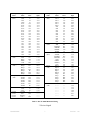
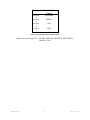
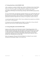
NEX-ISA
ISA Bus Support Users Manual
Including these Software Support packages:
ISA
Copyright © 2008 Nexus Technology, Inc. All rights reserved.
Contents of this publication may not be reproduced in any form without the written
permission of Nexus Technology, Inc.
Brand and product names used throughout this manual are the trademarks of their
respective holders.
ISA-MN-XXX
1
Doc. Rev. 1.10
Warranty Terms and License Agreement
For warranty terms, refer to the Terms and Conditions of Sale document that was included in the
product shipment. The Software License Agreement is displayed during installation. A hardcopy
of that agreement may be obtained from Nexus Technology.
All Nexus Technology products to which this manual refers are subject to the Terms and
Conditions of Sale document and the Software License Agreement, as appropriate.
Compliance with WEEE and RoHS Directives
This product is subject to European Union regulations on Waste Electrical and Electronics
Equipment. Return to Nexus Technology for recycle at end of life. Costs associated with the
return to Nexus Technology are the responsibility of the sender.
ISA-MN-XXX
2
Doc. Rev. 1.10
TABLE OF CONTENTS
1.0 OVERVIEW ........................................................................................................................... 4
1.1 General Information............................................................................................................ 4
2.0 SOFTWARE INSTALLATION ............................................................................................. 4
2.1 TLA600/700........................................................................................................................ 4
2.2 DAS9200............................................................................................................................. 5
3.0 CONFIGURING the NEX-ISA BUS ADAPTER .................................................................. 5
3.1 General Information............................................................................................................ 5
4.0 CONNECTING to the NEX-ISA ADAPTER ........................................................................ 5
4.1 General................................................................................................................................ 5
4.2 TLA600/700........................................................................................................................ 5
4.3 92A96.................................................................................................................................. 6
5.0 CLOCK SELECTION ............................................................................................................ 8
5.1 General Information............................................................................................................ 8
5.2 Clocking Options - Explanation ......................................................................................... 8
6.0 VIEWING DATA ................................................................................................................... 8
6.1 Viewing State Data on the TLA600/700 ............................................................................ 8
6.2 Viewing Timing Data on the TLA600/700....................................................................... 11
6.3 Viewing State Data on the DAS9200/TLA500 ................................................................. 12
6.4 Viewing Timing Data on the DAS9200/TLA500.............................................................. 12
APPENDIX A - Necessary Signals for Clocking ......................................................................... 13
APPENDIX B - Considerations.................................................................................................... 14
B.1 ISA Loading ..................................................................................................................... 14
B.2 "Patch" Areas ................................................................................................................... 14
B.3 Pattern Generation............................................................................................................ 14
APPENDIX C - ISA Bus Pinout................................................................................................... 15
APPENDIX D - NEX-ISA Silk Screen ........................................................................................ 16
APPENDIX E - Support ............................................................................................................... 17
APPENDIX F - References .......................................................................................................... 18
TABLE OF FIGURES
Figure 1- ISA State Display on TLA600/700 ................................................................................. 9
Figure 2- ISA MagniVu Display on TLA600/700........................................................................ 11
TABLE OF TABLES
Table 1- ISA TLA600/700/92A96 Wiring ..................................................................................... 7
Table 2- ISA_Cyc Cycle Type Symbol Table ................................................................................ 9
Table 3- ISA_Bus Bus Control Symbol Table ............................................................................. 10
ISA-MN-XXX
3
Doc. Rev. 1.10
1.0 OVERVIEW
1.1 General Information
The NEX-ISA adapter has been designed to provide quick and easy connections to interface a
102- or 136-channel TLA600/700, a 92A96, or a 92C96 acquisition module to an ISA backplane.
(The ISA designation refers to the Industry Standard Architecture specification, which is the
equivalent of the IBM PC XT/AT bus.) In addition, the method of connection permits the use of
other acquisition cards, pattern generation cards or other measurement devices such as
oscilloscopes.
The included software will permit the acquisition of ISA bus cycles, and will display the data in
easy-to-read symbolic form rather than raw hexadecimal or binary data.
Please note that this manual uses some terms generically. For instance, references to a 92A96
acquisition card apply to a 92C96 acquisition card; references to the DAS9200 apply equally to
the TLA500; and references to the TLA600/700 apply to a TLA704, 711, 714, 715, 720 or 721
chassis with one or more 7*3/4 acquisition cards.
Appendix D is a silk-screen print of the NEX-ISA Adapter board. Referring to this drawing
while reading the manual is suggested.
This manual assumes that the user is familiar with the ISA Bus specification and the Tektronix
TLA600/700, DAS9200, or TLA500 Logic Analyzer. Also, in the case of the TLA600/700, it is
expected that the user is familiar with Windows O.S.
For information on using a Prism 32GPX/GPD module with this support, or if 5¼" DAS floppies
are needed, please contact Nexus Technology. See Appendix F for contact information.
2.0 SOFTWARE INSTALLATION
One 3½” diskette has been included with the NEX-ISA Bus Adapter. It is for use with the
TLA600/700 series. Diskettes for the DAS9200 or TLA500 are available upon request. Please
see Appendix E for contact information.
2.1 TLA600/700
The ISA support software is loaded in the same method as other Win95 programs. Place the
NEX-ISA Install disk in the floppy drive of the TLA600/700. Select Control Panel and run
Add/Remove Programs, choose Install, Next, then Finish. Add/Remove will then run
SETUP.EXE on the floppy and install the support in its proper place on the hard disk.
ISA-MN-XXX
4
Doc. Rev. 1.10
To load a support into the TLA600/700, first select the desired Logic Analyzer card in the Setup
screen, select Load Support Package from the File pull-down, then choose ISA and click on
Okay. Note that for either support the Logic Analyzer card must be at least 102-channels in
width.
2.2 DAS9200
The included diskette should be loaded onto the DAS9200 using the Install Application
function. This function is available from the Disk Services menu of the DAS. For more
information, refer to the Tektronix DAS9200 or TLA500 System User's Manual.
Load the desired support from within the 92A96 Config menu by choosing "ISA Support” and
pressing <RETURN>. The channel grouping, clocking and symbols will then be loaded.
3.0 CONFIGURING the NEX-ISA BUS ADAPTER
3.1 General Information
There are two jumper areas on the NEX-ISA adapter board - JP1 and JP2. When using the NEXISA adapter in an 8-bit (XT) slot, shorting blocks must be placed across these two jumpers for
proper data acquisition by the logic analyzer. When using the adapter in a 16-bit (AT) slot, the
shorting blocks must be removed. If they are left on when using the NEX-ISA board in an AT
slot, improper operation of the target system may result.
4.0 CONNECTING to the NEX-ISA ADAPTER
4.1 General
Although taller than a standard XT or AT module, the NEX-ISA adapter is designed to plug
directly into any full-size ISA backplane slot. The board length and connector spacing conforms
to ISA specifications.
4.2 TLA600/700
When using NEX-ISA support with a TLA600/700 containing a 7*3/4 acquisition module, the
necessary acquisition data sections are A0-A3, D0-D3, and C0-C3. These grouped channels (8
podlets to a group) should be connected to the locations denoted for the A96. Follow the silkscreened information on the board that shows the proper relationship between the signal and
ISA-MN-XXX
5
Doc. Rev. 1.10
reference inputs. When properly connected, the sides of the podlets that have writing on them
should be visible.
Connect the four clock leads to their specified locations at J12 (the only connector with 4
locations). Again, follow the silk-screened information to properly connect the clock input and
its ground. Table 1 shows the wiring and Channel Grouping for the TLA600/700 when used with
the NEX-ISA adapter.
4.3 92A96
When using a 92A96 or 92C96, connect the grouped pods to their appropriate locations by
following the silk-screen information printed on the adapter board. The 92A/C96 pods are
labeled A0-A3, D0-D3, and C0-C3. Each pod has its proper location denoted on the silk-screen
of the adapter board. When attaching the pods, follow the silk-screen information on the board
showing the ground and signal pin locations. When properly connected, the colored sides of the
podlets should be visible.
Connect the four clock leads (one per A96 cable) to their specified locations at J12 (the only
connector with 4 locations). Again, follow the silk-screened information to properly connect the
clock input and its ground. Table 1 shows the wiring and Channel Grouping for the 92A96 when
used with the NEX-ISA adapter.
ISA-MN-XXX
6
Doc. Rev. 1.10
Group
Name
Address
(Hex)
Misc
(Off)
DMA_Req
(Off)
DMA_Ack
(Off)
MiscAddr
Clock:0
Clock:1
Clock:2
Clock:3
Signal
Name
LA23
LA22
LA21
LA20
SA19
SA18
SA17
SA16
SA15
SA14
SA13
SA12
SA11
SA10
SA9
SA8
SA7
SA6
SA5
SA4
SA3
SA2
SA1
SA0
RESET
AEN
BALE
SBHE
CLK
DRQ7
DRQ6
DRQ5
DRQ3
DRQ2
DRQ1
DRQ0
-DAK7
-DAK6
-DAK5
-DAK3
-DAK2
-DAK1
-DAK0
LA19
LA18
LA17
ISAWR
CLK=
ISAWR=
CLK==
ISA
Pin #
C2
C3
C4
C5
A12
A13
A14
A15
A16
A17
A18
A19
A20
A21
A22
A23
A24
A25
A26
A27
A28
A29
A30
A31
B2
A11
B28
C1
B20
D15
D13
D11
B16
B6
B18
D09
D14
D12
D10
B15
B26
B17
D8
C6
C7
C8
*
B20
*
B20
TLA700 / 92A96
input
A3:7
A3:6
A3:5
A3:4
A3:3
A3:2
A3:1
A3:0
A2:7
A2:6
A2:5
A2:4
A2:3
A2:2
A2:1
A2:0
A1:7
A1:6
A1:5
A1:4
A1:3
A1:2
A1:1
A1:0
C3:0
C1:5
C1:2
C1:1
C3:3
D0:6
D0:5
D0:4
D0:3
D0:2
D0:1
D0:0
D1:6
D1:5
D1:4
D1:3
D1:2
D1:1
D1:0
C2:7
C2:6
C2:5
-----------------
Group
Name
Data
(Hex)
CycType
(Sym)
BusCtrl
(Sym)
Intrpts
(Off)
Unused
(Off)
Signal
Name
SD15
SD14
SD13
SD12
SD11
SD10
SD9
SD8
SD7
SD6
SD5
SD4
SD3
SD2
SD1
SD0
-IOW
-IOR
-SMEMW
-SMEMR
-MEMW
-MEMR
T/C
-IOCHK
-REFRSH
-MASTER
-0WS
IORDY
-MEM16
-IO16
IRQ15
IRQ14
IRQ12
IRQ11
IRQ10
IRQ9
IRQ7
IRQ6
IRQ5
IRQ4
IRQ3
---------------------------------
ISA
Pin #
C18
C17
C16
C15
C14
C13
C12
C11
A2
A3
A4
A5
A6
A7
A8
A9
B13
B14
B11
B12
C10
C9
B27
A1
B19
D17
B8
A10
D1
D2
D6
D7
D5
D4
D3
B4
B21
B22
B23
B24
B25
-----------------
TLA700 / 92A96
input
D3:7
D3:6
D3:5
D3:4
D3:3
D3:2
D3:1
D3:0
D2:7
D2:6
D2:5
D2:4
D2:3
D2:2
D2:1
D2:0
C0:3
C0:2
C0:5
C0:4
C0:1
C0:0
C1:0
C1:6
C3:1
C1:7
C1:4
C1:3
C0:7
C0:6
C2:2
C2:1
C2:0
A0:7
A0:6
A0:5
A0:4
A0:3
A0:2
A0:1
A0:0
C3:7
C3:6
C3:5
C3:4
C2:4
C2:3
D1:7
D0:7
Table 1- ISA TLA600/700/92A96 Wiring
* Derived signal
ISA-MN-XXX
7
Doc. Rev. 1.10
5.0 CLOCK SELECTION
5.1 General Information
There are two clocking options available when using the NEX-ISA support package. Each is
explained in detail below.
When using a TLA600/700, the clocking mode is selected by moving to the System window,
clicking on Setup for the appropriate LA card, then clicking on More (a button to the right of the
Clocking field). Choose the desired mode in the Clocking Select field.
When using a DAS9200 or TLA500, the clocking selection is made in the Clock menu.
5.2 Clocking Options - Explanation
Cycle Acquisition Only - This is the default clocking selection. In this mode every bus
transaction is acquired. All Wait states are ignored. This clocking selection offers the best use of
your acquisition memory by ignoring all Wait states, and also provides more easily understood
data. For this acquisition mode to work properly, the ISA signals -MEMR, -MEMW, -IOR, IOW, -SMEMR, -SMEMW, and CLK must be present.
Every CLK Edge - In this mode, data will be acquired on every edge of the ISA CLK signal.
This clocking mode shows all bus cycles, including Wait states. Since no clocking qualification
is done only the CLK signal is required.
6.0 VIEWING DATA
6.1 Viewing State Data on the TLA600/700
After making an initial acquisition, the TLA600/700 will display the data in the Listing (State)
format. Address and Data information is displayed in hexadecimal format; Cycle Type
(CycType) and Bus Control (BusCtrl) data is displayed using symbols; Miscellaneous, DMA
Request and Acknowledge, Interrupts, and MiscAddr data groups default to OFF.
The use of Symbol Tables when displaying state data enables the user to quickly determine what
type of bus cycle was acquired. When using NEX-ISA, a symbol table (ISA_Cyc, Table 2) has
been provided to show the type of bus cycle that occurred on the ISA bus. This symbol table
quickly shows whether the acquisition was a memory or I/O operation, a read or a write, etc.
A second symbol table (ISA_BusCtrl, Table 3) shows whether the bus transaction was a Refresh
cycle, or an 8- or 16-bit operation.
ISA-MN-XXX
8
Doc. Rev. 1.10
It is important to note that changing the group, channel, or wiring of the CycType or BusCtrl
groups can result in incorrect symbol information being displayed.
Pattern
0xxxxx
x0xxxx
xx0xxx
xxx0xx
xxxx0x
xxxxx0
TLA700 / 92A96
Symbol
IOW
IOR
SMEMW
SMEMR
MEMW
MEMR
Table 2- ISA_Cyc Cycle Type Symbol Table
Signals, from left to right: -IOW, -IOR, -SMEMW, -SMEMR, -MEMW, -MEMR
Figure 1- ISA State Display on TLA600/700
ISA-MN-XXX
9
Doc. Rev. 1.10
Pattern
xx0xxxx
x
xx1xxx0
x
xx1xxxx
0
xx1xxx1
1
TLA700 / 92A96
Symbol
REFRESH
MEM16
IO16
8-BIT
Table 3- ISA_Bus Bus Control Symbol Table
Signals, from left to right: T/C, -IOCHK, -REFRSH, -MASTER, -0WS, IORDY,
-MEM16, -IO16
ISA-MN-XXX
10
Doc. Rev. 1.10
6.2 Viewing Timing Data on the TLA600/700
By default, the TLA600/700 will display an acquisition in the Listing (State) mode. However,
the same data can be displayed in Timing form by adding a Waveform Display window. This is
done by clicking on the Window pull-down, selecting New Data Window, clicking on
Waveform Window Type, then choosing the Data Source. Two choices are presented: ISA
and ISA-MagniVu. The first (ISA) will show the exact same data (same acquisition mode) as
that shown in the Listing window, except in Timing format. The second selection, ISAMagniVu, will show all of the channels in 2GHz MagniVu mode, so that edge relationships can
be examined at the module’s trigger point. With either selection, all channels can be viewed by
scrolling down the window. Refer to the TLA600/700 System User’s Manual for additional
information on formatting the Waveform display.
Figure 2- ISA MagniVu Display on TLA600/700
ISA-MN-XXX
11
Doc. Rev. 1.10
6.3 Viewing State Data on the DAS9200/TLA500
After an acquisition is made the DAS9200 Logic Analyzer will display the data in State Display
mode (as a default only). Address and Data information is displayed in hexadecimal format;
Cycle Type (CycType) and Bus Control (BusCtrl) data is displayed using symbols;
Miscellaneous, DMA Request and Acknowledge, Interrupts, and MiscAddr data groups default
to OFF.
The use of Symbol Tables when displaying state data enables the user to quickly determine what
type of bus cycle was acquired. When using NEX-ISA, a symbol table (ISA_Cyc, Table 2) has
been provided to show the type of bus cycle that occurred on the ISA bus. This symbol table
quickly shows whether the acquisition was a memory or I/O operation, a read or a write, etc.
A second symbol table (ISA_BusCtrl, Table 3) shows whether the bus transaction was a Refresh
cycle, or an 8- or 16-bit operation.
It is important to note that changing the group, channel, or wiring of the CycType or BusCtrl
groups can result in incorrect symbol information being displayed.
6.4 Viewing Timing Data on the DAS9200/TLA500
It may be useful to display acquired information using the Timing Diagram display of the
DAS9200. (Note that, unlike some other logic analyzers, with the DAS9200 there is no need to
re-acquire ISA data when changing from one display mode to another. The same data can be
viewed in either format.) This method of data display can be particularly useful when an
asynchronous acquisition has been made (using the DAS9200 internal acquisition clock) to
determine the relationships between signal edges.
Refer to the appropriate Tektronix DAS 92A96 Module User's Manual for more detailed
information on formatting the display of the acquired data.
ISA-MN-XXX
12
Doc. Rev. 1.10
APPENDIX A - Necessary Signals for Clocking
Because of the number of control signals defines in the ISA specification, additional circuitry
had to be provided to ensure proper clocking of data. A 74S30 8-input NAND gate is used to
gate -IOW, -IOR, -SMEMW, -SMEMR, -MEMW, and -MEMR to provide a logic high output
(ISAWR) whenever any one of these inputs goes low. This generated signal is what is used to
acquire information when in the “Cycle Acquisition Only” mode.
When acquiring data in “Acquire Every CLK Edge” mode, the only signal necessary for
clocking is CLK.
ISA-MN-XXX
13
Doc. Rev. 1.10
APPENDIX B - Considerations
B.1 ISA Loading
It must be noted that the NEX-ISA Bus Adapter does not provide any buffering of the ISA
backplane signals. This was a conscious design decision that was made by balancing the
tradeoffs of possible backplane loading versus signal acquisition accuracy. By not introducing
signal buffers it is possible, using the NEX-SIA adapter, to see the exact timing relationships and
signal waveforms from the backplane. It is also much easier to connect pattern generators to the
backplane since buffer direction is not a concern. It is believed that the signal loading of the
TLA600/700 or 92A96 acquisition cards is low enough so that ISA signal degradation will not
occur.
The NEX-ISA Adapter Board was designed so that the run lengths for critical signals (and those
with the highest activity levels, such as the address / data bus) are as short as possible. This
should help greatly in retaining signal integrity.
B.2 "Patch" Areas
If signal loading or reflection does become a concern, the capability exists to add series resistors
to any ISA signal. Patch areas have been provided next to each TLA600/700/A96 connector,
consisting of two rows of plated through holes. These areas (outlined on the silk-screen and
labeled as Nxx) are suitable for individual resistors or resistor networks. To add a series resistor,
simply cut the trace of the desired signal on the component side of the board, and solder the
resistor between the two feed-throughs.
B.3 Pattern Generation
Because there is no buffer circuitry on the NEX-ISA Adapter, it is well suited for use with the
92S16 and 92S32 Pattern Generator modules available for the DAS9200. By connecting pattern
generator probes to the A96 signal connectors on the Adapter, desired bus activity can be
simulated. This can be particularly effective when trying to debug interrupt or DMA conflicts.
It should be noted that, because of the pin spacing of the A96 connectors, it is not recommended
that the Tektronix P6464 or P6465 pattern generator probes be used without providing adequate
cooling for their podlets. These probes use active podlets that can get very warm in use. A better
choice would be the P6463 pods which are passive and do not have such cooling requirements.
ISA-MN-XXX
14
Doc. Rev. 1.10
APPENDIX C - ISA Bus Pinout
ISA-MN-XXX
Pin #
1
2
3
4
5
6
7
8
9
10
11
12
13
14
15
16
17
18
19
20
21
22
23
24
25
26
27
28
29
30
31
Side B - Solder Side
Ground
RESET
+5V
IRQ9
-5V
DRQ2
-12V
-0WS
+12V
Ground
-SMEMW
-SMEMR
-IOW
-IOR
-DAK3
DRQ3
-DAK1
DRQ1
REFRSH
CLK
IRQ7
IRQ6
IRQ5
IRQ4
IRQ3
-DAK2
T/C
BALE
+5V
OSC
Ground
Side A - Component Side
-IOCHK
SD7
SD6
SD5
SD4
SD3
SD2
SD1
SD0
IORDY
AEN
SA19
SA18
SA17
SA16
SA15
SA14
SA13
SA12
SA11
SA10
SA9
SA8
SA7
SA6
SA5
SA4
SA3
SA2
SA1
SA0
Pin #
1
2
3
4
5
6
7
8
9
10
11
12
13
14
15
16
17
18
Side D - Solder Side
-MEM16
-IO16
IRQ10
IRQ11
IRQ12
IRQ15
IRQ14
-DAK0
DRQ0
-DAK5
DRQ5
-DAK6
DRQ6
-DAK7
DRQ7
+5V
-MASTER
Ground
Side C - Component Side
SBHE
LA23
LA22
LA21
LA20
LA19
LA18
LA17
-MEMR
-MEMW
SD8
SD9
SD10
SD11
SD12
SD13
SD14
SD15
15
Doc. Rev. 1.10
APPENDIX D - NEX-ISA Silk Screen
ISA-MN-XXX
16
Doc. Rev. 1.10
APPENDIX E - Support
About Nexus Technology, Inc.
Established in 1991, Nexus Technology, Inc. is dedicated to developing, marketing, and
supporting Bus Analysis applications for Tektronix Logic Analyzers.
We can be reached at:
Nexus Technology, Inc.
78 Northeastern Blvd. #2
Nashua, NH 03062
TEL: 877-595-8116
FAX: 877-595-8118
Web site: http://www.nexustechnology.com
Support Contact Information
Technical Support
General Information
Quote Requests
[email protected]
[email protected]
[email protected]
We will try to respond within one business day.
If Problems Are Found
Document the problem and e-mail the information to us. If at all possible please forward
a Saved System Setup (with acquired data) that shows the problem. Do not send a text
listing alone as that does not contain enough data for analysis. To prevent corruption
during the mailing process it is strongly suggested that the Setup be zipped before
transmission.
ISA-MN-XXX
17
Doc. Rev. 1.10
APPENDIX F - References
Tektronix TLA600/700 System User’s Manual
Tektronix TLA600/700 Logic Analyzer User’s Manual
Tektronix DAS9200 / TLA500 System User’s Manual
Tektronix 92A96 / 92C96 Module User’s Manual
“AT Bus Design” by Edward Solari
Published by Annabooks, San Diego, CA
“Intel ISA Bus Specification and Application Notes”
Rev. 3.00, January 30, 1990
“Personal Computer Bus Standard”
IEEE document P996
Draft D2.02, 13 July 1990
ISA-MN-XXX
18
Doc. Rev. 1.10