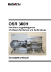
1
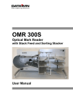
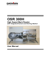
OSR 300H
High Speed Mark Reader
with Integrated Camera and Sorting Stacker
User Manual
Publisher:
DATAWIN GmbH
Etzstrasse 37
D-84030 Ergolding
Tel. :
+ 49 (0)871-43 05 99 0
Fax:
+ 49 (0)871-43 05 99 29
Email: [email protected]
Web: http://www.datawin.de
Printed in Germany
Subject to alteration
Windows is a registered trademark of the Microsoft Corporation.
Copyright © DATAWIN GmbH
All rights reserved
This manual is the intellectual property of DATAWIN GmbH.
Unauthorized use, duplication or distribution is prohibited.
Any reproduction of the contents of this manual, in whole or in part, without written permission of DATAWIN
GmbH is forbidden.
Edition September 2006/1.2
DATAWIN GmbH
OSR 300H – User Manual
2
Table of Contents
1
1.1
1.1.1
1.2
1.2.1
1.3
1.3.1
1.3.2
1.3.3
Introduction .................................................................................................... 1-1
About this manual............................................................................................. 1-1
Typographical notes ......................................................................................... 1-1
Information about unpacking the mark reader................................................... 1-2
Scope of the delivery ........................................................................................ 1-3
Device related safety information...................................................................... 1-4
Conformity ........................................................................................................ 1-4
Precautionary measures for transportation, storage and installation ................. 1-4
Selection of the work site.................................................................................. 1-5
2
2.1
2.2
2.2.1
2.2.2
2.2.3
2.2.4
2.2.5
2.2.6
2.2.7
2.2.8
The OSR 300H scanner and mark reader...................................................... 2-1
Functional components..................................................................................... 2-1
Document processing – from intake to output ................................................... 2-3
Automatic document intake............................................................................... 2-3
Document transport path .................................................................................. 2-4
Camera system ................................................................................................ 2-6
OMR read head ................................................................................................ 2-7
Bar code read head .......................................................................................... 2-7
MICR module.................................................................................................... 2-7
LED display and tray button.............................................................................. 2-8
Optional printer ................................................................................................. 2-8
3
3.1
3.2
3.2.1
3.2.2
3.3
3.4
3.5
3.5.1
3.5.2
3.6
3.6.1
3.6.2
3.6.3
3.7
3.7.1
3.7.2
3.7.3
3.8
Preparing and installing the reader............................................................... 3-1
Attaching the inclined adjustable feet................................................................ 3-1
Attaching the document stoppers ..................................................................... 3-2
Intake tray......................................................................................................... 3-2
Output trays...................................................................................................... 3-2
Inserting ink cartridges in the (optional) printer ................................................. 3-3
Mains connection data...................................................................................... 3-3
Interfaces.......................................................................................................... 3-4
USB interface ................................................................................................... 3-4
Serial interface.................................................................................................. 3-4
PC connection .................................................................................................. 3-4
Minimum requirements on the PC..................................................................... 3-4
Installing the software ....................................................................................... 3-4
Connecting the reader and the PC.................................................................... 3-4
Testing the read functions ................................................................................ 3-5
Camera test...................................................................................................... 3-5
OMR test .......................................................................................................... 3-5
Starting the read process.................................................................................. 3-5
De-installing the reader..................................................................................... 3-6
4
4.1
4.2
4.2.1
Operation of the reader .................................................................................. 4-1
Loading the stack of documents ....................................................................... 4-1
Starting the read process.................................................................................. 4-2
Display of the operating status.......................................................................... 4-2
DATAWIN GmbH
OSR 300H – User Manual
3
4.3
4.3.1
4.3.2
4.4
Eliminating document jams ............................................................................... 4-3
Opening and closing the scanner cover ............................................................ 4-3
Removing documents ....................................................................................... 4-4
Trouble shooting............................................................................................... 4-5
5
5.1
5.1.1
5.1.2
5.1.3
5.1.4
5.2
5.3
5.3.1
5.4
5.5
5.5.1
5.5.2
5.5.3
5.5.4
5.5.5
Setting, adjusting and cleaning the reader ................................................... 5-1
Setting the OMR read head .............................................................................. 5-1
Basic setting "standard document" ................................................................... 5-1
Adjusting the lateral setting of the OMR read head........................................... 5-2
Adjusting the lateral setting of the lower OMR read head (option) .................... 5-3
Effect of the read head setting on the scanning result....................................... 5-4
Setting the bar code read head (option)............................................................ 5-5
Setting the document isolation.......................................................................... 5-6
Cleaning the separating belt ............................................................................. 5-7
Replacing ink cartridges in the printer............................................................... 5-8
General information on cleaning the OSR 300H ............................................. 5-10
Cleaning the transport rollers.......................................................................... 5-11
Cleaning the light barriers............................................................................... 5-11
Cleaning the read windows (camera, OMR and bar code) .............................. 5-11
Cleaning the MICR module (option)................................................................ 5-11
Cleaning the housing surface ......................................................................... 5-12
6
6.1
6.2
6.2.1
6.2.2
6.2.3
6.2.4
6.3
6.3.1
6.3.2
6.3.3
6.3.4
Requirements on the documents .................................................................. 6-1
External characteristics..................................................................................... 6-1
Prescriptions and recommendations concerning OMR marks........................... 6-2
The mark field................................................................................................... 6-2
Correct marks................................................................................................... 6-3
Inadmissible marks........................................................................................... 6-3
Reliable marking instruments............................................................................ 6-4
DATAWIN OMR document specifications ......................................................... 6-5
Standard document .......................................................................................... 6-5
Scanning window.............................................................................................. 6-7
Bar codes labels and imprints........................................................................... 6-8
Permissible document colors for red light and infrared light scanning ............... 6-9
DATAWIN GmbH
OSR 300H – User Manual
4
1 Introduction
1.1 About this manual
This manual is intended for users who are entrusted with the setting up,
installation and operation of the OSR 300H optical mark reader (OMR = Optical
Mark Recognition).
• Part 1 provides information about
– unpacking and storing the device and device related safety information
– connection to the mains source and authorization as well as
– the requirements on the operating environment.
• Part 2 informs you about
– the most important functional components, their designations and
arrangement as well as
– the main mode of operation.
• Part 3 describes
– the preparations for initial operation and also
– the installation of the OSR 300H - from connection to the PC up to
conducting a test run.
• Part 4 provides tips and information to facilitate faultless operation of the
OSR 300H.
• Part 5 shows how you can increase the reading reliability:
– by mechanical adjustments in the reader and
– by a simple cleaning procedure of the OSR 300H.
• Part 6 contains the document specifications and information on the marks.
1.1.1 Typographical notes
Ị
This symbol calls your attention to particular items that absolutely must be
observed.
♦ This symbol always appears before process sequences and it simultaneously
indicates the chronological sequence.
DATAWIN GmbH
OSR 300H – User Manual
1-1
1.2 Information about unpacking the mark reader
The reader lies with its back side
towards the bottom inside the
packaging. The accessories are to be
found in the separate packaging.
♦ Lift the cover along with the
attached filling materials vertically
out of the packaging.
♦ Tip the box carefully onto its side
so that the reader is standing on its
adjustable feet. Now grasp the
reader by its feet and pull it out of
the box along with the filling
materials.
Ị
When carrying the reader as well, it
is best to grasp it only by the
adjustable feet.
The device weighs about 24 kg.
♦ Remove the transportation lock of
the camera and the two foamed
strips in the output trays.
DATAWIN GmbH
OSR 300H – User Manual
1-2
Ị
Save the entire original packing for later transportation and shipping of the
mark reader and the sorting stacker.
Devices that are sent back to suppliers for maintenance or repair work are
always returned in their original boxes (possibly at cost of the sender).
1.2.1 Scope of the delivery
Check to make sure that the delivery is complete. All accessories required for the
connection and operation of the OSR 300H are included in the delivery:
–
–
–
–
mains cable
data cable
tools
CD ROM with installation software and manual
If something is missing or if damages occurred during transportation, please
contact your supplier.
DATAWIN GmbH
OSR 300H – User Manual
1-3
1.3 Device related safety information
1.3.1 Conformity
The OSR 300H reader conforms to the CE standards and guidelines for data
processing devices (design according to VDE 0805/5.90, interference
suppression according to VDE 0871-B). It can be operated continuously under
normal room conditions.
1.3.2 Precautionary measures for transportation, storage and installation
Please observe the following points regarding the transportation and installation
of the reader:
Transportation and storage
Ị
Transportation of the reader should only be effected in the original packing. It
protects against shocks and inadmissible strains on the mechanical parts.
Ị
Please take the ambient conditions into consideration when transporting or
storing the reader.
Mains connection and authorization
Ị
The reader may only be operated when connected to a grounded shockproof
outlet. Industrially operated mains networks often exhibit substantial, loaddependent interference peaks (powerful motors, electrical welding plants, etc.).
The OSR 300H reader is protected against such interference to a great extent,
but if interference is present, try to use a network used for EDP or select a
mains supply that is free of interference.
Ị
Make sure that the mains voltage that is present corresponds to the required
values stated on the type plate.
Ị
Never open the housing of the reader and never remove any housing parts.
Ị
Always turn the reader off via the mains switch before carrying out any
adjustments or cleaning operations.
Ị
It is forbidden to effect changes or modifications to the reader that are not
stated in this manual. The manufacturer of the device will decline any form of
guarantee demand and will not accept any service clauses if it can be
demonstrated that the reader was manipulated or damaged by unauthorized
persons.
DATAWIN GmbH
OSR 300H – User Manual
1-4
1.3.3 Selection of the work site
Take care to assure that the OSR 300H is exposed to appropriate operating
conditions. This is important in assuring faultless functioning of the reader:
Ị
The reader must stand on a stable, horizontal and level surface. Its dimensions
are 630 x 360 x 300 (L x W x H in mm); the reader weighs about 24 kg.
Vibrations at the work site should be avoided.
Ị
The permissible ambient temperature for operation of the reader is +10° C to
+40° C (50° F to 104° F). Therefore, check to assure that the device is shielded
against sources of heat such as direct sunlight, radiators, spotlights or other
sources of light that produce heat.
Sunlight or foreign sources of light applied to the scanning unit under
unfavorable circumstances may also have an influence on the read sensitivity.
Ị
The permissible relative humidity amounts to 40 - 60%, condensation-free.
Ị
It must be possible to lay all cables (mains cable and data cable) without
buckling and without tensile stress. Take care to identify stumbling pitfalls.
Ị
The OSR 300H corresponds to the requirements regarding interference
emission and resistance to jamming (ESD) as specified by the CE guidelines.
In order to assure complete interference immunity, shielded data cables with
connector casings of metal or with metallic connector casings must be used.
Ị
Take care that the device is not operated in surroundings that are
contaminated by dust or oil. Air currents caused e. g. by windows that are
continually left open, by passageways or ventilators, may lead to the increased
production of dust and this in turn may necessitate shorter maintenance and
cleaning intervals.
Ị
The work site must afford sufficient space for the handling of the documents.
DATAWIN GmbH
OSR 300H – User Manual
1-5
2 The OSR 300H scanner and mark reader
This chapter provides information about the most important system components,
their designations and arrangement and describes the basic mode of operation.
The uniform designation employed here in the description of the individual
components of the reader will simplify understanding of the technical processes,
of the operation of the device and of the maintenance work.
2.1 Functional components
The OSR 300H mark reader is a scanner and OMR optical mark reader with
stack feed and two sorting stacker trays. It was designed as a high-capacity
reader with the greatest possible operating ease for efficient data input. As
options, the device can be equipped with
• a second OMR read head for the simultaneous reading of the front and rear
sides of a document,
• a two-line bar code read head adjustable across the entire width of the
document,
• an MICR module (then without the OMR read head)
• an ink jet printer (HP ink jet printer),
• a multiple line display for user guidance.
The two following figures show the components of the reader that are most
important for operation.
6
4
3
5
1
2
11
7
8
9
10
DATAWIN GmbH
OSR 300H – User Manual
2-1
1
2
3
4
5
6
7
8
9
10
11
12
13
14
15
16
17
Button for the document intake tray
Display of the operating status
Document intake tray
Feed rollers
Automatic document intake
Upper scanner cover
Curved baffle plate
Optional printer
Sorting deflector
Adjustable document stoppers
Document output trays
Intake roller
Separating belt
Transport rollers
OMR read window
Bar code read window
Camera window
This figure shows the OSR 300H reader with opened scanner cover:
15
17
16
14
12
13
DATAWIN GmbH
OSR 300H – User Manual
2-2
2.2 Document processing – from intake to output
2.2.1 Automatic document intake
The documents are automatically fed in from a stack on the document intake
tray. The topmost sheet is thereby "pulled off". A special intake system consisting
of three feed rollers, one intake roller and a reverse belt, the so-called separating
belt, assures the safe "isolation" of the documents. All the rollers are fitted with
silicone rings.
The three feed rollers are positioned at a slight slant to the feed direction and
they thus bring the top document into a position pressing against the back
stopper. You can set the interval between the separating belt and the intake roller
according to the thickness of the documents in use.
DATAWIN GmbH
OSR 300H – User Manual
2-3
The presence of documents in the intake tray is monitored by a light barrier.
When the reader starts operation the intake tray moves upwards and the light
barrier is queried. Only if at least one document is present in the intake tray is the
document transport started. (If the intake tray is empty, it moves down to the
bottom again.) A second light barrier is responsible for double document
detection. After the last document has been processed, the read process is
stopped and the intake tray moves down to the bottom again.
2.2.2 Document transport path
The documents that are drawn in individually are moved across transport rollers
whereby they successively pass the read stations and the camera system. The
transport speed amounts to up to 1.2 m/s, the read rate lies at a max. of 6,000
DIN A4 documents/hr.
In order to monitor the positions of the individual documents, the entire transport
path is equipped with light barriers.
The figure shows the transport path of the documents in the OSR 330H.
DATAWIN GmbH
OSR 300H – User Manual
2-4
After the documents have passed the read station, the camera, the curved baffle
plate and the printer they are deposited in one of the output trays.
Upper output tray
Lower output tray
The selection of the output tray is defined in the application program, e. g.: the
documents that have been read are placed in the lower output tray, whereby
documents with a poor read result - controlled by the sorting deflector - are
deposited in the upper output tray (the "bad" tray).
Sorting deflector
DATAWIN GmbH
OSR 300H – User Manual
2-5
2.2.3 Camera system
A high-resolution color camera with integrated optics and object illumination
above the paper path scan the front side of the document. Depending upon the
scanning application (software), the resolution amounts to 150 dpi or 300 dpi,
without compression or as JPEG; the compression takes place in the scanner.
Camera window
Either color images or alternatively gray scale images as well as binary images
are scanned from the front side of the document. In addition, clipped images
(snippets) from the front side are also possible.
Scanning is effected with 24-bit color depth.
DATAWIN GmbH
OSR 300H – User Manual
2-6
2.2.4 OMR read head
Upper read station
Depending upon the requirements of the
application, the OMR scanning can be
designed with infrared or with red light, the
mark density amounts to 40 tracks (1/5"
interval) or 48 tracks (1/6" interval). To protect
against dirt, the scanning strip is located
behind a read window.
The scanning strip can be adjusted laterally
within a certain tolerance range to
compensate for deviations in dimension of the
document mark (see section 5.1).
The figure shows the OSR 300H with two
OMR read heads to enable reading of the
front and rear sides of a document in one run.
2.2.5 Bar code read head
In connection with each OMR read head of
the OSR 300H, one bar code read head can
be installed as option, as desired for the front
side and/or rear side of the document. The
read head can be set to cover the entire width
of the document (see section 5.2). To protect
Bar code
against dirt, the read head is located behind a read window
read window.
OMR read window
2.2.6 MICR module
The optionally integrated MICR module
(MICR = magnetic ink character recognition)
reads documents with magnetic fonts, such
as e. g. CMC7 or E13B. The MICR module is
situated in the upper transport path right
behind the document intake. The module
consists of a unit for the magnetic biassing of
the characters and of the MICR read head.
MICR technology is predominantly used to
code bank checks. The read result is made
available to the host PC in the form of a data
record and can e. g. also be used as sorting
criterion for the output tray control in the
scanner.
DATAWIN GmbH
OSR 300H – User Manual
Lower read station
2-7
The MICR area that is to be read is parameterized via the scan program. You
can find more information on the scan program in the respective manual.
MICR read head
Unit for the
magnetic biassing
of the characters
Section 5.5.4 provides details on how to clean the MICR module.
2.2.7 LED display and tray button
Two control lamps show the operating status of the
reader (see section 4.2.1). The button enables
manual control of the document intake tray.
2.2.8 Optional printer
As an option it is possible to integrate an ink jet printer in the reader. The type
used is an HP ink jet printer. The installation position is located in the lower
transport path next to the curved baffle plate.
The printer is designed for alphanumeric character output with a density of up to
8 characters/25.4 mm and up to 50 characters per document. The printout is
DATAWIN GmbH
OSR 300H – User Manual
2-8
produced on the rear side of the document. The information to be printed, e. g. a
document number or the designation of the processing procedure, is
parameterized in the application program. Further information on the application
program is to be found in the corresponding manual.
Information on how to exchange ink cartridges is contained in section 5.4.
DATAWIN GmbH
OSR 300H – User Manual
2-9
3 Preparing and installing the reader
This chapter describes how to prepare the reader for initial operation and how to
proceed with the installation - from connection to a host (PC) up to conducting a
test run.
3.1 Attaching the inclined adjustable feet
You can improve document guidance in the OSR
300H reader if you set it up so that it is not completely
level on the work surface, but rather slightly inclined
toward the back. For this purpose two spacers are
included in the delivery that you can insert into the
corresponding bore holes at the front bottom side of
the two adjustable feet.
♦ Lift the reader slightly at the front by the
adjustable feet, “feel” for the bore hole and
insert a spacer into the bore hole of each foot
until it doesn’t fall out again.
♦ Then set the reader down again on the
adjustable feet and press uniformly on
both feet until the spacers are inserted
up to the limiting position in the bore
holes.
DATAWIN GmbH
OSR 300H – User Manual
3-1
3.2 Attaching the document stoppers
To ensure proper feeding in and depositing of the documents, you must set the
document stoppers to correctly correspond to the size of the documents to be
used before you start operation of the reader.
Ị
Please take care to observe the following adjustment criteria.
3.2.1 Intake tray
Ị
Both stoppers on the intake tray must lie flush against the stack of
documents, but they may not impede document intake.
♦ Place a stack of documents in the
intake tray and loosen the stoppers
by means of the knurled screws,
adjust the stoppers to accommodate
the size of the documents to be
processed and then fasten them
again.
Knurled screw
e. g. for large documents...
... or for smaller documents:
3.2.2 Output trays
Ị
The stoppers on the output trays should be positioned at an interval of
about 1 to 2 cm from the documents. The documents that are output
must be able to fall "freely" onto the output stack.
♦ Place a stack of documents in each
respective output tray and adjust the
document stoppers accordingly.
DATAWIN GmbH
OSR 300H – User Manual
3-2
♦ In order to limit the ejection of the documents in the output trays, push the
respective black stoppers accordingly and set them so that here as well the
documents only have 1 to 2 cm play.
Tip: These stoppers can only be pushed easily against frictional resistance if you
grasp them as far as possible near the top.
3.3 Inserting ink cartridges in the (optional) printer
If your OSR 300H is equipped as an option with a printer, you must insert an ink
cartridge before initial operation. Use ink cartridges from HP (HP51604A) or other
cartridges compatible to these.
You can read about how to insert or exchange the cartridges in section 5.4.
3.4 Mains connection data
The power supply of the OSR 300H is designed for the following voltage and
frequency ranges:
• Power supply:
230 V, 50 Hz (0,6 A)
115 V, 60 Hz (1,2 A)
• Current consumption:
max. 120 W
(with all options)
Normally no special provisions or settings of the voltage supply are required for
the operation of the OSR 300H. However, check whether the existing mains
voltage actually corresponds to the values on the type plate of the reader.
DATAWIN GmbH
OSR 300H – User Manual
3-3
3.5 Interfaces
3.5.1 USB interface
The data exchange between the OSR 300H and the PC is handled via a USB 2.0
interface. The USB connector is to be found on the rear panel of the device.
3.5.2 Serial interface
The serial interface of the reader (sub D socket) is used on the OSR 300H for
testing purposes only.
3.6 PC connection
3.6.1 Minimum requirements on the PC
•
•
•
•
•
•
•
processor: Pentium III processor, 500 MHz or higher
Microsoft Windows 2000/XP
screen resolution XGA (1024 x 768) or SXGA (1280 x 1024)
USB 2.0 interface
working memory: 256 MB RAM or more
hard disk memory: 4 GB or more
CD drive
3.6.2 Installing the software
Descriptions on installing the software (universal scanner interface [USI] and the
scan program) on the PC are contained in separate manuals. There you will find
detailed information about how to proceed with the set-up of the scanning
parameters and what parameterization possibilities are available in connection
with the OSR 300H. The read software defines the processing of the OMR marks
and bar codes that are read out on the PC. This program is always adapted
specifically to the respective application of the OSR 300H.
The manual presupposes that the user has knowledge of the Windows
environment along with its control menus and commands via mouse and
keyboard.
3.6.3 Connecting the reader and the PC
♦ Run down the operating system of the PC.
♦ Connect the USB cable to the USB socket
of the PC and to the USB socket of the
scanner.
USB connector
DATAWIN GmbH
OSR 300H – User Manual
3-4
Ị
Do not connect the reader to the
PC via the serial interface (sub D
socket).
♦ Connect the mains cable to the
connector of the scanner and then
plug the mains plug into a mains
outlet.
Mains switch
Mains plug
(Sub D socket)
♦ Turn on the reader by means of
the mains switch.
♦ Turn on the PC and run up the
operating system.
3.7 Testing the read functions
3.7.1 Camera test
Upon completion of the installation steps the scanner is ready for operation and
you can test the scanning of the documents. Check thereby if the scanner
operates faultlessly and if all the functions are executed in accordance with the
intended practical usage.
The manual of the DATAWIN scanning program contains tips and tricks to help
you obtain good scanning results fast.
3.7.2 OMR test
Conduct the test only with documents that you will actually use in practical
operation. In this regard, also note the document specifications contained in
section 6.3.
The special test program "OMR-Test" is also at your disposal for certain tests and
functional settings of the reader. The method of operation of this test program is
described in the "OSR 300H Technical Operating and Service Manual".
3.7.3 Starting the read process
♦ Insert a sufficient number of test documents.
♦ Start the read process from the PC.
The stack of documents will automatically be raised to the proper intake height
and the first document will be drawn in.
Ị
Since the documents are drawn in from the top, please do not insert more
documents while the read process is in progress.
After the last document, the read process will terminate autonomously and the
intake tray will be run down to the bottom position.
DATAWIN GmbH
OSR 300H – User Manual
3-5
3.8 De-installing the reader
♦ De-install the scanner software on the host PC if it is present.
♦ Run down the operating system of the PC.
♦ Turn off the reader.
♦ Loosen and unplug the connectors of the USB 2.0 data cable at the PC and at
the scanner.
♦ Unplug the connectors of the reader mains supply cable.
If the device is to be prepared for transportation:
♦ Remove the ink cartridge from the printer (see section 5.4).
DATAWIN GmbH
OSR 300H – User Manual
3-6
4 Operation of the reader
This chapter provides you with tips and information to assure faultless operation
of the OSR 300H.
4.1 Loading the stack of documents
After the reader has been turned on and the last document processed, the
document intake tray runs down to the lowest position so that documents can be
inserted. You can also run the stacker tray upwards or downwards alternately by
pressing the tray button.
♦ Take a properly aligned stack of documents (approx. 100 sheets) and place it
in the intake tray so that it is flush at the left and at the back sides of the
housing.
Tray button
The document intake tray can accommodate up to 500 sheets (80 g/m²); the
height of the stack, however, should not noticeably cause the pair of feed
rollers to be raised.
DATAWIN GmbH
OSR 300H – User Manual
4-1
4.2 Starting the read process
♦ Start the read process from the PC.
The stack of documents will automatically be raised to the proper intake height
and the first document will be drawn in.
Ị
Since the documents are drawn in from the top, please do not insert more
documents while the read process is in progress.
After the last document, the read process will terminate autonomously and the
intake tray will be run down to the bottom position.
4.2.1 Display of the operating status
The following table shows the standard displays:
LED
Significance
Red
Green
steady-burning
steady-burning
Power on
Before initialization.
blinking
steady-burning
At the end of initialization (approx. 20 sec. after
pressing the mains switch).
off
steady-burning
Ready
After insertion of documents and enabling by the tray
button.
Ị
Both LEDs blinking
simultaneously
An output tray is full; (blinking until the stack has
been removed; acknowledge by the tray button).
Both LEDs blinking
alternately
Transportation fault, document intake or ejection jam
or double document; (blinking until the fault has been
eliminated; acknowledge by the tray button).
It is possible that other operating modes or display statuses are parameterized
by the application software. In that case, they are documented in a special
software description.
DATAWIN GmbH
OSR 300H – User Manual
4-2
4.3 Eliminating document jams
The faultless isolation of the documents and their correct feeding in is monitored
by light barriers. This prevents two documents from being drawn in at the same
time.
In the transportation path as well, the position of the documents is determined
and monitored by light barriers. If a document gets jammed in the paper pathway
during transportation, this is detected by the missing presence of the document at
the corresponding light barrier and the read process is interrupted.
Reasons for document jamming may be e. g. very wrinkled, glued together or
soiled documents. Always eliminate the disturbance by carefully removing the
jammed document or foreign object (e. g. paper clip or shredded paper particles).
4.3.1 Opening and closing the scanner cover
♦ Grasp the scanner cover at the front document intake area and lift it upwards.
Fold the cover towards the back until it comes to rest on the housing.
♦ To close it again, swing the scanner cover forwards, until it is clear that the
guide pin of the base plate has locked into place.
Ị
Please do not allow the cover to fall backwards onto the housing when opening
it, nor to fall forwards onto the base plate when closing it.
DATAWIN GmbH
OSR 300H – User Manual
4-3
4.3.2 Removing documents
♦ Carefully remove all documents that are located in the paper pathway and
ascertain the cause of the document jam (e. g. wrinkled document, dog-ears,
poorly glued bar code label).
♦ When possible, always remove the document in the direction of the transport
path. If necessary, turn the double intake roller with your thumb and pull the
respective document carefully out of the transport roller towards the front; the
other transport rollers will move accordingly.
Ị
Pulling jammed documents in the direction opposite to that of the transport
path may cause them to be damaged by guide plates that are designed for
forward movement.
♦ Replace in the intake tray the documents caught in the jam and possibly any
other documents to be fed in and restart the read process.
DATAWIN GmbH
OSR 300H – User Manual
4-4
4.4 Trouble shooting
Problems that may possibly arise are listed in the following table. The measures
described often help to eliminate the errors.
Problem
Measure
OMR read errors
Recognition of the marks is becoming
increasingly poorer
♦ Check if the scanner is dirty.
If necessary, clean the covers
(protective glass covers) of the read
heads (see section 5.5.3).
♦ Check if the lateral setting of the
scanner is correct or if it possibly should
be adjusted (see section 5.1).
Marks are partially not recognized,
especially at the beginning and/or end of
the document
♦ Check if the edges of the documents are
straight.
Marks are recognized at places where
there are no marks, especially at the
beginning and/or end of the document
♦ Check if the edges of the documents are
straight.
♦ Check if the transport rollers are dirty
(see section 5.5.1).
♦ Check if the transport rollers are dirty
(see section 5.5.1).
Document transport
No documents are drawn in
♦ Open the scanner cover and check the
transport path. Remove any foreign
objects without force.
♦ Smooth out the document and flatten
down dog-ears if applicable.
♦ Check if bar code labels are not properly
glued or if they are turned up at the
corners.
♦ Check whether the application software
is running. Is the feed-in command from
the PC missing or was the data of a
document previously read not called?
♦ Turn the reader off and after about 3
sec. turn it on again. Start the PC again
according to the software description.
The document is drawn in but is not
scanned completely.
The ejection behavior is not defined.
DATAWIN GmbH
♦ Check if the transport rollers are dirty
(see section 5.5.1).
♦ Contact your supplier if you are using
documents that have clock marks that
are wider than those prescribed and that
thus do not correspond to the document
specification.
OSR 300H – User Manual
4-5
Problem
Measure
Document output
If none of the measures described above
The document is drawn in correctly, the
read data is transmitted to the PC, but the have helped:
reader does not output the document. Only ♦ Clean all the light barriers in the
after a document has been removed
transport path (see section 5.5.2).
manually is the next document drawn in.
♦ Check if the interface cable is firmly
connected.
If these measures still do not remedy the
situation:
♦ Please contact DATAWIN:
Hotline: +49 17 33 87 45 27
Fax:
+49 871 43 05 99 29
Email: [email protected]
DATAWIN GmbH
OSR 300H – User Manual
4-6
5 Setting, adjusting and cleaning the reader
This chapter describes how you can set the read stations by means of simple
mechanical adjustments to correspond to the documents to be read. Moreover,
you will learn how to set the document isolation and how to clean the device
without great effort to increase the read accuracy. For these operations you will
need a cross-tip screwdriver (size 1, 300 mm) as well as two hexagon socket
screw keys (1.5 and 2.5 mm). These tools are included in the scope of delivery of
the OSR 300H.
5.1 Setting the OMR read head
In the manufacture and printing of mark documents a particular dimensional field
must be exactly adhered to. Besides this, the clock mark track and the marking
area must run exactly parallel to the edge of the document that is transported
along the document stopper during the read process. On documents that are
printed or cut askew, the clock mark track and the marking area are spread
across the entire document outside of the dimensional field. These deviations in
dimension can be compensated within a certain tolerance range by means of a
lateral “shifting” of the OMR scanning strip.
5.1.1 Basic setting "standard document"
The mark scanning is set at the factory to correspond to a "standard document".
The table below shows the distances (in mm) based on a sample of 40 track
scanning with mark spacing of 1/5". The dimensions A and H are decisive for the
correct lateral setting of the OMR read head. When these dimensions, due to
inaccurate printing or cutting of the documents, are smaller or larger (deviations
max. -1 to +3 mm), compensation can be achieved by corresponding adjustment
Document stopper
min.
13.97
B
5.08
C
10
D
1
E
1.5
F
G
DATAWIN GmbH
OSR 300H – User Manual
norm.
A
max.
4
3.0
10
H
7.62
I
5.08
5-1
The read head must be adjusted when marks on the document (even quite solid
marks) that do not fill out the entire width of the mark field, are not scanned at all
or are only scanned in an inaccurate manner. It is also typical that marks are
recognized although they are actually too short or are situated clearly off-center
in the mark field.
5.1.2 Adjusting the lateral setting of the OMR read head
♦ Open the scanner cover.
The position at which the document
stopper is located during the read
process is designated by a reference
line on the base plate of the read head.
On the front side of the scanner cover
there is an opening for the setting
screw of the scanning strip.
♦ Insert the hexagon socket screw key
into the opening and turn it
–
clockwise: the scanning strip is set
further away from the edge of the
document (edge with the clock mark),
that is, away from the reference line.
–
counter-clockwise: the scanning strip
is set closer to the edge of the
document (edge with the clock mark),
that is, closer to the reference line.
Reference line
With one rotation of the hexagon socket
screw key the scanning strip is shifted
by 0.5 mm in the respective rotational
direction.
Additional information about adjusting
the scanning strip is to be found in section 5.1.4 “Effect of the read head
setting on the scanning result”.
♦ Subsequently conduct a
test run with original
documents to check the
setting of the read head.
Clock track
Reference line
DATAWIN GmbH
OSR 300H – User Manual
5-2
5.1.3 Adjusting the lateral setting of the lower OMR read head (option)
♦ Open the scanner cover.
At the front of the lower scanner cover there is also an opening for the setting
screw for the adjustment of the scanning strip:
Hexagon socket screw key
♦ Insert the hexagon socket screw key into the opening and turn it
–
clockwise: the scanning strip is set further away from the edge of the
document (edge with the clock mark), that is, away from the reference line.
–
counter-clockwise: the scanning strip is set closer to the edge of the
document (edge with the clock mark), that is, closer to the reference line.
With one rotation of the hexagon socket screw key the scanning strip is shifted
by 0.5 mm in the respective rotational direction. Additional information about
adjusting the scanning strip is to be found in section 5.1.4 “Effect of the read
head setting on the scanning result”.
♦ Subsequently conduct a test run with original documents to check the setting of
the read head.
DATAWIN GmbH
OSR 300H – User Manual
5-3
5.1.4 Effect of the read head setting on the scanning result
On the basis of examples of various mark types and mark positions the following
table shows how the scanning result is dependent upon the lateral setting of the
read head. The test points (examples 4, 5, 6, 7) are also to be found on the
DATAWIN test document, with the aid of which you can quickly obtain information
about the setting of the read head and accordingly correct the setting of the
scanning strip.
Marking examples:
Document edge (reference line)
Clock mark track
A*
B*
Scanning
strip is set
correctly.
Comments on the marking
Interval from
Interval from
scanning strip to scanning strip to
reference line
reference line too
too slight for
large for
document
document
Scanning
1
Correct
Accurate
Accurate
Accurate
2
Correct
Accurate
Accurate
Accurate
3
Correct
Accurate
No
No
4
Test point: middle
Accurate
No
No
5
Test point: lower edge
No
No
Yes
6
Test point: upper edge
No
Yes
No
7
Test point: upper & lower edges
No
Yes
Yes
8
Sloppy, bleeding mark
Inaccurate
No
Inaccurate
9
Bleeding mark
Inaccurate
Accurate
Inaccurate
Inaccurate
No
Accurate
10 Short, bleeding mark
(as with an old ball point pen)
*)
Ị
A
If the interval from the scanning strip to the reference line is too slight, enlarge
the size of the interval by turning the hexagon socket screw key clockwise.
Ị
B
If the interval from the scanning strip to the reference line is too large, reduce
the size of the interval by turning the hexagon socket screw key counterclockwise
DATAWIN GmbH
OSR 300H – User Manual
5-4
5.2 Setting the bar code read head (option)
To achieve proper recognition of the bar code, the bar code read head must be
positioned over the area to be read - as far as possible in the middle - while the
document is being transported.
You can easily check the setting of the bar code read head and, if necessary,
correct it:
♦ Open the scanner cover.
♦ Place one of the bar code documents to be processed on the scanning unit in
such a manner that the edge on which the clock track is located lies flush along
the reference line of the base plate. (This reference line identifies the position
at which the document stopper is located during the read process).
There is an opening located next to the window of the bar code read head; the
adjusting screw for the read head is behind this opening:
Hexagon socket screw key
Clock track
Reference line
Bar code read head
♦ Insert the hexagon socket screw key into the bore hole and by turning the key,
position the bar code read head above the middle of the bar code that is
printed or glued onto the document.
DATAWIN GmbH
OSR 300H – User Manual
5-5
5.3 Setting the document isolation
The document isolation is designed for a wide variety of paper qualities and
surfaces and it thus operates very reliably. The two feed rollers by means of their
turning, draw off the first sheet of paper from the stack of documents and guide it
into the feed-in slot and then on to the intake roller. The separating belt lying
below the intake roller moves slowly and contrary to the direction of the
document; it brakes additional sheets if they are also drawn in and restrains
them. The interval between the separating belt and the intake roller is adjustable.
Normally the interval must only be corrected if the automatic intake unit does not
function satisfactorily due to the thickness of the documents being processed.
Before you adjust the separating belt because of unreliable drawing in of the
documents, first check the interval between the belt and the roller:
♦ Open the scanner cover.
♦ First of all clean the feed rollers, the intake roller and the separating belt (see
section 5.3.1) with a cloth that is lightly saturated with spirits of wine and then
test the intake behavior. Only in the event that you do not notice an
improvement, take the following steps:
♦ With lowered stack feed,
insert a document between
the intake roller and the
separating belt.
♦ Move the sheet of paper back
and forth. It should be possible to move the sheet easily
and smoothly without rubbing
and it should be free of play.
If the result is not satisfactory,
you must adjust the separating belt accordingly. As tool
you will need a hexagon
socket screw key 2.5 mm.
♦ First of all, "close" the document isolation by turning the
adjusting screw counterclockwise until the document
is tightly clamped between
the intake roller and the separating belt. This is fundamentally necessary before all
adjustment operations in
order to initially release the
tension on the spring system
of the document isolation.
DATAWIN GmbH
OSR 300H – User Manual
5-6
♦ Now turn the screw carefully in clockwise direction until the document can be
moved easily without much friction, but still without play.
♦ Then to check the setting, attempt to push two sheets of paper, one on top of
the other, between the intake roller and the separating belt. Strong resistance
must be noticeable.
The document isolation is then set correctly.
Ị
The error often occurs that the interval between the roller and the belt is
set too narrowly.
5.3.1 Cleaning the separating belt
♦ To clean the separating belt, saturate a lint-free cleaning cloth lightly with
spirits of wine and press the cloth against the outer surface of the separating
belt. By manually turning the double transport roller you can simultaneously
turn the belt until it is cleaned.
Ị
When you are working with spirits of wine, be sure that there are no
burning objects (cigarettes or similar) in the environment of the working
place.
DATAWIN GmbH
OSR 300H – User Manual
5-7
5.4 Replacing ink cartridges in the printer
The printer is located in the lower transport path next to the curved baffle plate.
♦ Remove the guide plate by
pulling it straight towards the
front out of its holder.
DATAWIN GmbH
OSR 300H – User Manual
5-8
A clip locks the installed ink cartridge in place in the printer.
♦ Tilt the clip backwards and lift out the cartridge towards the top.
♦ Place the new cartridge in the printer and tilt the clip forwards again.
Cartridge unlocked
Cartridge locked
♦ Remount the guide plate.
To do so, set the pins back into their sockets and press the guide plate down
again until it rests into place and lies flat.
The printer is again ready for operation.
DATAWIN GmbH
OSR 300H – User Manual
5-9
5.5 General information on cleaning the OSR 300H
DATAWIN document readers are designed for ease of maintenance. Very few
maintenance and service operations are necessary and these can be carried out
to a great extent without tools. It is only hypothetically possible to specify
cleaning cycles since soiling and also wear and tear of the individual components
of the reader depend largely on the operating and ambient conditions of usage,
such as
–
–
–
–
–
dust contents, humidity and flow of the ambient air,
abrasive properties of the document materials and printing,
general degree of soiling of the documents,
daily volume of documents processed,
weight of the documents.
Cleaning cycles may be established based on empirical values gathered in the
course of regular optical checks and from the cycles of read errors that require
maintenance operations. For readers that are used in conditions that are not
extremely inclement, cleaning of the transport system should be effected after
approximately 100,000 documents have been read.
Even for devices that are not in regular operation, dust accumulates on the
silicone rollers that is pressed and compacted during subsequent read processes
and that then leads to smoothing and hardening of the surfaces.
Ị
Independent of the volume of documents processed, you should therefore
clean the transport rollers regularly at least once a month.
This routine cleaning requires about 5 minutes time; no special tools are needed.
• Transport rollers and the read window are cleaned with
– methylated spirits (or alcohol),
– cotton swabs,
– and a lint-free cloth.
• Light barriers and transport slits should be blown out. To do this you can
use the following
– a compressed air can (available at photo shops) or
– a vacuum cleaner with a narrow nozzle,
(or, instead of these you can simply blow them out forcefully yourself!)
• Housing surfaces and the surfaces traversed by the documents can best
be cleaned with
– silicone-free hard wax from an automotive supplier.
Ị
When you are working with spirits of wine, be sure that there are no
burning objects (cigarettes or similar) in the environment of the working
place.
DATAWIN GmbH
OSR 300H – User Manual
5-10
5.5.1 Cleaning the transport rollers
♦ Turn the reader off and open the scanner cover.
♦ Using a cotton swab that has been saturated with spirits of wine (it may be
strongly saturated), clean the silicone rollers. If necessary, turn the double
transport roller with your thumbs; all the other rollers will also turn accordingly.
Change swabs as soon as they become soiled.
Ị
When you are working with spirits of wine, be sure that there are no
burning objects (cigarettes or similar) in the environment of the working
place.
Ị
If you turn the transport roller by hand, please take care to assure that the
cotton swab is not pulled in between the pressure roller and the silicone rollers.
5.5.2 Cleaning the light barriers
In general the light barriers are not very susceptible to soiling. However, in case
you are using documents that are particularly affected by dust and produce
rubbed-off particles, it may happen that such particles collect and they may
unfortunately be deposited right in front of a light barrier.
♦ Turn the reader off and open the scanner cover.
♦ Clean the light barrier windows using a sturdy brush, compressed air or a
vacuum cleaner (or simply a forceful breath of air).
5.5.3 Cleaning the read windows (camera, OMR and bar code)
♦ Turn the reader off and open the scanner cover.
♦ Rub the camera and the read windows clean using a lint-free cloth (in case of
persistent dirt, possibly saturate the cloth with spirits of wine). Take care to
assure that all residues of correction fluids and glues have definitely been
removed.
5.5.4 Cleaning the MICR module (option)
♦ Saturate a lint-free cloth lightly with spirits of wine and draw it carefully several
times underneath the read head and under the magnetic biassing unit.
Ị
When you are working with spirits of wine, be sure that there are no
burning objects (cigarettes or similar) in the environment of the working
place.
DATAWIN GmbH
OSR 300H – User Manual
5-11
5.5.5 Cleaning the housing surface
♦ Use a brush or similar to free the surfaces of the reader housing from dust. In
addition, long-term protection can be achieved if you apply silicone-free hard
wax to the surfaces.
The operating behavior of the reader will be positively influenced if you also
polish
–
–
–
the guide plates in the scanner cover,
the document bed of the intake tray and
the document stoppers
with silicone-free hard wax. Your reader was also treated with this wax before
it was delivered.
♦ If the surfaces of the document transport path no longer permit easy gliding of
the documents because they have become soiled, you can optimize the route
that the documents traverse by renewed polishing.
Ị
In carrying out these operations, be absolutely certain that the parts of the
transportation mechanics (all rotating parts of the reader) do not come in
contact with the wax. For safety sake, when polishing the surfaces that the
documents pass across in areas near the read windows, cover the respective
rollers with paper. If despite this, rollers come into contact with the wax, you
must clean them again very carefully with spirits of wine.
DATAWIN GmbH
OSR 300H – User Manual
5-12
6 Requirements on the documents
This chapter describes the requirements on the documents to be processed and
provides tips on the OMR marks to ensure smooth operation of the OSR 300H.
6.1 External characteristics
Good read results presuppose good quality of the documents to be processed.
Therefore, certain minimum requirements must be taken into consideration.
Prerequisite for the accurate scanning of the marks on the documents is a
straight and unimpaired transportation of the documents through the reading
stations.
The external characteristics of the documents to be read are also important:
Ị
Do not place any wrinkled, rolled or folded documents in the reader.
If necessary, smooth out the document beforehand and eliminate any dogears.
Ị
The use of correction fluids is forbidden!
Nevertheless, in the event that a document was treated with correction fluid,
please assure that the fluid has dried completely. Otherwise there is danger
that dirt may pass into the transportation mechanism and into the scanning unit
which could lead to reading inaccuracies.
Ị
Improperly glued bar code labels may also cause transportation disturbances
and document jams. Therefore, please press down the edges of the labels
firmly.
Ị
Be certain to observe the correct settings of the document stoppers in
the intake tray and in the output trays (see section 3.2).
DATAWIN GmbH
OSR 300H – User Manual
6-1
6.2 Prescriptions and recommendations concerning
OMR marks
6.2.1 The mark field
Read track 2
Mark field (print on the document)
Shadow mask of the mark scanning
Read track 1
Read window (theoretical)
Clock mark (print on the document))
Transportation direction
Edge of the document
The mark field identifies the position of the mark on the document. Inside the
mark field the position of the scanning window is determined by
– the grid size of the mark scanning specified by the reader
(here 1/5” interval from one read track to the next read track),
– the clock mark width (document design) and
– the size and form of the scanning mask (shadow mask).
DATAWIN GmbH
OSR 300H – User Manual
6-2
6.2.2 Correct marks
A shadow mask with a diameter of 1 mm is used in the OSR 300H. This ensures
the exact separation of the individual tracks and at the same time it enables the
acquisition of marking crosses. Moreover, because of the scanning that strongly
emphasizes the middle section, miscut documents, off-center marks and marks
that protrude are compensated for by means of generous tolerances. However,
for this it is prerequisite that the entire mark field is utilized for the marks:
Both the position and the size of the read window can be influenced to a great
extent by means of the parameterization of the reader in the interface program.
Ị
As basic principle however, the following applies: a mark can be recognized
only in the read window depicted above. Therefore, the better that the mark
field is filled by the mark (bar, cross) across the entire length, the more
accurately will this mark be recognized under unfavorable circumstances
(unsteady document transport, documents cut or printed off straight). And also
- the firmer the mark is, the more accurately can the automatic interference
masking select a mark and distinguish it from surrounding document dirt.
6.2.3 Inadmissible marks
Several typical marking errors are displayed here:
Ị
Continuous marks are not permissible!
A white interval of at least 1 mm must be maintained between the marks.
DATAWIN GmbH
OSR 300H – User Manual
6-3
6.2.4 Reliable marking instruments
The table below shows which marking instruments are best suited for the
respectively utilized signal (infrared / red light).
Utilized Signal
Marking instrument
Infrared scanning
Red light scanning
very good
very good
good
good
Pentel marker
useless
very good
Staedler 318
useless
very good
Ball point pen black
dubious
good
Ball point pen blue
useless
good
Ball point pen green
useless
good
Ball point pen red
useless
useless
Endorsing ink violet
no signal
dubious
Endorsing ink blue
no signal
very good
Toner *
very good
very good
Printing ink *
very good
very good
Pencil HB
Pencil H
* for preprinted marks, e. g. document type
The clock mark is always scanned with infrared light, independent of the signal
utilized by the mark scanning.
DATAWIN GmbH
OSR 300H – User Manual
6-4
6.3 DATAWIN OMR document specifications
(Version 040615)
6.3.1 Standard document
Standard document 12 (16) tracks, spacing ¼"
(All dimensions in mm)
norm.
B
D
A
C
A
B
C
D
6.35
nxA
6.35
5.0
Standard document 40 tracks, spacing 1/5"
Standard document 16 (18) tracks, spacing 1/5"
(All dimensions in mm)
min.
A
B
C
D
E
F
G
H
I
DATAWIN GmbH
OSR 300H – User Manual
norm.
max.
13.97 2 )
5.08
10
1
1.5 1 )
4
3.0
10
7.62 2 )
5.08
6-5
Standard document 48 tracks, spacing 1/6"
(All dimensions in mm)
min.
A
B
C
D
E
F
G
H
I
1
2
norm.
11.43 2 )
4.23
10
1
1.5 1 )
max.
4
3.0
10
8.89 2 )
3.81
) Can be smaller for special coding techniques, according to the manufacturer.
) DATAWIN mark readers permit a scanning shift of -1 +3 mm.
However, the dimensions A and H must then deviate in the same direction and by the
same values.
Document quality
Mechanical properties as per DIN 6723/6724
Optical features: OCR quality as per DIN 66223
PCS value for clock marks: > 60%
Document format
(length in transport direction > width!)
2
Type of
reader
Min. document
(mm)
Max. document
(mm)
Paper weight (g/m )
As per DIN 19307
OSR 300H
110 x 50
305 x 230
80 - 140
DATAWIN GmbH
OSR 300H – User Manual
6-6
6.3.2 Scanning window
Mark field
(document design)
Spacer frame
(not visible)
Theoretical scanning range
Clock track
Dimensions: A = min. 1.0 mm
B=
1.0 mm
C = min. 0.5 mm
Marks (and readable print on
documents) are recognized in the
"theoretical scanning range"
shown on the left.
If no specific scanning procedures
are used to mask black print (scan
mode, window definition), it is
recommended that no readable
inscriptions and graphics be
applied in the area of the displayed "spacer frame".
The spacer frame is dimensioned
in such a manner that minor deviations in document design, cut
and transport are compensated.
DATAWIN GmbH
OSR 300H – User Manual
6-7
6.3.3 Bar codes labels and imprints
Dimension
Designation
(s. sketch)
A
Distance to
document end
B
White margin
Min. mm
Max. mm
Comment
35
–
Distance of last bar code module to
document edge
10
–
Area before the first and after the last
bar code module that must be white
or in blind print
Only for "double bar code" option.
Greater distances on request.
Please note: the distance requested
by the customer is set in the factory
and cannot be changed.
Distance of the bar code module to
the lower edge of the document.
The area of the clock marks must
always remain free!
C
Distance between 11
2 bar code tracks
D
Distance to lower
edge of the doc
– OSR 300H
18
55
195
During the scanning of the bar code by the document reader, the bar code read
head must be able to scan the whole bar code in at least one diagonal. Therefore
it is best in any case to print the bar code as high as possible in order e. g. to be
able to compensate gluing inaccuracies.
DATAWIN GmbH
OSR 300H – User Manual
6-8
6.3.4 Permissible document colors for red light and infrared light scanning
Measurements with blind colors of the ink manufacturer "Zeller & Gmelin"
(% specification corresponds to the blind color unwanted signal)
Scanning:
Print color
Color no.
infrared light: 950 nm
Value
%
Comment
< 1
red light: 635 nm
Value
%
Comment
paper
white
<1
yellow
63376
3
good
4
still good
yellow
64400
3
good
4
still good
yellow
64401
< 1
very good
<1
orange
63079
2
very good
4
red
62429
2
very good
<1
red
63082
2
very good
4
still good
red
63112
2
very good
4
still good
red
65108
< 1
very good
<1
red
65204
< 1
very good
4
still good
red
65205
2
very good
4
still good
violet
63081
3
good
12
dubious
blue
62432
3
good
44
useless
blue
63893
2
very good
32
useless
blue
65107
2
very good
16
poor
blue-green
63892
3
good
44
useless
blue-green
65109
< 1
very good
24
useless
green
62431
3
good
48
useless
green
63483
< 1
very good
44
useless
green
63505
3
good
36
useless
green
64513
3
good
80
useless
yellow-green
63891
3
good
48
useless
brown
62433
4
still good
16
poor
brown shade
2
(1 g/m )
18482
2
very good
24
useless
brown shade
2
(2 g/m )
18482
2
very good
40
useless
very good
good
very good
very good
The blind color "violet", classified under red light as "dubious" should be avoided
if possible or only used after consultation with the manufacturer!
DATAWIN GmbH
OSR 300H – User Manual
6-9