1
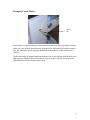
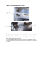
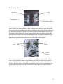
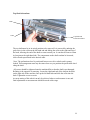
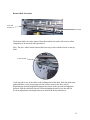
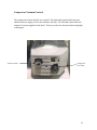
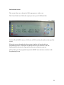
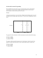
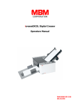
06-11-2007
CREASE MATIC
AUTO 50
Operators Manual
Auto50-Ops-v1.0
Contents
Contents .............................................................................................................................. 2
Introduction......................................................................................................................... 3
Machine Components ......................................................................................................... 4
Setting Side Lays ................................................................................................................ 5
Setting Outfeed Tray........................................................................................................... 7
Changing Crease Matrix ..................................................................................................... 8
Choke Adjustment and Rotating Cylinder.......................................................................... 9
Thin Gauge Paper Setting. ............................................................................................ 10
Heavy Gauge Paper....................................................................................................... 10
Feed Gate Adjustment....................................................................................................... 11
Horizontal Adjustment.................................................................................................. 11
Vertical Adjustment ...................................................................................................... 12
Perforation Wheels............................................................................................................ 13
Top Shaft Alterations.................................................................................................... 14
Bottom Shaft Alterations .............................................................................................. 15
Compressor/Vacuum Controls.......................................................................................... 16
Screen Sequence. .............................................................................................................. 17
Operator Run Screen..................................................................................................... 17
Job Selection Screen ..................................................................................................... 18
Programming Screen..................................................................................................... 19
Warning Lamps............................................................................................................. 20
Absolute and Incremental Programming ...................................................................... 21
2
Introduction
Crease Matic Auto 50
Designed and manufactured in the U.K., the new Crease Matic Auto 50 is a fully
programmable high speed card creaser. Documents are suction fed and creased at up to
7000 sheets per hour. It is possible to crease Digital and Litho printed card, removing
cracking that may occur at the folding stage.
The CM Auto 50 is capable of accommodating stock from CD-SRA2 (500x700mm), with
a capability to program a maximum of 29 creases per sheet anywhere along its length.
A maximum of 99 different jobs can be programmed and saved to the machines internal
memory, making the selection and recall of common jobs quick and easy.
Jobs may be programmed in either Absolute or Incremental measurements and image
shift adjustments can be made with one alteration.
The machine is supplied with rotary perforation that is adjustable across the width of the
document, and four widths of slide-out and turn crease matrix as standard.
3
Machine Components
Air flow
controls
Feed Gate
Backstop
Side Lays
Lay Squareness
Adjustment
Top Cover
Programming
Screen
Choke Control
Wheel
Slide out
Crease Matrix
Outfeed tray
Compressor/Vacuum unit
controls
When installing the machine the supplied power cable should be plugged into the
switched power socket on the machine and then to the power supply socket. Switch the
machine on and the control screen should initialize. The compressor/vacuum unit has a
separate on/off switch located under the Choke Control Wheel. This allows the unit to be
switched off when not in use.
4
Setting Side Lays
There are two side lays on the machine which sit at each side of the paper on the infeed
section. Their purpose is to guide the paper under the feed gate and into the feed rolls
accurately, to ensure a square crease is made across the document. They also supply air to
the underside of the paper stack, by way of thin slots, in order to make the paper “float”
before the bottom sheet is vacuum fed away under the feed gate.
On the CM Auto 50 there is also the capability to adjust the lays out of squareness to
accommodate for non square crease lines, although this adjustment is minimal.
Right Hand
Thumbscrew
Left Hand
Thumbscrews
Air Flow
Controls
Side Lays
Squareness
Adjustment
Location
Slots
Firstly, ensure that the squareness adjustment is set to its central position by aligning the
two marks on the machine bed.
The right hand side lay has four location positions. By removing the thumbscrews at the
feed gate end, the lay may be extracted from one slot and repositioned in another, using
the thumbscrew to secure it. This position must be selected with the paper size being fed
in mind, in order to keep the feed gate as central as possible to the paper centre line.
Once the right hand lay is in position, loosen the two thumbscrews at either end of the left
hand side lay and with a single sheet in the machine, push it across to the correct width of
document. The lays should not pinch the document and the paper must sit on top of the
protruding edge at the base of the lay. Secure the thumbscrews when in position.
5
Setting Side Lays cont.
Air Flow
Controls
Air Flow
Slots
Air flow to the slots is controlled using the thumbscrews running along the top edge of
each lay. By screwing them down all the way the flow of air will be stopped. This should
be done if the document does not cover the slots. Screwing them up will allow air to pass
through the slot. The thumbscrews are fitted with antivibration devices, to prevent the
settings from altering during normal operation. After placing the paper onto the machine,
the magnetic backstop should be placed behind the stack to prevent it from moving.
6
Setting Outfeed Tray
Thumbscrews
Magnetic
Side Lays
Bottom
Stop Plate
The outfeed tray has two thumbscrews , one on each side. By loosening the thumbscrews
the bottom stop plate may be extended to allow larger sheets to be collected without
damage.
The magnetic side plates may be positioned to keep fed documents stacked accurately.
The outfeed tray can be removed in order to adjust the lower perforation wheel shaft.
7
Changing Crease Matrix
Matrix
Bar
The machine is supplied with two crease matrix bars that have different widths of slot on
either side. One of these slots allows the operator to use replaceable self adhesive matrix
bars, the other three may be changed depending on the thickness of the material to be
creased.
The bar must only be changed while the machine is in its rest position with the knife at its
highest point. Withdraw the bar from the slot, turn or replace with the correct size slot,
and slid the bar into the machine until it stops.
8
Choke Adjustment and Rotating Cylinder
Choke Control
Wheel
Rotating
Cylinder
Feed Gate
The choke is used to control the amount of vacuum applied to the front edge of the paper
through the rotating cylinder holes.
The amount of vacuum needed is dependant on the type of paper being fed. Thin gauge
paper, 80gsm to 90gsm will tend to wrap around the cylinder easier than thick gauge
paper, and will need less vacuum to feed.
By rotating the choke control wheel clockwise, more area of slot inside the cylinder is
exposed through the holes and so more of the front edge of the document is sucked onto
the wheel.
9
Thin Gauge Paper Setting.
Rotate the choke adjustment knob anticlockwise until the slot inside the cylinder is tilted
towards the feed gate. This adjustment may be fine tuned during operation.
Feed Gate
Paper
Cylinder
Choke
Heavy Gauge Paper.
Rotate the choke clockwise until the slot is in an upright position.
Feed Gate
Paper
Cylinder
Choke
10
Feed Gate Adjustment
Horizontal
Adjustment
Vertical
Adjustment
The feed gate is set to allow only one document past at a time. This is achieved by
altering the gap and position of the bottom edge of the gate to the rotating cylinder. There
are two thumbscrew adjustments. One on top, to allow the vertical movement of the gate,
and one under the top cover, to allow horizontal movement. Adjustment of the gate
carried out along with adjustment of the choke.
Horizontal Adjustment
Firstly, set the choke to the correct position for the thickness of document about to be fed.
Then, using the smaller thumbscrew, align the front face of the feed gate to the left hand
edge of the choke slot, seen inside the rotating drum.
Front Face
11
Vertical Adjustment
The vertical adjustment is used to achieve the correct gap between drum and feed gate
dependant on paper thickness being fed.
Place a stack of paper onto the machine feed table. With the machine and compressor
turned on, adjust the vertical thumbscrew until only one document is taken from the base
of the stack at a time.
12
Perforation Wheels
Top Wheel
Spring
Control Wheels
Bottom Wheel
The perforation wheels are located under the top cover of the machine. The outfeed tray
may be lifted clear of the machine in order to gain access to the lower shaft. By altering
the position of the wheels along their shafts, perforations can be made at any point across
the documents width. You can use the perforation wheels without needing to crease the
documents. There are also feed wheels on these shafts, and it may be necessary to alter
their positions to achieve the correct perforation position. To perform perforations away
from the centre of the paper, the order of the feed wheels and perforation wheels on the
shaft must be changed to maintain drive across the width of the document.
Location
Holes
Sprung
Locator
Top Shaft
and Collar
The wheels may be raised or lowered using the sprung locator to the left end of the top
shaft. Two location holes allow easy positioning of the shaft in either the up or down
position. The shaft must be in its up position to make any alterations to the perforation
position. When lowering the top shaft, the perforation wheel must be pulled against the
spring until it is located, so that the wheels are in contact when the spring is released.
13
Top Shaft Alterations
Bush
Collar
Top Shaft and
Perforation Wheel
The top shaft must be in its raised position to be removed. It is removed by undoing the
grub screw in the collar on the left hand end and sliding the collar to the right and out of
the bush, allowing the end of the shaft to come towards you. It can then be removed from
its location on the right hand side. The components on the shaft can then be loosened,
slide off and repositioned in the desired order.
Note. The perforation wheel is positioned between two drive wheels and is sprung
loaded. This arrangement must stay the same wherever you position the perforation wheel
along the shaft.
All screws should be tightened onto the machined flat so that the shaft is not damaged.
Refitting is the opposite of removing. Locate the right hand end of the shaft in the bush
on the right side of the machine, line up the left hand side and slide the collar into the
bush. Tighten the screw to secure.
Accurate setting of this wheel can only be achieved when a test document is run, and
final adjustments to measurements should be made at this stage.
14
Bottom Shaft Alterations
Collar and
Grub Screw
Bottom Shaft
The bottom shaft can not be removed from the machine but can be slid across to allow
components to be removed and repositioned.
Note. The drive wheels on the bottom shaft must stay in line with the wheels on the top
shaft.
Collar and Gap
Undo the grub screw in the collar on the left hand end of the shaft. Slide the shaft to the
right until there is a big enough gap near the collar to remove the drive wheels.
Reposition the desired components opposite the wheels on the top shaft and tighten in
position. Slide the shaft back into the collar and tighten the grub screw onto the flat.
Accurate adjustments and alignment may be made with the top shaft down.
15
Compressor/Vacuum Controls
The compressor/vacuum unit has two controls. The right hand control wheel increases
and decreases the supply of air to the machines side lays. The left hand control alters the
amount of vacuum supplied to the choke. This may need to be decreased when using light
or thin paper.
Vacuum Control
Compressed
Air Control
16
Screen Sequence.
On switching on the machine the KAS logo will be displayed for a few seconds, this is to
allow the main processor to power up. When this has completed its procedure the first
screen will be displayed.
Operator Run Screen
The Operator Run Screen will be displayed under normal run conditions.
The screen shows us various pieces of information about the job being run at the time. It
consists of four lines, and is controlled by the six buttons to the right of the screen. These
buttons consist of UP, DOWN, LEFT, RIGHT, TICK and X.
Line 1 displays the speed that the machine is currently set to run at in the top left hand
corner. This may only be altered while the machine is at rest by pressing the UP and
DOWN arrows.
In the top right hand corner is the START prompt. To start the machine the green TICK
is pressed.
Line 2 consists of ABSOLUTE and INCREMENTAL measuring. The LEFT arrow is
used to switch between the two.
The RIGHT arrow is used to run a single sheet test. With the machine running, each time
the RIGHT arrow is pressed a test sheet will be sent through the machine. This allows the
operator to adjust the crease and perforation position before starting the main run.
Line 3 shows us the JOB number or program being run and the number of sheets that
have been completed using that job number.
Line 4 has the SETUP prompt. Pressing the red X button takes us to the job selection
screen.
17
Job Selection Screen
This screen allows us to choose the JOB or program we wish to run.
The Crease Matic Auto 50 has the capacity to store up to 99 different Jobs.
Use the UP and DOWN arrows to INCrease or DECrease the job number at the top of the
screen.
When the correct job number has been reached, and the job has already been
programmed, use the TICK button to confirm and save your selection. You will
automatically be taken to the Operator Run Screen to commence your run.
If the job has yet to be programmed, press the RIGHT arrow (Next) to continue to the
Programming Screen.
18
Programming Screen
This screen allows you to set up to 29 different positions of crease on each document.
Line 1 shows which crease line is being programmed and what its current value is in mm.
Line 2 shows the operator if they are working in Absolute or Incremental.
Line 3 shows which line of the current program is being worked on and what increments
are being used, 1mm or 0.1mm.
To switch between increments, press the X button. It is advised that whole mm are
programmed before tenths.
Line 4 has arrow functions, UP for Increasing the value, DOWN for Decreasing the
value, LEFT to go Back to the previous screen and RIGHT to advance to the Next crease.
When the last crease position has been programmed, press the RIGHT button and then
the TICK button to save the settings to memory.
The display will automatically return to the Operator Run Screen in order to commence
the job. The sheet counter will also be reset to zero.
Alterations to a previously programmed job are achieved by indexing through the
program until the required field is reached, changing the settings and saving the new
settings.
19
Warning Lamps
There are four lamps situated to the left hand side of the control screen. Under normal run
conditions they will be green. When an error occurs they will change to red.
Lamp1
Lamp 2
Lamp 3
Lamp 4
Red Lamps
Lamp 1- Programming screen is in engineers mode
Lamp 2- Page overlength. Two or more sheets have been fed.
Check feed gate, choke and vacuum settings.
Lamp 3- Page underlength
Lamp 4- Knife jam. This is caused when the knife is jammed in the down position
More than one sheet has been fed or the incorrect crease matrix is fitted.
The paper must be removed. It may be necessary to remove the crease matrix.
Check feed gate settings and crease matrix size.
20
Absolute and Incremental Programming
The main difference between the two types of programming system is that Absolute
measurements are taken from the leading edge of the document, and Incremental
measurements are taken from the previous crease line.
Example.
A document requires three creases, the first is 100mm from the leading edge, the second
is 150mm from the leading edge and the third is 175mm from the leading edge as shown
below.
1st
Front Edge
100mm
2
3rd
50mm
25mm
nd
To program this job in Absolute, all of the measurements are taken from the front edge,
1st crease at 100mm
2nd crease at 150mm
3rd crease at 175mm
To program with Incremental measurements, the first distance is taken from the front
edge, the second is taken from the first crease, and the third from the second crease.
1st crease at 100mm
2nd crease at 50mm
3rd crease at 25mm
21