1
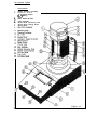
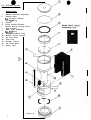
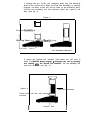
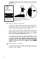
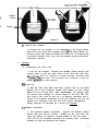
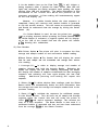
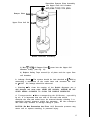
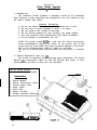
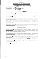
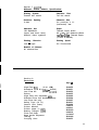
Instruction Manual
for the
Gilian”
Primary Standard Airflow Calibrator
with Interchangeable Flow Cell Assemblies
Flow Cell Assembly Ranges
Low : 1 to 250 cc/min.
Standard : 20 cc/min. to 6 LPM
High : 2 to 30 LPM
On-Site Instruments
l-8OO-7-On-Site
(l-800-766-7483)
689 North James Road - Columbus, Ohio 43219
Prologue
This Instruction Manual describes the basic principles, installation,
operation/controls and maintenance for the Cilibrator, Primary Standard
Airflow Calibrator manufactured by Cilian Instrument Corp.
Table of Contents
The Gil ibrator
Page #
Section #
1
Introduct
ion
2
2
General
Description
2-6
3
Theory
4
Operating
Procedures
Initial Set-up & O p e r a t i o n
8-12
5
Storage
13-17
6
The Printer Module
Introduction E
General
Description
Theory of Operation
Operation
Procedures
Storage and Maintenance
7
of
E
Operation
Maintenance
7
18
18-19
19
19-21
21
Spec if icat ions The Gil ibrator
The Printer Module
22
23
8
Cilibrator Parts List
23
9
Warranty E Service Policy
24
1
Section 1
Introductih
The Gilibrator is a high accuracy, electronic bubble flowmeter that
provides instantaneous air flow readings and a cumulative averaging of
The Gilibrator system provides a large dynamic range
multiple samples.
through the use of 3 interchangeable flow cell assemblies.
A delete
f u n c t i o n , o n t h e C o n t r o l U n i t , subtracts eroneous readings to insure
a c c u r a t e d a t a . The Control unit also supports a hard copy print out through
the use of a printer accessory-.
Section 2
General Description
(See
fig.
la)
The Gilibrator is comprised of the following basic components: Flow
Cell Assembly, Control Unit (base), Battery Charger and Soap Solution. Different sized inter-changeable Flow Cell Assemblies are available for use as
follows:
Low Flow
: 1 to 250 cc/min.
S t a n d a r d F l o w : 2 0 cclmin t o 6 L P M
High Flow
: 2 to 30 LPM
In addition to the basic components, an optional Printer Module is
available.
The printer provides a hard copy record of calibration data,
however,
identical data is displayed on the LCD of the Cilibrator Control
Unit during calibration.
1. Flow Cell Assembly (See fig. lb)
The Flow Cell Assembly consists of a Bubble Generator and Sensor
Block. Each Bubble Generator is sized to produce a bubble film stretched
across the diameter of the flow cell tube which is carried by airflow from
the bottom to top of the tube. A s t h e b u b b l e t r a v e r s e s p a s t t w o i n f r a r e d
sensors, each sensor transmits a signal to the Control Unit (base) indicat i n g t h e p a s s a g e o f t h e f i l m . The Flow Cell Assembly incorporates a manual
bubble initiation push button which starts the film on its travel up the
tube.
A.
Bubble Generator
1) Flow Ranges
Low Flow
: 1 t o 2 5 0 cclmin.
S t a n d a r d F l o w : 2 0 cc/min t o 6 L P M I
High Flow
: 2 to 30 LPM
2) Pulsation Damper (2) - a built-in damper smoothes out any
pulsation’ within the airflow and reduces occilation of the bubble
film assuring maximum accuracy.
3) Bu bble Initiate Button (22) - T h i s p u s h b u t t o n
Generator Ring (21) into the soap solution
releasing the button, the ring lifts out of the
a film bubble is generated across the opening
(241.
2
lowers the Bubble
reservoir.
Upon
soap solution and
of the flow tube
4 ) B u b b l e B r e a k e r ( 4 ) - The Bubble Breaker is a secondary chamber
in the upper chamber which provides the soap film a rapid expansion path which is instrumental in breaking the bubble. ‘This
prevents excessive wall wetting by the soap film and allows it to
flow back into the cell.
5) Storage Tubing (25) - T h i s a n t i - s p i l l t u b i n g c o n n e c t s u p p e r a n d
lower cell chambers and prevents the soap solution from evaporating which may cause the solution concentration to change.’
CAUTION: If transporting by plane, be sure to disconnect this hosing from
upper or lower Flow Cell Chamber Bosses (23 & 26) to prevent pressurization
and possible rupture within the Bubble Generator.
8.
Sensor Block (8)
S u r r o u n d i n g t h e f l o w t u b e (24),and s e c u r e d b e t w e e n t h e u p p e r a n d
lower chamber of the bubble generator, is the Sensor Block (8).
The blockincorporates lower and upper sensors for time start and
time stop. Thesensors consist of an infrared emitter and detector
p a i r s w h o s e s e n s i t i v i t y a n d a c c u r a c y i s c o n t r o l l e d b y a “columnating slot”.
This block is secured to the Bubble Generator
Assembly (1) by means of two Locking Screws ((7) and allows easy
removal to facilitate cleaning.
1) Electrical Interface - The Electrical Interface provides power
to the sensing system as well as transmits timing information to
the Control Unit.
2. The Control Unit (base) (See fig. la)
The Control Unit (14) contains a crystal controlled timing system,
a micro processor control system, and an LCD readout for displaying
flow and messages.
The Control Unit also contains switches for Reset
(17), D e l e t e ( 1 6 ) a n d A u t o - A v e r a g i n g ( 1 5 ) f u n c t i o n s a s w e l l a s a n
Printer Jack (18) interface port for direct connection to a hard copy
printer. LED indicators are provided to note Charging (11) and Run
calibration (20) operation.
a ) Power ( 1 2 ) - s w i t c h t u r n s t h e C o n t r o l U n i t s p o w e r o n a n d o f f .
b) Charge Indicator LED
into the Charging Jack
c) Printer Jack
d) Reset
themicro
(11)
- lights
when
the
charger
is
plugged
(18) - provides interface for auxillary printer.
(17) - p u s h b u t t o n d e l e t e s a l l c u r r e n t i n f o r m a t i o n
processor in order to initiate a new sequence.
for
e) Delete (16) - push button automatically deletes false information from the average and will reset the average and sample number
When a printer is in line, this will
to the previous reading.
indicate a minus symbol and the average will return to the
previous value.
3
f) Average (15) - p u s h b u t t o n w h e n p u s h e d a n d h e l d w i l l d i s p l a y
the average of the previous sequence of readings. When released
will display the last actual reading and when re-pushed and held,
w i l l s h o w t h e numbe,r o f s a m p l e s i n t h e s e q u e n c e w i t h d i s p l a y
information (S=sample
#). Releasing the button will automatically bring the display back to the last reading.
g) Sequence Run Indicator LED (20) - indicates bubble sequence by
lighting as the bubble passes between the two sensors. The LCD
(19) will be blank.
The Run signal will also light when turning
on the Control Unit and will extinguish after unit has finished
it’s initial sequence check.
h) Low Battery - w i l l i n d i c a t e o n t h e L C D d i s p l a y ( 1 9 ) i f i n s u f f i cient battery voltage is available to operate the unit properly. Since power for all Control Unit functions is derived from the
r e c h a r g e a b l e ‘NiCad b a t t e r y , t h e b a t t e r i e s m u s t b e f u l l y c h a r g e d
f o r p r o p e r o p e r a t i o n . A “Low B a t t e r y ” i n d i c a t i o n w i l l a l s o a p p e a r
initially when turning the Control Unit ON as a sequence check of
the unit’s electronics.
i) C a b l e A s s e m b l y (5) - m a t e s w i t h t h e C o n n e c t i n g J a c k ( 6 ) i n t h e
back of the Sensor Block. It provides power for the sensing
system,
information regarding cell size , and control of the
timing information to the micro processor.
j) T i m i n g S y s t e m - T h e q u a r t z c o n t r o l l e d t i m i n g ‘ s y s t e m c o n t r o l s
i n f r a - r e d s e n s o r a c t i v a t i o n t o a s s u r e m a x i m u m c a l c u l a t i o n accuraCY.
k) Micro Processor - controls the timing and mathematical data
processing to provide optimum flow measurement characteristics.
This programmable micro processor can be upgraded as new programs
become
available.
3.
Battery
Charger
Standard wall operated 120V charger to charge Gilibrator Control
U n i t f o r 1 4 h o u r s p r i o r t o o p e r a t i o n . The Charging LED on the Control
U n i t w i l l b e i l l u m i n a t e d w h i l e ,charging i s i n p r o g r e s s .
4. Soap Solution
This specially compounded low residue soap is specifically
designed to provide high film strength and compatibility with the
materials used within the Flow Cell Assembly.
The Gilibrator System
The Gilibrator
Nomenclature
1.
2.
3.
::
6.
7.
6.
9.
Bubble Generator Assembly
Damper Plate
2a. Pulsation Damper
2b. “0” Ring
Spacer
Plate, Bubble Breaker
Cable Assembly
Sensor Block Connecting Jack
Sensor Block Locking Screw
Sensor Block
10.
11.
12.
13.
14.
15.
16.
17.
16.
19.
20.
21.
22.
23.
24.
25.
26.
Figure
la
The Gilibrator System
The Flow Cell Assembly
Nomenclature
1.
2.
3.
4.
7.
a.
9.
21.
22.
23.
24.
25.
26.
27.
I
I
Bubble Generator Assembly
Damper Plate
2a. P u l s a t i o n D a m p e r
2 b . “0” R i n g
Spacer
Plate, Bubble Breaker
Sensor Block Locking Screw
Sensor Block
Base Plate Assembly
9a. “0” R i n g
Bubble Generator Ring
Bubble Initiate Button
Air Inlet Boss
Flow Tube
Storage Tubing
Air Outlet Boss
Safety Tape
a---
Figure lb
6
w
Section 3
Theory
of
Operation
1.
Primary Airflow Standard
To be a primary standard, all values must be absolute and measured as
absolute.
A primary standard airflow measurement is a volume divided by a
time interval as performed by the Control Unit of the Gilibrator.
The
volume, V, is measured volume of space between two infrared sensors. The
time is that interval needed for a soap film bubble to traverse between the
two sensors which bound the volume. T h e r e f o r e , V/t, t h e v o l u m e p e r u n i t o f
time, becomes the airflow and is prime because all measurements are basic...
volume and time.
In today’s technology, time is measured by an electronic
clock whose accuracy exceeds that of volume measurements by orders of
magnitude, hence, the control accuracy volume resides solely with volume
measurements.
2. Bubble Generation and measurement
a) The Gilibrator consists of two elements, the Flow Cell Assembly and
the Control Unit (base).
T h e f u n c t i o n o f t h e F l o w C e l l A s s e m b l y -is to
generate a clean consistent bubble which traverses up the flow tube. Measurement of the traverse time is done by infrared sensor pairs which are
m o u n t e d a t t h e b o t t o m a n d t h e t o p o f t h e S e n s o r B l o c k . The volume bound by
these sensors is specifically adjusted to a volume standard by allowing the
upper sensor blocks to move in unison so as to enable this calibration to be
set accurately to a primary volume standard,
A second function of the
sensor block provides the interfacing code to define the cell volume as well
as sensitivity adjustments for the optical sensor systems.
b) A s t h e b u b b l e t r a v e r s e s b e t w e e n t h e s a n s o r s , f i r s t o n e a n d t h e n t h e
second,
sensors are tripped thereby providing the time for the bubble
This timing information is sent to the micro processor of the
traverse.
control base which in turn provides the crystal control time base for the
T h e t i m i n g i n f o r m a t i o n a l o n g w i t h t h e volu,me i n f o r m a t i o n a r e t h e n
system.
sent to the micro processor which in turn does the necessary mathematical
calculations which allow the flow to be displayed directly on the LCD
readout.
In order to insure the highest accuracy possible, a Delete and
Average function are provided on the Control Unit. The Delete allows for
subtracting out an obvious malformed bubble and the average allows the user
to obtain average information without pencil or paper. A printer interface
allows connection of a Printer Module so that hard copy can be produced.
Section 4
Operating
Procedures
1.
Initial
Set-up
This covers all steps necessary to bring the Gilibrator into
This includes charging, cell mounting, installing
operating
status.
soap solution, connecting the printer (optional) and connecting the
sampling source.
A)
Charging the Gilibrator
1. Prior to operation, plug the 120V charger into the wall and
connect to the Charging Jack (13) on the right side of the Control
Unit. The unit’s Charging LED (11) will light indicating that the
unit is charging properly. Allow the battery system to charge for
14 hours prior to operation.
B) M o u n t i n g t h e F l o w C e l l A s s e m b l y ( S e e f i g . 2 )
1. Select the Flow Cell Assembly to cover the flow range
required.
2. The bottom of the Flow Cell Assembly employs a quick mount
feature.
The base of the Flow Cell Assembly is positioned onto
the mounting plate (10) of the Control Unit (14).
Figure 2
M O ‘unting
late
Cell Assembly
(bottom)
Control
Unit
J
a
3. Engage the pin of the cell assembly base into the mounting
plate of the Control Unit. When the Flow Cell Assembly is properly
engaged, the base of the cell will be flush to the mounting plate
and the cell assembly will face towards either the right or left
side. (See fig. 3)
Figure 3
I
I
I
I
I
I
F l o w C e l l Assembly-
‘Mounti
Control
I
Unit/
Cell Assembly Mounted
4 . G r a s p t h e b o t t o m c e l l c h a m b e r and r o t a t e t h e c e l l u n t i l i t
clicks in. CAUTION: Always engage E disengage the cell by grasping
and rotating 09 the bottom cell chamber. The cell assembly will
now face forward. (see Fig. 4)
Figure 4
Flow Cell Assembly
Firmly twist cell into the locking
position
Control
Unit
5 . Insert t h e C o n t r o l U n i t ’ s C a b l e A s s e m b l y ( 5 ) i n t o t h e S e n s o r
Block Connecting Jack (6) located on the back of the Sensor Block
(8). ( S e e f i g . 5 )
Figure 5
0
. . . . .
. . . .
Sensor Block
Connecting Jack
Control
Unit
Interface Plug
Cl
Adding
Connecting the Control Unit’s
Interface Plug to the Sensor Block’s
Connecting Jack.
the
Gilibrator
Soap
Solution
1. Remove the Storage Tubing (25) from the upper Outlet Boss 26)
of the upper cell. Fill the dispenser bottle provided with
Cilibrator soap solution. Using the rubber Storage Tubing as a
funnel, slowly add soap solution from the dispenser.
2. The amount of soap needed is determined by depressing the
Bubble Initiate Button (22) and holding it down in the lower
position. Continue to add enough soap solution until the angled
edge at the bottom of the Bubble Generator Ring (21) is immersed
in the solution. Do Not Overfill! (See fig. 6)
3. After filling is completed, the rubber Storage Tubing (25) may
be removed completely.
Recap the soap dispenser bottle for later
u s e . N O T E : If the Flow Cell Assembly is not going to be used for
a prolonged period of time, reinstall the rubber Storage Tubing
between the inlet and outlet bosses (23 t 26). This will p&vent
evaporation from occurring which may cause the solution’s concentrations to alter.
D)
Printer
Connection
(if
applicable)
1. Connect printer cable to Printer Jack connector (18) on the
left side of the Control Unit. Be sure to properly match up
connectors before engaging.
10
Bubble
Initiate
Bubble
Gel
Solution Res
E) C o n n e c t
the
Sampler
1. Connect the air sampler to be calibrated to the Upper Outlet
B o s s ( 2 6 ) o f t h e F l o w C e l l A s s e m b l y w i t h l/4@’ ID tubing. NOTE: An
auxillary liquid trap between sampler and flow cell is recommended
to prevent moisture carry over into the sampler during continuous
calibration periods.
2
.
Operation
A)
Conditioning
the
Flow
Tube
1. Turn on the sampler.
Depress the Bubble Initiate Button (22)
several times to wet the inner walls of the flow tube (24). You
will not be able to initiate a timing bubble without first
“Priming”the f l o w t u b e . T h e o p e r a t o r w i l l d e v e l o p a f e e l f o r
b u b b l e generat i o n w i t h p r a c t i c e .
B) P o w e r U p
2. After the Flow Tube walls have been “primed”, turn on the Power
Switch (12) of the Cilibrator Control Unit (base) and the Printer
M o d u l e i f o n e i s b e i n g u s e d . Wait approximately 10 seconds while
the system runs through it’s check sequence. The Run LED (20)
will light at this time as well as a Lo Battery indication and a
series of five dashes displayed on the LCD Readout (19). Do not
operate the Cilibrator until the Run LED signal extinguishes.
Ready operation is indicated by a series of 4 dashes.
C)
Bubble
Generation
depress the Bubble Initiate
1. For optimum bubble generation,
Button (22) and hold to initiate 1 bubble up the flow tube. Release the button to initiate a second bubble up the flow tube.
This will be the standard procedure to making clean, consistent
bubbles at High and Medium flow ranges.
11
2 . A s t h e b u b b l e r i s e s u p t h e F l o w T u b e (24). i t w i l l i n i t i a t e a
timing sequence when it passes the lower sensor (Run LED will
light) and culminate the timing sequence upon passing the upper
sensors (Run LED will extinguish). The timing information is then
transmitted to the control unit which will perform all the
necessary calculation. A flow reading will instantaneously appear
on the LCD display (19).
However,
if a bubble breaks before the time sequence is
completed, timing will continue until another bubble is generated
to trip the second sensors. This will cause an erroneous reading
and should be subtracted from the average by hitting the Delete
Button (16).
If a Printer Module is used, be sure
Led i t ’ s p r i n t i n g s e q u e n c e b e f o r e p r e s s i n g
the Delete Button is activated, a negative
ed on the LCD of the Control Unit and
a’line
showing this subtraction.
t h e p r i n t e r h a s complethe Delete Button. When
symbol will be displaythe printer will initiate
D) Flow Readout
With Printer Option - T h e p r i n t e r w i l l p r i n t i n s e q u e n c e t h e f l o w ,
average and sample number of each successive bubble reading.
Without Printer Option - T h e C o n t r o l U n i t w i l l d i s p l a y t h e a c t u a l
flow for each sample and will accumulate and average each successive reading.
1 . A v e r a g e ( 1 5 ) - In order to display average and number of
samples, depress and hold the Average Button.
Releasing the
button will display the last flow reading. Repressing the button
will display the number of samples accumulated for that averaging
sequence and releasing will once again display the last flow
reading.
Additional pressing and holding will repeat this
sequence.
2. Delete (16) - To delete obvious false readings, push the Delete
Button which will automatically delete the false information from
the average and reset the average and sample number back to the
previous reading.
3. Reset (17) - To reinitiate the sequence for additional pumps,
h i t t h e R e s e t B u t t o n . This will zero out all sample and average
registers within the Control Unit and will cause the printer to
i n d e x oneline
and reprint sequence headings. This denotes the
start of a new sequence.
The Reset Button is also used if a
malformed bubble is generated and has not been been subtracted
f r o m t h e a v e r a g e byuse o f t h e D e l e t e F u n c t i o n .
12
Section 5
Storage t Maintenance
1.
Storage
A. Take Down
Turn OFF the Control
[if applicable).
Unit,
the
sampler
and
the
Printer
Module
B. For Daily Use
If Cilibrator
is to be used daily, it is recommended that the air
sampler be removed and the Storage Tubing be replaced between the upper
Plug in the Charger and connect into the
and lower cell chambers.
Control Unit Charging Jack (13).
Recharge overnight for next day
usage.
C.
Long Term Storage
If the Cilibrator is not to be used for long periods of time, the
following steps should be taken to keep the unit in proper working
order.
1. Disconnect the Cable Assembly
on t h e F l o w C e l l A s s e m b l y .
from
the
back
of
the
Sensor
Block
2. Remove the Flow Cell Assembly from the Control Unit (base).
Remove the Cell from the base in the reverse order in which it was
mounted.
3. Pour soap solution out of the Bubble Generator through the
L o w e r I n l e t B o s s (23) B y h o l d i n g B u b b l e G e n e r a t o r h o r i z o n t a l l y a n d
with the inlet boss facing down, tilt at a 45 degree angle. Continue until all of soap solution has poured out. (See fig. 7)
Figure 7
13
4. Flushing the Bubble Generator Clean - There are 2 methods in
which to cleanse the Bubble Generator.
a. The unit may be flushed clean by connecting Storage Tubing
to the Upper Outlet Boss and continuously running water
through the generator until water runs clear. Maintain a
horizontal position with cell bosses facing down and flush
Then remove tubing and rock the
for 15 - 30 seconds.
cell in a see-saw fashion to empty out all excess water.
Replace Seal Tubing between the Upper and Lower Cell bosses.
(See fig. 8)
Flow Cell Assembly
1
1 1 water clears. 1 1
Figure 8
I~FIOW
I
Cell
Assembly;
Rock the Flow Cell Assembly
in a see saw fashion.
or (see Figure 9)
b. Remove the Sensor Block Assembly by loosening the 2
holding screwsand sliding the block out from between the
Upper & lower cell chambers. Remove Safety Tape. Using a
small flat blade screw driver, lift off the Damper Plate (2)
using the notch between the upper chamber and the lid.
Remove the Spacer (3) and then the Bubble Breaker Plate (4).
This gives completeaccess to the interior of the Flow Cell
Tube. Continue to run clear water through the cell until
Rock cell to empty out all excess water.
water runs clear.
Replace the Bubble Breaker Plate (4) and center the Air
Outlet Boss (26) with the plates largest hole. Next insert
the spacer. To replace the Damper Plate assembly, moisten the
O-ring (2b) w i t h s o a p s o l u t i o n a n d t h e n p r e s s t h e D a m p e r
Plate into the top of the Upper Cell Chamber.Use fingers and
firmly sqeeze p l a t e i n t o u p p e r f l o w c e l l c h a m b e r .
14
Figure 9
g-&J,
Flush
1 -Doer F l o w C e l l Chlamber
1
Screws
Do Not exert your body weight
on the Bubble Generator to
press plate into place. Excessive weight on the flow cell
may result in breakage.
Replace the Seal Tubing between
the Upper and Lower cell bosses
for storage.
r
Damper Plate
Upper Flow Cell
#sembly
1
Reposit ior! D a m p e r P l a t e A s s e m b l y
into Upper F l o w C e l l C h a m b e r
and press firmly into place.
hamber
Bubble Generator Assembly
L
15
2. Maintenance
The Cilibrator is designed so that little maintenance is required. The
area which may need replacement is the Damper Diaphragm assembly. If the
diaphragm becomes ruptured or worn please use the following procedure for
its replacement.
a. Removing and Replacing Damper Plate Diaphragm
First, remove flexible Safety Tape (27) from around the lip of the
1) Using a small flat blade screwdriver, remove
Damper Plate assembly.
the Damper Plate (2) from the Upper Cell Chamber using the notch
provided.
R e m o v e t h e l a r g e O - r i n g (2b) a n d t h e P u l s a t i o n D a m p e r
d i a p h r a g m (2aI. ( S e e f i g . 1 0 )
CA\
Damper Plate Assembly
Figure 11
[A
!r F l o w C e l l C h a m b e r
Insert a Fiathead Screwdriver
between the Damper Plate Assembly
the Iip of the Upper Flow Cell
a m b e r . Gently pry apart the two
twisting the screwdriver.
f3
Q
0
b-4
F
i
g
u
r
e
1
0
Damper Plate
Bubble Generator Assembly
2) To replace, center new diaphragm over Damper Plate aperture and
roll O-ring over diaphragm and into the O-ring groove. If
wrinkles occur, repeat the procedure to achieve a smooth placement. (See fig. 11)
16
Reposition Damper Plate Assembly
into Upper Flow Cell Chamber
D a m p e r P l a t e Asss
bly-
Upper Flow Cell Ch
lber -
Figure 12
Bubble Generator Assembly
.
3) Wet 1@088-ring
of Damper Plate
Chamber firmly. (see Fig. 12)
4) Replace Safety
cell chamber.
Tape
around
& press into the Upper Cell
lip
of
plate
and
the
upper
flow
b . L e a k a g e C h e c k - T h e s y s t e m s h o u l d b e l e a k c h e c k e d a t 6” H20 by
connecting a manometer to the outlet boss and evacuate the inlet
No leakage should be observed.
t o 6” H 2 0 .
c. Cleaning - To clean the exterior
mild detergent and warm water. NEVER
OTHER HARSH CLEANERS TO CLEAN
of the Bubble Generator use a
USE ALCOHOL, ACETONE OR ANY
THE BUBBLE GENERATOR.
d. Transportation - When transporting the Gilibrator, especially
by air, it is important that one side of the seal tube which
connects the inlet and outlet boss, be removed thereby allowing f o r
equalizing internal pressure within the generator.
Do Not transport
unit with soap solution or storage tubing in place.
CAUTION: D o N o t P r e s s u r i z e t h e F l o w C e l l ! E x c e s s i v e p r e s s u r e m a y
cause cell to rupture resulting in personal injury.
17
Printer
Section 6
Module
Operation
Part # C-800274
1. Introduct ion
The Cilibrator Printer provides a hardcopy record of all calibration
data, identical to data calculated and displayed on the LCD readout of the
Gil ibrator Control Unit (base).
a.
b.
c.
d.
e.
f.
Handling Precautions
Do not use where the temperature is extremely hot or cold.
Do not leave in direct sunlight or where it is dusty.
Do not operate near liquids or beverage.
Do not operate without the heat sensitive roll paper loaded.
Use only specified Cilian Replacement Roll Paper (A-400681).
Do not attempt to disassemble the unit.
NOTE: The printer should 0% b e u s e d w i t h t h e C i l i a n I n t e r c o n n e c t
Cable providedwhich supplies the *power for the printer. Use of this
printer with any other cable may cause permanent damage to the printer
and to the equipment from which the cable is connected.
The use of a non-shielded interface cable with the printer is prohibited.
2.
G e n e r a l D e s c r i p t i o n ( S e e f i g . 13)
The Printer is comprised of the following basic components: The Printer
M o d u l e (l), I n t e r c o n n e c t C a b l e ( 2 ) a n d t h e T h e r m a l R o l l P a p e r . A b r i e f
description is provided of their use and operation.
The Gil ibrator System
The Printer Module Assembly
Nomenclature
1. Printer Module
2. Printer Interconnect Cable
3. Thermal Paper Cover
4. Paper Cutter
5. Paper Feed
6. Power (On-Off)
7. Parallel Interface Connect0
18
a) Printer Module
1 .Power (6) - T h i s s w i t c h a c t i v a t e s o p e r a t i o n o f t h e p r i n t e r f r o m
the Control Unit’s power source.
The printer will initially print
a heading line upon activation.
2.Paper F e e d ( 5 ) - T h i s s w i t c h i s u s e d t o f e e d t h e T h e r m a l P a p e r
continuously.
P r e s s i t l i g h t l y . N o t e : Use the Paper Feed switch
to feed out the paper.
If paper is pulled out by hand, always
feed it one line with the Paper Feed Switch before starting
printing.
3.Paper C u t t e r ( 4 ) - T h i s i s u s e d t o t e a r o f t h e p a p e r . T e a r o f f
by pulling it in the arrow direction only.
b) Thermal Paper printer head.
A specially treated paper which is activated by the
.c) Interconnect Cable (2) - T h e i n t e r c o n n e c t c a b l e p r o v i d e s e l e c t r i c a l
connection between the printer (1) and the Gilibrator Control Unit
The printer operates from the same power source as the control
(14).
unit.
3.
Theory
of Operation
The Printer Module is powered and interfaced to the Control Unit
pf t h e C i l i b r a t o r b y m e a n s o f a n I n t e r c o n n e c t C a b l e .
During a test
series, the Control Unit transfers the sum of calculations of a given
calibration bubble and provides the flow rate, the sample number and an
average of the successive flow rates determined in that calibration
series.
The buttons on the Control Unit are used in conjunction with the
Printer module during calculation.
Delete, Auto Average and Reset
buttons are provided to subtract false readings and to initiate new
calibration sequences.
Calculations are automatically provided by the Control Unit and
transferred to the printer for a hardcopy readout. This is printed
onto a thermal sensitive roll paper which advances a single line after
printing out each successive reading. These hard copy calculations are
retained for calibration records.
4.
Operation Procedures
a) Initial set-up
1 .Connect
ing the Printer
a) While the Gilibrator Control Unit is in the OFF mode,
connect the large end of the Interconnect Cable (2) to the
Printer Modules Parrallel Interface Connector and snap
holding clips in place.
Connect the smaller end to the
Control Unit’s Printer connect port. Power is supplied to the
printer from the Control Unit’s battery system.
2.
Turn
ON
the
Control
Unit
and
the
Printer
Module.
19
1
3.
Remove the heat sensitive roll paper cover.
Installing the
Thermal Paper (See fig. 14)
a . SI i d e b a c k a n d r e m o v e
the Thermal Paper Cover
(3) from the printer
section. (see Fig. 14)
b . U s e t h e s p e c i a l Cilian
heat sensitive roll paper
(A-400681).
2) Cut the end of the heat sensitive paper a
shown below.
n n
c.
Cut
the
end
of
the
paper in a half circle or
triangular shape.
d. While inserting the end
of the paper, press the
Paper Feed Switch (5)
until the paper is fed
Replace
protective
out.
paper cover. (see Fig. 15)
Figure 14
(3) While inserting the end of the tieat sensitive
roll paper in the direction of the arrow, press
and hold the paper feed switch until the paper
is fed out. Since the outside of the heat rensitive roll paper is coated with a heat sensitive
agent,‘pay careful attention to the front and
back of the paper.
Figure 15
b)
Operation
1. Start Sequence
a. Turn the Control Unit ON.
out an identification heading
test. The program version is
t ion line for future reference.
The Printer Module will print
for the current calibration
i n d i c a t e d a f t e r t h e identificaSee sample below.
b. Initiate a bubble up the Flow Tube:and observe the reading
on the Control unit and also on the Printer Module.
The
Printer will print in sequence the flow, average and sample
number after each successive reading.
NOTE : If you do not need a hard copy printout from the Printer Module, turn
it OFF.
This will preserve the battery life of the Gilibrator as the
printer is powered by same.
2 . T h e A v e r a g e , R e s e t a n d D e l e t e b u t t o n s o n t h e C o n t r o l U n i t are
used in conjunction with the printer during calibration. They are
as follows:
a) Average - In order to display average and number of samples,
depress and hold average button.
Releasing the button will
display the last reading.
Repressing will display the number of
samples accumulated for that averaging sequence.
Releasing the
button will once again display the last flow reading. Additional
pressing and holding will repeat this sequence.
b. Reset - To reinitiate the sequence for additional pumps,hit
the Reset Button. T h i s w i l l z e r o o u t s a m p l e a n d a v e r a g e r e g i s ters within the Control Unit and will cause the printer to index
one line and reprint headings. This denotes the start of a new
sequence.
The Reset Button may also be used if a malformed bubble
is generated and has not been been subtracted from the average by
use of the Delete Function.
c.Delete
- To delete obvious false readings, press the Delete
Button and subtract the false reading from the average. This
resets the average and sample number back to the previous reading.
5. Storage E Maintenance
a) Storage (Daily Take Down)
1. Turn the Power of the Printer Module OFF. All data stored in
the printer cannot be reviewed once this is done.
2. Turn off the Power of the Control Unit.
3. Turn off the Power of the Sampler being calibrated.
b) Storage (Long Term) - I f t h e P r i n t e r M o d u l e i s n o t t o b e u s e d f o r
long periods of time, the following steps should be taken to keep the
unit in proper working order.
Disconnect the interconnect cable from the Control Unit and
1.
from the Printer Module.
2. Store in original packaging or carrying case.
c) Cleaning - Use a damp cloth with warm
ACETONE or any other harsh cleaners.
water.
Never
use
ALCOHOL,
Specifications
Flow CelC
Section 7
for the Gilibrator
System
Assembly Ranges Available 1
High Flow Cell
2 - 30 LPM
S t a n d a r d F l o w C e l l 2 0 cclmin. - 6 L P M
Low Flow Cell
1 - 2 5 0 cc/min.
Operational
Features
D i r e c t F l o w R e a d i n g s - The easy to read LCD read-out on the Control Unit
(base) instantly displays flow readings.
Auto Averaging - A switch on the Control Unit provides Auto-Averaging of the
successive flow readings.
Flow Delete Function - A Flow Delete switch allows the user to delete
erroneous flow readings from the Auto-Averaging function. For example, if a
double bubble or other obvious malfunction is observed, that reading can be
subtracted from the auto-average and will automatically reset the average to
it’s previous value.
Programmable Update - The micro-processor electronic design allows programmable updates to assure a long useful service life.
Mechanical
Features
Pulsation Damper - The pulsation damper removes pulsation from the flow
source for higher accuracy sampling as well as eliminating pulsations back
into the flow source during bubble generation.
i
Ring Bubble Generator - The Ring Bubble Generator lifts an even soap film
from the soap reservoir and provides consistent bubble generation.
.
Bubble Breaker - The Bubble Breaker design allows the soap film to be drawn
away form the end of the flow tube before bursting. This improves flow
m e a s u r e m e n t a c c u r a c y b y m i n i m i z i n g f i l m r e s i d u e Svithin t h e f l o w t u b e .
Programmable Update - The electronics
assure a long, useful service life.
Accuracy
22
- Better than 0.5%
design
allows
programmable
updates
to
S e c t i o n 7 (cont’d)
Gilibrator Printer Module
Printing
Thermal
Specifications
System
dot matrix
Character
2 dots
Spacing
Character
Font
7x5 dot matrix
Character Size
2.4 (vertical) x 1.1
(horizontal) mm
Character Set
159 Alphabetic
(upper and lower case),
numeric, Kana, symbols
Paper
Thermal Paper width
80 + lmm, roll diameter 40mm
reo;der Cilian T h e r m a l P a p e r
(3 rolls A-400681)
Printing
Direction
Left - right
Printing Speed
0.6 line/second
Number of Columns
40 columns/line
Section 8
Parts List
(2-30 LPM)
H i g h F l o w Kit(
S t a n d a r d F l o w K i t (2Occ - 6 L P M )
( l - 2 5 0 cclmin)
Low Flow Kit
Deluxe
H i g h F l o w C e l l A s s e m b l y only
Standard Flow Cell Assembly ‘only
Low Flow Cell only,
Safety Tape (10 ft.)
Control Unit (base)
Printer Module
Printer paper (3 rolls)
B a t t e r y C h a r g e r (120~)
Flow Cell Soap
Soap bottle dispenser
Tubing
Carrying Case
Part #
D-800270
D-800271
D-800272
D-800275
D-800265
D-800266
D-800267
B-800331
D-800268
C-800274
A-400681
B-400674
A-400450
A-400667
B-800269
D-800273
23
Section 9
Warranty
The Seller warrants to the Purchaser that any equipment manufactured by
it and bearing its nameplate to be free from defects in material or workmanIf, at any time
ship, under proper and normal use and service as follows:
within 90 days from the date of sale, the Purchaser notifies the Seller that
in his opinion the equipment is defective, and returns the equipment to the
Seller’s originating factory prepaid, and the Seller’s inspection finds the
equipment to be defective in material or workmanship, the Seller will
promptly correct it by either, at its option, repairing any defective part
or material or replacing it free of charge and returned shipped lowest cost
transportation
prepaid
(if
Purchaser
requests
premium
transportation,
Purchaser will be billed for difference in transportation costs). If
inspection by the Seller does not disclose any defect in material or
workmanship, the Seller’s regular charges will apply. This warranty shall
be effective only if installation and maintenance is in accordance with our
instructions and written notice of a defect is given to the seller within
such period.
This warranty is exclusive and is in lieu of any other
w a r r a n t i e s , w r i t t e n , oral or implied; specifically , without limitation,
there is no warranty of merchantability or fitness for any purpose. The
liability of the Seller shall be limited to the repair or replacement of
materials or parts as above set forth.
Limitat’ion
of
Liability
The Seller shall not be liable for any claim for consequential or
special loss or damage arising or alleged to have arisen from any delay in
delivery or malfunction or failure of the equipment. The Seller’s liability
for any other loss or damage arising out of or connected with the manufacture, sale or use of the equipment sold, including damage due to negligence,
shall not in any event exceed the price of the equipment supplied by us.
Service Policy
F o r a m i n i m u m f e e o f $95.00,
Gilian
Instrument Corp. will overhaul,
repair and/or replace minor components, and recalibrate one Cilibrator.
Gilian r e s e r v e s t h e r i g h t t o p r o c e e d w i t h a d d i t i o n a l r e p a i r s u p t o a m a x i m u m
If major
c o s t o f $13O.CtO p e r G i l i b r a t o r w i t h o u t n o t i f y i n g t h e c u s t o m e r .
c o m p o n e n t s m u s t b e r e p l a c e d , Gilian w i l l n o t i f y t h e c u s t o m e r b e f o r e p r o c e e d ing with repairs.
When the instrument(s) is returned, please include a purchase order
marked “Repair Cost not to Exceed $100. Without Customer Authorization”.
Also include company name, return shipping address, contact name and phone
number, serial number(s) of calibrators, date of purchase and description of
problem.
Return to:
Gilian Instrument Corp.
35 Fairfield Place
W. Caldwell, NJ 07006-6206
Att: Gilibrator Repairs Dept.
24