1
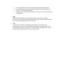
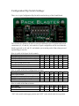
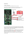
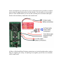
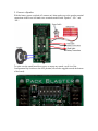
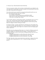
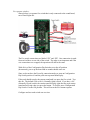
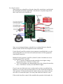
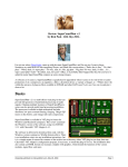
Introduction:
Congratulations on purchasing the Proton Pack: Amplified Sound Board, the only Proton
Pack sound package you will ever need!
Pack Sound Board features:
• 10W mono audio amplifier (Class D very battery efficient amplifier)
• Works with battery voltages from 9V to 14V
• Easier wiring with multiple battery connection screw terminals to be used to
distribute your single battery to other light kits
• Stereo line-in to connect your own MP3 player (mixes stereo down to mono)
• Works with separate switches or switches already being used in other light
controller kits. Does not require new switches to be installed.
• Additional combined signal and power connectors for future Pack and Wand light
kits to further simplify wiring (just plug in a single cable)
The sound board also has a couple of configuration switches on the board to select
between four main modes of operation:
1) Movie Pack Sounds
2) Movie Pack sounds with Interactive Features
3) TVG Pack sounds, cycle through 8 different TVG pack sounds
4) TVG Proton Pack Only sounds timed to match R2DEVO
One example of the Interactive movie sounds: fire soon after you hear Slimer and you get
a comment from one of the guys when you finish firing such as Ray saying "Now that
wasn't such a chore", or Peter saying "Whoa, nice shootin Tex"
TVG Pack sounds include Proton Stream, Boson Dart, Slime Blower, Slime Tether,
Stasis Stream, Shock Blast, Overload Pulse and Meson Collider. The appropriate hum
(Proton, Slime, Stasis or Overload depending on the pack sound currently selected) is
controlled by a separate HUM enable configuration switch on the sound board.
The TVG Pack sounds mode also keeps track of the pack's "temperature" and will start
beeping when overheating and will auto-vent the pack when it gets too hot. You can also
manually vent the pack to cool it down sooner.
The heating for mode 4 has been adjusted to match the R2DEVO lights. The pack does
not "remember" how long it has been since the last firing, so you always get up to 12
seconds of firing before overheating.
Only four switch inputs are needed for dynamically controlling the many included
sounds:
1. PowerUp
Controls the Pack power up and power down sounds
2. Fire
a. Press and hold for continuous firing sounds, like the Proton Stream
b. Press, hold and release for single shot sounds, like the Boson Darts in
either TVG sounds configuration
c. Quickly tap to switch between different TVG packs in TVG Pack Sounds
configuration
3. Song
When this input changes, the Ghostbusters theme song will start to play.
This works even after the pack has generated the power down sound (the battery
power must still be applied to here any sounds).
4. Vent
Controls the vent sound. Usually plays the full TVG vent sound in all
configurations. In the TVG Pack Sounds configuration, this may make a “dry
vent” sound if the pack is already cool. You must fire something for a while to
heat the pack up and then the full vent sound will play.
Configuration Dip Switch Settings:
There is a six pin Configuration Dip Switch located at the top of the Sound Board:
The switches are defined to be able to correct for different types of switches and switch
connections (#1, #2 and #4), select which of 4 pack configuration will be used when the
board is powered on (#3 and #5), and whether you want the pack to Hum when powered
up and idling or not (#6).
Here is a table of the Input Switch controls:
Description
N.O. PowerUp Switch
N.C. PowerUp Switch (Invert PowerUp)
N.O. Fire Switch
N.C. Fire Switch (Invert Fire)
N.O. Vent Switch
N.C. Vent Switch (Invert Vent)
1
OFF
ON
3
4
5
6
OFF
ON
OFF
ON
Here is a table of the Pack Configuration selections:
Description
1
Movie Pack Sounds
Movie Pack sounds w/Interactive Features
TVG Pack sounds, Cycle through 8 sounds
TVG Proton Pack only sounds
Here is a table of the Hum selection:
Description
Pack Idle Hum
No Pack Idle Hum
2
1
2
3
ON
ON
OFF
OFF
4
5
ON
OFF
ON
OFF
6
2
3
4
5
6
ON
OFF
“ON” is the switch in the upper position and “OFF” is the switch in the lower position.
Installation:
1. Battery Connections
The first connections to be made should be the battery connections.
Just one battery to rule them all! A single battery can be used to power up all of the
boards in your pack. Ideally, the battery connections would look like this:
A 9V to 14V battery pack is used to power this board and also the pack and wand light
kits if you have those. The battery is connected in parallel to all of these systems and to
simplify your wiring the sound board has provided additional screw terminal connections
to distribute the battery voltage to the other boards.
The ground connection (Black, negative or “-“) should be the same for all of the boards
in the system and can be directly connected to the negative battery terminal: the switch
only needs to control the positive connection (Red, or “+”) to the battery. There is
nothing wrong with having the switch control both the positive and the negative
connections to the battery, just more connections to wire and a more expensive switch
would be needed.
Some wand light kits may already have power connections wired up and have switched
power output to supply battery power to other boards. You do not have to rewire those
packs to work with this board, you can use that switched power from that wand lights
board as the main battery connection to the sound board:
All three of the Sound Board’s battery connections are just tied together and are used to
help you simplify your wiring: No splicing wires together, just use the screw terminals
on the sound board.
2) Test the Battery Power Connection
Now that you have the power hooked up, you can test the connections to make sure that
they are working.
To indicate that the Sound board is getting power, a Red “Power” LED indicator will
light up when battery voltage is applied:
The lights kits should work just like before you wire in the battery connections to the
Sound Board. Verify that the Power Switch does turn on and off power to the sound
board (look at the power indicator LED) and all of the light boards. Also verify that the
lights kits are operating properly before you go to the next step.
When verified, turn off the power and proceed to the next step.
3. Connect a Speaker
With the battery power switched off, connect an 8 ohm speaker up to the speaker terminal
connections in the lower left hand screw terminals marked with “Speaker”, “SP+” and
“SP-“.
To make sure the sound board does not try to output any sounds, set all six of the
Configuration Dip Switches to the OFF position (all switches toggled towards the bottom
of the board):
4. Test the Speaker
Set the Configuration switches all off. This tells the Sound Board not to make any
sounds if no switches are connected.
Set the volume control to a mid level. There is a detent in the middle of the volume
adjustment range. Set to this volume and sounds should not be too loud.
With an MP3 player
The easiest way to test the board is to play music through the Stereo Audio input.
Connect the headphone outputs from your MP3 player into the stereo Audio input
jack at the bottom of the Sound Board. You will need a cable (not supplied) with
3.5mm stereo plugs on both ends to make this connection.
Plug in the MP3 player and start music playing. Set the MP3 player’s volume to a
mid level. Now turn on the Sound Board. You should be able to hear the music
playing through the Sound Board connected speaker.
The MP3 player’s volume can be adjusted to make the music louder or softer.
The Sound board’s volume control can also adjust the sound level. This allows
you to “mix” the two sound sources together.
Without an MP3 Player
Power on the Sound board (verify power is applied by checking that the Red
Power LED is on). No sounds should be coming from the speaker.
Now turn On the Configuration Dip Switch position #3 by sliding it up towards
the top of the board. This will start the Theme song playing.
Adjust the volume control to make sure you can adjust the volume from
completely off, to crazy loud. At the maximum volume position, some speakers
may go into distortion. There is a significant amount of power available from this
audio amplifier and smaller speakers may have a hard time creating very loud
lower frequency sounds.
When the song ends, to get it started again, just toggle the Configuration Dip
Switch position #3.
4. Connect Up to Four Sound Activation Switches
You can use separate switches or the ones that are already hooked to your light kits or the
ones connected to a sound module you may be replacing. The sound board will work with
any of these switches that you already have.
You really need at least one switch (Fire) to appreciate having this board, but you can
have even more fun with up to four control switches:
Fire: Needed to capture ghosts!
Power Up/Down: Controls the pack power up and down sounds
Song: The movie theme song will play whenever this switch changes
Vent: Plays a vent sound when activated.
Type of switches: Don't be concerned about whether your pushbutton switch is an N.O or
an N.C. style - it doesn't matter! If the sounds play when the switch is in the wrong
position or isn't pressed, just change one of the configuration switches at the top of the
board. No changes in switches or wiring are needed!
For separate switches, or separate connections on a multi-pole type switch (behaves like
two or more switches connected together), two wires are needed to be connected for each
switch. For shared switches, only a single wire is needed to connect the changing signal
into the sound board.
The default setup for configuration Dip Switches #1, #2 and #4 is Off (downward) and is
designed to support N.O. (normally open) style switches. If your switches are N.C.
(normally closed) style, just move the associated Configuration Dip Switch On to invert
the incoming signal.
Configuration Dip Switch #1 set ON will invert the “PowerUp” input.
Configuration Dip Switch #2 set ON will invert the “Fire” input.
Configuration Dip Switch #4 set ON will invert the “Vent” input.
The “Song” input does not have an associated invert control since a change in the switch
is needed to start a song and both N.O. or N.C. switches will change when they are
pressed.
For separate switches:
Shown below is a separate fire switch that is only connected to the sound board,
not a Wand Lights kit:
The Fire switch connections are labeled “PU” and “PD”. One connection is made
from each of these to one side of the switch. The order is not important and if the
wire connections are swapped, the operation will still be the same.
With all six of the Configuration Dip Switches set to the off position
(downwards), power up the board and no sounds should come out.
Since we do not have the PowerUp connection made yet, turn on Configuration
Dip Switch position #1 and the pack start up sound should play.
If the pack should not play the stream sound until you press the fire switch. Test
this out. The default is for an N.O. (Normally Open) switch. If you have a N.C.
(Normally Closed) switch, the stream sound will play right after the pack startup
sound and will stop when you press the button. To fix this, move Configuration
Dip Switch #2 to the ON position. This will invert the Fire button response.
Configure and test each switch one at a time.
For shared switches:
Shown below are a shared PowerUp and a shared fire switch that is used by both
the wand lights kit and the sound board. Also shown is a separate song switch
that is only used by the Sound Board.:
Since we are sharing the battery, only the live or switched side wire from the
shared switches needs to be brought back to the sound board.
For the PowerUp and Fire switches (most common on wand light kits), we only
need to bring back one wire from each switch and connect it to the appropriate
sound board connection.
Both the PowerUp (Switch 1) and Fire (Switch 2) each of which has two screw
terminals marked "PU" and "PD".
• "PU" is used for switched wires that normally sit at a higher voltage
(because they have a "Pull Up" resistor), and
• "PD" is for switched wires that normally sit at a low voltage (because they
have a "Pull Down" resistor), like the R2DEVO lights
If you’re not sure which wire to use or what switch you have, no problem! Just
hook one wire to one of the two inputs and see if it can activate the sound in one
of the positions. If it doesn't (because the sound is always on or always off) just
move the wire to the other input. You can try that with each of the two wires.
If the switch does allow control of the sound but the operation is backwards, for
example if the fire button always fires except when pressed, just flip the
associated Configuration Dip Switch on the sound board and it will make things
right! (Dip Switch #1 for PowerUp, Dip Switch #2 for Fire and Dip Switch #4 for
Vent).
If you have a separate switch that isn't used in the wand lights, like the Song
switch, just connect the two wires to the two sound board inputs and you are
done!
5. Volume Control
There is a volume control pot built into the back side of the bottom of the board. This
allows mounting of the board to the pack mother board and the volume control shaft can
come through a small hole drilled in the motherboard allowing easy external volume
adjustment.
If you want a remote volume control you can remove that potentiometer (cut or desolder) from the board and connect wires from an external 10K to Linear potentiometer
back to the screw terminals on the lower right hand side of the sound board. You could
use the potentiometer that was removed from the board but it is not designed to be
mounted to a panel.
The external volume control connections are designed to work with really long wires and
won't affect your sound quality!
6. MP3 Player Connection
There is a black 3.5mm stereo connector at the bottom of the sound board. Just plug a
cable from your MP3 player's headphone out jack to this input jack. The MP3 music
volume is controlled by your MP3 player.
The MP3 stereo input is mixed in with the pack sounds, so they can play simultaneously.
For example, you can have your background music playing while you fire and you can
still hear both.
The MP3 volume is controlled by the MP3 player so you can make the MP3 significantly
quieter or a bit louder than the pack sounds.
FAQ:
What speakers will work with this board?
A full range 8ohm speaker is recommended with a power rating of at least 10W.
If you're going to have just one speaker, a 2 or 3 way speaker, like those used in car audio
systems might be best. With those you get a woofer, tweeter, and a midrange speaker (if
3-way) all in one package. They're designed to function as one speaker, and can match
the amp’s preferred 8ohm loading.
If you want bass, try getting a non circular speaker. Like a 6x9 or 6x8. They will
generally deliver more bass than say a 4" or 5-1/2" speaker.
If you want to use two speakers, wire two 4-ohm speakers together in series with three
connections:
1) From the sound board’s “SP –“ to the negative connection on speaker 1.
2) From the positive connection on speaker 1 to the negative connection on
speaker 2.
3) From the positive connection on speaker 2 to the sound board’s “SP+”
You get the largest output power (up to 10W) with an 8 ohm speaker load. It is designed
to work with 4 to 8 ohm speaker loads with a bit less output power when driving the
lower impedance speakers. Speaker efficiency is also a big part of how loud a speaker is,
so some 4ohm speaker could be significantly louder or quieter than some 8 ohm
speaker...
This board actually drives a decent amount of power into the speaker and a better speaker
can definitely enable a better output sound. Some speakers may have power "ratings" of
hundreds of Watts and will still provide a lot of volume with this 10W amplifier. It is
significantly more powerful and enables much higher volumes than the 1/2W amplifier
built into the sound modules that are typically used.
Wire Gauge:
What gauge wire do you recommend for running the power (I'd like to run the main
power switch to the gun toggle) and sound switches to the gun? Also for the Pot meter
please, and can you recommend a certain type of pot meter?
Worst case even if the norm isn't for all LEDs and sound to be on at max all at the same
time and just buying one size wire, not optimizing for each segment: 2.5A total for sound
and lights, 6 feet length (out to wand) and a conservative 2% voltage drop over the length
of the wire, would require #22 wire. I use #18 stranded (more flexible than single solid)
and haven't had any issues at all. Overkill!
For control and potentiometer wires just about any gauge is fine since there is very little
current involved.
Distortion Board:
In anticipation of buying a different sound kit, I purchased one of Spongeface's Distortion
Fix modules. Will that be useful or obsolete with your board?
The distortion board will not be needed since the sound module and amplifier are
designed to be used together with a single battery.
External Volume Control Potentiometer:
If you want to use an external pot you can just clip the one off the board with diagonal
cutters, and then connect a pot to the three screw terminals on the lower right side of the
board. The pot from the board could be used, but is not designed to be used as a separate
panel mounted pot.
The board uses a Linear 10K ohm pot but anything from 5K to 20K should be fine. 50K
or 100K ohm linear pots would also work, but won't behave as linearly, so may be a little
more finicky about adjusting the volume.
The volume control on this particular amp is based on a dc control voltage and has a nonlinear correction built in. An audio (logarithmic) taper pot can be used but will be more
sensitive to volume adjustments.