1
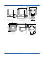
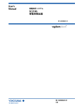
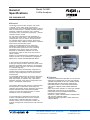
General Specifications Model FLXA21 2-Wire Analyzer GS 12A01A02-01E nGeneral The model FLXA21® 2-Wire Analyzer, one model of FLEXA® series, offers single or dual sensor measurement. The modular-designed analyzer offers 4 kinds of measurements – pH/ORP (oxidation-reduction potential), contacting conductivity (SC), inductive conductivity (ISC) or dissolved oxygen (DO) – with the respective sensor module. For dual sensor measurement, the combination of two same type sensor inputs – pH/ORP and pH/ORP (analog sensor only), SC and SC, and DO and DO – are available with two sensor modules. Dual sensor measurement offers additional functionalities; calculated data function and redundant system. Variety of calculated data from two measuring parameters is selectable for each measurement. On the redundant system built on two measuring parameters of two sensor inputs, main output parameter is automatically switched over to the second sensor output in case of the main sensor’s failure condition. Addition to conventional analog pH/ORP sensors, the analyzer FLXA21 can be connected to Yokogawa’s digital sensor, FU20F pH/ORP SENCOM Sensor. In the FLXA21 Human Machine Interface (HMI), 2-wire type analyzer FLXA21 offers easy touch screen operation and simple menu structure in 12 languages. Menus of display, execution and setting are displayed in a selected language. The analyzer FLXA21 automatically recognizes the installed sensor module and prepares the necessary menus for right configuration, even for dual sensor measurement. For immediate measurement, the FLXA21 offers quick setup functionality. The quick setup screen appears when the analyzer is powered. Only a few setups – date/time, language, basic sensor configurations and output – will start the measurement. The FLXA21 offers the best accuracy in measurement with temperature compensation functionality and calibration functionality. Sensor diagnostics and sensor wellness indication make measurement reliable. Logbook of events and diagnostic data is a useful information source for maintenance. For the wide range of industrial environment, the FLXA21 is designed with the enclosure of plastic, stainless steel or stainless steel with corrosionresistant coating. And, for hazardous location, the FLXA21 has approvals of ATEX, IECEx, FM, CSA and NEPSI. nFeatures •4 kinds of measurements; pH/ORP, SC, ISC and DO •Dual sensor measurement on 2-wire type analyzer; pH/ORP and pH/ORP, SC and SC, and DO and DO •Calculated data from dual sensor measurement •Redundant system on dual sensor measurement •Connection of digital FU20F pH/ORP SENCOM Sensor •Easy touch screen operation on 2-wire type analyzer •Simple HMI menu structure in 12 languages •Quick setup menu for immediate measurement •Indication of sensor wellness •Enclosure – plastic, stainless steel or stainless steel with corrosion-resistant coating •Hazardous location approvals – ATEX, IECEx, FM, CSA and NEPSI Yokogawa Electric Corporation 2-9-32, Nakacho, Musashino-shi, Tokyo, 180-8750 Japan Tel.: 81-422-52-5617 Fax.: 81-422-52-6792 GS 12A01A02-01E ©Copyright Mar. 2010 10th Edition Mar. 31, 2015 2 nGeneral Specifications 1.Basic ■ Measurement Object/Sensor Type • pH/Oxidation-reduction Potential (pH/ORP) (analog sensor) • Conductivity (SC) • Inductive Conductivity (ISC) • Dissolved Oxygen (DO) • pH/Oxidation-reduction Potential (pH/ORP) (digital sensor) Note: The available measurement object depends on a sensor module installed on the analyzer. ■ Analyzer Structure Module structure ●Composition of Analyzer One (1) Housing assembly One (1) or two (2) Sensor modules ●Combination of Sensor Module when two modules are installed Combinations of two same sensor modules are available; pH/ORP and pH/ORP (analog sensor) SC and SC DO and DO 2.Measurement 2-1. pH/Oxidation-reduction Potential (pH/ORP) with analog sensors ■ Input Specification Dual high impedance input (≥1012 Ω) ■ Input Range pH: -2 to 16 pH (with option /K: 0 to 14 pH) ORP: -1500 to 1500 mV rH: 0 to 100 rH Temperature: Pt1000: -30 to 140 ºC Pt100: -30 to 140 ºC 6k8: -30 to 140 ºC PTC10k: -30 to 140 ºC NTC 8k55: -10 to 120 ºC 3k Balco: -30 to 140 ºC PTC500: -30 to 140 ºC ■ Output Range pH: min. span 1 pH max. span 20 pH ORP: min. span 100 mV max. span 3000 mV rH: min. span 2 rH max. span 100 rH Temperature: min. span 25 ºC max. span 170 ºC ■ Performance (Accuracy) (The specifications are expressed with simulated inputs.) pH Linearity: ±0.01 pH Repeatability:±0.01 pH Accuracy:±0.01 pH ORP Linearity: ±1 mV Repeatability:±1 mV Accuracy:±1 mV All Rights Reserved. Copyright © 2010, Yokogawa Electric Corporation Temperature with Pt1000, 6k8, PTC10k, NTC 8k55, 3k Balco, PTC500 Repeatability:±0.1 ºC Accuracy:±0.3 ºC with Pt100 Linearity: ±0.4 ºC Repeatability:±0.1 ºC Accuracy:±0.4 ºC 2-2. Conductivity (SC) ■ Input Specification Two or four electrodes measurement with square wave excitation, using max 60m (200ft) cable (WU40/ WF10) and cell constants from 0.005 to 50.0 cm-1 ■ Input Range Conductivity: min.: 0 µS/cm max.: 200 mS x (Cell constant) (over range 2000 mS/cm) Resistivity: min.: 0.005 kΩ / (Cell constant) max.: 1000 MΩ x cm Temperature: Pt1000: -20 to 250 ºC Pt100: -20 to 200 ºC Ni100: -20 to 200 ºC NTC 8k55: -10 to 120 ºC Pb36(JIS NTC 6k): -20 to 120 ºC ■ Output Range Conductivity: min. 0.01 µS/cm max. 2000 mS/cm (max 90% zero suppression) Resistivity: min. 0.001 kΩ x cm max. 1000 MΩ x cm (max 90% zero suppression) Temperature: min. span 25 ºC max. span 270 ºC ■ Performance (Accuracy) (The specifications are expressed with simulated inputs.) Conductivity 2 µS x K cm-1 to 200 mS x K cm-1 Accuracy:±0.5%F.S. 1 µS x K cm-1 to 2 µS x K cm-1 Accuracy:±1%F.S. Resistivity 0.005kΩ / K cm-1 to 0.5MΩ /K cm-1 Accuracy:±0.5%F.S. 0.5MΩ / K cm-1 to 1MΩ /K cm-1 Accuracy:±1%F.S. Temperature with Pt1000, Pb36, Ni100 Accuracy:±0.3 ºC with Pt100, NTC 8k55 Accuracy:±0.4 ºC Temperature compensation NaCl table: ±1 % Matrix: ±3 % Step response: 90 % (< 2 decades) in 7 seconds Note: "F.S." means maximum setting value of analyzer output. "K" means cell constant. YOKOGAWA provides conductivity sensors of which cell constants are 0.1 to 10 cm-1. GS 12A01A02-01E Mar. 31, 2015-00 3 2-3. Inductive Conductivity (ISC) ■ Input Specification Compatible with the Yokogawa inductive conductivity ISC40 series with integrated temperature sensor: NTC30k or Pt1000. ■ Input Range Conductivity: 0 to 2000 mS/cm at 25 ºC reference temperature. Temperature: -20 to 140 ºC Cable length: max. 60 meters total length of fixed sensor cable + WF10(J) extension cable. Influence of cable can be adjusted by doing an AIR CAL with the cable connected to a dry cell. ■ Output Range Conductivity: min. span:100 µS/cm max. span: 2000 mS/cm (max 90% zero suppression) Temperature: min. span 25 ºC max. span 160 ºC ■ Performance (Accuracy) (The specifications are expressed with simulated inputs.) (Output span is 0-100 µS/cm or more) Conductivity: Linearity: ±(0.4 %F.S. + 0.3 µS/cm) Repeatability:±(0.4 %F.S. + 0.3 µS/cm) Temperature: ±0.3 ºC Step response: 90 % (< 2 decades) in 8 seconds Note: "F.S." means maximum setting value of analyzer output. 2-4. Dissolved Oxygen (DO) ■ Input Specification The FLXA21 accepts output from membrane covered Dissolved Oxygen sensors. These sensors can be Galvanic type, where the sensor generates its own driving voltage or Polarographic type, where the sensor uses external driving voltage from the converter. The input range is 0 to 50 µA for Galvanic sensors and 0 to 1 micro A for Polarographic sensors. For temperature compensation, the FLXA21 accepts Pt1000 (DO30 sensor) and NTC22k elements (OXYFERM and OXYGOLD sensors). ■ Input Range DO30 sensor: Dissolved Oxygen: 0 to 50 mg/l (ppm) Temperature: -20 to 150 ºC Note: Process temperature for DO30 is 0 to 40 ºC Hamilton sensors: Oxyferm: Measurement range:10 ppb to 40 ppm Temperature range: 0 to 130 ºC Oxygold G: Measurement range:2 ppb to 40 ppm Temperature range: 0 to 130 ºC Oxygold B: Measurement range:8 ppb to 40 ppm Temperature range: 0 to 100 ºC All Rights Reserved. Copyright © 2010, Yokogawa Electric Corporation ■ Output Range DO concentration: mg/l (ppm): min.: 1 mg/l (ppm) max.: 50 mg/l (ppm) ppb: min.: 1 ppb max.: 9999 ppb % saturation: min.: 10 % max.: 600 % Temperature: min. span 25 ºC max. span 170 ºC ■ Performance (Accuracy) (The specifications are expressed with simulated inputs.) Performance in ppm mode: Linearity: ±0.05 ppm or ±0.8% F.S., whichever is greater Repeatability:±0.05 ppm or ±0.8% F.S., whichever is greater Accuracy:±0.05 ppm or ±0.8% F.S., whichever is greater Performance in ppb mode: Linearity: ±1 ppb or ±0.8% F.S., whichever is greater Repeatability:±1 ppb or ±0.8% F.S., whichever is greater Accuracy:±1 ppb or ±0.8% F.S., whichever is greater Temperature Linearity: ±0.3 ºC Repeatability:±0.1 ºC Accuracy:±0.3 ºC Note: "F.S." means maximum setting value of analyzer output. 2-5. pH/Oxidation-reduction Potential (pH/ORP) with digital sensor, FU20F pH/ORP SENCOM Sensor ■ Input Specification Bi-directional digital communication (RS-485) between FU20F and FLXA21 ■ Input Range (depending on FU20F) pH: 0 to 14 pH ORP: -1500 to 1500 mV rH: 0 to 100 rH Temperature: -10 to 105 ºC ■ Output Range pH: min. span 1 pH max. span 20 pH ORP: min. span 100 mV max. span 3000 mV rH: min. span 2 rH max. span 100 rH Temperature: min. span 25 ºC max. span 170 ºC GS 12A01A02-01E Mar. 31, 2015-00 4 3.Electrical ■ Output Signal General: One output of 4-20 mA DC Note:Tolerance: ±0.02 mA Bi-directional HART digital communication, superimposed on mA (4-20mA) signal Output function: Linear or Non-linear (21-step table) Burn out function: (NAMUR 43 except ISC) Without HART/PH201G: Down: 3.6 mA (signal: 3.8 to 20.5 mA for pH/ORP, SC and DO) (signal: 3.9 to 20.5 mA for ISC) Up: 22mA With HART/PH201G: Down: 3.6 mA for pH/ORP, SC and DO Down: 3.9 mA for ISC (signal: 3.8 to 20.5 mA for pH/ORP, SC and DO) (signal: 3.9 to 20.5 mA for ISC) Up: 22mA ■ Power Supply Nominal 24 V DC loop powered system One (1) Sensor module (1 input): 16 to 40V DC (for pH/ORP (analog sensor), SC and DO) 17 to 40V DC (for ISC) 21 to 40V DC (for pH/ORP SENCOM sensor) Two (2) Sensor modules (2 inputs): 22.8 to 40V DC (for pH/ORP (analog sensor), SC and DO) Note: When the FLXA21 is used in the multi-drop mode of HART communication, the output signal is changed from 12.5 mA DC to 4 mA DC just after the power is turned on. Enough power supply for the instruments is to be provided. ●Maximum Load Resistance pH/ORP (analog sensor), SC and DO: Refer to the Figure 1. ISC and pH/ORP SENCOM sensor: Refer to the Figure 2. 2-sensor measurement 1295 R= 1000 V - 11.5 0.022 600 Digital Communication Range (HART) 16 17 18 22.8 24.7 Voltage (V) 4. Mechanical and others ■ Housing Case: • Plastic (Polycarbonate) • Stainless steel without painting • Stainless steel with epoxy coating • Stainless steel with urethane coating • Stainless steel + high anti-corrosion coating Case color and finish: Color: Silver gray (equivalent to Munsell 3.2PB7.4/1.2) (for plastic case, stainless steel cases with coating) Finish: Electropolishing (for stainless steel case without painting) Window: Polycarbonate (flexible) Window frame for stainless steel cases: Polycarbonate, color: silver gray (equivalent to Munsell 3.2PB7.4/1.2) Protection: IP66 (except Canada), Type 4X (except Canada), Type 3S/4X (Canada) ■ Plate Main name plate:inside case cover Regulation plate: on the case outside ■ Cable and Terminal Cable size: Outer diameter: 6 to 12 mm (suitable for M20 cable gland) 3.4 to 7 mm (grounding cable for plastic case) Terminal screw size: M4 torque of screw up: 1.2 N•m Wire terminal: Pin terminal, ring terminal and spade terminal can be used for analyzer’s power supply terminals and sensor terminals. For the grounding terminal on the stainless steel case, ring terminal should be used. Pin terminal: pin diameter: max. 1.9 mm Ring and spade terminal: width: max. 7.8 mm 1295 R= 1000 40 Figure 1 Supply Voltage and Load Resistance for pH/ORP (analog sensor), SC and DO All Rights Reserved. Copyright © 2010, Yokogawa Electric Corporation V - 11.5 0.022 Except SENCOM 600 516 304 250 250 0 Note: Description for a selection of language and language names are written in English. Note: Only English alphabet and numeric are available for a tag number, an additional description for each value on the display screen and passwords. Note: Only for message language on the screen, 12 languages are provided. Load resistance (Ω) Load resistance (Ω) ■ Display LCD with a touch screen: Black/White: 213 x 160 pixels Contrast adjustment available on the touch screen Message language: 12 (English, Chinese, Czech, French, German, Italian, Japanese, Korean, Polish, Portuguese, Russian and Spanish) One analyzer has all 12 languages. 0 Digital Communication Range (HART) 22.86 24.7 17 18 18.2 21 Voltage (V) 40 Figure 2 Supply Voltage and Load Resistance for ISC and pH/ORP SENCOM sensor GS 12A01A02-01E Mar. 31, 2015-00 5 ■ Cable Entry Plastic case: 1-Sensor measurement: 3 holes, M20 cable gland x 3 pcs, Sleeve x 1 pc (for grounding cable line) 2-Sensor measurement: 4 holes, M20 cable gland x 4 pcs, Sleeve x 1 pc (for grounding cable line) Stainless steel case: 3 holes, M20 cable gland x 3 pcs Close up plug x 1 pc Note: Cable gland and plug are delivered with an analyzer, but not assembled into the analyzer. ■ Mounting Mounting hardware (option): • Universal mounting kit (Note) • Pipe and wall mounting hardware • Panel mounting hardware Note: This kit contains the pipe and wall mounting hardware and the panel mounting hardware. Hood (option): • Stainless steel • Stainless steel with urethane coating • Stainless steel with epoxy coating ■ Stainless Steel Tag Plate When the additional code “/SCT” with a tag number is specified, the tag plate on which the tag number is inscribed is delivered with the analyzer. Tag plate is hanging type. ■ Conduit Adapter Using optional adapter • G1/2(quantity: 4) • 1/2NPT (quantity: 4) • M20 x 1.5 (quantity: 4) These conduit adapters are delivered with an analyzer, but not assembled into the analyzer. ■ Size of Housing Case Plastic: 144 x 144 x 151 mm (L x W x D) (without cable gland) Stainless steel case: 165 x 165 x 160 mm (L x W x D) (without cable gland) ■ Weight Approx. 1 kg (Plastic housing) Approx. 2 kg (Stainless steel housing) ■ Shipping Details Package size: Approx. 340 x 340 x 370 mm (L x W x H) ■ Ambient Operating Temperature -20 to +55 ºC ■ Storage Temperature -30 to +70 ºC ■ Humidity 10 to 90% RH at 40ºC (Non-condensing) ■ Document Following documents are delivered with an analyzer; Paper copy: Start-up Manual written in English Safety Precautions written in English CD-ROM: Start-up Manual written in English All Rights Reserved. Copyright © 2010, Yokogawa Electric Corporation User's Manual written in English Safety Regulations Manual for European region written in 25 languages General Specifications written in English Technical Information for HART Communication written in English User Setting Table of 5 kinds of measurement/sensor type written in English ■ Regulatory Compliance Safety: UL 61010-1 UL 61010-2-030 CAN/CSA C22.2 No.61010-1 EMC: EN61326-1 Class A,Table 2 (For use in industrial locations) EN61326-2-3 AS/NZS CISPR11 Korea Electromagnetic Conformity Standard Class A 한국 전자파적합성 기준 Installation altitude: 2000 m or less Category based on IEC 61010: I (Note 1) Pollution degree based on IEC 61010: 2 (Note 2) Note 1:Installation category, called over-voltage category, specifies impulse withstand voltage. Equipment with "Category I" (ex. two wire transmitter) is used for connection to circuits in which measures are taken to limit transient overvoltages to an appropriately low level. Note 2:Pollution degree indicates the degree of existence of solid, liquid, gas or other inclusions which may reduce dielectric strength. Degree 2 is the normal indoor environment. Explosion-proof (Intrinsically safe type and non-incendive) (for suffix code: -EA, -ES): ATEX Intrinsically safe approval Applicable standard Explosive Atmospheres EN 60079-0:2012/A11: 2013 Equipment General requirements EN 60079-11:2012 Equipment protection by Intrinsic safety “i” EN 60079-26:2007 Equipment with equipment protection level (EPL) Ga EN 60529:1992 Degrees of protection provided by enclosures (IP Code) Type of protection II 1G Ex ia IIC Ga Group: II Category: 1G T4: for ambient temperature:–20 to 55ºC T6: for ambient temperature:–20 to 40ºC (excluding SENCOM module) Atmosphere pressure: 80kPa (0.8bar) to 110kPa (1.1bar) Degree of Protection of the Enclosure: IP66 IECEx Intrinsically safe Applicable standard IEC 60079-0: 2011 Part 0: Equipment General requirements IEC 60079-11: 2011 Part 11: Equipment protection by Intrinsic safety “i” GS 12A01A02-01E Mar. 31, 2015-00 6 IEC 60079-26: 2006 Part 26: Equipment with equipment protection level (EPL) Ga IEC 60529: 2001 Degrees of protection provided by enclosures (IP Code) Type of protection Ex ia IIC Ga T4: for ambient temperature:–20 to 55ºC T6: for ambient temperature:–20 to 40ºC (excluding SENCOM module) Atmosphere pressure: 80kPa (0.8bar) to 110kPa (1.1bar) Degree of Protection of the Enclosure: IP66 FM Intrinsically safe and nonincendive approval Applicable standard FM-3600: 2011 Approval Standard for Electric Equipment for use in Hazardous (Classified) Locations General Requirement FM-3610: 2010 Approval Standard for Intrinsically Safe Apparatus and Associated Apparatus for Use in Class I, II, and III, Division 1, Hazardous (Classified) Locations FM-3611: 2004 Nonincendive Electrical Equipment for Use in Class I and II, Division 2 and Class III, Divisions 1 and 2, Hazardous (Classified) Locations FM-3810: 2005 Electrical Equipment for Measurement, Control and Laboratory Use NEMA 250:1991 Enclosures for Electrical Equipment (1000 Volts Maximum) ANSI/IEC 60529:2004 Degrees of protection provided by enclosures (IP Code) ANSI/ISA 60079-0 2009 Part 0: General Requirements ANSI/ISA 60079-11 2011Part 11: Equipment protection by intrinsic safety “i” Type of protection Class I, Division 1, Groups A, B, C and D (Intrinsically Safe) Class I, Division 2, Groups A, B, C and D (Nonincendive) Class I, Zone 0, in Hazardous (Classified) Locations (Intrinsically Safe) Class I, Zone 2, Group IIC, in Hazardous (Classified) Locations (Nonincendive) AEx ia IIC For all protection type, T4: for ambient temperature: -20 to 55°C T6: for ambient temperature: -20 to 40°C Atmosphere pressure: 80 kPa (0.8 bar) to 110 kPa (1.1 bar) Degree of Protection of the Enclosure: NEMA Type 4X and IP66 All Rights Reserved. Copyright © 2010, Yokogawa Electric Corporation CSA Intrinsically safe and nonincendive approval Applicable standard CAN/CSA C22.2 No. 94-M1991 Special Purpose Enclosures CAN/CSA C22.2 No. 157-92 Intrinsically Safe Equipment for Use in Hazardous Locations C22.2 No213-M1987 Non-incendive Electrical Equipment for Use in Class I, Division 2 Hazardous Locations CAN/CSA-E60079-0-07 Electrical apparatus for explosive gas atmospheres - Part 0: General requirements CAN/CSA-E60079-11-02Electrical apparatus for explosive gas atmospheres - Part 11: Intrinsic safety “i” IEC 60529:2001 Degrees of protection provided by enclosures (IP Code) Type of protection (C22.2) Class I, Division 1, Groups A, B, C and D (Intrinsically Safe) Class I, Division 2, Groups A, B, C and D (Nonincendive) For all protection type, T4: for ambient temperature: -20 to 55°C T6: for ambient temperature: -20 to 40°C Atmosphere pressure: 80 kPa (0.8 bar) to 110 kPa (1.1 bar) Ambient Humidity: 0 to 100% (No condensation) Degree of Protection of the Enclosure: Type 4X Type of protection (E60079) Ex ia IIC T4: for ambient temperature: -20 to 55°C T6: for ambient temperature: -20 to 40°C Atmosphere pressure: 80 kPa (0.8 bar) to 110 kPa (1.1 bar) Ambient Humidity: 0 to 100% (No condensation) Degree of Protection of the Enclosure: IP66 NEPSI Intrinsically safe approval Applicable Standard GB 3836.1-2010 Explosive atmospheresPart 1: Equipment - General requirements GB 3836.4-2010 Explosive atmospheresPart 4: Equipment protection by intrinsic safety “i” GB 3836.20-2010Explosive atmospheresPart 20: Equipment with equipment protection level (EPL) Ga Type of protection Ex ia IIC Ga T4: for ambient temperature: -20°C to 55°C T6: for ambient temperature: -20°C to 40°C Atmosphere pressure: 80kPa (0.8bar) to 110kPa (1.1bar) Degree of Protection of the Enclosure: IP66 GS 12A01A02-01E Mar. 31, 2015-00 7 Electrical Parameters (Ex ia) Each housing assembly (base module) and each sensor module are respectively certificated. Input parameters of sensor module meet output parameters of housing assembly. Housing assembly Input parameters Output parameters Supply and output circuit (terminals + and -): Ui, Vmax = 30 V Ii, Imax = 100 mA Pi, Pmax = 0.75 W Ci =13 nF Li = 0 mH (Linear source) Measuring module input circuit (CN2 or CN3 on Back board) Uo Vt, Voc = 13.65 V Io, It, Isc = 50 mA Po = 0.372 W Co, Ca = 80 nF Lo, La = 7.7mH pH/ORP module, SC module, and DO module Input parameters Ui, Vmax Ii, Imax Pi, Pmax Ci Li = 13.92 V = 50 mA = 0.374 W = 40 nF = 2.9 mH Output parameters Sensor input circuit (pH: terminals 11 through 19, SC: terminals 11 through 16, DO: terminals 11 through 18) Uo Vt, Voc = 11.76 V Io, It, Isc = 116.5 mA Po = 0.3424 W Co, Ca = 100 nF Lo, La = 1.7mH ISC module Input parameters Ui, Vmax Ii, Imax Pi, Pmax Ci Li = 13.92 V = 50 mA = 0.374 W = 40 nF = 7.7 mH Output parameters Sensor input circuit (terminals 11 through 17) Uo Vt, Voc = 11.76 V Io, It, Isc = 60.6 mA Po = 0.178 W Co, Ca = 100 nF Lo, La = 8 mH Control Drawing (ATEX and IECEx types) Hazardous Location ← → Non Hazardous Location Sensor 1 Sensor 2 Measuring module 1 Supply + Housing Assembly Measuring module 2 Supply - + Safety Barrier (Note 1) - (*) Note: The measuring module on this drawing means the sensor module on this General Specifications. Electrical data are as follows; Supply and output circuit (Terminals Supply + and –): Maximum Voltage (Ui) = 30V Maximum Current (Ii) = 100mA Maximum Power (Pi) = 0.75W Internal Capacitance (Ci) = 13nF Internal Inductance (Li) = 0mH Sensor input circuit (pH: terminals 11 through 19, SC: terminals 11 through 16, DO: terminals 11 thourgh 18, ISC: terminals 11 through 17, SENCOM: terminals 82, 83, 84, 86 and 87): Type of Measuring Module Maximum Voltage (Uo) Maximum Current (Io) Maximum Power (Po) External Capacitance (Co) External Inductance (Lo) pH, SC and DO 11.76 V 116.5 mA 0.3424 W 100 nF 1.7 mH ISC SENCOM 11.76 V 5.36 V 60.6 mA 106.6 mA 0.178 W 0.1423 W 100 nF 31 µF 8 mH 0.45 mH Note 1:In any safety barrier used, the output current must be limited by a resistor “R” such that Imaxout=Uz/R. Note 2:The safety barrier shall be certified by notify body EU as ATEX. Note 3:When using non isolation barrier connect (*1) to IS earthing system. Note 4:Sensor 1 and Sensor 2 shall be of passive types to be regarded as ‘simple apparatus’ or the ones individually certified with relevant parameters. Note 5:Measuring module 2 may not mounted. As for ISC module and SENCOM module, only one can be mounted. Note 6:Measuring module is placed in an enclosure with IP20 and over. SENCOM Sensor module Input parameters Ui, Vmax Ii, Imax Pi, Pmax Ci Li = 13.92 V = 50 mA = 0.374 W = 40 nF = 7.2 mH Output parameters Sensor input circuit (terminals 82, 83, 84, 86 and 87) Uo Vt, Voc = 5.36 V Io, It, Isc = 106.16 mA Po = 0.1423 W Co, Ca = 31 µF Lo, La = 0.45 mH All Rights Reserved. Copyright © 2010, Yokogawa Electric Corporation GS 12A01A02-01E Mar. 31, 2015-00 8 Control Drawing (FM type) Following contents refer “DOC. No. IKE039-A12” Class I, Division 1, Groups A, B, C, and D Class I, Zone 0 and 1, Group IIC T4 for Ta = 55°C, T6 for Ta = 40°C Hazardous Location ← → Non Hazardous Location 2 wire analyzer + Measuring module 1 Supply + Sensor 1 Safety Barrier Housing Assembly (Note 1) Supply Measuring module 2 Sensor 2 (Refer to Note 7) (*) Note: The measuring module on this drawing means the sensor module on this General Specifications. Electrical data are as follows; Input Maximum Input Voltage (Ui) = 30V Maximum Current (Ii) = 100mA Maximum Power (Pi) = 0.75W Internal Capacitance (Ci) = 13nF Internal Inductance (Li) = 0mH Sensor Input Circuit Type of Measuring Module Maximum Voltage (Uo) Maximum Current (Io) Maximum Power (Po) External Capacitance (Ca, Co) External Inductance (La, Lo) pH, SC and DO ISC 11.76 V 11.76 V 116.5 mA 60.6 mA 0.3424 W 0.178 W 100 nF 100 nF 1.7 mH 8 mH Note 1:In any safety barrier used, the output current must be limited by a resistor “R” such that Imaxout=Uz/R. Note 2:The safety barrier shall be FM Entity-Approved associated apparatus / barrier where : Barrier Voc, Uo ≤ 30V; Barrier Isc, Io ≤ 100 mA; Barrier Po ≤ 0.75W; Barrier Ca, Co ≥ 13 nF+Ccable; Barrier La, Lo ≥ Lcable Note 3:When using non isolation barrier connect (*) to IS earthing system. Note 4:pH and SC Sensor(s) are of a passive type to be regarded as ‘simple apparatus’ same as 06ATEX0218X, 06ATEX0219, IECEx KEM 06.0052X, FM3028779, 06ATEX0220X, 06ATEX0221, IECEx KEM 06.0053X or the one individually certified with relevant parameters. Note 5:ISC Sensor(s) are ISC40S of 00ATEX1067X or the one individually certified with relevant parameters. Note 6:DO Sensor(s) are of a passive type to be regarded as ‘simple apparatus’ or the one individually certified with relevant parameters. Note 7:Measuring module 2 may not mounted. As for ISC module, only one can be mounted. Note 8:Install per the National Electrical Code (NFPA 70) Note 9:WARNING - Potential electrostatic charging hazard Electrostatic charge may cause an explosion hazard. Avoid any actions that cause the generation of electrostatic charge, e.g., rubbing with a dry cloth. Note 10:As an alternative to installing the FLXA21 in Division 2 using Class I, Division 2 wiring methods, the FLXA21 may be installed in Division 2 using nonincendive field wiring in accordance with the National Electrical Code (NFPA 70) using the same parameters identified for intrinsically safe entity installations. The Associated Nonincendive Apparatus shall have nonincendive field wiring connections which are FM Approved for use in the Class I, Division 2 location. All Rights Reserved. Copyright © 2010, Yokogawa Electric Corporation Control Drawing (CSA type) Intrinsically Safe Group IIC, Zone 0 Class I, Division 1 Non-incendive Class I, Division 2, Groups A, B, C, D Hazardous Location ← → Non Hazardous Location 2 wire analyzer + Measuring module 1 Supply + Sensor 1 Safety Barrier Housing Assembly Refer to Note Supply Measuring module 2 Sensor 2 (Refer to Note 7) Note: The measuring module on this drawing means the sensor module on this General Specifications. (*) Not use safety barrier but CSA certified equipment use in Non-incendive Electrical parameters (Intrinsically safe) Housing Assembly Supply and output circuit (terminals + and -) Ui(Vmax)=30V, Ii(Imax)=100mA, Pi(Pmax)=0.75W, Ci=13nF, Li=0mH Measuring module input circuit (CN2 or CN3 on Back board) Uo(Vt,Voc)=13.65V, Io(It,Isc)=50mA, Po=0.372W, Co(Ca)=80nF, Lo(La)=7.7mH pH module, SC module and DO module Ui(Vmax)=13.92V, Ii(Imax)=50mA, Pi(Pmax)=0.374W, Ci=40nF, Li=2.9mH Sensor input circuit (terminals 11 through 19) Uo(Vt,Voc)=11.76V, Io(It,Isc)=116.5mA, Po=0.3424W, Co(Ca)=100nF, Lo(La)=1.7mH ISC module Ui(Vmax)=13.92V, Ii(Imax)=50mA, Pi(Pmax)=0.374W, Ci=40nF, Li=7.7mH Sensor input circuit (terminals 11 through 17) Uo(Vt,Voc)=11.76V, Io(It,Isc)=60.6mA, Po=0.178W, Co(Ca)=100nF, Lo(La)=8mH Installation requirements between housing assembly and safety barrier Uo≤Ui Io≤Ii Po≤Pi Co≥Ci+Ccable Lo≥Li+Lcable Voc≤Vmax Isc≤Imax Ca≥Ci+Ccable La≥Li+Lcable Uo, Io, Po, Co, Lo, Voc, Isc, Ca and La are parameters of barrier. Electrical Parameters (Nonincendive) Housing Assembly Supply and output circuit (terminals + and -) Ui(Vmax)=30V, Ci=13nF, Li=0mH Measuring module input circuit (CN2 or CN3 on Back board) Uo(Vt,Voc)=13.65V, Io(It,Isc)=50mA, Co(Ca)=80nF, Lo(La)=7.7mH pH module, SC module and DO module Ui(Vmax)=13.92V, Ci=40nF, Li=2.9mH Sensor input circuit (terminals 11 through 19) Uo(Vt,Voc)=11.76V, Io(It,Isc)=116.5mA, Co(Ca)=4uF, Lo(La)=4.5mH ISC module Ui(Vmax)=13.92V, Ci=40nF, Li=7.7mH Sensor input circuit (terminals 11 through 17) Uo(Vt,Voc)=11.76V, Io(It,Isc)=60.6mA, Co(Ca)=4uF, Lo(La)=19mH Note for Intrinsically Safe Installation: 1: In any safety barrier used, the output current must be limited by a resistor “R” such that Io=Uo/R or Isc=Voc/R. 2: The safety barrier must be CSA certified. GS 12A01A02-01E Mar. 31, 2015-00 9 3: Input voltage of the safety barrier must be less than 250Vrms/Vdc 4: When using non isolation barrier connect (*) to IS earthing system. 5: pH and SC Sensor(s) are of a passive type to be regarded as ‘simple apparatus’ same as 06ATEX0218X, 06ATEX0219, IECEx KEM 06.0052X, FM3028779, 06ATEX0220X, 06ATEX0221, IECEx KEM 06.0053X or the one individually certified with relevant parameters. 6: ISC Sensor(s) are ISC40S of 00ATEX1067X or the one individually certified with relevant parameters. 7: DO Sensor(s) are of a passive type to be regarded as ‘simple apparatus’ or the one individually certified with relevant parameters. 8: Measuring module 2 may not mounted. As for ISC module, only one can be mounted. 9: Installation should be in accordance with Canadian Electrical Code Part I and Local Electrical Code. 10:Do not alter drawing without authorization from CSA. Note for Nonincendive Installation: 1: The parameter for sensor input circuit must be taken into account when installed. 2: Installation should be in accordance with Canadian Electrical Code Part I and Local Electrical Code. 3: Do not alter drawing without authorization from CSA. Control Drawing (NEPSI types) Hazardous Location ← → Non Hazardous Location Measuring module 1 Supply + Housing Assembly Measuring module 2 Supply Sensor 2 Sensor 1 + Safety Barrier (Note 1) (*) Note: The measuring module on this drawing means the sensor module on this General Specifications. Electrical data are as follows; Maximum Voltage (Ui) = 30V Maximum Current (Ii) = 100mA Maximum Power (Pi) = 0.75W Internal Capacitance (Ci) = 13nF Internal Inductance (Li) = 0mH Note 1:The output current must be limited by a resistor “R” such that Imaxout=Uz/R (linear source). Note 2:Safety barrier certified by NEPSI should be used. Note 3:When using non isolation barrier, connect (*) to IS earthing system. Note 4:Measuring module 2 is installed when required. When measuring inductive conductivity, only one module can be installed. 5. Digital Communication ■ Kind of Digital Communication • HART or PH201G dedicated distributor Note: Only one kind of digital communication is available for one analyzer. ■ Output Value Parameter (HART) Four value parameters (measured values) are available for one digital communication. • For 1-sensor measurement, these parameters are measured values. • For 2-sensor measurement, refer to the next item. ■ Digital Communication of 2-Sensor Measurement (HART) Even when two sensor modules are installed, only one digital communication is available for 2-sensor measurement. Four value parameters can be selected from the followings; Measured values of two sensors Calculated data of 2-sensor measurement Redundant system output ■ Specific Contact Output with dedicated distributor, model PH201G (Style B) The distributor, model PH201G, is designed to connect with the 2-Wire Analyzer. This distributor supplies drive power to the analyzer and receives simultaneously 4-20 mA DC signal from the analyzer. This signal is converted to 1-5 V DC signal in the distributor. This distributor also receives digital signals superimposed on the 4-20 mA DC signal, and provides contact outputs Input/Output signal: Number of available drive/signal point: 1 Output signal:1-5 V DC (2 points) (Note) Load resistance: 2 kΩ or less (1-5 V DC output) Isolation system: Loop isolation type Note: Two output signals for one analyzer's analog output are provided. Two 1-5 V DC output signals are same. Contact output: Contact rating: 250 V AC, maximum 100 VA 220 V DC, maximum 50 VA Hold contact output: NC contact, normally energized Contact closes when power is off or during Hold situation. Fail contact output: NC contact, normally energized Contact closes when power is off or during Fail/Warning conditions. Wash contact output: NO contact Contact closes during wash cycles. Regulatory Compliance Korea Electromagnetic Conformity Standard Class A 한국 전자파적합성 기준 All Rights Reserved. Copyright © 2010, Yokogawa Electric Corporation GS 12A01A02-01E Mar. 31, 2015-00 10 6. Model & Suffix Codes Model FLXA21 Suffix code Option code Description ······················································································· ···················· 2-Wire Analyzer Power supply -D Housing ···················· Always -D -P -S -U -E -W Display Type 1st input 2nd input (Note 1) Output (Note 10) ················· ················· ················· ················· ················· -D ···················· Anti-glare LCD -AA -EA -ES -EG -AQ -AR -EQ -ER -P1 -C1 -C5 -D1 -S1 -NN -P1 -C1 -D1 -A Language set (Note 2) Country (Note 3) ················· ················· ················· ················· ················· ················· ················· ················· General purpose ATEX, IECEx, FM, CSA, NEPSI (Note 5) ATEX, IECEx for SENCOM sensor (Note 9) KOSHA (Note 12) General purpose for EAC with PA (Note 13) General purpose for EAC (Note 14 EACEx with PA (Note 15) EACEx (Note 16) ···················· ···················· ···················· ···················· ···················· pH/ORP (Note 7) Conductivity (SC) Inductive conductivity (ISC) Dissolved oxygen (DO) pH/ORP (SENCOM sensor) (Note 8) ···················· ···················· ···················· ···················· Without input pH/ORP (Note 7) Conductivity (SC) Dissolved oxygen (DO) ···················· 4-20 mA + HART -N — Plastic Stainless steel Stainless steel + urethane coating Stainless steel + epoxy coating Stainless steel + high anti-corrosion coating (Note 11) ···················· Always -N -LA ···················· English and 11 languages -N -J ···················· Global except Japan ···················· Japan -NN ···················· Always -NN — Option Mounting hardware Hood Tag plate Conduit adapter Measurement law /UM /U /PM /H6 /H7 /H8 /SCT /CB4 /CD4 /CF4 /K Universal mounting kit (Note 4) Pipe and wall mounting hardware Panel mounting hardware Hood, stainless steel Hood, stainless steel + urethane coating Hood, stainless steel + epoxy coating Stainless steel tag plate Conduit adapter (G1/2 x 4 pcs) Conduit adapter (1/2NPT x 4 pcs) Conduit adapter (M20 x 1.5 x 4 pcs) With Measurement Law certificate (Note 6) Notes: 1: When a 2nd input is selected, only the same kind of the 1st input is available. For example, when a 1st input is “-P1”, the 2nd input must be the same “-P1”. The combination of ISC and ISC is not available. And, the combination of SENCOM sensor and SENCOM sensor is not available, either. 2: These languages are message languages on the analyzer’s display. One analyzer has English and 11 languages. All languages are as follows; English, Chinese, Czech, French, German, Italian, Japanese, Korean, Polish, Portuguese, Russian and Spanish. 3: When an analyzer is used in Japan, it must meet the Japanese Measurement Law. Only SI units must be used on the analyzer and its documents in Japan. 4: The universal mounting kit contains the pipe and wall mounting hardware (/U) and the panel mounting hardware (/PM). 5: The type “-EA” is intrinsically safe type of ATEX, IECEx, FM, CSA and NEPSI, and non-incendive of FM and CSA. Temperature classes are T4 and T6. The type “-EA” cannot be used with SENCOM sensor. For SENCOM sensor, select “-ES”. 6: The analyzer with Japanese Measurement Law certificate is available only for the following model; FLXA21-D-[Housing code]-D-AA-P1-NN-A-N-LA-J-NN/[option code except /K]/K Only one pH measurement with an analog sensor is certified. The output signal of 4 - 20 mA is certified. HART communication is not certified. 7: This input is to be come from an analog pH/ORP sensor. All Rights Reserved. Copyright © 2010, Yokogawa Electric Corporation GS 12A01A02-01E May 07, 2015-02 11 8: 9: 10: 11: 12: 13: 14: 15: 16: When the analyzer is connected with the digital sensor, FU20F pH/ORP SENCOM Sensor, only the following model is available; Type: General purpose (-AA) and explosion-proof (-ES). Explosion-proof (-ES) is available only for ATEX and IECEx 2nd input:Without input (-NN) Option: except “/K” The type “-ES” is intrinsically safe type of ATEX, IECEx for SENCOM sensor. Temperature class is T4. The FLXA21 has other output types of “FOUNDATION Fieldbus” communication (suffix code: -F) and “PROFIBUS PA” communication (suffix code: -P). Refer to GS 12A01A02-71E and GS 12A01A02-72E. The housing with stainless steel + high anti-corrosion coating is available for the type “-AA” and “-ES”. The type “-EG” intrinsically safe type of KOSHA for Korea. Temperature class is T4. The type “-AQ” is General purpose type of EAC with Pattan Approval for Russia. The type “-AR” is General purpose type of EAC for Kazakhstan and Belarus. The type “-EQ” intrinsically safe type of EAC with Pattan Approval for Russia. Temperature class is T4. The type “-EQ” cannot be used with SENCOM sensor. The type “-ER” intrinsically safe type of EAC for Kazakhstan and Belarus. Temperature class is T4. The type “-ER” cannot be used with SENCOM sensor. nDimensions and Mounting Plastic Housing 151 141 144 80 137 80 144 22.5 Unit: mm For sensor 1 cable 4-M6 depth 5 26.5 26.5 24.7 (For sensor 2 cable) For power supply 1 44.9 20.2 For grounding cable 137 FB4_01.ai Conduit Adapter (Option code: /CB4, /CD4, /CF4) Unit: mm(inch) Nut Approx. 55(2.2") 49 (1.93") Adapter Packing G1/2 screw (/CB4), 1/2 NPT screw (/CD4) M20x1.5 screw (/CF4) All Rights Reserved. Copyright © 2010, Yokogawa Electric Corporation F0204.ai GS 12A01A02-01E May 07, 2015-02 12 (Note)The universal mounting kit (/UM) contains the pipe and wall mounting hardware (/U) and the panel mounting hardware (/PM). Panel mounting hardware (Option code: /PM, /UM) Panel thickness 1 to 12 Unit: mm +1 135 138 0 138 0 +1 2-M5 length 35 100 195 4-M6 * 185 Spacing panel cutout *: Tighten the four screws to a torque of 2 N•m. 178 FB4_03.ai Wall mounting hardware (Option code: /U, /UM) Unit: mm 164 144 4-M6 * 50 For wall mounting 3-ø10 holes 15 200 224 144 13 70 100 *: Tighten the four screws to a torque of 2 N•m. FB4_02.ai Note: The wall on which the analyzer is mounted should be strong enough to bear the weight of more than 8 kg. Pipe mounting hardware (Option code: /U, /UM) Unit: mm (205) 151 Pipe 50A (ø60.5) 144 50 200 174 4-M6 * M8 U-bolt Pipe mounting (Horizontal) Pipe mounting (Vertical) *: Tighten the four screws to a torque of 2 N•m. All Rights Reserved. Copyright © 2010, Yokogawa Electric Corporation 100 FB4_04.ai GS 12A01A02-01E Mar. 31, 2015-00 13 Stainless steel hood (Option code: /H6, /H7, /H8) 184 144 9 Unit: mm (50) 199 144 57 72 220 (70) (100) FB4_05.ai Stainless Steel Housing 80 137 165 32.5 For sensor 1 cable (For sensor 2 cable) 80 165 Unit: mm 160 150 4-M6 depth 5 26.5 25.3 Plate (Only with coating) For power supply 44 22.2 137 FB4_06.ai Conduit Adapter (Option code: /CB4, /CD4, /CF4) Unit: mm(inch) Nut Approx. 55(2.2") 49 (1.93") Adapter Packing G1/2 screw (/CB4), 1/2 NPT screw (/CD4) M20x1.5 screw (/CF4) All Rights Reserved. Copyright © 2010, Yokogawa Electric Corporation F0204.ai GS 12A01A02-01E Mar. 31, 2015-00 14 (Note)The universal mounting kit (/UM) contains the pipe and wall mounting hardware (/U) and the panel mounting hardware (/PM). Panel mounting hardware (Option code: /PM, /UM) Panel thickness 1 to 12 Unit: mm +1 134 2-M5 length 35 138 0 +1 Plate (Only with coating) 138 0 100 195 4-M6 * 185 Spacing panel cutout *: Tighten the four screws to a torque of 2 N•m. 178 FB4_08.ai Wall mounting hardware (Option code: /U, /UM) 173 165 4-M6 * *: Tighten the four screws to a torque of 2 N•m. 15 For wall mounting 3-ø10 holes 50 200 234.5 165 13 Unit: mm 70 100 FB4_07.ai Note: The wall on which the analyzer is mounted should be strong enough to bear the weight of more than 8 kg. All Rights Reserved. Copyright © 2010, Yokogawa Electric Corporation GS 12A01A02-01E Mar. 31, 2015-00 15 Pipe mounting hardware (Option code: /U, /UM) Pipe 50A (ø60.5) (214) 165 Unit: mm 200 184.5 4-M6 * 50 160 Pipe mounting (Horizontal) Pipe mounting (Vertical) M8 U-bolt *: Tighten the four screws to a torque of 2 N•m. 100 FB4_09.ai Stainless steel hood (Option code: /H6, /H7, /H8) 220 Unit: mm 9 (50) 199 165 57 72 184 165 (70) (100) All Rights Reserved. Copyright © 2010, Yokogawa Electric Corporation FB4_10.ai GS 12A01A02-01E Mar. 31, 2015-00 16 nWiring Diagrams WTB10 or BA10 Terminal box *6 Case of Distributor PH201G (Style B) FLXA21 2-Wire Analyzer – CMN CMN + B D H C F A n n n n n n n n n *4 Sensor Output 1 (1-5V DC) *1 + – WTB10 or BA10 Terminal box *6 *2 (Stainless steel housing) Output 2 (1-5V DC) (*3) *5 n n n n n n n n n b *3 a HOLD *2 (Plastic housing) L N c e d f FAIL *7 Power supply 20 to 130V DC or 80 to 138V AC, 47 to 63Hz WASH Case of Distributor SDBT – + B A – + H F Output 2 (1-5V DC) Sensor Output 1 (1-5V DC) *7 L N + 1 – 2 Power supply 20 to 130V DC or 80 to 138V AC, 47 to 63Hz (*3) *1: Use a 2-wire shielded cable with an outside diameter of 6 to 12 mm. *2: Connect the analyzer to ground. (Class D ground: 100 ohm or less) The way of connecting the grounding cable varies depending on the plastic housing and stainless steel housing. In the case of the plastic housing, connect the grounding cable to the terminal of the power module inside, and in the case of the stainless steel housing, connect the grounding cable to the terminal of the housing. Use a cable with an outside diameter of 3.4 to 7 mm for the grounding line of the plastic housing. Although, on the stainless steel housing, the ground terminal symbol is (protective ground), the ground is really functional ground. *3: This line is connected to a distributor or 24V DC power supply. *4: Terminal numbers for each sensor module are shown below. *5: Two modules of the same kind of measurement/sensor type can be installed. When measuring inductive conductivity or pH/ORP with the SENCOM sensor, only one module can be installed. *6: The terminal box may be necessary depending on the sensor cable length and the distance between the analyzer and the sensor. The SENCOM sensor is to be connected directly to the analyzer without a terminal box. *7: Two outputs, output 1 and output2, of PH201G or SDBT are same signals. 11 12 14 18 13 17 19 15 16 PH Module PH 11 12 13 14 15 16 NC SC Module SC 11 12 13 17 14 16 15 ISC Module ISC 11 12 16 15 13 14 17 DO Module 18 NC DO NC 82 83 84 NC 86 SENCOM Module All Rights Reserved. Copyright © 2010, Yokogawa Electric Corporation 87 SENCOM GS 12A01A02-01E Mar. 31, 2015-00 17 nInquiry Specifications Sheet for FLXA21 2-Wire Analyzer Make inquiries by placing checkmarks () in the pertinent boxes and filling in the blanks. 1. General Information Company name Contact Person; Department; Plant name; Measurement location; Purpose of use; Indication, Recording, Alarm, Control 2. Measurement Conditions (1) Process temperature; to Normally (2) Process pressure; to Normally (3) Flow rate; to Normally (4) Flow speed; to Normally (5) Slurry or contaminants; No, Yes (6) Name of process fluid; (7) Components of process fluid; (8) Others; [°C] [kPa] [l/min] [m/s] 3. Installation Site (1) Ambient temperature; to (2) Location; Outdoors, Indoors (3) Others; [°C] 4. Requirements 1st Input; pH/ORP (analog sensor) Conductivity (SC) Inductive conductivity (ISC) Dissolved oxygen (DO) pH/ORP (digital sensor, FU20F) 2nd Input; With (same as 1st Input) Without 4.1 pH/ORP (analog sensor) 1st Input (1) Measuring range; pH 0 to 14 ORP to mV (2) Transmission output; 4 to 20 mA DC pH ORP Temperature (3) System configuration selection; Electrode, Holder, pH Converter, Cleaning system, Terminal box, Accessories (4) Electrode cable length; 3m, 5m, 7m, 10m, 15m, 20m, m (5) Electrode operating pressure; 10 kPa or less, More than 10 kPa (6) Type of holder; Guide pipe, Submersion, Flow-through, Suspension, Angled floating ball, Vertical floating ball (7) Cleaning method; No cleaning, Ultrasonic cleaning, Jet cleaning, Brush cleaning (8) Sample temperature; -5 to 105°C, -5 to 100°C, -5 to 80°C (9) Others; 2nd Input (1) Measuring range; pH 0 to 14 ORP to mV (2) Transmission output; 4 to 20 mA DC pH ORP Temperature (3) System configuration selection; Electrode, Holder, pH Converter, Cleaning system, Terminal box, Accessories (4) Electrode cable length; 3m, 5m, 7m, 10m, 15m, 20m, m (5) Electrode operating pressure; 10 kPa or less, More than 10 kPa (6) Type of holder; Guide pipe, Submersion, Flow-through, Suspension, Angled floating ball, Vertical floating ball (7) Cleaning method; No cleaning, Ultrasonic cleaning, Jet cleaning, Brush cleaning (8) Sample temperature; -5 to 105°C, -5 to 100°C, -5 to 80°C (9) Others; All Rights Reserved. Copyright © 2010, Yokogawa Electric Corporation GS 12A01A02-01E Mar. 31, 2015-00 18 4.2 Conductivity 1st Input (1) Measuring range; (2) Transmission output;4 to 20 mA DC -1 -1 (3) Detector/sensor; SC4AJ Two electrode system (0.02 cm ) Two electrode system (0.1 cm ) -1 -1 SC8SG Two electrode system (0.01 cm ) Two electrode system (10 cm ), -1 Four electrode system (10 cm ) -1 -1 SC210G Two electrode system (0.05 cm ) Two electrode system (5 cm ) (4) Detector/sensor mounting method; SC4AJ Adapter mounting, Welding socket, Welding clamp SC8SG Screw-in, Flow-through SC210G Screw-in, Flange, Flow-through, Screw-in with gate valve (5) Electrode cable length; SC4AJ 3m, 5m, 10m, 20m SC8SG 5.5m, 10m, 20m SC210G 3m, 5m, 10m, 15m, 20m (6) Others; 2nd Input (1) Measuring range; (2) Transmission output;4 to 20 mA DC -1 -1 (3) Detector/sensor; SC4AJ Two electrode system (0.02 cm ) Two electrode system (0.1 cm ) -1 -1 SC8SG Two electrode system (0.01 cm ) Two electrode system (10 cm ), -1 Four electrode system (10 cm ) -1 -1 SC210G Two electrode system (0.05 cm ) Two electrode system (5 cm ) (4) Detector/sensor mounting method; SC4AJ Adapter mounting, Welding socket, Welding clamp SC8SG Screw-in, Flow-through SC210G Screw-in, Flange, Flow-through, Screw-in with gate valve (5) Electrode cable length; SC4AJ 3m, 5m, 10m, 20m SC8SG 5.5m, 10m, 20m SC210G 3m, 5m, 10m, 15m, 20m (6) Others; 4.3 Inductive conductivity (1) Measuring range; (2) Transmission output;4 to 20 mA DC (3) System configuration selection; ISC40GJ Sensor, Holder, Converter, BA20 Terminal box, WF10J Extension cable (4) Sensor mounting method; ISC40FDJ Immersion holder, ISC40FFJ Flow-through holder, ISC40FSJ Direct insertion adapter (5) ISC40GJ Sensor cable length; 5m, 10m, 15m, 20m (6) WF10J Extension cable length; 5m, 10m, 20m, 30m, 40m (7) Others; All Rights Reserved. Copyright © 2010, Yokogawa Electric Corporation GS 12A01A02-01E Mar. 31, 2015-00 19 4.4 Dissolved oxygen 1st Input (1) Measuring range; 0 to 50 mg/L (2) Transmission output;4 to 20 mA DC (3) System configuration selection; Electrode, Holder, Converter, Cleaning system, Terminal box, Maintenance parts set, Calibration set (4) Electrode cable length; 3m, 5m, 10m, 15m, 20m (5) Type of holder; Guide pipe, Submersion, Flow-through, Suspension, Angled floating ball, Vertical floating ball (6) Cleaning method; No cleaning, Jet cleaning (7) Others; 2nd Input (1) Measuring range; 0 to 50 mg/L (2) Transmission output;4 to 20 mA DC (3) System configuration selection; Electrode, Holder, Converter, Cleaning system, Terminal box, Maintenance parts set, Calibration set (4) Electrode cable length; 3m, 5m, 10m, 15m, 20m (5) Type of holder; Guide pipe, Submersion, Flow-through, Suspension, Angled floating ball, Vertical floating ball (6) Cleaning method; No cleaning, Jet cleaning (7) Others; 4.5 pH/ORP (digital sensor, FU20F) (1) Measuring range; pH 0 to 14 ORP to mV (2) Transmission output; 4 to 20 mA DC pH ORP Temperature (3) System configuration selection; Electrode, Holder, pH Converter, Cleaning system, Accessories (4) Electrode cable length; 3m, 5m, 10m, 20m, m (5) Electrode operating pressure; 10 kPa or less, More than 10 kPa (6) Type of holder; Guide pipe, Submersion, Flow-through, Suspension, Angled floating ball, Vertical floating ball (7) Cleaning method; No cleaning, Jet cleaning (8) Sample temperature; -5 to 105°C, -5 to 100°C, -5 to 80°C (9) Others; All Rights Reserved. Copyright © 2010, Yokogawa Electric Corporation Subject to change without notice. GS 12A01A02-01E Mar. 31, 2015-00