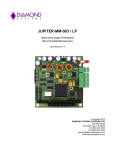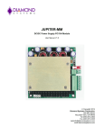
1
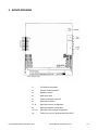
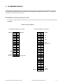
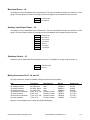
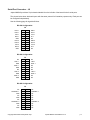
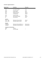
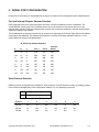
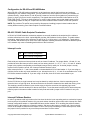
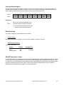
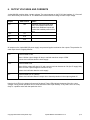
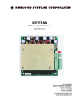
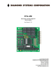
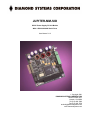
JUPITER-MM-SIO DC/DC Power Supply PC/104 Module With 2 RS-232/422/485 Serial Ports User Manual V1.3 Copyright 2001 DIAMOND SYSTEMS CORPORATION 8430-D Central Ave. Newark, CA 94560 Tel (510) 456-7800 Fax (510) 456-7878 [email protected] www.diamondsystems.com TABLE OF CONTENTS 1. DESCRIPTION ...................................................................................................................................... 3 2. BOARD DRAWING ............................................................................................................................... 4 3. I/O HEADER PINOUTS ......................................................................................................................... 5 PC/104 BUS CONNECTORS....................................................................................................................... 5 MAIN INPUT POWER – J4 .......................................................................................................................... 6 AUXILIARY INPUT/OUTPUT POWER – J5 ...................................................................................................... 6 SHUTDOWN CONTROL – J3 ....................................................................................................................... 6 SERIAL PORT CONNECTOR – J6................................................................................................................. 7 4. SERIAL PORT CONFIGURATION........................................................................................................ 9 PORT AND INTERRUPT REGISTER ADDRESS SELECTION ............................................................................... 9 SERIAL PROTOCOL SELECTION .................................................................................................................. 9 CONFIGURATION FOR RS-422 AND RS-485 MODES................................................................................... 10 RS-422 / RS-485 CABLE ENDPOINT TERMINATION .................................................................................... 10 INTERRUPT LEVELS ................................................................................................................................ 10 INTERRUPT SHARING .............................................................................................................................. 10 INTERRUPT PULLDOWN RESISTOR ........................................................................................................... 10 INTERRUPT STATUS REGISTER ................................................................................................................ 11 DEFAULT SETTINGS ................................................................................................................................ 11 RS-485 TRANSMITTER CONTROL............................................................................................................. 11 5. INSTALLATION .................................................................................................................................. 12 6. OUTPUT VOLTAGES AND CURRENTS ............................................................................................ 13 7. SPECIFICATIONS............................................................................................................................... 14 Copyright 2001 Diamond Systems Corp. Jupiter-MM-SIO User Manual V1.3 p. 2 JUPITER-MM-SIO DC/DC Power Supply PC/104 Module With 2 Serial Ports 1. DESCRIPTION JUPITER-MM-SIO is a PC/104-format power supply module designed for mobile as well as stationary embedded applications. The JUPITER-MM-SIO design incorporates a high efficiency DC/DC converter circuit to provide power with minimum losses. Power supply performance and reliability have been optimized through the use of precision surface mount components. The Jupiter-MM-SIO series contains significant advances in mobile embedded power supply technology: ♦ Surface Mount Components To the maximum extent possible, surface mount components have been used in the design, to lower the profile and improve ruggedness. An additional benefit to is the improved ability to use the PCB planes as a heat sink. ♦ High Efficiency, High-Frequency Design Efficiency is as high as 92 percent, lowering input power requirements as well as heat generation. The 200KHz switching circuit allows the use of smaller inductors, reducing size and weight and allowing the board to fully fit within the PC/104 height requirements. ♦ Advanced Design - No Heat Sink is required Eliminating the heatsink reduces total weight, a significant benefit for airborne applications. ♦ Remote On/Off Control The supply can be turned on and off with an external contact closure through an auxiliary connector. ♦ Dual Multiprotocol Serial Ports Two 16450-compatible serial ports offer RS-232, RS-422, and RS-485 protocol serial communications at speeds up to 115.2kbaud. In many applications this can reduce the need for an additional board, further reducing total system cost, size, and weight. ♦ Extended Temperature Operation Extended temperature (-40 to +85oC) operation is standard, enabling the supplies to be used in vehicle applications and other harsh environments. Copyright 2001 Diamond Systems Corp. Jupiter-MM-SIO User Manual V1.3 p. 3 2. BOARD DRAWING J1 PC/104 8-bit bus header J2 PC/104 16-bit bus header J3 Shutdown control J4 Main power input J5 Power input/output connector J6 Serial port connector J7, J8 Serial port protocol configuration J9 Serial port address configuration J10, J11 Serial port interrupt level configuration J12 Factory use only (for programming Xilinx PLD) Copyright 2001 Diamond Systems Corp. Jupiter-MM-SIO User Manual V1.3 p. 4 3. I/O HEADER PINOUTS Jupiter-MM-SIO provides connections for input, input/output, remote on/off control, and PC/104 bus. All power I/O connectors except the PC/104 bus connectors are located along the right side of the board. The serial port connector is on the left side of the board. PC/104 Bus Connectors for Power Lines For simplicity, signal names are only shown for pins with power connections on board. All remaining pins are not shown. View from Top of Board J2: PC/104 16-bit bus connector Ground +5V Ground Ground D0 D1 D2 D3 D4 D5 D6 D7 D8 D9 D10 D11 D12 D13 D14 D15 D16 D17 D18 D19 C0 C1 C2 C3 C4 C5 C6 C7 C8 C9 C10 C11 C12 C13 C14 C15 C16 C17 C18 C19 J1: PC/104 8-bit bus connector Ground Key (pin cut) Ground Copyright 2001 Diamond Systems Corp. A1 A2 A3 A4 A5 A6 A7 A8 A9 A10 A11 A12 A13 A14 A15 A16 A17 A18 A19 A20 A21 A22 A23 A24 A25 A26 A27 A28 A29 A30 A31 A32 B1 B2 B3 B4 B5 B6 B7 B8 B9 B10 B11 B12 B13 B14 B15 B16 B17 B18 B19 B20 B21 B22 B23 B24 B25 B26 B27 B28 B29 B30 B31 B32 Ground +5V -5V -12V +12V Key (pin cut) +5V Ground Ground Jupiter-MM-SIO User Manual V1.3 p. 5 Main Input Power – J4 J4 consists of a 2-pin detachable screw terminal block. The screw terminals will accept wire sizes from 18-28 gauge. The input polarity is shown in markings on the board adjacent to the board-mounted connector. 1 2 Positive Input Input Return Auxiliary Input/Output Power – J5 J5 consists of a 7-pin detachable screw terminal block. The screw terminals will accept wire sizes from 18-28 gauge. The input polarity is shown in markings on the board adjacent to the board-mounted connector. 1 2 3 4 5 6 7 Positive Input Input Return +12V Output +5V Output Ground -5V Output -12V Output Shutdown Control – J3 Shutdown may be implemented by shorting the two pins on J3 together (or driving a logic 0 into pin 1). 1 2 Shutdown input Ground Mating Connectors for J3, J4, and J5 The part numbers for several compatible mating connectors are shown below. Item J3 board mount connector J3 mating connector J3 mating connector J3 mating connector J4 board mount connector J4 screw terminals J5 board mount connector J5 screw terminals Description 2-pin friction lock 26 AWG, Blue 24 AWG, White 22 AWG, Red 2 pins, 0.15”, RA 2 pins, 0.15” 7 pins, 0.15”, RA 7 pins, 0.15” Manufacturer Amp Amp Amp Amp Phoenix Contact Phoenix Contact Phoenix Contact Phoenix Contact Mfr No. 640457-2 640622-2 640621-2 640620-2 1803277 1803578 1803329 1803620 Digi-Key No. A1926 A19112 A19091 A19070 277-1206 277-1161 277-1211 277-1166 Digi-Key is at www.digikey.com or (800) 344-4539 (800-Digikey). Copyright 2001 Diamond Systems Corp. Jupiter-MM-SIO User Manual V1.3 p. 6 Serial Port Connector – J6 Jupiter-MM-SIO provides a 20-pin header labeled J6 on the left side of the board for the 2 serial ports. The pinouts below show both serial ports with the same protocol for illustration purposes only. Each port can be configured independently. See the following page for signal definitions. RS-232 Configuration: J6 DCD 1 RXD 1 TXD 1 DTR 1 GND DCD 2 RXD 2 TXD 2 DTR 2 GND 1 3 5 7 9 11 13 15 17 19 2 4 6 8 10 12 14 16 18 20 DSR 1 RTS 1 CTS 1 RI 1 NC DSR 2 RTS 2 CTS 2 RI 2 NC RS-422 Configuration: J6 NC TXD+ 1 GND RXD+ 1 GND NC TXD+ 2 GND RXD+ 2 GND 1 3 5 7 9 11 13 15 17 19 2 4 6 8 10 12 14 16 18 20 NC TXD- 1 RXD- 1 NC NC NC TXD- 2 RXD- 2 NC NC RS-485 Configuration: J6 NC TXD/RXD+ 1 GND NC GND NC TXD/RXD+ 2 GND NC GND 1 3 5 7 9 11 13 15 17 19 2 4 6 8 10 12 14 16 18 20 NC TXD/RXD- 1 NC NC NC NC TXD/RXD- 2 NC NC NC Copyright 2001 Diamond Systems Corp. Jupiter-MM-SIO User Manual V1.3 p. 7 Serial Port Signal Definitions: Signal Name RS-232: DCD DSR RXD RTS TXD CTS DTR RI Definition Direction Data Carrier Detect Data Set Ready Receive Data Request To Send Transmit Data Clear To Send Data Terminal Ready Ring Indicator Input Input Input Output Output Input Output Input RS-422: TXD+, TXDRXD+, RXD- Differential Transmit Data Differential Receive Data Output Input RS-485: TXD/RXD+ TXD/RXD- Differential Transmit/Receive + Differential Transmit/Receive - Bi-directional Bi-directional Common to all protocols: GND Ground NC Not Connected Copyright 2001 Diamond Systems Corp. --- Jupiter-MM-SIO User Manual V1.3 p. 8 4. SERIAL PORT CONFIGURATION Please refer to the drawing of Jupiter-MM-SIO on page 4 for locations of the configuration items mentioned here. Port and Interrupt Register Address Selection Each peripheral board in the computer system must have a unique I/O address or block of addresses. The Jupiter-MM-SIO actually uses five I/O address blocks: one for each of the four serial ports and one for the interrupt status register. Each port’s address block consists of 8 consecutive addresses, while the interrupt status register occupies a single address. The I/O addresses are set with jumper block J9, located at the right edge of the board. Eight different I/O address combinations are selectable. The address shown below for each port is the base address of that port, i.e. the lowest address of the port’s I/O address block. J9: Serial Port Address Selection A B C Port 1 Port 2 Interrupt Status In In In 3F8 2F8 220 Out In In 3E8 2E8 220 In Out In 380 388 224 Out Out In 240 248 224 In In Out 100 108 240 Out In Out 120 128 244 In Out Out 140 148 248 Out Out Out 160 168 24C Serial Protocol Selection Different protocol configurations are possible for each serial port. Protocol selection is made by installing jumpers in the positions indicated below in the configuration headers J7 or J8, depending on the port. J7: Port 1 protocol configuration J8: Port 2 protocol configuration Protocol 1 2 3 4 5 6 RS-232 Out In Out Out In Out RS-422 Int Out Int Out Out Out RS-485 In Out Out In Out In Copyright 2001 Diamond Systems Corp. Jupiter-MM-SIO User Manual V1.3 p. 9 Configuration for RS-422 and RS-485 Modes When RS-422 or RS-485 modes are selected, not all signals are used by the line drivers and receivers. Depending on your software configuration, you may need to force some inputs true so that your software will operate correctly. Jumper blocks J7 and J8 provide a means to force the input signals true (connect them to ground, or logic 0) for ports 1 and 2, respectively. The signals that can be controlled in this fashion are CTS, DCD, DSR, and RI. To force an input signal true on a port, install a jumper next to that signal’s name on the corresponding header for that port. Jumpers should not be installed in these locations for RS-232 operation. NOTE: The positions TX and RX are not used for this purpose. Installing jumpers in these locations has an entirely different meaning. See Cable Endpoint Termination below. RS-422 / RS-485 Cable Endpoint Termination In RS-422 or RS-485 networks, termination resistors are normally installed at the endpoints of the cables to minimize reflections on the lines. Jupiter-MM-SIO provides 120Ω resistors for this purpose. To enable resistor termination, install jumpers in the locations TX and RX of J7 or J8 for ports 1 or 2 respectively. Termination is only needed, and should only be used, at the cable endpoints. Installing termination resistors at additional points in the network may cause overloading and/or failure of the line drivers. Interrupt Levels J10: Port 1 interrupt configuration J11: Port 2 interrupt configuration Each serial port requires an interrupt level as well as a base I/O address. Two jumper blocks, J10 and J11, are provided to select the interrupt level for each port from among levels 9, 3, 4, 5, 6, 7, 10, 11, 12, and 15. Install a jumper in the position corresponding to the desired interrupt level for each port. A second jumper is usually required in the R position as well; see “Interrupt Pulldown Resistor” below. Note: Interrupt levels 3 – 7 and 9 are available on the standard 8-bit PC/104 bus header J1. If you are using an 8-bit bus, these are the only levels available to you. Interrupt levels 10, 11, 12, and 15 are available on the 16-bit PC/104 bus extension header J2. If you are using a 16-bit bus, then all 10 levels are available to you. Interrupt Sharing On the PC/104 bus, a single interrupt level may be shared by multiple devices. A device requesting service drives the line to a logic high level, and when the device is serviced it tristates the line rather than driving it low. This technique avoids contention by two devices trying to drive the same line with opposing logic levels. Jupiter-MM-SIO uses this technique for the two serial ports. To use the same interrupt level for both serial ports, install a jumper in the same number location for both ports and install a jumper in the R location for only one port. Interrupt Pulldown Resistor In order to guarantee valid logic levels on the line when the device is not requesting service, each active interrupt level requires a 1KΩ pulldown resistor. Only one such resistor should be used on each active interrupt line. Each interrupt configuration header on Jupiter-MM-SIO has a position marked “R” for enabling the pulldown resistor. Install a jumper in this position to connect the resistor, and remove the jumper or install it over 2 pins in the left column in the header to disconnect the resistor. If two or more ports are sharing the same interrupt level, install the jumper in the R position for any one of the ports and leave it off the others. Copyright 2001 Diamond Systems Corp. Jupiter-MM-SIO User Manual V1.3 p. 10 Interrupt Status Register The interrupt status register indicates the status of each port’s interrupt request line. It operates regardless of whether interrupt sharing is enabled (see below). If two or more ports are sharing the same interrupt level, the status register will still indicate the correct status of each port’s interrupt request line. Bit No. 7 6 5 4 3 2 1 0 Name X X X X X X INT2 INT1 Definitions: X Bit not used; generally reads back as a 1 INT2-1 Status of interrupt request for each port: 0 = no interrupt request active for this port 1 = interrupt request active for this port Default Settings The default settings for Jupiter-MM-SIO are as follows: Protocol settings: Both ports set for RS-232 protocol (Jumpers 2 and 5 installed in locations J7 and J8) Address/Interrupt settings: (J9 A B C = In In Out): Feature Port 1 Port 2 Interrupt Status Address 100 108 240 Interrupt level 3 3 (shared) RS-485 Transmitter Control In an RS-485 network, the same pair of wires is used for both transmit and receive signals. Although any number of nodes can be listening simultaneously, only one can be transmitting or have its transmitter turned on in order for valid data to be transmitted across the network. On the Jupiter-MM-SIO, an RS-485 port’s transmitter enable signal is controlled by that port’s RTS signal. The RTS signal must be asserted (driven low) to enable the transmitter and deasserted (driven high) to turn off the transmitter. Copyright 2001 Diamond Systems Corp. Jupiter-MM-SIO User Manual V1.3 p. 11 5. INSTALLATION All Jupiter-MM-SIO power supplies are load tested prior to shipping. The supplies ship with all the external connectors required to start using your supply immediately. Any connector not needed can be removed. 1. Select the serial port base addresses using J9. Refer to page 9 for instructions. 2. Select the serial protocol for each serial port using J7 and J8. 3. Select the interrupt levels desired for each serial port using J10 and J11. 4. Connect a DC source to the Main power connector J4, or to the Auxiliary connector J5. The supply will operate with input voltages from 7 to 30VDC. CAUTION: VOLTAGES ABOVE 31V WILL BE SHUNTED TO GROUND THROUGH THE TRANSIENT VOLTAGE SUPRESSOR (TVS). THE TVS IS RATED FOR 1,500 WATT SURGES, BUT IT MAY BE DAMAGED BY SUSTAINED VOLTAGES ABOVE 31V. 5. Once the input voltage is in the valid range, verify that the power output indicator LEDs in the lower left corner are illuminated. This verifies your input power connections and the supply are fully functional. Note that only indicators corresponding to the voltages available on the supply will be lit. On the dual output version, the –5V and –12V LEDs may be present on the board but will not be lit. 6. Power down the supply. Plug the supply into your PC/104 stack. Your system is ready to use. Copyright 2001 Diamond Systems Corp. Jupiter-MM-SIO User Manual V1.3 p. 12 6. OUTPUT VOLTAGES AND CURRENTS Jupiter-MM-SIO provides either 4 output voltages. The outputs appear on the PC/104 bus headers J1 / J2 as well as on the auxiliary I/O connector J5. The table below lists the maximum ratings for each output voltage. Output Max Current +5V 10A +12V 2A -5V 0.1A -12V 0.5A Notes Maximum rating achieved when only +5V output is used. Power drawn from additional outputs will reduce the available power on this line. All outputs on the Jupiter-MM-SIO power supply are protected against overload on the outputs. The protection for each output circuit is slightly different: +5V Current limited to 10A. Above 10A the output voltage will drop to maintain maximum output of 50W. A short circuit will shut down the entire supply. +12V Current limited to 2A. Above 2A the voltage will drop to 5V and output current can increase to 10A (the 5V supply limit). Above 10A the output voltage will continue to drop. A short circuit will shut down the entire supply. -5V Current limited to 0.1A (100mA). A short circuit will shut down the output due to thermal protection in the output regulator IC. Note the four LEDs in the bottom left corner of the board. These LEDs indicate the status of the four output voltages. During normal operation all four LEDs should be lit with equal intensity. If any LED is not lit or is only dimly lit, a problem exists with that particular circuit. Copyright 2001 Diamond Systems Corp. Jupiter-MM-SIO User Manual V1.3 p. 13 7. SPECIFICATIONS Input Power Input voltage Input ripple Transient protection Transient cutoff Output Power Output voltage/current 7-30VDC <100mV RMS 1500W transient voltage suppressor 31V Output ripple +5V 10A +12V 2A -5V 0.1A -12V 0.5A 50 Watts +5V Current limited to 10A; short circuit shuts down supply +12V Current limited to 2A; short circuit shuts down supply -5V Current limited to 0.1A; thermally protected against short circuit <50mV RMS (+5V output, 50% load) Load regulation Efficiency ±3% (+5V, -5V, +12V lines); ±8% (-12V line) 80% to 92%, based on load and input voltage Total output power Output protection Serial Ports No. of serial ports: Protocol: Maximum baud rate: Parameters: Short circuit protection: 2 RS-232, RS-422, RS-485, Jumper selected 115kbps standard version 5, 6, 7, or 8 data bits; Even, odd, or no parity All outputs protected against continuous short circuit RS-232 mode: Input impedance: 3KΩ min Input voltage swing: ±30V max Output voltage swing: ±5V min, ±7V typical RS-422, RS-485 modes: Differential input threshold: Input impedance: Input current: -0.2V min, +0.2V max 12KΩ min +1.0mA max (VIN = 12V) -0.8mA max (VIN = -7V) Differential output voltage: 2.0V min (RL = 50Ω) High/low states differential output voltage symmetry: 0.2V max Mechanical Size PC/104 bus 3.55” x 3.775” J1 (64 pins) and J2 (40 pins) stackthrough connectors installed Environmental Operating temperature Operating humidity -40 to +85oC 5 to 95% non-condensing Copyright 2001 Diamond Systems Corp. Jupiter-MM-SIO User Manual V1.3 p. 14