1
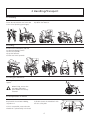
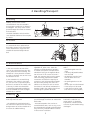
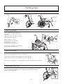
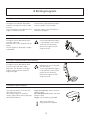
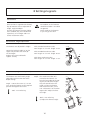
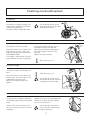
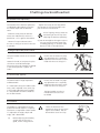
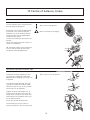
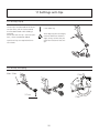
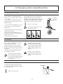
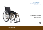
Next Comfort Manual English 74730H2015-03-16 Contents Heading Page 1. General...............................................................................................3 2. Handling/Transport...............................................................................4-5 3. Product Description..............................................................................6 4. Model ...............................................................................................7 5. Accessories/Options.............................................................................8-10 6. Quick guide.........................................................................................11-12 Settings 7. Seat........................................................................................13-14 8. Legrests..................................................................................15-16 9. Backrest /Headrest...................................................................17-18 10. Centre of balance/Brake..........................................................19 11. Anti-tip adjustments................................................................20 12. Changing castors/Handrims.....................................................21 13. Driving technique/Manoeuvring..............................................22-25 14. Assembly instructions Accessories........................................................26-29 15. Care and maintenance.........................................................................30-31 16. 17. 18. Tests and Guarantees...........................................................................32 Alternative seat heights/Angles............................................................33 Weights and dimensions/Standard model.............................................34-35 2 1 General The manual must be read thoroughly to avoid damage when handling and using the Next Comfort chair. (!) Anti-tips is a warning triangle to indicate that special care should be taken. provides advice and tips worth considering. come as standard. These prevent the wheelchair from tipping backwards. We recommend all users to use the anti-tip devices, unless you are an experienced user with absolute control over your wheelchair. Next Comfort is a manual, cross-folded, tiltable wheelchair with multiple functions that is intended for use both outdoors and indoors. The seat is adjustable in height and depth and is infinitely adjustable in angle. The backrest is adjustable in height, angle and contour. The footrests are adjustable in height, angle and depth. Next Comfort can be supplemented and adjusted if needs change. A large range of options and accessories are available: Various types of seats and backrests, headrests, brakes and legrests, fixing points for transport in mobility service buses etc. Next Comfort has the best prerequisites to create comfort, functionality and good manoeuvrability. Crash test Etac’s wheelchairs are tested and approved in accordance with ISO 7176-19. This ISO standard specifies requirements for the design of the wheelchair’s restraining points, how the wheelchair and the user are secured in the vehicle, and also describe how tests should be carried out and how the test results should be interpreted. Etac’s wheelchairs are crash tested at the Technical Research Institute of Sweden. The test was performed with normal settings on the wheelchair and with the transport attachment accessory (see manual). An UNWIN_WWR/ATF/K/R restraining device and an UNWIN_WWR/HD/ATF/K/R 3-point belt were used in the test. Etac’s positioning belt, heel straps and headrest should be used when travelling in vehicles. Seat widths: Seat depth: Max. user weight: From 35 cm to 50 cm. Short frame 42 cm. Long frame 48 cm. 135 kg. Service life: The product is tested and fulfils the demands stated in EN 12183. The main product’s durability and lifetime is at least five years when used in accordance with intended use, the safety instructions, the reconditioning manual and instructions for use in the user manual. The main product consists of the chassis for seat and back support. Additional parts/accessories are handled in accordance with the manual and reconditioning manual. The actual lifetime can vary, depending on how much and how intensively the product is being used, but a maximum of 10 years. Thereafter the product must be decommissioned. The following methods of surface treatment have been used: Lacquered surfaces=Polyester powder coating, Non-lacquered aluminium parts=Anodized coating, Non-lacquered steel surfaces=Galvanized The tool kit contains: 1 Allen key 5 mm 1 Ring spanner 24 mm Settable= Adjusted using tools Adjustable= Adjusted without tools 3 2 Handling/Transport 2:1 Unfolding Press down on one side of the seat frame (do not hold the seat frame due to the risk of pinching your fingers). Fit seat, back pad and seat cushion. Flip down the footrests. ”Click” 2:2 Folding Remove seat cushion/back pad and any bow handle/cross brace. Lift the seat upwards. Flip up the footrests. Pull the seat frame upwards. 2:3 Lifting the wheelchair Lift using the push handles and legrests. Before lifting, ensure that the height adjustable push handles are securely fastened. 2:4 Transportation in vehicles Private car/taxi: The wheelchair should be placed in the car boot. Folding, see point 2:2. seat, so that it cannot overturn or roll. If possible secure the wheelchair with the car’s safety belt. If this is not possible, ensure that the wheelchair is placed safely in the back 4 2 Handling/Transport 2:5 Securing Mobility service bus or similar: The wheelchair must be secured in the transport attachment as shown in the diagram. The straps must not be passed through the wheels or around the back tubes. The back should be vertical and the seat should be horizontal for transport by vehicle. 2:6 Seat belt It is essential for the 3-point belt to be fitted as shown in the illustrations. There should not be any part of the wheelchair between body and seat belt. 2:7 Recommendations Etac recommends in the following order: 1) The user transfers to one of the seats in the vehicle and uses the vehicle’s 3-point belt while travelling. The wheelchair is then placed in the boot or safely in the back seat so that it cannot overturn or roll. 2) The wheelchair is secured facing forwards in the vehicle as per point 2:5, the user uses a separate 3-point belt that is secured in the vehicle. This is the way in which the wheelchair is tested and approved according to the ISO-standard for crash testing of wheelchairs in vehicles. 3) According to directive 2001/85/EC, appendix VII, point 3.8.3. there are specially marked wheelchair locations in vehicles that permit transport with a wheelchair facing in the opposite direction of travel. If this means of travel is used, the user/care giver must be aware while travelling, prepared for sudden movements and have the capacity to maintain a safe sitting position throughout the entire journey. The user’s disabilities must not be of such an extent that he/she is not able to hold onto the handles fitted in the vehicle when there are changes of speed or direction. In conjunction with points 2 and 3: - a positioning belt must be used - a correctly adjusted headrest must be used - the backrest must be level with or above the user’s shoulders - the parking brake must be used - the anti-tips must be lowered - a heel strap must be used - a cross brace must be used (not with ECS back support) - The restraining device must not be passed through the wheels or around the back tubes. If the wheelchair has been involved in a collision in a motor vehicle, it should be inspected at a Technical Aids Centre or by Etac before being used again. 2:8 Warning - During transport the headrest and heel strap must be used. - The wheelchair’s positioning belt is not sufficient to prevent the user from being thrown out of the wheelchair in the event of sudden braking. - Accessories/options that can be removed without tools, such as trays, must be removed and secured or placed where they cannot fly around inside the vehicle in the event of a collision. 5 3 Product description Next Comfort is constructed around a seat unit and a propulsion unit. Height adjustment is possible without changing the rear wheels, front forks or castor wheels. The seat height is not affected by the castor size, and the front fork attachments need never be angle-adjusted. Nor do the brakes need to be adjusted when the rear wheel position is changed. 24 2 1 20 21 3 19 15 14 18 16 17 22 10 4 13 12 7 5 6 9 Item Description 23 11 8 1 Push handles 2 Back pad 3 Seat upholstery including cushion 4Brake 5Footrest 6 Footrest locking knob 7Legrest 8 Castor wheel 9 Front fork 10 Side block incl. front fork attachment 11 Protective stopper 12 Shock absorber 6 Item Description 13Brace 14 Side frame 15 Armrest, lockable 16 Armrest attachment 17 Quick release hub 18Handrim 19 Rear wheel 20 Back tube 21 Locking knob, push handles 22Anti-tips 23 Heel strap 24Headrest 4 Model Standard model *Seat adjustable in angle/tilt -3° (±1°) +20° (±2°) Seat height 44 cm, adjustable by 6 cm without changing rear wheels, fork or castor wheels Seat depth, settable Hard seat / flat seat Alternative model (options) Seat, settable in height Front seat height 40-49 cm, with seat angle +3° Cloth upholstery with adjustable seat depth 6 cm Castor wheels: 6" 150 mm solid Castor wheels: 5" 125 mm solid, 7" 175 mm semisolid (7" only with 24” rear wheel and not in seat height D, short frame) 24" rear wheel, quick release hub 20" or 22" rear wheels, quick release hubs 1" high pressure tyre (with inner tube) 22": 1" high-pressure tyres 20": 1 x 3/8" low-pressure tyre Solid tyres: 20", 22" and 24" Solid inner tubes 20”, 22” and 24” Handrims: 22" and 24": stainless or plastic-coated Handrims: 20": stainless Handrims: Aluminium Camber angle 2° Backrest settable in height, angle and shape Backrest height set at 59 cm continuously settable 59-69 cm Backrest angle set at +2° (=92° between backrest and seat) Backrest settable in height, angle and shape Backrest height 48 cm, settable between 48-62 cm Backrest upholstery adjustable with cover continuously settable 30-45 cm (incl. cross brace) Backrest upholstery high adjustable with cover continuously settable 38-55 cm (incl. cross brace) Backrest angle continuously settable between -5° - +15° Height adjustable push handles, detachable Steering bar height adjustable, detachable, fixed or adjustable angle Legrests - lockable, swing-away, detachable Legrests - lockable, swing-away, detachable Legrests with standard knee angle Legrest with narrow or short/narrow angle Legrests, continuously angle-variable Legrests, angle-variable self-extending Amputee legrest Flip-up footrests, foldable, adjustable in height, settable in depth and angle Heel strap Footrests as standard with extended attachment tube (+10 cm height adjustment) One-piece footrest. Headrest Several options are available Armrest, lockable, height-adjustable 38 cm Armrests 25 cm long Anti-tips, flip-up, settable in height Anti-tips, telescopic, flip-up Dimensions and tolerance +/- 2%. *In rear wheel position 1, seat height D, +14° (±2°) 7 5 Options 8: 6 Sittsdjup Backrest upholstery adjustable with cover, continuously height settable 30-45 cm, fitted with cross brace Backrest upholstery high adjustable with cover, continuously height settable 45-55 cm, fitted with cross brace Bow handle height adjustable, fixed or adjustable angle, detachable Seat upholstery with adjustable seat depth 6 cm Single hand brake for installation on right or left side Legrest with narrow knee angle Legrest with narrow/short knee angle Angle adjustable legrest with flip-up calf support from 40 cm seat width Angle adjustable legrest with calf support adjustable in height, depth and angle Angle-adjustable legrest self-extending Amputee legrest settable in height, adjustable in length, angle and sideways. Plush or black Dartex detachable cover. Can be combined with an amputation weight. One-piece footrest height adjustable, flip-up Handrims stainless or plastic coated Settable= Adjusted using tools. Adjustable= Adjusted without tools 8 5 Options Headrest cushion with siderest or shaped cushion. Rod with 45°, 90° angle or swan neck. Anti-tips telescopic, flip-up, settable in height, adjustable in length and angle 5 Accessories Armrest lockable, height-adjustable 25 cm long, solid top, black Armrest lockable, height-adjustable 38 cm long, solid top, black Armrest low lockable, height-adjustable 25 or 38 cm long, solid top, black Armrest cover detachable, 25 or 38 cm long padded or gel, dark grey plush or black Dartex Armrest cushion wide and soft, fits onto armrest, 8x40 cm Armrest cushion Hemi swing-away for mounting on long armrests Tray transparent, fits onto long armrest Hemiplegia tray t ransparent, for positioning of hemiplegic arm. Can be fitted onto both short and long armrests. Anti-slip device for the Hemi Tray Seat cushion d ark grey plush and black velour, 56 cm, cut according to seat depth set, washable 9 5 Accessories Calf strap detachable, black nylon, settable in length Padding for calf strap Extended footrest fits onto the existing footrest Positioning belt two pieces, with snap-lock, fixing points on the wheelchair frame Cross brace with snap lock Back wedge length 15 and 30 cm, attached with Velcro Trunk support settable in depth and angle, black Dartex, foldable, incl. attachment Cane holder two parts, one of which is an elasticated section that is fastened around the cane. Spoke guard with grey or yellow print Transport attachment Drum brake Max +20° (±2°) Min 0° Angle limitation +20° - 0° Tool kit 5 mm Allen key, 24 mm ring spanner Settable= Adjusted using tools. Adjustable= Adjusted without tools 10 6 Quick guide This section is intended for anyone with experience of adjusting wheelchairs who only requires brief instructions. More detailed instructions can be found after the Quick Guide. 6:1 Seat height The seat height is settable by 5 cm without changing rear wheels, front forks or castors. 1. 3. 1)Press up the tilt handle into the tightened position. 2)Secure the handle with the Velcro strap that is attached to the tool bag. 3) Undo the nuts holding each side bar. Pull out the bar by holding it in the middle (3). Select new height position and secure the side bars. 2. Tools: 24 mm ring spanner For further seat height adjustments, see section 7, Settings seat. 6:2 Seat angle +20° (±2°) -3° (±1°) 11 6 Quick guide 6:3 Backrest height The backrest is infinitely settable. Tools: Allen key 5 mm Start by removing the back pad. Then loosen the screws on the inside of the back tubes by 2-3 turns. Adjust the height by pulling/pushing the backrest upwards/downwards. 6:4 Backrest angle The backrest angle is infinitely settable. Tools: Allen key 5 mm Loosen the screws on the inside of the backrest joints. The brake cables can be angled down for better access. Adjust to the required angle and tighten. Risk of tipping! Always check the position of the anti-tips after changing the backrest angle. 12 7 Settings seat 7:1 Seat height The seat height is settable without changing rear wheels, front forks or castors. For further height adjustment the rear wheel and front fork have to be changed. The castor wheels do not affect the seat height, and are selected solely based on application. 7:2 Adjustment of seat height using existing rear wheels and front forks Remove the rear wheels by depressing the button in the centre of the hub while pulling the wheel out. (fig. 1). Press up the tilt handle into the tightened position (fig. 2). Secure the handle with the Velcro strap that is attached to the tool bag (fig. 3). 1. Undo the nuts holding the side bar. Pull out the bar by grasping it in the middle (fig. 4). Select new height position and secure the side bar. (fig. 5). Repeat steps 2-5 on the other side. Tools: 24 mm ring spanner 2. 3. 4. 5. 7:3 For further adjustment of seat height For further adjustment of the seat height, rear wheels and front forks must be changed. Each rear wheel size has a specific accompanying fork size. See table in section 17, Alternative seat heights/angles. Remove the rear wheels. Changing front fork: Begin by undoing the castor wheels and attaching them to the new forks (see section 12, Changing castor wheel/handrim). Remove the cover cap from the front fork assembly so that the locking nut is accessible. Undo it and pull out the front fork. Take the washer from around the fork axle and put it on the new fork (the bevelled side (A) towards the fork). Insert the new fork into the attachment. It is also important to ensure that the washers in the attachment (under the retaining nut) are placed in the right order, with the spring washer on top. Tighten the retaining nut until it cannot be turned any more. Loosen ½-1 turn. The spring washer then has the correct tension and reduces the risk of the castor starting to ”wobble”. Tools: 5 mm Allen key, 19 mm socket spanner. Do not change castor wheels in order to alter the seat height or the seat angle (see section 12). The bar must always be in the horizontal position. 13 Ball bearings A 7 Settings seat 7:4 Seat angle +20° (±2°) -3° (±1°) 7:5 Adjusting seat depth The seat depth can be varied 0-6 cm by moving the seat plate backwards/ forwards. Loosen the screws (A) and move to the required position. Tighten. Short frame: 35 - 41 cm (measured from the back tube). Long frame: 41 - 47 cm (measured from the back tube). A The functional seat depth is affected by the position of the back pad. 7:5 Adjusting seat depth The seat depth can be adjusted 0-6 cm at the front by lifting the front seat upholstery and sliding it backwards or forwards (A). Short frame: 36 - 42 cm (Measured from the back tube) (B) Long frame: 42 - 48 cm (Measured from the back tube) (B) C The functional seat depth (C) is affected by the position of the backrest upholstery. B 7:7 Adjusting the cable casing Each time you make an adjustment that affects the tilting function, for instance fixing the cable cover with plastic ties, check that the cable by the locking piston is not stretched tight. 14 A 8 Settings legrests 8:1 Legrests The legrests are lockable, detachable and can be swung to the side or under the seat. They are available in two different knee angles; standard and narrow. A continuously angle adjustable legrest with calf support is also available. Amputee legrests are also available as alternatives to legrests. 8:2 Legrest, continuously angle-adjustable The legrest can be adapted for either the left or right side. Directions for use are supplied with the legrest. The calf support is adjustable in height and foldable. As the angle adjustable legrest is not lockable, it must not be used to lift the wheelchair. Remove the legrests and lift using the frame. 8:3 Legrest, angle-adjustable, self-extending The legrest can be adapted for either the left or right side and is angle- adjustable. The footrests are in right and left versions and are settable in height and angle. Directions for use are supplied with the legrest. As the angle adjustable legrest is not lockable, it must not be used to lift the wheelchair. Remove the legrests and lift using the frame. 8:4 Amputee legrest (option) The amputee legrest fits the left and right sides of the chair. The amputee legrest is settable in height, angle and can also be adjusted forward and sideways. Angle and sideways: loosen the lever under the plate. Forwards/backwards: loosen the knob under the plate. Height: use the Allen key provided. Tools: 4 mm Allen key (supplied with the support) 15 8 Settings legrests 8:5 Footrests For outdoor use the footrests should be raised 4-5 cm above the ground. Never stand on the footrests as you may tip the chair. Next Comfort is supplied with divided, flip-up footrests that are adjustable in height, angle and depth. To make the footrests lower or higher than standard, they are available with respectively 10 cm longer and 8 cm shorter attachment tubes. 8:6 Footrests, height adjustment The footrests are adjustable in height. Loosen the locking handle (A) on the legrest fully. Remove the screw (B). Set the height. Replace the screw and handle. Tighten securely. With standard attachment tube: Max. length: 51 cm. Min. length: 33 cm. With extended attachment tube: Max. length: 61 cm. Min. length: 46 cm. With short attachment tube: Max. length: 41 cm. Min. length: 31 cm. B A 8:7 Footrests, angle and depth adjustment The footrests are continuously angleadjustable and have two alternative depth settings. Angle: Loosen the screws (C) 1/2-3/4 turn. Angle the footrest to the required position and tighten the screws. Tools: 5 mm Allen key Depth: The attachment tube (D) is secured to the footrest 1/3 from the front edge. By changing the left side for the right they will extend further forwards. Pull out the footrest and attachment tube, turn it 180° and secure it to the other legrest tube. Adjust the footrest angle. Tools: 5 mm Allen key (to adjust the footrest angle) 16 C D 9 Settings backrest/headrest 9:1 Backrest The backrest is settable in height and angle and has adjustable back pad or settable cloth upholstery. The push handle is height adjustable. Risk of tipping! Always check the position of the anti-tips after adjusting the backrest. 9:2 Backrest height The backrest is infinitely settable. Loosen the screws on the inside of the back tubes by 2-3 turns. Adjust the height by pulling/pushing the backrest upwards/downwards. If the height is adjusted with the back pad removed or the chair is equipped with settable cloth upholstery, ensure that both back tubes are adjusted equally by checking the height against the straight edge on the rear of the backrest. Tighten the screws securely. Tools: Allen key 5 mm 9:3 Backrest angle The backrest angle is continuously settable. Loosen the screw on the inside of the backrest joint. The brake cable can be angled down for better access. Adjust to the required angle and tighten. Tools: Allen key 5 mm Risk of tipping! Always check the position of the anti-tips after changing the backrest angle. 9:4 Back pad (ECS) The contour of the backrest upholstery is individually adjustable by using Velcro straps. Loosen all the straps and ensure that the user is sitting as far back in the seat as possible. Tighten the straps so that they follow the contours of the back and give support for the curve of the back. Risk of tipping! Always check the anti-tips after adjusting the backrest upholstery. 17 9 Settings backrest/headrest 9:5 Settable cloth upholstery The contour of the backrest upholstery is individually adjustable by using the five Velcro straps and the backrest cover. - Allow the cover plenty of room between seat and backrest, so that it is possible to ”sit in” against the backrest. - Loosen all straps and ensure that the user is sitting as far back in the seat as possible. - Tighten the straps so that they follow the contours of the back and give support to the curve of the back. Risk of tipping: Always check the positioning of the anti-tips after adjusting the backrest upholstery. (!) D o not overtighten the upper straps as this can prevent the cross-brace from unfolding properly, i.e. the back tubes do not sit flush in the side-frames. 9:6 Height adjustable push handles The push handles can be set at intervals of 2 cm. Loosen the knob (A) and press the plastic washer. Install desired height. Ensure that the push handles are locked in the correct position. Tighten the knobs. Ensure that the knobs are properly tightened. This is especially important when the chair is to be lifted with the user sitting in it. 9:7 Bow handle (option) The bow handle is height adjustable and detachable. It is mounted in the push handle attachment, and is adjusted in the same way as the height-adjustable push handles. It is also possible to mount a headrest on the bow handle. Ensure that the knobs are properly tightened. This is especially important when the chair is to be lifted with the user sitting in it. The bow handle must be removed before the chair can be folded. 9:8 Headrest The headrest is mounted on the back pad or bow handle (option). A separate attachment is required for a bow handle. It is adjustable in height, depth and angle, and is detachable. Check the balance of the wheelchair when the user leans against the headrest. We recommend the use of anti-tips. (!)Before adjusting the headrest, ensure that the user has a good, secure sitting posture. 18 10 Centre of balance, brake 10:1 Rear wheels, balance adjustment The rear wheels have 2 alternative positions for balance adjustment. Remove the rear wheels by depressing the button in the centre of the hub. Undo the nut on the inside of the bar. The brake cable can be angled downwards for better access. Pull out the attachment and select new position. Secure the attachment with washers as shown in the diagram. Tools: 24 mm ring spanner Bear in mind the risk of tipping. NB: The lower section of the attachment must fit into the notch on the chassis. The brakes need no readjustment. 10:2 Brake, adjustment of brake cable The brakes function regardless of the tyre pressure, and do not need to be adjusted when changing rear wheel size or position. Tools: 8 and 10 mm U-spanner. A If the brakes need adjusting, do so by altering the length of the brake cable: Loosen the top nut (A), so that the bottom one (B) can be adjusted. B C B Tighten or loosen the bottom nut, so that the brake pin does not touch the wheel when turning. At the same time, keep hold of the hexagonal terminal (C) on the cable housing. Check the function of the brakes. Screw clockwise: The pin moves in. Screw anticlockwise: The pin moves out. 19 11 Settings anti-tips 11:1 Anti-tips, flip-up The anti-tips are mounted on the tilters. To raise them, pull the sleeve around the tilter downwards while folding it upwards. Ensure that the anti-tips ”click into position”, when extended or folded. Special anti-tips are required with 20" rear wheels. 5 mm Allen key After adjusting the seat height, centre of balance or backrest angle, always ensure that you check the function of the antitips. 11:2 Anti-tip, telescoping Max. 5 Nm “Click” 3-7 cm “Click” 20 12 Changing castor wheels/handrims 12:1 Changing castor wheels Next Comfort can be equipped with 125 mm (5"), 150 mm (6") or 175 mm * (7") castors. Select a size to suit driving technique and environment, not to alter the seat height or angle. Each rear wheel size has a specific accompanying fork size. See table in section 17 (Alternative seat heights/angles). For higher and lower seat heights see non-standard combinations. Contact customer service. Tools: 5 mm Allen key * 175 mm is only suitable with 24" rear wheels (not in rear wheel position D, short frame). The bar must always be in the horizontal position. Remove existing castor wheel by unfastening screw and nut. Move the plastic components to the hole on the fork that is marked with the specific castor size. Secure the new castor wheel. 24"22" 20" 7" 6" 5" 6" 5" 6" 5" 12:2 Handrims Next Comfort is delivered as standard with aluminium handrims. The way in which the user is able to grip the handrims is influenced by the handrims material and its distance from the wheel. Stainless and plastic coated handrims are available as options. The plastic coated handrims give a better grip, but also increase friction. Violent braking can cause mild friction burns (e.g. blisters). Be aware that when passing through narrow spaces there is a risk of getting your fingers caught. There is also a risk of fingers getting caught in the spokes. If there is a risk of the user’s fingers getting caught in the spokes we recommend spoke guards. 12:3 Adjusting the distance of the handrim The distance between the wheel and the handrim can be adjusted by adding or removing spacers. Handrim Tools: 4 mm Allen key. Spacers 21 13 Driving technique, settings manoeuvring 13:1 Driving technique Weight distribution is the decisive factor when it comes to operating conditions. It is in part dependent upon the user’s weight, size and seating position and in part upon the position of the rear wheels longitudinally. The more weight that is placed over the rear wheels, the easier the wheelchair is to manoeuvre. The more weight over the castor wheels, the heavier the chair becomes to operate. Care giver: If the user is left alone in the wheelchair, ensure that the brakes are applied and that the anti-tip is swung down. Parking: Increase the overall support base of the wheelchair by reversing for about 10 cm, thereby ensuring the castor wheels swing forwards. 13:2 Ascending kerbs, higher thresholds Care giver, driving up forwards: • Ensure that the anti-tips are turned upwards. • Tilt the wheelchair, if necessary with help from a tilter, so that the castor wheels come up on the pavement. • Lift by the push handles to help the rear wheels up. Lower the anti-tips again. User, driving up backwards: This technique only works if there is a low kerb/threshold, relative to the installed height of the footrests. • Ensure that the anti-tips are turned upwards. • Reverse to the edge of the kerb/ threshold. • Take a firm hold of the handrims while at the same time leaning forwards. Care giver, driving up backwards: • Ensure that the anti-tips are turned upwards. • Reverse the chair to the edge of the kerb/threshold. • Tilt the wheelchair up, if necessary with help from the tilter, so that the castor wheels are in the air. • Pull the wheelchair upwards and backwards, ensuring that the castor wheels have cleared the edge before setting down the wheelchair on all four wheels. Lower the anti-tips again. Lower the anti-tips again. 22 13 Driving technique, settings manoeuvring 13:3 Descending kerbs User, driving down forwards: This technique is recommended only for experienced wheelchair users. • Ensure that the anti-tips are turned upwards. • Drive forward to the edge of the kerb. • Take a firm hold on the handrims and drive ”straight out” so that the wheelchair lands below the kerb on all four wheels simultaneously. Care giver, driving down forwards: • Ensure that the anti-tips are turned upwards. • Tilt the wheelchair, if necessary with help from a tilter, so that the castor wheels are in the air. • Drive carefully down the kerb and set down the castor wheels onto the ground again. User, driving down backwards: This technique is not recommended for differences in level of over 10 cm. • Ensure that the anti-tips are turned upwards. • Reverse to the edge of the kerb. • Reverse carefully down while at the same time leaning forwards. Care giver, driving down backwards: • Ensure that the anti-tips are turned upwards. • Reverse the wheelchair to the edge of the kerb. • Drive carefully down the kerb and reverse the wheelchair on the rear wheels until the castors have cleared the obstacle. • Set down the wheelchair on all four wheels. Lower the anti-tips again. Lower the anti-tips again. There is a greater risk of tipping during this manoeuvre. Lower the anti-tips again. Lower the anti-tips again. 23 13 Driving technique, settings manoeuvring 13:4 Driving technique, inclined surface The following constitutes important advice for driving up or downhill to avoid the risk of tipping. (!) Avoid turning round in the middle of a hill. Always drive as straight up/ down as possible. It is better to ask for help than to take a risk on your own. Uphill driving: Lean forwards to correct your centre of balance. Downhill driving: Lean against the backrest to correct your centre of balance. Control your speed using the handrims, not by means of the brakes! If you need to stop on a slope and apply the brakes, it can feel as if the brake levers have jammed when you try to release them again. Uphill slope: Push the handrim forward as you release the brake. Downhill slope: Brace your weight against the handrim as you release the brake. With a care giver: Push the wheelchair gently forward or brace your weight against it as the brakes are released. Experienced wheelchair users: ”Rock” your upper body as the brakes are released. 13:5 Negotiating stairs, up Always ask for help. Never travel on an escalator, even if there are care givers available. We always recommend using two carers for this transfer. One who walks behind and holds on to the push handle and one who walks in front and holds on to the frame (or in the legrests if these are lockable). With care giver, backwards: • Flip up the anti-tips and ensure that height adjustable push handles are properly tightened. • Reverse the wheelchair to the first step. • Tilt the chair onto its rear wheels, using the tilter if necessary. • Pull the wheelchair slowly upwards, one step at a time, keeping the wheelchair balanced on its rear wheels at all times. • When the last step has been cleared, continue backwards so that the castor wheels are over the ground before setting down the wheelchair onto all four wheels. Lower the anti-tips again after completed transfer. (!)The care givers should remember to use the strength in their legs and to keep their backs as straight as possible while lifting. 24 13 Driving technique, settings manoeuvring 13:6 Negotiating stairs, down Always ask for help. Never travel on an escalator, even if there are care givers available. We always recommend using two carers for this transfer. One who walks behind and holds on to the push handle and one who walks in front and holds on to the frame (or in the legrests if these are lockable). With care giver, forwards: • Flip up the anti-tips and ensure that height adjustable push handles are properly tightened. • • • Drive forwards to the first step and tilt the chair onto its rear wheels, if necessary using the tilter to help. Descend carefully one step at a time, keeping the wheelchair balanced on its rear wheels at all times. After the last step, set down the wheelchair on all four wheels. Be sure to turn the anti-tips back to the down position after completed transfer. (!)The care givers should remember to use the strength in their legs and to keep their backs as straight as possible while lifting. 13:7 Transferring into/out of the wheelchair The technique for transferring a user should be practised with trained personnel. All that is provided here is some important advice to consider in conjunction with transferring a user into or out of the wheelchair. With or without a care giver, sideways. Before transferring: • Position the wheelchair close to the new seat. • Reverse the wheelchair 5-10 cm so that the castors are turned fully forwards. • Apply the brakes, remove or swing up armrest/side guard and legrest on the side you intend to move across. With or without a care giver, from the front. Before transferring: • Position the wheelchair close to the new seat. • Reverse the wheelchair 5-10 cm so that the castors are turned forwards. • Apply the brakes and swing the legrests in under the seat. Never stand on the footrests as there is a risk of tipping! (!)The care givers should remember to use the strength in their legs and to keep their backs as straight as possible while lifting. 25 14 Assembly instructions accessories Assembly instructions are provided with all accessories when they are supplied by Etac. Instructions are also available on our website www.etac.com 14:1 Armrest, lockable and detachable, height adjustment The armrest comes in two versions, with short or long armrest guard. To remove the armrest, move the springmounted lever backwards, towards the armrest bracket, and lift up the armrest. Height adjustment: The screw/nut is used both to set the height of the armrest and secure the side guard: • Undo screw and nut. • Slide the side guard up or down to the desired height. • Secure the sideguard again. Tools: 5 mm Allen key. Never use the armrests to lift the wheelchair. 14:2 Padded cover, armrest The armrests can either be supplemented with, or ordered complete with, a padded or gel cover. They are manufactured in dark grey plush and are washable. (!)The padded cover makes the armrest 1.5-2 cm higher. 14:3 Armrest cushion Hemi Swing-away for mounting on long armrests. 14:4 Tray The tray is made of polycarbonate, with a recess to fit round the body. It is available in a range of sizes depending on the wheelchair’s width. It is mounted on the long armrests using Velcro straps. The height is adjusted along with the armrests. Tools: 5 mm Allen key (for adjusting the height of the armrests) 26 14 Assembly instructions accessories 14:5 Hemi Tray The Hemi Tray is attached to the accompanying padded armrest covers by means of the Velcro tape. These are supplied with Velcro on the upper side. The height is adjusted with the armrest. The tray can be fitted onto short or long armrests. 14:6 Anti-slip device for the Hemi tray 14:7 Calf strap The calf strap is in two parts and can be separated when the legrests are swung out to the sides. The length can be adjusted. It can be mounted at any height with self-adhesive Velcro around the legrests. (!)Adjust the length so that the foot is placed in the centre of the footrest. Before transferring into/out of the wheelchair separate the calf strap and flip up the footrests. 14:8 Padding for calf strap 14:9 Extended footrest Extended footrests fit onto the existing footrests. Hole instructions for fitting the screw are on the bottom of the footrest. Make the hole by carefully knocking the screw through the plate, e.g. with a hammer. Tools: 3 mm Allen key 27 14 Assembly instructions accessories 14:10 Positioning belt The belt is to be used only for positioning in the wheelchair. It must not be used as a substitute for a car safety belt. The positioning belt is in two parts, is adjustable in length and has a snaplock. It can be fitted to the back joints or in the holder on the side of the frame. (!) Ensure that the user does not slide forwards in the seat as this can lead to the belt impairing the supply of blood to the hip/ waist area. 14:11 Cross brace, backrest A cross brace can be fitted to the backrest for extra stability. It is recommended for high and/or rearleaning backrests. The cross brace is fixed to the push handles and can easily be removed using the snap lock. The cross brace must be uncoupled if the chair is to be folded. 14:12 Cane holder, mounting • • Loosen the screws that hold the anti-tip bar. Fit the cane holder. Fit the screw and tighten. Thread the elastic strap ’double’ around the stick to make a loop. The tip of the stick may have to be removed to allow you to attach the elastic. • Place the stick in the holder and stretch the elastic loop over the push handle. Tools: 5 mm Allen key. Check the function of the antitips. 14:13 Spoke guards The spoke guards prevent your fingers from becoming entangled in the spokes and also give some protection against splashing. They come in three sizes, corresponding to our rear wheel dimensions. Fitted without tools using the plastic components supplied. 28 14 Assembly instructions accessories 14:14 Transport attachment 14:15 Drum brake 5 mm 29 15 Care and maintenance Upholstery, back pad and seat cushion (ECS) Remove any seat cushion and back pad according to point 2:2. Take off the upholstery and wash according to the washing instructions on the product. Settable cloth upholstery, backrest and seat The backrest upholstery is removed by undoing the push handle attachments. Then pull the upholstery upwards and wash according to the washing instructions on the product. The upholstery is made of two-ply polyester. The seat upholstery is fastened lengthways to the seat frame. The upholstery can easily be removed from the frame by unscrewing the end caps. Rear wheel/castor Tyre/inner tube:Check the tyre pressure (see side of tyre) and tread at least once a month. Wheel axles:Clean the wheel axles from hair and dirt as necessary. Spokes: Loose spokes can lead to wheel wobble. Consult a cycle dealer or your Technical Aids Centre if it is necessary to adjust the spokes. Ball bearings: Require no maintenance. Handrims:If a handrim should be damaged in such a way that it could lead to injury, it should be replaced. Brakes The braking effect is independent of the air pressure in the tyres. Encrusted dirt can have a negative effect on the brake mechanism. Check the functioning of the brakes once a month. In the event of adjustments, see section 10 Centre of balance/brake. Washing the frame It is important to keep the wheelchair clean, both for your own comfort and the longevity of the chair. It is equipped with drainage holes which ensures that it is easy to wash and dry. Clean the frame with a non-abrasive cleaning agent with a pH level between 5 and 9, or with a 70% disinfectant solution. Rinse and dry. Miscellaneous Etac will not be held responsible for damage or injury caused by use of non-original parts. If there is a fault in your wheelchair you should contact your dealer or Technical Aids Centre. Defective wheelchairs should not be used. (!) When necessary, lubricate moving parts/joints with bicycle oil or similar. If your chair needs reconditioning or repair, only original parts from Etac or components with equal quality, as specified in diagrams, should be used. 30 15 Care and maintenance Fault-finding chart Problem* Solution The wheelchair pulls to the side • • • • Inflate the tyres Rear wheel mountings are incorrectly fitted The user is distributing weight unevenly Release the tilt handle so that the bars are parallel The wheelchair feels ”heavy” to propel • • • • Inflate the tyres Rear wheel mountings are incorrectly fitted Clean the castor axles from hair and dirt Too much weight over the castors. Adjust the centre of balance The wheelchair feels ”heavy” to turn • • • Inflate the tyres Clean the castor axles from dirt Too much weight over the castors. Adjust the centre of balance Brakes not effective • Adjust the cable length, see section 10, Centre of balance/brake Rear wheels ”loose” • Adjust the length of the axle shaft Rear wheels hard to remove/replace • Clean and lubricate the quick release with cycle oil or similar Adjust the length of the axle shaft • The castors ”wobble” • • The front forks are not tight enough Too much weight over the castors. Adjust the centre of balance The wheelchair is hard to fold/unfold • • The backrest upholstery is too tight Clean and lubricate the cross-brace under the seat The wheelchair feels ”awkward” • • Inflate the tyres Check that screws, nuts and bolts are properly tightened The wheelchair stands on three wheels • Place the chair on a level surface, press in the tilt handle and release. Tilting not working • Adjust the length of the cable. (!) When necessary, lubricate moving parts/joints with bicycle oil or similar. * The user may experience several of these problems if the wheelchair is incorrectly adjusted or is being incorrectly used. 31 16 Tests and guarantees Next Comfort The Swedish Institute of Assistive Technology is tested and approved for use indoors and outside and is CE marked. Max. user weight is 135 kg. carries out both functional and technical tests. Testing methods conform to ISO standard 7176. CE marking:The product has passed all tests and met all criteria set by European standards for specific product groups. A proof that the product meets national and EU MDD (Medical Device Directive) requirements. Gives customers the chance to choose the right product by comparing test data. Guarantee: 5 year guarantee against material and manufacturing defects. For terms and conditions, see www.etac.com Special adaptations comprise everything that falls outside the instructions and settings in this Manual. Wheelchairs specially adapted by customers are not eligible for Etac’s CE marking. Etac’s guarantee no longer applies. If in the least doubt about the validity of adjustments, please contact Etac for advice. 32 17 Alternative seat heights/angles Seat height and angle are set according to section 7, ”Settings seat”. The castor wheels should not be replaced in order to change the height or angle of the seat, but should be selected solely with respect to driving technique and environment. Seat height with seat tilted back +3° (Etac Comfort Seating) 24" 22" 20" D 44 cm 42 cm 40 cm C 46.5 cm 44.5 cm 42.5 cm D C B B 49 cm 47 cm 45 cm Dimensions and tolerance +/- 2%. Dimensions from the ground to upper edge of the unpadded seat. Seat cushion 6 cm, unloaded. At 0° seat angle, the dimensions in the table are reduced by 2 cm. At -3° seat angle, the dimensions in the table are reduced by 4 cm. Seat height with seat tilted back +3° (settable cloth upholstery) 24" 22" 20" D 46 cm 44 cm 42 cm C 48.5 cm 46.5 cm 44.5 cm B 51 cm 49 cm 47 cm D C B Dimensions and tolerance +/- 2%. Dimensions from the ground to upper edge of the seat frame. Seat cushion 6 cm, unloaded. At 0° seat angle, the dimensions in the table are reduced by 2 cm. At -3° seat angle, the dimensions in the table are reduced by 4 cm. 24"22" ForkCastor wheel 24" 6"= 5"= 7"= 150x30 mm 125x30 mm 175x45 mm* ------------ 6"= 5"= 150x30 mm 125x30 mm ------------ 6"= 5"= 150x30 mm 125x30 mm 22" 20" *Can not be used on short frame chair with rear wheel in position D. 7" 6" 5" 20" 6" 5" 6" 5" Note the position in which each castor wheel is to be mounted. Incorrect mounting has a negative effect on operating conditions, as the front fork mountings are not adjustable on Next Comfort. The bar must be in the horizontal position. (!) Non-standard combinations are available: Several rear wheels and castors. Contact customer service. 33 18 Weights and dimensions, Etac Comfort Seating Type of chair Art. no. Seat depth Seat height Backrest height Total width Transport width Weight incl. rear wheel, legrest, anti-tips, ht. adj. push handle, seat and backrest 35 cm short 13202001 35-41 cm 44-49 cm 59-69 cm 54.5 cm 23 cm 24.0 kg 35 cm long 13202002 41-47 cm 44-49 cm 59-69 cm 54.5 cm 23 cm 25.2 kg 37.5 cm short 13202003 35-41 cm 44-49 cm 59-69 cm 57.0 cm 23 cm 24.0 kg 37.5 cm long 13202004 41-47 cm 44-49 cm 59-69 cm 57.0 cm 23 cm 25.2 kg 40 cm short 13202005 35-41 cm 44-49 cm 59-69 cm 59.5 cm 23 cm 24.4 kg 40 cm long 13202006 41-47 cm 44-49 cm 59-69 cm 59.5 cm 23 cm 25.6 kg 42.5 cm short 13202007 35-41 cm 44-49 cm 59-69 cm 62.0 cm 23 cm 24.4 kg 42.5 cm long 13202008 41-47 cm 44-49 cm 59-69 cm 62.0 cm 23 cm 25.6 kg 45 cm short 13202009 35-41 cm 44-49 cm 59-69 cm 64.5 cm 23 cm 25.0 kg 45 cm long 13202010 41-47 cm 44-49 cm 59-69 cm 64.5 cm 23 cm 26.3 kg 47.5 cm short 13202011 35-41 cm 44-49 cm 59-69 cm 67.0 cm 23 cm 25.0 kg 47.5 cm long 13202012 41-47 cm 44-49 cm 59-69 cm 67.0 cm 23 cm 26.3 kg 50 cm short 13202013 35-41 cm 44-49 cm 59-69 cm 69.5 cm 23 cm 25.3 kg 50 cm long 13202014 41-47 cm 44-49 cm 59-69 cm 69.5 cm 23 cm 26.5 kg Next Comfort: The dimensions and weights indicated apply to chairs with 24" rear wheels high pressure/aluminium handrims, legrests, anti-tips and height-adjustable push handles, seat and backrest cushion in PE. Height at front is measured from the top of the unpadded seat with the seat tipped +3° backwards, the height at the back is measured from the top of the unpadded seat and the seat depth is measured from the back tubes. Dimensions and tolerance +/- 2%. 34 18 Weights and dimensions, settable cloth upholstery Type of chair Art. no. Seat depth Seat height Backrest height Total width Transport width Weight incl. rear wheel, legrest, anti-tips, ht. adj. push handle, seat and backrest 35 cm short 13202001 35-41 cm 46-51 cm 31-45 cm 54.5 cm 23 cm 20.1 kg 35 cm long 13202002 41-47 cm 46-51 cm 31-45 cm 54.5 cm 23 cm 21.0 kg 37.5 cm short 13202003 35-41 cm 46-51 cm 31-45 cm 57.0 cm 23 cm 20.1 kg 37.5 cm long 13202004 41-47 cm 46-51 cm 31-45 cm 57.0 cm 23 cm 21.0 kg 40 cm short 13202005 35-41 cm 46-51 cm 31-45 cm 59.5 cm 23 cm 20.3 kg 40 cm long 13202006 41-47 cm 46-51 cm 31-45 cm 59.5 cm 23 cm 21.2 kg 42.5 cm short 13202007 35-41 cm 46-51 cm 31-45 cm 62.0 cm 23 cm 20.3 kg 42.5 cm long 13202008 41-47 cm 46-51 cm 31-45 cm 62.0 cm 23 cm 21.2 kg 45 cm short 13202009 35-41 cm 46-51 cm 31-45 cm 64.5 cm 23 cm 20.6 kg 45 cm long 13202010 41-47 cm 46-51 cm 31-45 cm 64.5 cm 23 cm 21.6 kg 47.5 cm short 13202011 35-41 cm 46-51 cm 31-45 cm 67.0 cm 23 cm 20.7 kg 47.5 cm long 13202012 41-47 cm 46-51 cm 31-45 cm 67.0 cm 23 cm 21.6 kg 50 cm short 13202013 35-41 cm 46-51 cm 31-45 cm 69.5 cm 23 cm 20.8 kg 50 cm long 13202014 41-47 cm 46-51 cm 31-45 cm 69.5 cm 23 cm 21.7 kg Next Comfort: The dimensions and weights indicated apply to chairs with 24" rear wheels, high pressure/aluminium handrims, legrests, anti-tips and height-adjustable push handles, seat and backrest cushion in two-ply polyester. Height at front is measured from the top of the seat frame with the seat tipped +3° backwards, the height at the back is measured from the top of the seat frame and the seat depth is measured from the back tubes. Dimensions and tolerance +/- 2%. 35 Etac Sverige AB Box 203 334 24 Anderstorp Sweden Tel 0371-58 73 00 Fax 0371-58 73 90 [email protected] www.etac.se Etac GmbH Bahnhofstraße 131, 45770 Marl, Germany Tel 02365-98710 Fax 02365-986115 [email protected] www.etac.de Etac AB (export) Box 203 334 24 Anderstorp Sweden Tel 46 371-58 73 30 Fax 46 371-58 73 90 [email protected] www.etac.com Etac Holland BV Fluorietweg 16a, 1812RR Alkmaar, Nederland Tel +31 72 547 04 39 Fax +31 72 547 13 05 [email protected] www.etac.com Etac AS Pb 249, 1501 Moss, Norway Tel 815 69 469 Fax 69 27 09 11 [email protected] www.etac.no Etac UK Limited 29 Murrell Green Business Park London Road, Hook, Hampshire RG27 9GR, United Kingdom Tel 01256 767 181 Fax 01256 768 887 [email protected] www.etac.com Etac A/S Egeskovvej 12 8700 Horsens Denmark Tel 79 68 58 33 Fax 75 68 58 40 [email protected] www.etac.dk Tel 0121 561 2222 Fax 0121 559 5437 [email protected] www.etac.com Snug Seat, Inc. 12801 E. Independence Boulevard P.O. Box 1739 Matthews, NC 28106, USA Tel 800 336 7684 Fax 704 882 0751 [email protected] www.etac.com R82 UK Limited. Unit D4A, Coombswood Business Park East Coombswood Way, Halesowen West Midlands B62 8BH United Kingdom Etac Supply Center AB Långgatan 12 SE-334 24 Anderstorp 7 320451 307484 74730