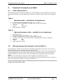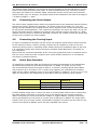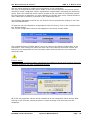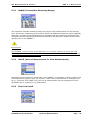
1
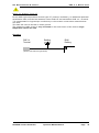
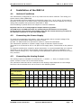
Operation Manual RHEONIK Coriolis Flowmeter RHE 14 RHM .. NT, ETx, HT RHEONIK the Coriolis Flowmeter experts REV. 2.3 March 2012 GE Measurement & Control reserves the right to make changes without notice at any time G E M ea su r em ent & Cont ro l RE V . 2 .3 M ar ch 2 0 1 2 TABLE OF CONTENTS Page Important safety instructions for operating Coriolis Flowmeters 4 Manufacturer’s Liability 5 Typical Applications and Benefits 5 Installation Instructions (in brief) 6 1. 2. General Description of System 1.1. The Flow Measurement System 7 1.2. Dimensions of Transmitter Casing RHE 14 8 1.3. Dimensions of Sensor RHM 8 Assembly and Installation 2.1. Installation Instructions for measuring Sensor RHM 2.1.1. Heating / Filling of a Sensor (Flowmeter) 2.2. Installation Instructions for Transmitter RHE 14 3. 4. 5. 9 12 13 2.2.1. Mechanical Installation 13 2.2.2. Description of the RHE 14 Assembly 15 Electrical Connection of RHM 3.1. Cable Specifications 16 3.2. Wiring between the flowmeter and the RHE 14 16 Installation of RHE 14 4.1. Ambient Conditions 19 4.2. Connecting the Power Supply 19 4.3. Connecting the Analog Output 19 4.4. Connecting the Pulse Output 20 4.5. Connecting the Zeroing Input 20 4.6. Serial Data Interface 20 Initial and Further Operation of Transmitter 5.1. Device Status Displays 22 5.2. Zeroing 22 5.3. Transmitter Configuration using the Serial Interface 22 5.3.1. RANGE (Transmitter Measuring Range) 26 5.3.2. UNITS (Units of Measurement for Flow Measurement) 26 5.3.3. Flow- Low Cutoff 26 5.3.4. Measurement Value Damping 27 5.3.5. Span Analog Output 27 5.3.6. Calibration Values for Coriolis Flowmeter 27 . RHEONIK Coriolis Flowmeter Operation Manual RHE 14 Page 2 G E M ea su r em ent & Cont ro l RE V . 2 .3 M ar ch 2 0 1 2 TABLE OF CONTENTS Page 5.3.7. Temperature Coefficient of Sensor Measuring Tube Material 28 5.3.8. Reading and Writing Sensor Serial Number 28 5.3.9. Reading and Writing Transmitter Serial Number 28 5.3.10. Changing the Polling Address 29 5.3.11. Transformer Self Test and Restart 29 5.4. Diagnosis of Internal Measurement Values 5.4.1. Drive Gain in % 30 5.4.2. Phase Counts 30 5.4.3. Zero Counts 30 5.4.4. Temperature ADC 30 5.4.5. Diagnosis of Analog Output (4-20 mA) 31 5.4.6. Resetting the Internal Counter (Quantity and Run-time Hours) 32 5.4.7. Zero Calibrating the Measuring Device 32 5.5. Configuration of the Pulse Output 5.5.1. 6. 30 32 DIP switches Location and Function 33 5.6. Jumper location and function on board M588 33 Troubleshooting 6.1. Error Status of Outputs 34 6.1.1. Pulse Output 34 6.1.2. Current Output 34 6.2. Notes on Troubleshooting 34 6.2.1. Case 1: The red ERROR LED is brightly on and the green SENSOR LED is off 34 6.2.2. Case 2: The green SENSOR LED flickers intermittently 35 6.2.3. Case 3: The red ERROR LED flickers or is on 35 6.2.4. Case 4: The analog output consistently supplies 20 mA 35 6.2.5. Case 5: The analog output consistently supplies 4 mA 35 6.2.6. Case 6: The analog output consistently supplies 4 mA 36 6.3. Important notes on repairs 36 A P P E N D I C E S: Installation Plan RHE 14 to RHM xx Installation Plan RHE 14 to RHE 15 (Profibus Adapter) Installation Plan RHE 14 to EZB 14 (Zener Barrier) Installation Plan RHE xx to RHM xx (free cable ends) EC Certificate of Conformity . RHEONIK Coriolis Flowmeter Operation Manual RHE 14 Page 3 G E M ea su r em ent & Cont ro l RE V . 2 .3 M ar ch 2 0 1 2 Imp o rta n t sa f et y i n s tru cti on s f o r op e rati n g C o ri ol i s Fl owm e t e r s Please ensure that the following safety guidelines are observed at all times The flowmeters are made for a variety of applications and in compliance with international standards. The operating conditions for the appliance are stated on the serial number plate and must be observed at all times. Where heated flowmeters are concerned, sufficient thermal insulation should be provided to ensure that the entire flowmeter is always kept at the operating temperature. Please ensure that no rapid changes in the measuring instrument temperature are caused by the measuring medium and observe the instructions given in this manual. The maximum permissible pipeline pressure for the flowmeter can be found on the serial number plate. When using piston pumps, always remember that no pressure peaks should be allowed to emerge which are above the maximum permissible pressure level. Prior to delivery, the measuring tubes are subjected to an overpressure test which is performed at 1.5 times the permissible operating pressure. We wish to point out that the abrasive medium may reduce the wall thickness of the measuring tubes and consequently lower the maximum operating pressure. The construction material that comes into contact with the medium can be found on the serial number plate. The manufacturer assumes no responsibility for the corrosion resistance of the measuring instrument with regard to the medium to be measured. Should the stability of the material that has been moistened by the medium be in doubt, we recommend that you check the wall thickness of the measuring tubes from time to time. GE assumes no liability for the loss of production and/or consequential damage unless this has been expressly agreed upon. Flowmeters for liquid foodstuffs and luxury foods or for pharmaceutical usage must be completely scavenged before being used. Man u fa ctu r e r ’s Li abi li ty Given the warranties and liabilities accepted by the manufacturer, please note that the measuring instruments may not be utilized in life-preserving systems used in medical applications, or in motor vehicles, aircraft, watercraft or in the mining industry. In addition, the manufacturer accepts no liability for damage resulting from the improper or non-compliant usage of the appliance. Liability for consequential damage or loss of production will solely be accepted if the customer expressly requires such liability or if it has been expressly agreed in the sales contract. . RHEONIK Coriolis Flowmeter Operation Manual RHE 14 Page 4 G E M ea su r em ent & Cont ro l RE V . 2 .3 M ar ch 2 0 1 2 Typical Applications and Benefits For more than 20 years now, RHEONIK Coriolis Flowmeters have been used by industry to determine the volume of such liquids and gases as: Acid, lye, alcohol, hydrocarbons Bitumen, fats Oils (mineral oil; vegetable oil; synthetic oil) Foodstuffs (vegetable oil; beer; liquid yeast; liquid sugar; chocolate; soup; sauces) Beverages, flavouring, liquid carbon dioxide Lacquers, paint, filling compounds, rubber products Fuel (methanol, diesel, petrol, kerosene, methane gas, liquid hydrogen) Coolant, hydraulic oil, brake fluid Deionized (non-conductive) water Animal fodder additives (molasses, rape seed oil, flavouring) Pharmaceuticals Cosmetics (creams, scented oils, emulsions) Polyol, isocyanate, polyester, propellants (freon, pentane, etc.) Gas station products (natural gas, propylene, propane) Ultra-cold, liquid gases (hydrogen, nitrogen, oxygen, etc.) Slurry, suspensions (oil/water) The advantage of using this patented measuring principle is that it allows for direct mass flow measurement. Given the rapid reaction time, the appliances are suited to both batch dosing and flow control or monitoring. The measurement is taken regardless of the pressure, temperature, viscosity, conductivity or flow characteristics of the liquid. Due to its unique design, the flowmeter is durable enough not to wear down even after many years of operation and is also a low-maintenance product. Inside the liquid stream, there are no fittings or rotating parts that could block the flow and consequently lead to a very costly shutdown of the production facilities. Installing the flowmeter into the pipeline system is easy. No long tube runs in front of and behind the sensor need to be taken into account and the flowmeter can be mounted almost directly behind turbulence creating elbows or pipe diameter reducers without impairing the accuracy of the measurements. Measuring media with fibrous content or a high solid charge does not pose any real difficulty. If used in accordance with the instructions, it is, unlike positive-displacement counters, possible to do without expensive filters without actually damaging the flowmeter. Measurements can be taken by the flowmeter irrespective of the flow of the liquid. Sudden pressure peaks or water shocks in the pipeline will not damage the appliance. In such an instance, other purely mechanical measuring procedures are prone to impeller wheels overtorquing, axles breaking, or bearings becoming displaced, which all result in the measuring device becoming unusable or even blocking the flow of liquid. Rheonik appliances are calibrated at the manufacturer’s site on precision test benches and can be operated directly without the need for local adjustments. A calibration certificate is supplied with the appliance. . RHEONIK Coriolis Flowmeter Operation Manual RHE 14 Page 5 G E M ea su r em ent & Cont ro l RE V . 2 .3 M ar ch 2 0 1 2 Rheonik Installation Quick Guide RHE 14 This is a short form, please read also our Field Manual - Before beginning initial operation, please remove the shaft block (only applies to large sensors > RHM 30) and then firmly close the casing again. START - Installing the sensor: For liquids (1) with the product connections above and For gases (2) with the connections below. (1) Liquids - The appliance should be firmly fixed in place using the connections provided. - When installing, please avoid locations where heavy vibrations and electric fields occur. Installation of RHM XX RHM RHM - We recommend using at least one valve during the zeroing procedure (2) Gases HT- SENSORS (High Temperat ure): Screen t o ground connect ion MUSTBE done. An addit ional pot ent ial equalising cable is required (see Manual). yellow green 7 grey 8 P ic -u p co il 2 whit e 9 10 Driv e c oi l 2 P T 10 0 - 4 P T 10 0 s ig na l 1 + 5 P T 10 0 s up p ly + 6 P ic k-up c o il 1 + 7 P ic k-up c o il 1 - Pin 3 TX > RX Pin 2 16 GND 17 digital pulse out put - passive (open collector Imax.10mA) 18 digital pulse out put - act ive TTL (IOH max. -0,4mA; IOL max.8mA) 3 2 1 P ic k-up c o il 2 - 9 P ic k-up c o il 2 + 10 Cab le -Sh ie ld 11 11 P T 10 0 s ig na l 2 + 12 Usable wit h special transmit ter only. RX < TX 15 5 12 (Lc =0,9 mH/km, Cc =0,2 uF/km) 9 x female GND <> GND Pin 5 14 4 8 Connect ing t erminals 10, 11 and 12 are available for sensors from production year 2006 onwards. RS 232 connect ion t o Host -Comput er: 13 20 1 1 :1 2 1 :1 00 3 1 :1 00 0 4 1 :1 00 0 0 6 R12 K o ut pu t-di vi de r an d 4 /3 wire P T 10 0 1 :1 0 9 8 7 19 +5V GND (Ca s in g) fi lte r ext ern zeroing >0< 21 22 23 - 5 6 Driv e - 3 - orange Driv e + 2 + pink 4 P ic -u p co il 1 1 blue red 3 T emp e ra tu re Sen s or P T1 0 0 RHE 14 brown 2 Wiring of RHM XX-RHE 14 + - NT/ ETx - Sensors: please DO NOT connect ! 1 24 + Mas s Flow Meter Sens or RHM xx Driv e c oi l 1 ext ernal volt age max.28 VDC analog out put - act ive current : 4 - 20 mA, max. 400 Ohm - Please ensure that the wiring is carried out as per our drawing. Caution: Passive digital outputs are using a pull-up resistance. Please observe the maximum permissible current of 10mA (never connect terminal 17 directly to an external voltage). power supply: 8 - 28 VDC / <1 Watt (SELV) 5 1 :1 00 0 00 6 1 :1 00 0 00 0 3 -wire P T 10 0 7 o ff on 8 T he DIP -s witc h es a re f ac to ry p re s et a cc o rd in g th e ca li brat io n sh e et a nd a v ai la bl e af te r remo v in g th e de v ic e co v er. created : 20.12.2004 Date Drawn Appr. Wi rin g di agra m RHE 1 4 sta nda rd H.G.Rudolph U.Het trich Project Customer Draw. - Rev. Sheet E14W-E_v1 1/1 - Power up the operating voltage. - Fill the sensor densely with the product and, where possible, perfuse for several minutes at a high flow rate. - Caution: Avoid temperature shocks at all costs! (Please observe the specifications listed in the manual) Fill RHM XX densely - Check : No error message / indication at transmitter ? - The red LED denoting "ERROR" will be lit up contious and weakly if there is no error detected. The green LED "SENSOR" is permanently blinking in a fast takt, indicating there are no malfunctions. - Close the product valve. Two valves are recommended for small sensors (RHM 015 - 03). - Begin the zeroing procedure by pressing the "ZERO" button. The zero point will be determined within approx. 20 secs. Once this process has been completed, the yellow LED (direction of flow) with the "+/-" indicator should flash. Zeroing procedure - Check for stable zero display. Are there any error messages from the remote unit? - Open the valves and power up the pumps, etc. The Rheonik mass flowmeter is now ready to run. Begin Measuring - Always check the stability of the zero point after making any major changes Installation recommendations v2.0 created by : [email protected] Changes without notice . RHEONIK Coriolis Flowmeter Operation Manual RHE 14 Page 6 G E M ea su r em ent & Cont ro l RE V . 2 .3 M ar ch 2 0 1 2 1 General Description of System 1.1 The Flow Measurement System The flowmeter consists of a: Sensor, type RHM xx Transmitter, type RHE xx Connection cable Inside the flowmeter, there are precision tubes that are energized by an electromagnetic drive system, which itself is fed by the transmitter, to vibrate at their natural frequencies. When a liquid or gas flows through the vibrating tubes, it is subjected to additional deflection due to the degree of inertia that is generated. This deflection is recorded electronically by two velocity sensors and a high-precision electronic time delta. This measured quantity is proportional to the mass flow rate. A further conversion into physical units is done in a purely digital manner using a signal processor in the transmitter. At the same time, all of the appliance’s functions are constantly monitored. Any disruptions will be displayed immediately in the LED signal status on the RHE 14. The transmitter has a 4 to 20 mA analog output with programmable span, which is proportional either to the measured mass flow rate or the temperature; it also has a passive and active pulse output that supplies mass-proportional impulses; two status outputs (ERROR, Flow Direction +/-) which can be set up active or passive. For service or repair purposes, the transmitter and flow sensor can be replaced independently of each other. This significantly reduces the costs of spare parts for the installed flow sensor/transmitter. During the factory calibration, the mass flow sensor can be calibrated independently of the transmitter. Both the sensor-specific data and the configuration of the units and outputs required by the user are forwarded to the transmitter via the serial port which is supplied as standard and also the supplied configuration program "SensCom". To achieve this, the instrument does not need to be opened. All of the relevant data is buffered in a non-volatile semiconductor device (EEPROM). The function of some digital RHE 14 outputs is configurable by the user via jumper coding on the controller board M588. The selection is described in this manual and in the wiring plan. In the section "mechanical installation" is described how to remove the upper part of the RHE 14 housing to get access to the jumpers on the board M588. . RHEONIK Coriolis Flowmeter Operation Manual RHE 14 Page 7 G E M ea su r em ent & Cont ro l 1.2 RE V . 2 .3 M ar ch 2 0 1 2 Dimensions of Transmitter Casing 58 49 10 29 60 46 5 10,3 37 1 3 1 4 1 5 1 6 1 7 1 8 1 9 2 0 2 1 2 2 2 3 2 4 3x4.8 86 4xØ3.2 Pro tectio n Class IP20 Dim en sio n s acc. to DIN 43880 Sn ap -o n mo u n tin g o n to stan d ar d ized DIN r ails EN50022 Material fo r u p p er elem en t: PC Material fo r lo wer elemen t: PPO Tem p eratu re ran g e (R HE14): -40 b is +60°C 1 2 3 4 5 6 7 8 9 1 0 1 1 1 2 70 1.3 Dimensions of Sensor RHM xx The dimensions can be found in individual data sheets, irrespective of the application of the sensor. Data sheets or exact drawings for customized products can be obtained from the dealer or the manufacturer. . RHEONIK Coriolis Flowmeter Operation Manual RHE 14 Page 8 G E M ea su r em ent & Cont ro l RE V . 2 .3 M ar ch 2 0 1 2 2 Assembly and Installation 2.1 Installation Instructions for measuring Sensor RHM The direction of flow through the flowmeter is bi-directional. The pipeline next to the flowmeter should be rigidly mounted as closely as possible to the hydraulic connectors using pipe clamps. In general, we recommend an installation with two firm supports at the in- and outlet of the RHM flow sensor. The supports should have a distance not larger than 3 times the housing width Any unsecured pipe sections situated near the flowmeter that might be caused to vibrate should be definitely avoided at all costs. Due to the construction of the flowmeter and the digital measuring filter of the signal processor, it is possible to minimize the amount of interference caused by vibrations in the system. Nevertheless, heavy vibrations can result in the measuring accuracy being significantly impaired and, in certain circumstances, in the flowmeter being damaged. There are two critical frequencies in the range between 50 and 300Hz depending on the size of the flowmeter. It is recommended that you install the flowmeter at a point that vibrates as little as possible. A good decoupling requires having solid pipe clamps and a place of installation with a rigid surface. Where liquids with a low vapour pressure are concerned, the system pressure on the entry side of the flowmeter must maintain a certain safe gap above the vapour pressure as otherwise flowmeter cavitation may result which could significantly impair the accuracy of the measurements. Where necessary, a pressure regulator should be installed downstream from the sensor. Once the flowmeter has been installed, the measurement system will need to be zeroed. In order to ensure the accuracy of the measurements, this must be performed under full operating conditions with the flowmeter filled. Only tight-closing, high-quality valves can ensure absolute zero flow during the zeroing procedure. In the majority of cases, simply switching off the pump will not be sufficient. For liquid measurements with solid particles, with a particle diameter of 0.5* inside diameter for the measuring tubes (see pipe dimensions on the serial number plate of the flowmeter), a liquid filter will need to be installed upstream from the flowmeter. A gas filter must be installed for gas measurements with abrasive-acting particles in the stream (e.g. rust particles) in order to avoid any damage (abrasion) occurring to the measurement tubes. For liquid measurements, the RHM transmitter should be installed at a low point in the pipe system as this will prevent gas bubbles from forming in the sensor. Avoid heavy shocks or rapid acceleration in the flowmeter. The flowmeter should be installed in such a way that it can be kept at the same temperature for virtually the entire time. Wh en u si n g l a rg e - si z ed Fl o wm et e r s , al way s en su r e th a t t h e sh a ft bl o ck i s r em o v ed b e f or e sta r t - u p an d th e o r i fi c e s h a ve b e en s eal e d ti gh t ag ai n . . RHEONIK Coriolis Flowmeter Operation Manual RHE 14 Page 9 G E M ea su r em ent & Cont ro l RE V . 2 .3 M ar ch 2 0 1 2 Example of System RHM At this point, the pipe system must be as free as possible from all vibrations. In principle, standard buildings or system vibrations have no significant impact on the accuracy of the measurements. Nevertheless, very heavy vibrations should be avoided at all costs. Pl ea s e o bs e r v e th e f ol l owi n g i n f o rma ti on on wh e r e to i n st al l th e s en s o r . Installation Plan Piping connect ions Shut - off valve Flow Pipe support Pipe support Term inal box To measure the liquids, a sensor should be installed in such a manner that the pipeline connections are located upstream and the casing faces downwards (see drawing); where gases are concerned, the sensor should be installed with the pipeline connections pointing downwards (with the casing pointing upwards). The sensor should be filled to the top with the medium in question. In doing so, all of the gas bubbles must be removed entirely from the appliance before start-up. This can be achieved, for example, by rinsing the pipes for several minutes at a high flow rate. . RHEONIK Coriolis Flowmeter Operation Manual RHE 14 Page 10 G E M ea su r em ent & Cont ro l RE V . 2 .3 M ar ch 2 0 1 2 Flexible hoses Flow Pipe support Pipe support Not to be recommended for high pressure. Flexible hoses transmit impact shocks to the sensor Sensor support It is also possible to install flexible hoses. However, impact shocks are transmitted to the flowmeter as a result of the setup of the hoses which may interfere with the measurements at high pulsating pressure levels. This type of installation should be seen as an alternative in the event that it is not possible to mount the unit onto the pipe suspensions. If flexible hoses are connected directly onto the sensor, the flanges on the casing may be used to affix the sensor. To ensure a stable zero point, the sensor must be permanently installed at all costs. For lower measurement ranges in liquids (5 - 30% of the final range), sensors RHM 30, 40, 60, 80, 100 und 160 may be installed in a virtually horizontal position (parallel to the ground). When installed in this position, the flanges of the casing can be used to mount the unit. In either case, the sensor and/or pipeline must be mounted in front of or behind sensor RHM. Ideally, rigid pipe systems should be used. Avoid drastic reductions as these can result in cavities forming inside the measuring tubes. Where necessary, any reducers should be installed several meters away from the measuring instrument. For sensor sizes RHM 30 to 160 with parallel tube loops, straight pipe sections must be provided for before and after the sensor if the medium is fed from a clearly different axis than given by the inner pipe bend of the sensor. For the afore-mentioned sensor designs, we recommend that, for the down flow, straight piping of between 3 - 5 times the diameter of the pipe should be used and, for afflux, piping of between 5 - 10 times the pipe diameter should be used in order to avoid significantly different flow velocities resulting for the two measuring tubes. No valves or reducers should be installed between the pipe suspension and the sensor. . RHEONIK Coriolis Flowmeter Operation Manual RHE 14 Page 11 G E M ea su r em ent & Cont ro l RE V . 2 .3 M ar ch 2 0 1 2 First-rate valves should be installed on the outflow side to ensure that the zero point can be set without difficulty. Where the smaller RHM 015, 03 and 04 sensors are concerned, it is important that two valves are installed one each before and after the sensor. As the pipelines have proven to be very instable here, we recommend that you additionally secure these sensor sizes to the pipe suspension (feed block). To this end, GE offers an aluminium bracket that ensures a perfect and simple means of installation. Installation Plan with Bracket (Side View) Aluminium wall bracket Mounting bolt Distributor block Sensor RHM xx Wall or solid support Imp o rta n t N ot e on t h e u se o f Hi gh - T em pe r atu r e Appl i an c es (T yp e R H Mx x E T2 a n d H T): 2.1.1 Heating / Filling of a Sensor The flowmeter should be heated slowly so that the temperature differential between the medium and the sensor is less than 50°C. Rapid heating or cooling cycles is not beneficial for the service life of mechanical devices. Caution: Temperature shocks may result in damage occurring to the electromechanical components in the sensor. When changing temperature, we recommend a velocity of less than 1°C per second. Example: Sensor temperature: 310°C; temperature of medium: 340°C; - virtually the ideal scenario for filling. Purging: When scavenging with a cleaning agent, always ensure that the aforementioned recommendations are observed. . RHEONIK Coriolis Flowmeter Operation Manual RHE 14 Page 12 G E M ea su r em ent & Cont ro l RE V . 2 .3 M ar ch 2 0 1 2 2.2 Installation Instructions for Transmitter RHE 14 2.2.1 Mechanical Installation The installation of the device in switch cabinets or wall-mounted casings is performed using TS35 DIN rails in accordance with EN50022 whereby the transmitter is snapped into place by means of a quick-acting closure. To attach the device onto the rail, use a suitable screwdriver to carefully remove the ear on the locking clip located on the underside of the casing. The transmitter has been designed in such a way that, once mounted onto the standardized rail, the sensor leads are found on terminals 1 to 12 on the underside of the transmitter casing, and all other inputs and outputs on terminals 13 to 24 on the top side of the transmitter casing. In this way, both the sensor leads and all of the inputs and outputs can be laid separately in two different cable ducts which run parallel to the standardized rail below and/or above the transmitter casing. The numbering of the terminals is engraved over the respective terminal sequence in the casing cover. . RHEONIK Coriolis Flowmeter Operation Manual RHE 14 Page 13 G E M ea su r em ent & Cont ro l RE V . 2 .3 M ar ch 2 0 1 2 The transmitter casing cover can be removed by carefully pressing inwards the detent hooks located to the left and right of the underside of the casing using a screwdriver. When replacing the cover, always ensure that the head of the push button on the upper transmitter circuit board has been properly centred in the casing boring. Otherwise the cover itself could activate the zero function. . RHEONIK Coriolis Flowmeter Operation Manual RHE 14 Page 14 G E M ea su r em ent & Cont ro l 2.2.2 RE V . 2 .3 M ar ch 2 0 1 2 Description of the RHE 14 Assembly 1. Terminal block for connecting the sensor 2. Push button for zeroing calibration (ZERO) 3. Direction of flow display (yellow LED, +/-) 4. Error display (red LED, ERROR) 5. Sensor operation display (green LED, SENSOR) 6. DIP switch (8 switches) to select pulse divider/ configure PT100 temperature sensor 7. Terminal connection blocks for inputs, outputs and power supply 8. Jumper for selecting the measuring frequency (CLOCK) 9. Jumper for selecting the flow direction output activity 10. Jumper for selecting the ERROR output activity 11. Jumper for function selection of terminal 21 . RHEONIK Coriolis Flowmeter Operation Manual RHE 14 Page 15 G E M ea su r em ent & Cont ro l RE V . 2 .3 M ar ch 2 0 1 2 3 Electrical Connection of RHM 3.1 Cable Specifications The following types of GE special cables are recommended as wiring cables to be used between the flowmeter and the transmitter and can be readily ordered from the manufacturer: Type 1: Standard cable – suitable for all appliances Permissible cable temperature range:-20 ...+ 70°C 9 core, 4 pairs, individually screened and one wire unscreened Material: PVC Colour: Light blue Outer diameter: 12 mm Type 3: High-performance cable – suitable for all appliances 3.2 Reinforced steel Permissible cable temperature: -40 … + 70 °C 4 pairs of wires and 1 x 3 wires, individually screened The two wires for the drive circuit have a specifically low ohmic resistance Material: PVC Colour: blue Outer diameter: 16 mm Wiring between the flowmeter and the RHE 14 The RHM sensor should be connected to the RHE14 transmitter using a 9-core screened special cable (a 10-core if wiring a 4-conductor PT 100). It is very important to remember that the functional groups of drive coils and tapped coils are kept separate (each one should have two jointly screened cores; see also enclosed wiring schematic). This will prevent the drive signals from attenuating onto the pickup wires. Ideally the corresponding measuring cable supplied by GE should be used. Make sure that the wiring points are not connected to external systems such as motors or other sources that are prone to electrical interference. Also ensure that the cable screens and sheathed wires cannot cause a short circuit of the sensor casing or any other leads or parts. . RHEONIK Coriolis Flowmeter Operation Manual RHE 14 Page 16 G E M ea su r em ent & Cont ro l RE V . 2 .3 M ar ch 2 0 1 2 All screens and cable shields are to be connected to terminal No. 10 on the RHE 14 (zero point inside the device). Make sure that the measurement cable is suitable for the working temperature found where the sensor is installed. The terminal box covers at the sensor must be securely closed after installation and any unused cable glands sealed off using welch plugs. Depending on how the 9- or 10-core cable is to be used, a DIP switch setting is necessary (see Wiring Plan). Prior to delivery, the default configuration for the transmitter is for a 9-core cable with a 3-conductor PT100 temperature sensor. The lower switch marked "3-Wire" is then switched to "ON". If a 10-core cable is being used, a 4-conductor PT100 temperature sensor is connected. The lowest switch must then be turned to "OFF" (see section 5.5.1. DIP switches location and function). Imp o rta n t N ot e s f o r Wi ri n g Never install or wire the device when still connected to the power supply. Always observe the permissible supply voltage. Connect the cable screens as shown in the wiring plan. Ensure that the cable screens on the flowmeter never contact with the flowmeter casing (earthed connection) unless otherwise prescribed. The cable routes between the flowmeter and the transmitter in switch cabinets and cable ducts must never run alongside high-voltage lines and cables for electrical machinery or inductive elements (electro-motors, frequency converters, phase controllers, highperformance contactors, electric heaters, ignition coils, etc.). One meter spacing must be provided for at a minimum. Never allow the flowmeter cable to run near sources emitting strong magnetic fields, such as electrical heating coils, transformers, electric motors. The cable screen will not provide effective protection against interfering magnetic fields. Ensure that the temperature resistance of the cable used at the measuring point is adequate. If necessary, use cables and Terminal Box with a high temperature resistance. Once the mounting work is completed, screw down the terminal box cover securely (corrosion risk, short circuiting due to moisture) and ensure that the screwed cable glands are adequately sealed. N ot es on R H Mx x T yp e N T an d E Tx Where NT and ETx sensors are concerned, the screen and the sheathed wires are solely connected to RHE14 using terminal 10 (zero point inside the appliance) and not to the sensor but clipped and insulated at this point. Taking this step will prevent potential equalization from flowing through the measurement cable which may affect the measurement. . RHEONIK Coriolis Flowmeter Operation Manual RHE 14 Page 17 G E M ea su r em ent & Cont ro l RE V . 2 .3 M ar ch 2 0 1 2 N ot es on R H Mx x T yp e HT For all RHM high-temperature sensors type HT (ceramic insulation), an additional potential equalization lead must be laid between sensor RHM HT and transmitter RHE 14 – terminal 3 to compensate for hygroscopic conductivity in the ceramic construction materials that are used. This lead will need to be laid on clean ground. The measuring cable screen is only connected to the earth screw of the sensor if hightemperature sensors are used. Circuitry RHE 14 Earthing Terminal RHM Earthing (See also notes under Wiring Schematic) . RHEONIK Coriolis Flowmeter Operation Manual RHE 14 Page 18 G E M ea su r em ent & Cont ro l RE V . 2 .3 M ar ch 2 0 1 2 4 Installation of the RHE 14 4.1 Ambient Conditions The transmitter is designed for use in dry areas such as switch cabinets. The casing protection class is IP20 (EN60529). The permissible working temperature thresholds range from -40 to +60°C. If mounted in the field, in the open or in moist rooms, the transmitter must first be installed in a sturdy casing that complies with protection class IP65 or IP66. Avoid installing in places which are subject to extreme vibrations. Important note for use of ready-supplied complete measuring systems: The RHM sensor and RHE transmitter are calibrated by the manufacturer as one system. Please therefore ensure that the serial numbers tally with the relevant measuring unit stated in the calibration certificate or on the serial number plate. 4.2 Connecting the Power Supply To supply the transmitter with power, a DC mains supply with a nominal voltage of 24 volts and a recommended output of 5 watts is used. At least 1.5 watts need to be provided in order to connect a transmitter. The transmitter operates in a power supply range of between 8 and 28 volts. Terminal 23 is connected to the 0 volt pole of the supply point; Terminal 24 to the positive pole. To suppress interference caused by power transients, it is recommended that you connect Terminal 12 to the earthing of the power supply/casing at the point of installation (rail, switch cabinet casing, etc.). This earthing is not specifically required for the device to function, however. 4.3 Connecting the Analog Output The analog output is available at terminals 22 (+) and 21 (-). Here, an ampere meter, sensor resistor or PLC can be connected directly. The maximum load that can be connected to the analog output depends on the voltage feed from the transmitter and can be found in the following table. Maximum load for a 4 – 20 mA output depending on the transmitter supply voltage Transmitter supply voltage in volts (Terminal 23/24) Maximum load in ohms (Terminal 21/22) Transmitter supply voltage in volts (Terminal 23/24) Maximum load in ohms (Terminal 21/22) 8 9 10 11 12 13 14 15 16 17 18 50 100 150 200 250 300 350 400 450 500 550 19 20 21 22 23 24 25 26 27 28 - 600 650 700 750 800 850 900 950 1000 1050 - . RHEONIK Coriolis Flowmeter Operation Manual RHE 14 Page 19 G E M ea su r em ent & Cont ro l RE V . 2 .3 M ar ch 2 0 1 2 The Analog output supplies a current signal ranging between 4 and 20 mA which is proportional to the measured value (flow rate). In case of malfunctions (e.g. defective sensor), the output will switch to a constant 22mA. Should the output not be used, the terminals should remain open. In doing so, the power draw of the transmitter will lower from approx. 1.5 watts to approx. 1 watt. 4.4 Connecting the Pulse Output The pulse output supplies pulses which are proportionate to the measured quantity flowing through the sensor (pulses per kilogram). The mass pulses are decadal (e.g. 100 pulses/kg) and can therefore be counted directly by an external pulse counter without the need for any further demultiplication. Two outputs are available: an active one with a 5-volt TTL signal (Terminal 18) and a passive one with an open collector output (Terminal 17). Both outputs have the same 0V reference potential (Terminal 16). Please consult the wiring plan to see how to connect the pulse outputs. 4.5 Connecting the Zeroing Input An input is available at terminals 19 and 20 for the purpose of performing remote zeroing. In the easiest of cases, a switch (closing contact) can be installed in order to zero the measuring device when in operating mode. Please consult the installation plan to see how it is connected. Please also consult the section entitled "Initial Operation" for details on zero calibration. Ensure that the connected hardware at the zero input guarantees that no unwanted activation can occur under flow rate conditions as a result of EMC interference or mechanical interference (switches/relays). 4.6 Serial Data Interface To transfer the measuring data and configure the setting parameters for the transmitter, an RS232 data interface is provided at terminals 13 (GND), 14 (RXD) and 15 (TXD). The recommended maximum length of cable is 10 metres, whereby special data cables may measure up to 20 metres. The 1-metre long supplied, pre-manufactured interface cable can be used to instantly hook up to a host computer / notebook. To do so, the 3-core cable is connected to the transmitter in accordance with the following colour coding: Colour of wire insulation Function Brown White Green GND (Mass potential) RXD (Data output) TXD (Data input) Connect to transmitter terminal no. 13 14 15 If cable lengths longer than 1 metre are used, a screened data cable must be utilized and the cable screen connected on one side only to the RS232 plug on the host computer. Where notebooks are concerned that are unable to support RS232, interface converters can be purchased from a PC store to convert from a USB port to RS232. For longer data transfer lines of up to 1000 metres, intermediary interface converters can be used for conversion from RS232 to RS422, which are also available from stores. . RHEONIK Coriolis Flowmeter Operation Manual RHE 14 Page 20 G E M ea su r em ent & Cont ro l RE V . 2 .3 M ar ch 2 0 1 2 The data is transferred in the standardized HART protocol format (Hart via RS232). The transmitter firmware supports every universal command in accordance with HART Revision 5.1 and also supports the "Common Practice" commands included in the following table. Universal Commands #0 Read device identification #1 Read primary variables #2 Read analog output value and range % #3 Read analog output value and four (predefined1) dynamic variables #6 Write query address #11 Read device identification in connection with day number #12 Read message #13 Read day number, description and date #14 Read sensor information for primary variables #15 Read information for primary output #16 Read device serial number #17 Write message #18 Write day number, description and date #19 Write device serial number Common Practice Commands #33 Read transformer variables2 #34 Write damping value of primary variables #35 Write limit values of primary values #37 Set lower limit value (= Press zeroing button) #38 Reset display "Configuration changed" #40 Set/Reset power output to/from fixed value #41 Run self-test #42 Master Reset #43 Set primary variable to zero #44 Write primary units #49 Write primary sensor serial number #52 Set transmitter value to zero3 #110 Read all dynamic variables Re. 1) With Firmware Version 1, the 4 pre-defined variables for measuring controllers are: Mass flow(#0), Mass totalizer(#1), Temperature(#2), Probe oscillation frequency(#3) Re. 2) Other transmitter variables defined in firmware Version 1 are: Slot#0, Variable#0: Level indicator for the drive booster , unit "%" Slot#1, Variable#0: Counts (time differential), no unit Slot#2, Variable#0: Counts (zero point), no unit Slot#3, Variable#0: Digitalized temperature signal, no unit Depending on the written variable number, the following transmitter variables can be set to zero: Variable#1: Mass totalizer Variable#5: Run-time counter . RHEONIK Coriolis Flowmeter Operation Manual RHE 14 Page 21 G E M ea su r em ent & Cont ro l RE V . 2 .3 M ar ch 2 0 1 2 5 Initial and Further Operation of Transmitter 5.1 Device Status Displays Three LEDs can be found on the front of the DIN rail-mounted casing. The ERROR LED shows its functionality: Without error detection by a continuous dark red light and in an error condition it will be lit bright red permanently or flashing. The green sensor LED indicates that the sensor is in standby operation. If the sensor is properly connected, the LED will flash continuously at 1/8 of the sensor’s oscillation frequency. The yellow +/- LED indicates the direction of flow through the sensor. It will light up to indicate that the flow through the sensor is occurring in one direction and will turn off when the flow is in the other direction. When the flow is zero (no statistics are determined for the direction of flow due to the noise of the zero signal), the LED will toggle randomly between the two directions of flow and go on and off. 5.2 Zeroing Once the measuring device is ready for operation, it is recommended that you ensure that the sensor is completely filled with the measuring liquid and that the sensor has been adjusted to the measuring liquid temperature (rinse with the liquid for as long as is necessary). It is recommended that the zeroing procedure should not be performed until the transmitter electronics have been allowed to warm up for approx. 30 minutes and it has been ensured that the electronic input filters have stabilized. Whilst calibrating to zero, the liquid must not be allowed to move any more in the sensor (close the check valves upstream and downstream from the sensor). After this, proceed to press the "Zero" push button on the transmitter front. Once pressed, the zeroing will become active: Both the red and the yellow LED will flash at fixed intervals (the zeroing will take approx. 20 seconds). Once zero calibration has been completed, the yellow direction of flow display will change back to displaying the direction of flow and randomly switch on and off during zero flow. The measuring device is now ready for operation and the valves can be opened. Imp o rta n t! Fo r th e pu rp o s es o f z e r oi n g, c h ec k v al ve s mu st b e i n st al l ed cl o s e t o th e s en so r ( app r o x. on e c a si n g wi dth t o t h e l ef t an d ri gh t of th e s en s o r) . If n ot , i t i s h i gh l y l i kel y th at st eal th i n te r f er en c e wi l l oc cu r i n th e pi pel i n e sy st e m an d th at th e z e r o ca li brati on wi l l n ot b e pe r f o rm ed c or r e ctl y . Th e h i gh l y s en si ti ve m ea su ri n g d e vi ce r e gi st e r s th e ti n i est of l e ak s i n l eak y pi pel i n e ch e ck val v es . Al wa y s en su r e th a t on l y ti gh t cl o si n g, h i gh - qu al i ty gat e s o r bal l val v es a r e u s ed f o r z e r oi n g. 5.3 Transmitter Configuration using the Serial Interface Prior to delivery, the transmitter will already have been configured by the manufacturer for the transmitter in question and can, as a rule, be put into service without any further adjustments having to be made. . RHEONIK Coriolis Flowmeter Operation Manual RHE 14 Page 22 G E M ea su r em ent & Cont ro l RE V . 2 .3 M ar ch 2 0 1 2 The transmitter and sensor have been calibrated to work together. Please always ensure that you combine the correct pair for the measuring devices by comparing the calibration certificate and the allocated serial numbers on the device number plate! The calibration certificate lists the appropriate settings for the sensor and those need to be implemented inside the connected transmitter. Should the transmitter be connected to a different sensor, or if the device in question is a spare part, it is vital that you perform a reconfiguration prior to putting the measuring device into operation. To do this, please connect the serial data interface of the transmitter (Terminals 13, 14, 15) via the supplied 3-core cable to the 9-pole Sub-D connector (serial COM-Port) of a PC or laptop (see wiring plan). Where laptops with unsuitable COM-Ports are concerned, please procure an interface converter for USB to RS232 from a PC store. The serial data transfer occurs in HART protocol format. This ensures that the configuration and the device diagnosis will function with any other program that supports HART protocol, such as with FDT ( www.fdt-jig.org ) and a generic HART DTM (Device Type Manager). It is recommended that you perform the configuration using the GE SensCom program. The installation program (setup.exe) is available on a CD. The first installation steps are described on the inside cover of the CD, it is also possible to follow the instructions on the screen. Once installed, the program can be started by clicking on the desktop icon "SensCom HART Communicator" that is generated. The following program window will open: To begin with, go to the dropdown list entitled "Port" and select the COM-Port for the serial interface to which the transmitter is connected. Having made your selection, click on the command button "Start" to begin a cyclical communication with the transmitter. All of the description fields in the start window will be updated continuously. . RHEONIK Coriolis Flowmeter Operation Manual RHE 14 Page 23 G E M ea su r em ent & Cont ro l RE V . 2 .3 M ar ch 2 0 1 2 In the event that, in place of the data transfer the error message: "COM port not valid" should appear, first check whether the interface cable is properly connected to the transmitter and plugged in to the host computer, and whether the green "sensor LED" on the transmitter is lit. This message may also indicate that the wrong port has been selected or that the selected Com-Port does not exist on the host computer: if necessary, modify your selection and the run a test on the communication in this order. Pl ea s e N ot e! It i s on l y po s si bl e t o c o mmu n i ca t e wi th th e t ran smi tt e r i f t h e s en s o r h a s be en c on n ec t ed! – If n ot , th e f ol l owi n g e r r o r m es sa g e wi l l be g en e rat e d: "No Device Response ! “ Click on the command button "RHE 12/14 Flow Transmitter" to open the setup window which will display all of the setup and diagnosis parameters for the transmitter (see illustration below). . RHEONIK Coriolis Flowmeter Operation Manual RHE 14 Page 24 G E M ea su r em ent & Cont ro l RE V . 2 .3 M ar ch 2 0 1 2 Use the setup window to modify the configuration of the transmitter. The type of configurations that can be made on the connected sensor include the sensor measuring range, calibration values, temperature compensation, damping the measuring signal, Flow Low Cutoff and serial number as well as the end value for the analog output. For the purposes of diagnosis, it is also possible to cyclically issue every internal measurement value and to perform a self-test on the measuring device. The following parameters can be set, all of which can be accessed by clicking on the relevant command button: To load the current transmitter configurations from the device, click on the command button "Default Setup". The current configuration will then be displayed in the setup window fields. The command button "Default Setup" serves to retrieve the default configuration of the transmitter. This setting may solely be used if all of the settings should be undone and then all of the parameters for the connected sensor and the process to be measured should be reset. Pl ea s e N ot e! P er f o rmi n g a r e c on fi gu r ati on f ol l owi n g t h e d e fau l t s etu p wi l l r equ i r e th e c a l i brati on p r ot o c ol f o r th e c on n e ct ed s en s o r. All of the set parameter values will be transferred to the transmitter either directly after clicking on the relevant command button or upon selecting a list element from the dropdown. . RHEONIK Coriolis Flowmeter Operation Manual RHE 14 Page 25 G E M ea su r em ent & Cont ro l 5.3.1 RE V . 2 .3 M ar ch 2 0 1 2 RANGE (Transmitter Measuring Range) The maximum ultimate measuring range for the flow rate measurement can be selected here. The sensor measuring range must lie within the displayed measuring range (RANGE), otherwise a signal will be displayed during operation that the measuring range has been exceeded (the LED indicating correctness of operation will switch on bright red and consequently point to an "ERROR"). Imp o rta n t! Th e RA N G E i s s et by th e man u fa ctu r e r t o su i t th e s en s o r at th e ti m e th e me a su ri n g d e vi ce i s c al i brat ed an d ma y n ot b e ch an g ed . Th e RA N G E s et ti n g i mpact s th e c al i brat i on s etti n gs . 5.3.2 UNITS (Units of Measurement for Flow Measurement) Depending on the measuring range that is set (RANGE), it is possible to select certain units of measurement (kg/min, kg/h, t/h, lb/min). If the unit of measurement is changed from kg or t (SI units) to lb (ANSI unit), the unit of measurement for the temperature will be modified from °C (Celsius) to °F (Fahrenheit). 5.3.3 Flow Low Cutoff . RHEONIK Coriolis Flowmeter Operation Manual RHE 14 Page 26 G E M ea su r em ent & Cont ro l RE V . 2 .3 M ar ch 2 0 1 2 The Flow Low Cutoff serves to suppress the display of minor flow rates measuring close to zero (suppression of zero point noise for the measurement). The set value refers to the RANGE value. A setting of 0.5%, for example, at a set RANGE of 60 kg/min, indicates that no Flow of less than 0.3 kg/min will be displayed. Below this threshold, no more flow will be counted and no more pulses emitted; the analog signal will go to 4 mA. 5.3.4 Measurement Value Damping The measurement value damping serves to dampen the flow rate signal that is measured as well as to flatten the analog output signal. It also influences the rate of response for the measurement. Eight default values have been set ex works. The measurement value damping can be modified at any time and adjusted to suit the relevant application. The damping can be reduced for fast dosing applications and increased for continuous flow rate monitoring. 5.3.5 Span Analog Output The analog output range (4 to 20 mA) can be set here. A current of 4 mA is equal to a flow rate of zero. The "Flow Analog Span" displayed in the text window tallies with an output current of 20 mA. This value is set as a % of the predefined "RANGE" parameter. For example, 50% of the predefined measuring range (RANGE) 60 kg/min is exactly equivalent to a flow analog span of 30 kg/min, i.e. the 4 to 20 mA signal represents a flow rate of 0 to 30 kg/min. 5.3.6 Calibration Values for Coriolis Flowmeter The sensitivity (multiplier/divider) of the sensor is determined by the manufacturer on test benches. . RHEONIK Coriolis Flowmeter Operation Manual RHE 14 Page 27 G E M ea su r em ent & Cont ro l RE V . 2 .3 M ar ch 2 0 1 2 The set calibration parameters are specific to the connected sensor and may not be modified. The values pertaining to each sensor are recorded in the calibration protocol for the measuring device. Imp o rta n t! Sh ou l d th e m ea su ri n g tu b e ci r cu i tr y o f th e s en s o r b e m odi f i ed t o i n c o rp orat e a r epl a c eabl e t e rmi n al bl o c k, pl e as e en su r e th at th e s e n si ti vi ty of th e s en so r i s d ou bl e d i f swi tch i n g f r o m p a ral l el to s e ri al . Th e " S en s o r Cal i br ati on M" pa r am et e r mu st th en b e ch an g ed t o h al f th e val u e. If s wi tch i n g f ro m s e ri al to pa r al l el , th i s v al u e mu st b e d o u bl ed. 5.3.7 Temperature Coefficient of Sensor Measuring Tube Material Different materials in the sensor react in differing degrees of sensitivity to temperature fluctuations. The set temperature coefficient must tally with the value in the sensor calibration protocol and may not be changed. The sensor material is indicated on the serial number plate of the sensor. 5.3.8 Reading and Writing the Sensor Serial Number The sensor serial number is set by the manufacturer and may not be amended. The current sensor serial number should only be entered if it becomes necessary to adapt the transmitter to a new sensor. When re-calibrating the measuring device in the works, the most recent allocation for the transmitter and sensor can be determined more readily. 5.3.9 Reading and Writing the Transmitter Serial Number The transmitter serial number is set by the manufacturer and may not be amended. It is used by the HART protocol address to generate a universal device identification. . RHEONIK Coriolis Flowmeter Operation Manual RHE 14 Page 28 G E M ea su r em ent & Cont ro l RE V . 2 .3 M ar ch 2 0 1 2 5.3.10 Modifying the Polling Address IN HART multidrop mode (as opposed to point-to-point connection), the polling address serves to create an individual query address with which up to 15 HART devices can communicate using the same master. Changing the polling address to a value other than 0 will set the 4-20 mA output to a constant 4 mA and should be avoided if using point-to-point connections. The manufacturer configures this address to the default value 0. 5.3.11 Transmitter Self Test and Restart Clicking on the command button "Perform Self Test" will initiate an internal self test on the transmitter. In the process, all of the diagnosis information determined until then and all errors display will be populated in the dropdown list. The potential self test status displays are: Devise Status Field device malfunction Configuration changed Cold start More status available Analog output current fixed Analog output current saturated Nonprimary variable out of limits Primary variable out of limits . RHEONIK Coriolis Flowmeter Operation Manual RHE 14 Page 29 G E M ea su r em ent & Cont ro l 5.4 RE V . 2 .3 M ar ch 2 0 1 2 Diagnosis of Internal Measurement Values By clicking on the "Read Variables" button, the internal measurement values will be read one time. The cyclical issue will be started if the check box marked "continuous" is also activated. A description of the displayed values can be found below: 5.4.1 Drive Gain in % The level indicator of the drive booster regulating the sensor drive. The level indicator will only rise to 100% if there is unusually heavy damping in the sensor oscillation, e.g. through too high a gas ballast. With the measuring device in operation, the displayed value should remain stable with the exception of a few minor fluctuations. High fluctuations indicate that the sensor has been affixed to the pipeline too unstably or that resonance has been detected in its natural frequency, e.g. through pressure pulsation, vibration in the device etc. In such an instance, the installation of the sensor will need to be checked. 5.4.2 Phase Counts The measured value of the time differential measurement from which the flow rate signal is determined. One count corresponds to 0.25 micro-seconds at a timer measuring frequency of 4 MHz, or 0.5 micro-seconds at a timer measuring frequency of 2 MHz, depending on the factory setting of the jumper on the M588 control circuit board. Depending on the direction of the flow, the value is signed by the sensor. If the measuring device has been properly zeroed, the value during zero flow rate (valves must be shut off!) will solely fluctuate around zero by a few minor counts. Should larger fluctuations occur, either raise the measurement value damping or check and correct the installation of the sensor as necessary. 5.4.3 Zero Counts In contrast to all other values, the displayed value is static and only changes if a recalibration to zero is performed on the measuring device. The last zero calibration value is issued from the static memory of the transmitter. If the measuring device has been installed properly, the displayed value should solely fluctuate by a few minor counts if zero calibration is performed several times. 5.4.4 Temperature ADC Value of the digitalized temperature signal emitted from the sensor. The display can be used in connection with a PT100 simulator to calibrate the temperature measuring channel in the transmitter; a calibration is always performed by the factory. . RHEONIK Coriolis Flowmeter Operation Manual RHE 14 Page 30 G E M ea su r em ent & Cont ro l 5.4.5 RE V . 2 .3 M ar ch 2 0 1 2 Diagnosis of Analog Output (4-20 mA) Imp o rta n t! Th e t est m o d e ma y s ol el y b e p e r f o rm ed wh en th e m e asu ri n g d e vi c e i s i n s e rvi c e m od e an d n e v e r i n m e a su ri n g o pe r ati on , as th e 4 – 2 0 m A ou t pu t wi l l be s et t o fi x ed v al u e s i n t e st m o d e an d wi l l n o l on g e r r e a ct t o th e m ea su r ed pr o c e ss . After clicking on "Test 4-20 mA", the "Output Test" window will open. A value can be selected from the ensuing dropdown list to which the analog output should be set. Immediately after selecting the desired value, the transmitter hardware will switch to the required output value. The actual output value can be measured and compared with the planned value using an exact digital ampere meter that is connected to the analog output terminals. Given the new device technology, it is no longer possible to calibrate the digital-analog converter for the 4–20 mA analog output as was possible on older HART devices. The test mode is solely designed for control purposes. The precision chip that has been installed has already been laser-trimmed to the semi-conductor by the manufacturer. Major deviations in the measured current indicate that a non-permissibly large load is present in the current loop. In such an instance, measure the load in the current loop and compare it with the permissible value given in the table found in the section entitled "Connecting Analog Output". . RHEONIK Coriolis Flowmeter Operation Manual RHE 14 Page 31 G E M ea su r em ent & Cont ro l 5.4.6 RE V . 2 .3 M ar ch 2 0 1 2 Resetting the Internal Counter (Quantity and Run-time Hours) An internal mass totalizer runs continuously when the transmitter is in operation. By clicking on "Reset Totalizer", the counter can be reset to zero. The same goes for the run-time counter. 5.4.7 Zero Calibrating the Measuring Device Activating this command button will initiate remote zero calibration via the data interface. In all other instances, the procedure is the same as described in the section entitled "Zeroing". 5.5 Configuration of the Pulse Output The pulse output provides a decadal number of pulses per kilogram kg (or per pound lb). A speed reduction ratio can be selected via a 6-digit pulse divider. The dividing ratio can be selected from the upper 7 switches of an 8 DIP switch which is located on the uppermost transmitter board. Dividing ratios ranging from between 1:1 and 1:1000000 can be set. The maximum number of pulses per kilogram depends on the set RANGE and can be found in the "Pulses/kg (lb) for Divider 1:1" column in the following table. Range pulses/kg (lb) for divider 1:1 1:10 1:100 1:1000 1:10000 1:100000 1:1000000 0 – 0.06 kg/min 10000000 1000000 100000 10000 1000 100 10 0 – 0.6 kg/min 1000000 100000 10000 1000 100 10 1 0 – 6 kg/min 100000 10000 1000 100 10 1 0.1 0 – 60 kg/min 10000 1000 100 10 1 0.1 0.01 0 – 600 kg/min 1000 100 10 1 0.1 0.01 0.001 0 – 6000 kg/min 100 10 1 0.1 0.01 0.001 0.0001 0 – 60000 kg/min 10 1 0.1 0.01 0.001 0.0001 0.00001 On the DIP switch, only one divider may be bridged in each case. The desired divider is selected by carefully sliding the relevant slider to the right, the "ON" position using a small screwdriver. . RHEONIK Coriolis Flowmeter Operation Manual RHE 14 Page 32 G E M ea su r em ent & Cont ro l 5.5.1 RE V . 2 .3 M ar ch 2 0 1 2 DIP switches Location and Function output-divider and 4/3 wire PT 100 1 1:1 2 1:10 3 1:100 4 1:1000 5 1:10000 6 1:100000 7 1:1000000 8 3-wire PT 100 off on The DIP switches to select the output divider and the choice between 3 and 4-wire PT100 are factory preset according the calibration certificate and are accessible after removing the housing upper part! 5.6 Jumper location and function on board M588 CONTROLLER CARD M588 Rev. 2 1 2 1 2 J4 GND / ERROR - active / passive J1 1-2 ERROR 2-3 GND J3 1-2 CLOCK 4 MHz 2-3 CLOCK 2 MHz J2 FLOW DIRECT ION - active / passive 3 1 2 3 1 2 On board M588 are jumpers located for choosing the function of the connecting terminals 19 and 21. Furthermore, the operating mode (active/passive) of some digital output is selectable. The jumper function is as following: J1: Jumper for function selection of terminal 21 Pin 1-2 connected: ERROR output, Pin2-3 connected: electronic ground (GND) J2: Jumper for selecting the flow direction output activity connected: active (5V), not connected: passive (open collector) J3: Jumper for selecting the measuring frequency (CLOCK) Pin 1-2 connected: 4 MHz, Pin 2-3 connected: 2 MHz J4: Jumper for selecting the ERROR output activity connected: active (5V), not connected: passive (open collector) The jumper for measuring frequency (CLOCK) is factory pre-set and shouldn’t be changed. . RHEONIK Coriolis Flowmeter Operation Manual RHE 14 Page 33 G E M ea su r em ent & Cont ro l RE V . 2 .3 M ar ch 2 0 1 2 6 Troubleshooting 6.1 Error Status of Outputs 6.1.1 Pulse Output No pulse output until the error has been corrected. 6.1.2 Current Output The current is set as a pre-defined value of 22mA. 6.2 Notes on Troubleshooting 6.2.1 Case 1: The red ERROR LED lit brightly and the green SENSOR LED is off Check whether the power supply at Terminals 23 and 24 is in the permissible range and whether the DC supply range is between the permissible 8 to 28 volts. Check the sensor connections at Terminals 1 to 12 in accordance with the installation plan and correct if necessary. Check whether the following voltage is present in the sensor terminals: Sensor Terminals 1-2 3-4 3-5 6-7 8-9 Voltage approx. 0.25 - 5 VAC approx. 113 mVDC (at 20 °C) as 3 – 4 10 … 150 mVAC as 6 – 7 Check whether the resistance values at the sensor terminals can be measured (Ensure you disconnect the cables to the transmitter in advance): Sensor Terminals 1-2 3-4 3-5 6-7 8-9 1,2 .. 9 - casing Resistance 5 ... 70 Ohm* approx. 108 Ohm (at 20 °C) As 3 – 4* 10 ... 160 Ohm* as 6 – 7* > 10 MOhm - ∞ * Resistance values are given for room temperature! The measured values are very temperature dependent i.e.: Pick-up coil resistor 120 ohms at 20°C, but 230 ohms at 350°C sensor temperature. If a circuit is interrupted, a defect must have occurred in the measuring sensor. In this instance, please contact your local GE-Support or start an RMA procedure and send in the sensor to the service centre for repair. Please describe what defect was detected. . RHEONIK Coriolis Flowmeter Operation Manual RHE 14 Page 34 G E M ea su r em ent & Cont ro l 6.2.2 RE V . 2 .3 M ar ch 2 0 1 2 Case 2: The green SENSOR LED flickers intermittently Please check whether the sensor has been connected to the transmitter as described in the installation plan. Check whether the sensor has been filled completely with liquid and, if necessary, rinse for an extended period of time. Start the measurement value diagnosis in the setup window of the SensCom program and check whether plausible values are displayed. In the event of zero flow rate, the "Phase Counts" value may only fluctuate in and around the zero value. The "Drive Gain %" level indicator should be stable. Check the sensor oscillation frequency in the main window of the SensCom program. The oscillation frequency should only fluctuate by +/- 0.1 Hz. 6.2.3 Case 3: The red ERROR LED flickers or is on Please check whether the sensor is connected to the transmitter as described in the installation plan. Check whether the temperature sensor is properly connected. Check the "3-wire" DIP switch on the uppermost transmitter board. Open the setup window in the SensCom program and run a self test ("Perform Self Test" button) and then observe the messages in the dropdown list "Transmitter Self Test Status". Check the temperature reading in the main window of the SensCom program. If the measurement range is exceeded (-150 °C ... +360° C), the exceeded measurement range will be displayed. An exceeding of the measurement range occurs if the temperature sensor has short circuited or been interrupted. In the setup window of the SensCom program, compare the values for "Sensor Calibration M", "Sensor Calibration D" and "Flow Range" with the specifications given in the calibration protocol. If the values have been set incorrectly, the measurement value calculation might well exceed the range (overflow). 6.2.4 Case 4: The analog output consistently supplies 20 mA In the setup window of the SensCom program, check whether the final value has been set ("Flow Analog Output" and "Flow Analog Span"). If necessary, set a suitably higher final value. In the setup window of the SensCom program, check the settings for the parameters "Flow Range", "Sensor Calibration M" and "Sensor Calibration D". Compare the settings with the specifications in the calibration protocol and, if necessary, correct the settings. 6.2.5 Case 5: The analog output consistently supplies 4 mA In the setup window of the SensCom program, check the settings for the "Polling Address" parameter. If the settings are between 1 and 15, the analog output will be deactivated and will supply a fixed value of 4 mA. Change the setting to 0 if necessary. Check whether wrongly connected or defective hardware at the zero input of the transmitter (Terminals 19 and 20) may have triggered "Constant Zeroing". Check whether the zeroing push button is perhaps caught under the casing and consequently triggering "Constant Zeroing". . RHEONIK Coriolis Flowmeter Operation Manual RHE 14 Page 35 G E M ea su r em ent & Cont ro l 6.2.6 RE V . 2 .3 M ar ch 2 0 1 2 Case 6: The analog output consistently supplies 22 mA Check the voltage in the sensor as described above. Open the setup window in the SensCom program and run a self test ("Perform Self Test" button) and then observe the messages in the dropdown list "Transmitter Self Test Status". Check the temperature reading displayed in the main window of the SensCom program. If the measurement range is exceeded (-150 °C ... +360° C), the exceeded measurement range will be displayed. An exceeding of the measurement range occurs if the temperature sensor has short circuited or been interrupted. 6.3 Important notes on repairs and RMA requests Please contact GE Measurement & Control; you’ll get more information’s and a RMA-Number. Generally: The sensors must be cleaned. All residual matter must be removed from the sensor if the measure liquid is poisonous, corrosive, carcinogenic or otherwise hazardous to personal health. Flow meters used for measuring radioactive matter or that cannot be fully freed of carcinogenic matter may not be sent in for repair. Should any details on the measured liquid be missing, or if the device has not been sufficiently cleaned, it will not be accepted for repair. It is recommended that you also send in the transmitter, even if it has no obvious defects. When re-calibrating, both devices can be tested together and exactly tuned to each other. Failing this, it should be remembered that on return of the sensor, the new calibration values for the measuring sensor must be in line with the calibration certificate before beginning the initial operation of the measuring device in the transmitter. Sensors that are filled with a medium that has hardened at room temperature may be sent in to the manufacturer but cannot be calibrated any more on a test bench. . RHEONIK Coriolis Flowmeter Operation Manual RHE 14 Page 36 G E M ea su r em ent & Cont ro l RE V . 2 .3 M ar ch 2 0 1 2 APPENDICES Installation Plan RHE 14 to RHM xx Installation Plan RHE 14 to RHE 15 (Profibus Adapter) Installation Plan RHE 14 to EZB 14 (Zener Barrier) Installation Plan RHE xx to RHM xx (free cable ends) EC Certificate of Conformity The following documents shown in this appendix represent the latest respective versions. If you need to make sure it is the most current version, please contact your local GE representative. The manual incl. appendix is only updated after important or substantial changes. HT- SENSORS (High Temperature): Screen to ground connection MUSTBE done. An additional potential equalising cable is required (see Manual). Mass Flow Meter Sensor RHM xx RHE 14 NT/ ETx - Sensors: please DO NOT connect ! EXTERNAL VOLTAGE max. 28 VDC + - RS 232 connection to Host-Computer: GND <> GND Pin 5 (brown) 13 14 2 blue 2 Drive - 3 red 3 PT 100 - 4 pink 4 PT 100 signal 1 + 5 orange 5 PT 100 supply + 6 yellow 6 Pick-up coil 1 + 7 green 7 Pick-up coil 1 - 8 grey 8 Pick-up coil 2 - 9 white 9 15 10 11 PT 100 signal 2 + 12 GND (Casing) +5V +5V 1 J1 1-2 ERROR 2-3 GND J3 1-2 CLOCK 4 MHz 2-3 CLOCK 2 MHz 5 6 7 8 created / revised 07.11.2011 Date Drawn H.G.Rudolph Appr. U.Hettrich 1 2 GND / ERROR - active/ passive 4 J4: Jumper for selecting the ERROR output activity connected: active (5V), not connected: passive (open collector) J4 3 J3: Jumper for selecting the measuring frequency (CLOCK) Pin 1-2 connected: 4 MHz, Pin 2-3 connected: 2 MHz 1 2 3 1 2 3 1:1 1:10 1:100 1:1000 1:10000 1:100000 1:1000000 3-wire PT100 2 J2: Jumper for selecting the flow direction output activity connected: active (5V), not connected: passive (open collector) CONTROLLER CARD M588 Rev. 2 1 2 J2 FLOW DIRECTION - active/ passive off R1,5K 1 2 3 output-divider and 4/3 wire PT100 Pin 3 (white) TX > RX Pin 2 (green) 9 8 7 6 GND and common connection for digital outputs 17 DIGITAL PULSE OUTPUT - passive (open collector Imax. 10 mA) 18 DIGITAL PULSE OUTPUT - active TTL (IOH max. -0,4 mA; IOL max. 8 mA) 19 FLOW DIRECTION - active/ passive 20 EXTERN ZERO >0< 21 GND / ERROR - active/ passive 22 ANALOG OUTPUT - active, 4 - 20 mA max. 850 Ohm @ Us = 24 VDC nominal 23 J4 1 2 J1 POWER SUPPLY Us: 24 VDC nominal 8 - 28 VDC / < 1,5 Watt (SELV) 24 on The DIP-switches and jumpers are factory preset according the calibration sheet and accessible after removing the device cover. Wiring diagram RHE 14 standard 5 4 3 2 1 R1,5K R12K +5V TX J2 1 2 filter J1: Jumper for function selection of terminal 21 Pin 1-2 connected: ERROR output, Pin2-3 connected: electronic ground (GND) R1,5K < 16 Pick-up coil 2 + Cable-Shield RX + Pic-up coil 1 Pic-up coil 2 Drive + - Temperature Sensor PT100 1 + brown 1 Drive coils female 9 contacts Project Customer Draw. - Rev. Sheet E14W-E_v2_4 1/1 optional wiring ! R Um = 28 VDC RHE 14 RHE 15 24 + 24 2 23 - 23 3 22 AI1 22 4 21 AI2 21 1 RS485 RHE 15 Power Supply: 24 VDC/ 2,5 Watt (SELV) - SUB-D (front view) female 9 contacts D A Connect either SUB-D OR Terminals 1-6 VP + 200R 1 2 3 4 5 330R D A 5 20 AI3 20 6 19 +5V 19 D A 220R 200R 6 7 8 9 CASING GND 7 18 GND 18 8 17 TOT 17 9 16 GND 16 SHIELD/ CASING GND DGND TXD 15 TXD 15 11 RXD 14 RXD 14 13 GND 13 12 GND 6 SHIELD 5 VP 4 RTS +5V 3 RxD/ TxD-P + - 2 RxD/ TxD-N 1 DGND COUNTER 300R RS232 10 Do NOT connect Bus cable screen to DGND ! DGND R1K + - 330R 200R Filter DGND CASING GND Terminal 22: AI1 Analog input 1 (0 – 20 mA) Terminal 21: AI2 Analog input 2 (0 – 20 mA) Terminal 20: AI3 Analog input 3 (0 – 20 mA) Terminal 17: TOT scalable pulse counter/totaliser created : 07.11.2011 Date Drawn H.G.Rudolph U. Hettrich Appr. Wiring diagram RHE 15 with RHE 14 Project Customer Draw. - Rev. Sheet E15_14W-E_v1_2 1/1 HT SENSORS (High Temperature) ONLY: Screen to ground connection MUST BE installed and an additional potential equalizing cable between transmitter and sensor is required (see RHE 14 manual). Mass Flow Meter Sensor RHM xx NT/ ETx - Sensors: please DO NOT connect ! Maximum cable length between EZB14 and RHE14 is: - 1m for unshielded/individual cable - 100m for Rheonik supplied fully shielded cable EZB 14 1 Drive + 19 2 Drive - 20 3 GND (Casing) 21 RHE 14 13 1 brown 4 PT 100 - 22 brown 1 Drive + 2 blue 5 GND (Casing) 23 blue 2 Drive - 3 red 6 PT 100 signal 1 + 24 red 3 PT 100 - 4 pink 7 GND (Casing) 25 pink 4 PT 100 signal 1 + 5 orange 8 PT 100 supply + 26 orange 5 PT 100 supply + 6 yellow 9 GND (Casing) 27 yellow 6 Pick-up coil 1 + 7 green 10 Pick-up coil 1 + 28 green 7 Pick-up coil 1 - 8 grey 11 Pick-up coil 1 - 29 grey 8 Pick-up coil 2 - 9 white 12 GND (Casing) 30 white 9 Pick-up coil 2 + 13 Pick-up coil 2 - 31 10 Cable-Shield 14 Pick-up coil 2 + 32 11 PT 100 signal 2 + 15 GND (Casing) 33 12 GND (Casing) 16 Cable-Shield 34 17 GND (Casing) 35 18 PT 100 signal 2 + 36 Drive coil 1 Temperature Sensor PT100 14 15 16 Pic-up coil 1 Pic-up coil 2 Maximum cable length between EZB14 and RHM xx is: - 10 m for fully shielded 9 wire cable - Above 10 m please contact technical support HAZARDOUS AREA SAFE AREA +5V 1:1 1:10 1:100 1:1000 1:10000 1:100000 1:1000000 3-wire PT100 4 5 6 7 8 Wiring diagram EZB 14 - RHE 14 J2 19 R1,5K 20 R1,5K 1 2 3 output-divider and 4/3 wire PT100 off R1,5K R12K +5V 3 created : 07.11.2011 Date Drawn H.G.Rudolph U.Hettrich Appr. Note: Local rules and regulations must be followed for devices installed in hazardous areas Follow all instructions in the RHE EZB 14 safety instructions book when installing Do not open the covers of either the RHE EZB 14 or RHE 14 when powered. Ensure that cable is rated for the installation site temperature. +5V filter 2 Io [mA] Uo [V] Terminals intrinsically safe Circuits 39 5 1- 2 28 5 4- 6 28 5 4- 8 9 5 10 - 11 9 5 13 - 14 28 5 18 - 8 18 1 2 1 ( only with option EEx ! ) 17 J4 1 2 21 J1 22 23 24 on These DIP switches are factory preset to the values found on the calibration sheet supplied with all systems. Remove the device cover for access to make changes. Project Customer Draw. - Rev. Sheet EZB14W-E_v1_7 1/1 Sensor with free teflon cable ends prepared for connection with RHE xx. Mass Flow Meter Sensor RHM xx Remote unit RHE 01/05 red Drive coils black green white Temperature Sensor PT100 red Pick-up coil 1 black green Pick-up coil 2 white RHE 06/07/08/11 1 1 2 2 3 3 4 4 5 5 6 6 7 7 7a 8 8 9 RHE 12/14 red black green white 1 2 3 4 5 red black green white 6 7 8 9 10 cable, marked with blue or white heat thrink with junction box Mass Flow Meter Sensor RHM xx Remote unit RHE 01/05 red Drive coils black green white Temperature Sensor PT100 1 2 Pick-up coil 1 black green Pick-up coil 2 white blue red 3 4 5 red brown 6 7 8 9 pink orange yellow green grey white RHE 12/14 RHE 06/07/08/11 1 1 2 2 3 3 4 4 5 5 6 6 7 7 7a 8 8 9 brown blue red Erstellt : Datum 17.11.2011 H.G.Rudolph von Gepr. U.Hettrich Änderung : Datum Bearb. Gepr. 2 3 pink orange yellow green grey white 4 5 6 7 8 9 10 10 cable, marked with blue or white heat thrink 1 colors of genuine Rheonik cable Wiring diagram RHE XX to RHM XX with free cable ends Projekt Kunde Z. - Nr. Blatt EXXWFCE-E_v2_1 1/1 G E M ea su r em ent & Cont ro l RE V . 2 .3 M ar ch 2 0 1 2 The above shown declaration of conformity (DOC) represents the latest version of the DOC at the time of release of this manual. If you need to make sure it the most current version, please contact your local GE representative.