1
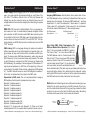
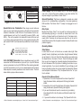
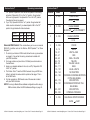
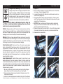
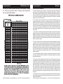
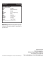
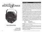
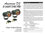
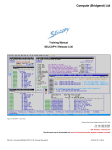
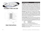
Protron Color™
Introduction
Unpacking: Thank you for purchasing the Protron Color™ by Elation Professional®. Every Protron Color™ has been thoroughly tested
and has been shipped in perfect operating condition. Carefully check
the shipping carton for damage that may have occurred during shipping. If the carton appears to be damaged, carefully inspect your unit
for damage and be sure all accessories necessary to operate the unit
have arrived intact. In the event damage has been found or parts are
missing, please contact our customer support number for further
instructions. Please do not return this unit to your dealer without first
contacting customer support at the number listed below.
Introduction: To optimize the performance of this product, please
read these operating instructions carefully to familiarize yourself with
the basic operations of this unit. The Protron Color™ is a 750 watt
strobe, with a color wheel for colorful strobing. Up to 16 units may be
linked together and controlled by single controller. The units’ intensity,
flash rate, and flash duration can be manually adjusted using the dipswitches. For remote control operation an optional remote control is
available from Elation Professional®.
Customer Support: Elation Professional® provides a customer support line, to provide set up help and to answer any question should
you encounter problems during your set up or initial operation. You
may also visit us on the web at www.elationlighting.com for any comments or suggestions. For service related issue please contact Elation
Professional®. Service Hours are Monday through Friday 9:00 a.m. to
5:00 p.m. Pacific Standard Time.
Voice:
(323) 582-3322
Fax:
(323) 582-3108
E-mail:
[email protected]
Warning! To prevent or reduce the risk of electrical shock or fire, do
User Instructions
Elation Professional®
©
3/04
4295 Charter Street
Los Angeles Ca. 90058
www.elationlighting.com
not expose this unit to rain or moisture.
Caution! There are no user serviceable parts inside this unit. Do not
attempt any repairs yourself, doing so will void your manufactures
warranty.
Please do not discard the shipping carton in the trash. Please recycle
when ever possible.
©Elation
Professional® - www.elationlighting.com - Protron Color™ Instruction Manual Page 2
Protron Color™
•
•
•
•
•
•
•
•
Features
Bright 750 Watt Lamp
Adjustable Flash Rate, Intenstiy Rate, and Flash Duration
Colorful Strobing
Large coverage area
Thermostat Protection
Easy lamp Replacement
Link Up To 16 Units Together
Built-In Adjustable Hanging Yoke
Protron Color™
Warranty Registration
The Protron Color™ carries a two year (730 days) limited warranty.
Please fill out the enclosed warranty card to validate your purchase.
All returned service items whether under warranty or not, must be
freight pre-paid and accompany a return authorization (R.A.) number.
The R.A. number must be clearly written on the outside of the return
package. A brief description of the problem as well as the R.A. number must also be written down on a piece of paper and included in
the shipping container. If the unit is under warranty, you must provide
a copy of your proof of purchase invoice. You may obtain a R.A. number by contacting customer support at (323) 582-3322.
Protron Color™
Cleaning Instructions
Due to fog residue, smoke, and dust cleaning the fixture should be
carried out periodically to optimize light output.
1. Use normal glass cleaner and a soft cloth to wipe down the outside casing every 20 days.
2. Use normal glass cleaner with a soft cloth to wipe down the inside
reflector and lens every 30-60 days.
3. Always be sure to dry all parts completely before plugging the
unit back in.
4. Frequent cleaning the unit will extend lamp life and ensure the fixtures reliability.
Cleaning frequency depends on the environment in which the fixture
operates (I.e. smoke, fog residue, dust, dew). In heavy use we recommend cleaning on a monthly basis. Periodic cleaning will ensure
longevity, and crisp beam output.
©Elation
Professional® - www.elationlighting.com - Protron Color™ Instruction Manual Page 3
Protron Color™
Safety Warnings
Safety Issues: This unit may blow a fuse if the maximum allotted
load of 20 amps (10 amps 220v version) is reached. If the fuse needs
replacement, always replace the fuse with same exact type that was
remove, unless otherwise instructed by an authorized Elation Professional® service technician. Use of a different type fuse from that which
is recommended may cause fire or electric shock and will void the
manufactures warranty.
• To reduce the risk of electrical shock or fire, do not expose this unit
rain or moisture.
• Do not spill water or other liquids into or on to your unit.
• Do not attempt to remove or break off the ground prong from the
electrical cord. This prong is used to reduce the risk of electrical
shock and fire in case of an internal short. Do not attempt to operate this unit if the power cord has been frayed or broken.
• Disconnect from main power before making any type of connection.
• Do not remove the cover under any conditions. There are no user
serviceable parts inside.
• Always be sure to mount this unit in an area that will allow proper
ventilation. Allow about 6” (15cm) between this device and a wall.
• Do not attempt to operate this unit, if it becomes damaged.
• This unit is intended for indoor use only, use of this product outdoors voids all warranties.
• During long periods of non-use, disconnect the unit’s main power.
• Always mount this unit in safe and stable matter.
• Power cords should be routed so they are not likely to be walked
on, pinched by items placed upon or against them.
• Cleaning -The fixture should be cleaned only as recommended by
the manufacturer. See page 3 for cleaning details.
• Heat -The appliance should be situated away from heat sources
such as radiators, heat registers, stoves, or other appliances
(including amplifiers) that produce heat.
• The fixture should be serviced by qualified service personnel when:
A. The power-supply cord or the plug has been damaged.
B. Objects have fallen, or liquid has been spilled into the unit.
C. The unit has been exposed to rain or water.
D. The unit does not appear to operate normally or exhibits a
marked change in performance.
©Elation
Professional® - www.elationlighting.com - Protron Color™ Instruction Manual Page 4
Protron Color™
DMX Set Up
Protron Color™
sound activation.
Power Supply: Before plugging your unit in, be sure the source voltage in your area matches the required voltage for your Elation® Protron Color.™ The Elation® Protron Color™ is 120v only. Because line
voltage may vary from venue to venue, you should be sure your unit
voltages matches the wall outlet voltage before attempting to operate
you fixture.
Assigning DMX Address: Each dipswitch has a preset value. A specific DMX address is set by combining the dipswitches that sum your
desired value. For example: To achieve a DMX address of 7, combine
dipswitches 1, 2, and 3. Since dipswitch 1 has a value of 1, dipswitch
2 has a value of 2, and dipswitch 3 has a value of 4, the combination
of the three create a DMX value of 7. (See example below).
DMX-512: DMX is short for Digital Multiplex. This is a universal protocol used as a form of communication between intelligent fixtures
and controllers. A DMX controller sends DMX data instructions from
the controller to the fixture. DMX data is sent as serial data that travels from fixture to fixture via the DATA “IN” and DATA “OUT” XLR terminals located on all DMX fixtures (most controllers only have a DATA
“OUT” terminal).
DMX Linking: DMX is a language allowing all makes and models of
different manufactures to be linked together and operate from a single controller, as long as all fixtures and the controller are DMX compliant. To ensure proper DMX data transmission, when using several
DMX fixtures try to use the shortest cable path possible. The order
in which fixtures are connected in a DMX line does not influence the
DMX addressing. For example; a fixture assigned a DMX address of 1
may be placed anywhere in a DMX line, at the beginning, at the end,
or anywhere in the middle. When a fixture is assigned a DMX address
of 1, the DMX controller knows to send DATA assigned to address 1
to that unit, no matter where it is located in the DMX chain.
Dipswitches in DMX mode: This unit uses dipswitches to assign a
DMX address. Each dipswitch represents a binary value.
Dipswitch 1 address equals 1
Dipswitch 2 address equals 2
Dipswitch 3 address equals 4
Dipswitch 4 address equals 8
Dipswitch 5 address equals 16
Dipswitch 6 address equals 32
Dipswitch 7 address equals 64
Dipswitch 8 address equals 128
Dipswitch 9 address equals 256
Dipswitch 10 - Some units omit dipswitch 10. When a unit does
include dipswitch #10, it is usually used for special functions such as
©Elation
Professional® - www.elationlighting.com - Protron Color™ Instruction Manual Page 5
DMX Set Up
Set DMX address 1:
Dip-switches # 1 = 1
SOUND
Set DMX address 7:
Dip-switches #
1=1
2=2
3=4
=7
Data Cable (DMX Cable) Requirements (For
DMX and Master/Slave Operation): The Protron
Color™ can be controlled via DMX-512 protocol.
The Protron Color™ is a five channel DMX unit.
The DMX address is set on the side panel of the
Protron Color™ Your unit and your DMX controller
require a standard 3-pin XLR connector for data
input and data output (Figure 1). If you are making
Figure 1
your own cables, be sure to use standard two conductor shielded cable (This cable may be purchased at almost all pro
sound and lighting stores). Your cables should be made with a male
and female XLR connector on either end of the cable. Also remember
that DMX cable must be daisy chained and can not be split.
REMOTE
CONTROL
INPUT
INPUT
OUTPUT
REMOTE
CONTROL
INPUT
SOUND
INPUT
POWER
OUTPUT
SOUND
POWER
Notice: Be sureDMX512
to follow figures two and three when making your own
DMX+,DMX-,COMMON
cables. Do not
use the ground lug on the XLR connector. Do not connect the cable’s shield conductor to the ground lug or allow the shield
conductor to come in contact with the XLR’s outer casing. Grounding
the shield could cause a short circuit and erratic behavior.
COMMON
DMX512 OUT
3-PIN XLR
1
3
2
DMX +
DMX -
1
3
2
1
DMX512 IN
3-PIN XLR
3
2
Figure 2
©Elation
Termination reduces s
avoids signal transmi
and interference. It is a
to connect a DMX term
120 Ohm 1/4 W) betwe
and PIN 3 (DMX +) of
Professional® - www.elationlighting.com - Protron Color™ Instruction Manual Page 6
Protron Color™
DMX Set Up
XLR Female Socket
XLR
Male Socket
REMOTE
INPUT
CONTROL
1 Ground
INPUT
OUTPUT
2 Cold
2 Cold
XLRREMOTE
Pin Configuration
INPUT OUTPUT
SOUND
CONTROL
INPUT
1 Ground
Pin 1 = Ground
Pin 2 = Data Compliment (negative)
3 Hot
3 Hot
Pin 3 = Data True (positive)
Figure 3
Special Note: Line Termination. When longer runs of cable are
POWER
POWER
used, you may need to use a terminator on the last unit to avoid erratic
behavior. A terminator is a 90-120 ohm 1/4 watt resistor which is connected between pins 2 and 3 of a male XLR connector (DATA + and
DATA -). This unit is inserted in the female XLR socket of the last unit
in your daisy chain to terminate the line. Using a cable terminator (ADJ
part number Z-DMX/T) will decrease the possibilities of erratic behavior.
1
3
2
Termination reduces signal errors and
avoids signal transmission problems
and interference. It is always advisable
to connect a DMX terminal, (Resistance
120 Ohm 1/4 W) between PIN 2 (DMX-)
and PIN 3 (DMX +) of the last fixture.
1
DMX512 IN
3-PIN XLR
3
2
Operating Instructions
Power Supply: This unit is available only in 120v. Before plugging
your unit in be sure the source voltage in your area matches the
required voltage for your Elation® Protron Color.™
General Operation: This fixture is designed to operate as a stand
alone unit, or in a Master/Slave configuration. It can also operate via
DMX controller. The Protron Color™ is ready to be plugged in out of
the box.
Duty Cycle:
Because the Protron Color™ can be used for continuous output (ie
while simulating lightning), it can build up intense heat. Due to the
build up of intense heat the unit should not run for 15 minutes continuously. After 15 minutes of continuous use, allow the unit to cool for
about fifteen minutes, this will greatly increase the lamp life and insure
product longevity.
Operating Modes:
Stand Alone:
Figure 4
5-Pin XLR DMX Connectors. Some manufactures use 5-pin XLR
connectors for DATA transmission in place of 3-pin. 5-pin XLR fixtures
may be implemented in a 3-pin XLR DMX line. When inserting standard
5-pin XLR connectors in to a 3-pin line a cable adaptor must be used,
these adaptors are readily available at most electric stores. The chart
below details a proper cable conversion.
3-Pin XLR to 5-Pin XLR Conversion
Conductor
3-Pin XLR Female (Out)
5-Pin XLR Male (In)
Ground/Shield
Pin 1
Pin 1
Data Compliment (- signal)
Pin 2
Pin 2
Data True (+ signal)
Pin 3
Pin 3
©Elation
Protron Color™
Not Used
Pin 4 - Do Not Use
Not Used
Pin 5 - Do Not Use
Professional® - www.elationlighting.com - Protron Color™ Instruction Manual Page 7
In stand alone the unit will function as a normal strobe light. Rate
(speed), Intensity (brightness), and duration (length between flashes)
are set directly on the unit. Note that these settings are made using
the dipswitches on the back of the unit. Once the settings are made
they can only be changed by physically adjusting the dipswitches on
the unit. Be aware of this if you plan on installing your strobe in a permanent application, if your are not satisfied with your settings you will
have to physically remove the unit and adjust the dipswitches. Please
see the dipswitch traits below. “Flip” the dipswitches to the “on” postion to activate.
Dipswitch Traits (Manual Mode):
1. Dipswitches 1-3 control the speed of the strobe. Dipswitch #1
being the slowest strobe, and dipswitch #3 being the fastest
strobe.
2. Dipswitches 4-6 control the brightness of the strobe. Dipswitch #4
being the dimmest, dipswitch #6 being the brightest.
3. If you want the strobe to be set to one color only (no rotation),
leave dipswitch #9 in the off postion, and follow the small chart
on page 9.
4. If you want the strobe to color change, “flip” dipswitch #9 to the
©Elation
Professional® - www.elationlighting.com - Protron Color™ Instruction Manual Page 8
Protron Color™
Operating Instructions
“on” postion. Dipswitch #7 will control the speed of the rotating
gel wheel. If dipswitch #7 is in the “on” postion, the gel wheel
will be on high speed, if the dipswitch #7 is in the “off” postion
the wheel will be on low speed.
5. If you “flip” dipswitch #8 to the “on” postion the gel wheel will
rotate counter-clockwise. If you leave dipswitch #8 in the “off”
postion the gel wheel will rotate clockwise.
COLOR
WHITE RED YELLOW BLUE
DIPSWITCH #7
OFF
ON
OFF
ON
DIPSWITCH #8
OFF
OFF
ON
ON
Universal DMX Control: This mode allows you to use a universal
DMX-512 controller such as the Elation® DMX Operator™ or Show
Designer.™
1. To control your fixture in DMX mode, follow the set-up procedures
on pages 5-7 as well as the set-up procedures included with
your DMX controller.
2. For longer cable runs (more than a 100 feet) use a terminator on
the last fixture.
3. Assign your desired address to the unit, and “flip” dipswitch #10
to the “on” postion.
4. The Protron Color™ uses five DMX channels. Use your DMX controller to activate the various built-in patterns. See page 11 for a
list of DMX traits.
5. For help operating in DMX mode consult the manual included
with your DMX controller.
NOTE: If running in Master/Slave address configuration while using a
DMX controller, follow the DMX address setttings on page 14.
Protron Color™
Channel
Value
1
0 - 255
DMX Traits
Function
FLASH SPEED
SLOW
2
0 - 255
FLASH DIMMER
BLACKOUT
3
0 - 255
FULL INTENSITY
FLASH DURATION
0 -16
4
0 - 255
0 - 15
16 - 31
32 - 47
48 - 63
64 - 79
80 - 95
96 - 111
112 - 127
128 - 144
145 - 159
160 - 175
176 - 191
192 - 207
208 - 255
5
0 - 255
COLOR
WHITE
WHITE + RED
RED
RED + YELLOW
YELLOW
YELLOW + BLUE
BLUE
BLUE + WHITE
NO FUNCTION
COUNTER-CLOCKWISE ROTATION
OF THE GEL WHEEL
NO FUNCTION
CLOCKWISE ROTATION OF THE
GEL WHEEL
NO FUNCTION
INTERNAL PROGRAM
GEL WHEEL ROTATION SPEED
SLOW
©Elation
Professional® - www.elationlighting.com - Protron Color™ Instruction Manual Page 10
FAST
©Elation
FAST
Professional® - www.elationlighting.com - Protron Color™ Instruction Manual Page 11
Protron Color™
Lamp Replacement
Halogen Lamp Warning! This fixture is fitted with
halogen lamps which are highly susceptible to damage if improperly handled. Never touch the lamps
with your bare fingers as the oil from your hands will
shorten lamp life. Also, never move the fixture until
the lamps have had ample time to cool. Remember,
lamps are not covered under warranty conditions.
Warning! Allow the lamp to discharge all current. Allow the
unit 24hrs. to discharge before changeing the lamp. Stored
current can cause a very severe shock.
Caution: Always replace with the exact same type lamp and fuse,
unless otherwise specified by an authorized Elation Professional®
technician. Replace with anything other than the specified part can
damage your unit and will void your manufactures warranty.
Protron Color™
Lamp Replacement
(diagram 1).
4. Gently rotate the reflector by hand so that the back of the reflector is now in the front (diagram 2 & 3).
5. Located at the back of the reflector is a white ceramic wire connection block (diagram 4).
3. The ceramic block has six wires connected to it, three on each
side. The three wires on the left side are the lamp wires, they are
secured by a flat head screw.
4. NOTICE: When you disconnect the lamp wires to replace the
lamp, you will have to remember which wire went where. They
must be reconnected the same way.
4. Replace the lamp with an exact match. Connect the three wires to
the ceramic block as they were when you disconnected them.
5. Reassemble in reverse order.
Warning: If after you have replaced the lamp or fuse and you contin-
Diagram 1
Diagram 2
Diagram 3
Diagram 4
ue to blow either one, STOP using the unit. Contact customer support
for further instructions, you may have to return the unit for servicing.
Continuing to use the unit may cause serious damage.
Fuse Replacement: Disconnect the unit’s main power supply.
Insert a standard flat head screw driver in to the fuse holder housing (located on the rear of the unit). Turn the screwdriver in a counter-clockwise direction to remove the fuse holder. Remove the old
fuse and discard it, replace the fuse with the same type. Insert the
fuse holder back into it’s housing and turn in a clockwise direction to
secure the holder in place.
Lamp Replacement: Caution! Never open the unit when in use.
Always disconnect the main power and allow the fixture ample time
to cool before attempting to replace the lamp. Lamp replacement has
been made simple by incorporating a remove tray that is retained by a
single thumb screws. Again, please remember to always replace with
the exact same type lamp.
1. Be sure to follow the proper procedures when handling halogen
lamps. Never touch the new lamp with your bare fingers.
2. Unscrew the two thumb screws located on the glass cover in the
top corners of the unit.
3. Loosen the small phillips screw located to the right of the reflector
©Elation
Professional® - www.elationlighting.com - Protron Color™ Instruction Manual Page 12
©Elation
Professional® - www.elationlighting.com - Protron Color™ Instruction Manual Page 13
Protron Color™
DMX Address Chart
This chart list the DMX dipswitch setting for DMX address 1 through
511. Follow the instructions below to configure fixture dipswitches
with your desired DMX address.
Protron Color™
Warranty
2-YEAR LIMITED WARRANTY
A. Elation Professional® hereby warrants, to the original purchaser, Elation Professional®
products to be free of manufacturing defects in material and workmanship for a period of
two years (730 days) from the date of purchase. This warranty shall be valid only if the product is purchased within the United States of America, including possessions and territories.
It is the owner’s responsibility to establish the date and place of purchase by acceptable
evidence, at the time service is sought.
B. For warranty service, send the product only to the Elation Professional® factory. All
shipping charges must be pre-paid. If the requested repairs or service (including parts
replacement) are within the terms of this warranty, Elation Professional® will pay return shipping charges only to a designated point within the United States. If the entire instrument
is sent, it must be shipped in its original package. No accessories should be shipped with
the product. If any accessories are shipped with the product, Elation Professional® shall
have no liability whatsoever for loss of or damage to any such accessories, nor for the safe
return thereof.
C. This warranty is void if the serial number has been altered or removed; if the product is
modified in any manner which Elation Professional® concludes, after inspection, affects the
reliability of the product; if the product has been repaired or serviced by anyone other than
the Elation Professional® factory unless prior written authorization was issued to purchaser
by Elation Professional®; if the product is damaged because not properly maintained as set
forth in the instruction manual.
D. This is not a service contract, and this warranty does not include maintenance, cleaning
or periodic check-up. During the period specified above, Elation Professional® will replace
defective parts at its expense, and will absorb all expenses for warranty service and repair
labor by reason of defects in material or workmanship. The sole responsibility of Elation
Professional® under this warranty shall be limited to the repair of the product, or replacement thereof, including parts, at the sole discretion of Elation Professional®. All products
covered by this warranty were manufactured after January 1, 1990, and bear identifying
marks to that effect.
E. Elation Professional® reserves the right to make changes in design and/or improvements upon its products without any obligation to include these changes in any products
theretofore manufactured.
F. No warranty, whether expressed or implied, is given or made with respect to any accessory supplied with products described above. Except to the extent prohibited by applicable
law, all implied warranties made by Elation Professional® in connection with this product,
including warranties of merchantability or fitness, are limited in duration to the warranty
period set forth above. And no warranties, whether expressed or implied, including warranties of merchantability or fitness, shall apply to this product after said period has expired.
The consumer’s and or Dealer’s sole remedy shall be such repair or replacement as is
expressly provided above; and under no circumstances shall Elation Professional® be liable
for any loss or damage, direct or consequential, arising out of the use of, or inability to use,
this product.
G. This warranty is the only written warranty applicable to Elation Professional® Products
and supersedes all prior warranties and written descriptions of warranty terms and conditions heretofore published.
©Elation
Professional® - www.elationlighting.com - Protron Color™ Instruction Manual Page 14
©Elation
Professional® - www.elationlighting.com - Protron Color™ Instruction Manual Page 15
Protron Color™
Specifications
Model: Protron Color™
Voltage*:
Lamp:
Fuse:
Dimensions:
Weight:
Colors:
Duty Cycle:
Ventilation:
Warranty:
120v~60Hz
ZB-300 750 Strobe lamp
20A 250v
10” (L) x 22” (W) x 9.6” (H)
24 Lbs.
3 Plus White
15 minutes on/off
Fan Cooled
2 Year (730 Days)
*Voltage is preset at the factory and can not be changed by the user.
Please Note: Specifications and improvements in the design
of this unit and this manual are subject to change without any
prior written notice.
©Elation
©Elation
Professional® - www.elationlighting.com - Protron Color™ Instruction Manual Page 16
Professional®
Elation World Headquarters:
4295 Charter Street Los Angeles, CA 90058 USA
Tel: 323-582-3322 / Fax: 323-582-3108
Web: www.elationlighting.com / E-mail: [email protected]